

Page 1
HyperMag-1200-LW indoor bicycle trainer
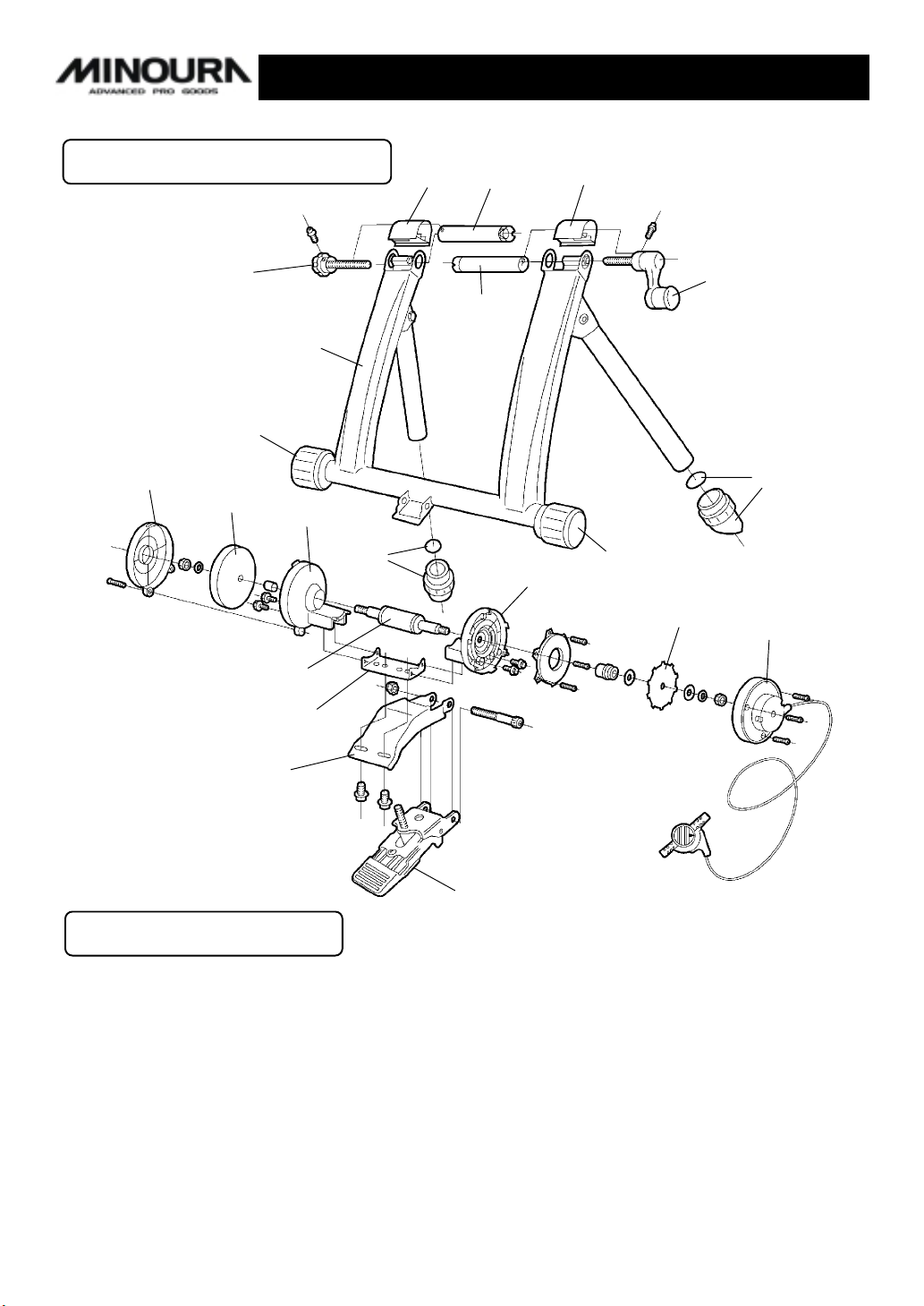
RESOLUTION DIAGRAM
F-8
HF-3
M8-3
HM-11
HM-12
HM-2
HM-8
M8-4
F-4
F-1
F-2
HM-3
F-4
M8-3
HM-7
F-7
M8-4
HM-5
HM-9
HM-13
LM-13
WARRANTY PARTS
F-1 : Coupling (Right) HM-2 : Flywheel Side Inner Case
F-2 : Coupling (Left) HM-3 : Mag Side Inner Case
F-4 : Coupling Cover HM-5 : Remote Outer Cover
F-7 : Hub Handle HM-7 : Alloy Rotor
F-8 : Left Knob Bolt HM-8 : Axle w/ Bearings
HF-3 : HyperMag Main Frame HM-9 : Connection Plate
M8-3 : Rubber Frame Cap HM-11: Flywheel Cover (yellow)
M8-4 : Rubber Foot Cap (35mm) HM-12: Flywheel (1,200g)
HM-13: Base Plate
LM-13: Foot Pedal
- 1 -
Page 2
IMPORTANT NOTES
• Read all instructions including the back page of the POP card board carefully before• Read all instructions including the back page of the POP card board carefully before
• Read all instructions including the back page of the POP card board carefully before
• Read all instructions including the back page of the POP card board carefully before• Read all instructions including the back page of the POP card board carefully before
use.use.
use.
use.use.
• Some assembly required.• Some assembly required.
• Some assembly required.
• Some assembly required.• Some assembly required.
• Keep the manual handy at all times.• Keep the manual handy at all times.
• Keep the manual handy at all times.
• Keep the manual handy at all times.• Keep the manual handy at all times.
• Do NOT use trainer for any other purpose than instructed.• Do NOT use trainer for any other purpose than instructed.
• Do NOT use trainer for any other purpose than instructed.
• Do NOT use trainer for any other purpose than instructed.• Do NOT use trainer for any other purpose than instructed.
• The trainer is manufactured to precise standards. You may not disassemble or• The trainer is manufactured to precise standards. You may not disassemble or
• The trainer is manufactured to precise standards. You may not disassemble or
• The trainer is manufactured to precise standards. You may not disassemble or• The trainer is manufactured to precise standards. You may not disassemble or
rebuild it.rebuild it.
rebuild it.
rebuild it.rebuild it.
• "Magturbo" is the trademarks of Minoura Co.,Ltd. and may not be copied.• "Magturbo" is the trademarks of Minoura Co.,Ltd. and may not be copied.
• "Magturbo" is the trademarks of Minoura Co.,Ltd. and may not be copied.
• "Magturbo" is the trademarks of Minoura Co.,Ltd. and may not be copied.• "Magturbo" is the trademarks of Minoura Co.,Ltd. and may not be copied.
WARNINGS
Use two-wheeled bicycles only. Tandems may be used if balanced correctly.Use two-wheeled bicycles only. Tandems may be used if balanced correctly.
Use two-wheeled bicycles only. Tandems may be used if balanced correctly.
Use two-wheeled bicycles only. Tandems may be used if balanced correctly.Use two-wheeled bicycles only. Tandems may be used if balanced correctly.
!
Replace your quick release skewer to the supplied one and install the suppliedReplace your quick release skewer to the supplied one and install the supplied
Replace your quick release skewer to the supplied one and install the supplied
Replace your quick release skewer to the supplied one and install the suppliedReplace your quick release skewer to the supplied one and install the supplied
!
coupling protector cap onto the right side coupling when you use the trainer. Other-coupling protector cap onto the right side coupling when you use the trainer. Other-
coupling protector cap onto the right side coupling when you use the trainer. Other-
coupling protector cap onto the right side coupling when you use the trainer. Other-coupling protector cap onto the right side coupling when you use the trainer. Otherwise the stability will not be guaranteed.wise the stability will not be guaranteed.
wise the stability will not be guaranteed.
wise the stability will not be guaranteed.wise the stability will not be guaranteed.
Remove the coupling protector cap when you use your own quick release skewer.Remove the coupling protector cap when you use your own quick release skewer.
Remove the coupling protector cap when you use your own quick release skewer.
Remove the coupling protector cap when you use your own quick release skewer.Remove the coupling protector cap when you use your own quick release skewer.
!
Remove all oils and moisture from the drive roller and the tire before use.Remove all oils and moisture from the drive roller and the tire before use.
Remove all oils and moisture from the drive roller and the tire before use.
Remove all oils and moisture from the drive roller and the tire before use.Remove all oils and moisture from the drive roller and the tire before use.
!
Keep both hands on handlebars at all times and maintain a normal riding position.Keep both hands on handlebars at all times and maintain a normal riding position.
Keep both hands on handlebars at all times and maintain a normal riding position.
Keep both hands on handlebars at all times and maintain a normal riding position.Keep both hands on handlebars at all times and maintain a normal riding position.
!
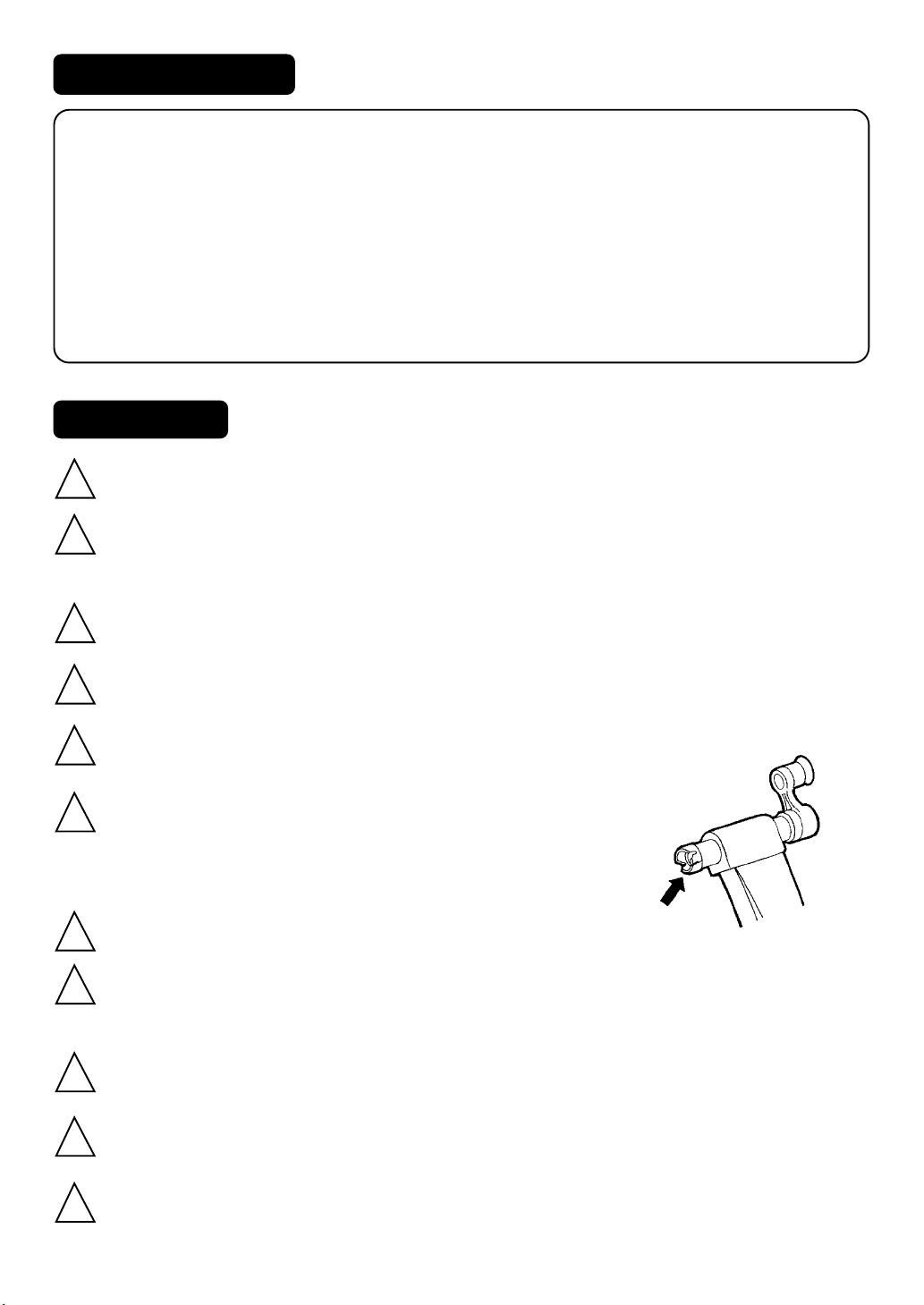
Check the couplings supporting the rear hub for damageCheck the couplings supporting the rear hub for damage
Check the couplings supporting the rear hub for damage
Check the couplings supporting the rear hub for damageCheck the couplings supporting the rear hub for damage
!
and cracks (see Fig. A). Accidents may occur from crackedand cracks (see Fig. A). Accidents may occur from cracked
and cracks (see Fig. A). Accidents may occur from cracked
and cracks (see Fig. A). Accidents may occur from crackedand cracks (see Fig. A). Accidents may occur from cracked
or damaged couplings.or damaged couplings.
or damaged couplings.
or damaged couplings.or damaged couplings.
When using the trainer, place it on a flat surface for safe training.When using the trainer, place it on a flat surface for safe training.
When using the trainer, place it on a flat surface for safe training.
When using the trainer, place it on a flat surface for safe training.When using the trainer, place it on a flat surface for safe training.
!
Do not over tighten the hub-clamp handles. Over-tightening may cause damage toDo not over tighten the hub-clamp handles. Over-tightening may cause damage to
Do not over tighten the hub-clamp handles. Over-tightening may cause damage to
Do not over tighten the hub-clamp handles. Over-tightening may cause damage toDo not over tighten the hub-clamp handles. Over-tightening may cause damage to
!
the trainer or bicycle frame. The clamp handles should be a snug and secure fit. Dothe trainer or bicycle frame. The clamp handles should be a snug and secure fit. Do
the trainer or bicycle frame. The clamp handles should be a snug and secure fit. Do
the trainer or bicycle frame. The clamp handles should be a snug and secure fit. Dothe trainer or bicycle frame. The clamp handles should be a snug and secure fit. Do
not force!not force!
not force!
not force!not force!
Before use, make sure all bolts and nuts are securely fastened.Before use, make sure all bolts and nuts are securely fastened.
Before use, make sure all bolts and nuts are securely fastened.
Before use, make sure all bolts and nuts are securely fastened.Before use, make sure all bolts and nuts are securely fastened.
!
Keep away from small children, and keep hands and feet away from spinning rollersKeep away from small children, and keep hands and feet away from spinning rollers
Keep away from small children, and keep hands and feet away from spinning rollers
Keep away from small children, and keep hands and feet away from spinning rollersKeep away from small children, and keep hands and feet away from spinning rollers
!
and wheels at all times.and wheels at all times.
and wheels at all times.
and wheels at all times.and wheels at all times.
(Fig. A)
Open the legs fully to get maximum stability.Open the legs fully to get maximum stability.
Open the legs fully to get maximum stability.
Open the legs fully to get maximum stability.Open the legs fully to get maximum stability.
!
- 2 -
Page 3

How To Setup Your HyperMag1200 Trainer
Open the frame support legs and fit the rubber feet at the correct angle so the base is in full contact with the
1
floor. Do NOT remove the round metal plates from inside the rubber feet when fitting.
NOTE: If the both legs don’t touch the floor at same time and if one side of the leg is still being lifted
up slightly, pull up the leg upward strongly then place the trainer on the floor again.
Open both couplings by turning the right side hub handle (see Fig. B)
2
anti-clockwise.
Do not over-loosen the couplings, otherwise the knob or the hub handle
may become unthreaded inside the frame.
Insert the left side of the skewer (quick release lever side) into the left
3
side coupling, and adjust the rotation of the coupling so the skewer
lever sits securely in the large cut-out (see Fig. C). This will prevent
damage to the skewer during use.
Hold the bike firmly by hand and turn the hub handle clockwise until
4
the coupling comes into contact with the right side skewer nut.
Apply the Mag unit to the tire by lifting up it temporally to know the
5
wheel position.
If the tire touches either left or right side platic housing of the Mag unit
(see Fig. D), you must adjust the Mag unit position by loosening two
bolts beneath the Mag unit. Do not forget to tighten the bolts firmly
after adjusting.
Turn the micro adjust knob clockwise to bring the drive roller into con-
6
tact with the rear tire. If the tire is compressed about 3mm by the roller,
stop turning the knob.
WARNING: Too much or too little contact between the tire and the roller can cause prema-
!
ture tire wear and possibly damage the drive roller.
(Fig. B)
(Fig. C)
(Fig. D)
Using The Mag Unit
The Magturbo unit has 7 different levels of load force, replicating actual riding resistance.
The load settings range from high (H) to low (L) and can be adjusted via the white lever on the Magturbo unit or the
lever on the thumb shifter device. The rider may also adjust the load force by shifting up or down among his gears,
depending on the level desired.
We recommend that you start with a medium to low load force and gradually work up, increasing force as muscled
warm up.
- 3 -
Page 4
Increasing Load ForceIncreasing Load Force
Increasing Load Force
Increasing Load ForceIncreasing Load Force
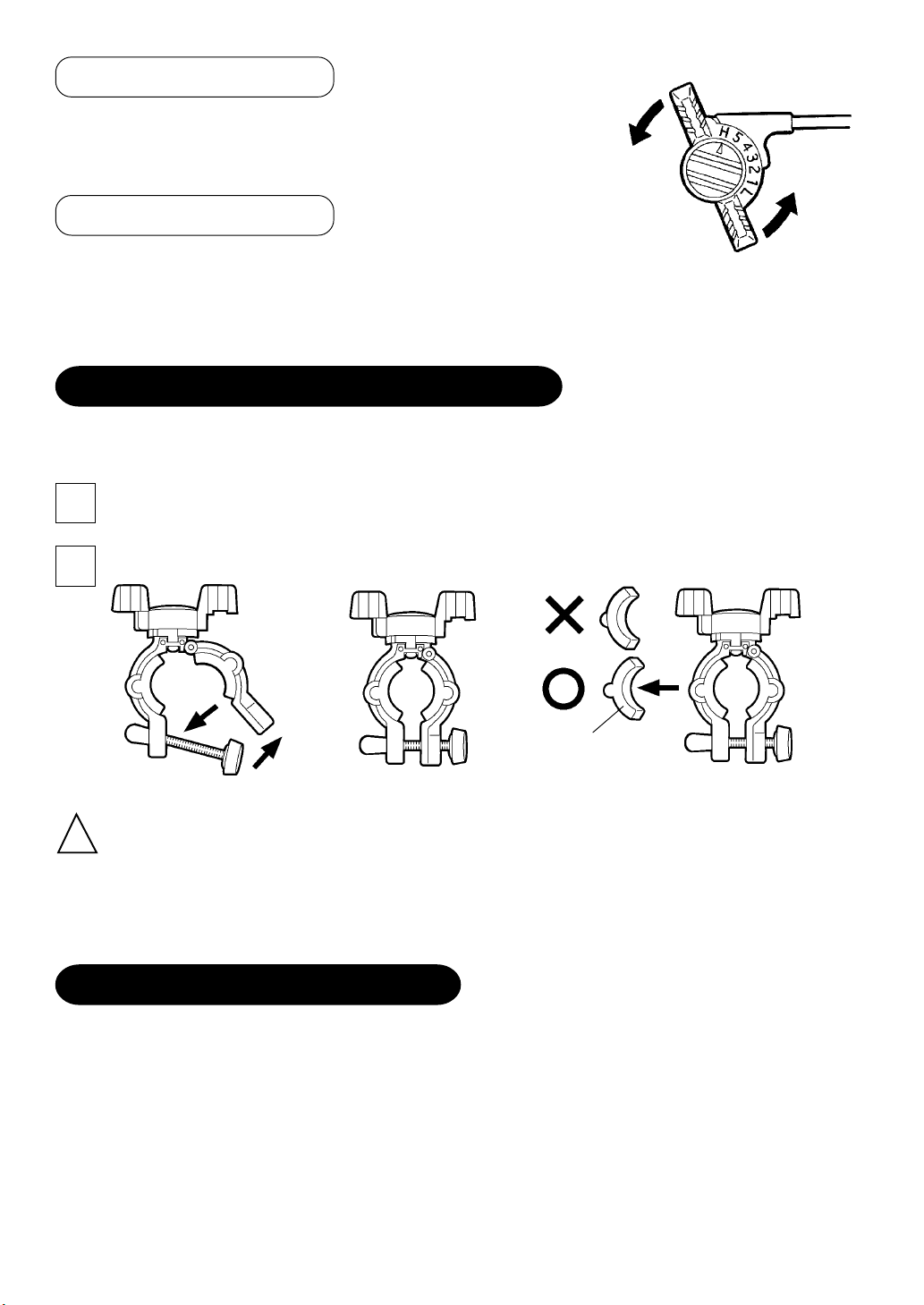
To increase the load force, turn the lever on your thumb shifter device
toward the “H” symbol. (see Fig. E)
Decreasing Load ForceDecreasing Load Force
Decreasing Load Force
Decreasing Load ForceDecreasing Load Force
To decrease the load force, turn the lever on your thumb shifter device toward the
“L” symbol.
Be sure the lowest selection is not zero load, there still be a small level of force.
(Fig. E)
HOW TO INSTALL THE REMOTE LEVER
You can install the remote lever on anywhere the diameter is between 22.2mm (7/8”) and 31.8mm (1-1/4”) like as
on the handlebar.
Fully loosen the knob bolt on the plastic holder until it stops then push down the bolt to open the holder.
1
(see Fig. F)
Place the holder onto the handlebar, shut the holder, and pull up the bolt then tighten it. (see Fig. G)
2
Shim
(Fig. F)
(Fig. G)
(Fig. H)
Depends on the diameter of your handlebar, you must adjust the shim as follows;
!
• 22.2mm (7/8”) - 25.4mm (1”):Install both shims.
• 28.6mm (1-1/8”): Install either right or left side shim.
• 31.8mm (1-1/4”): Remove both shims.
When you install the shim on the plastic holder, make sure the direction of the shim as shown in Fig. H.
USING THE SMALL WHEEL ADAPTER
(Required Tools: M5 hex wrench, 10mm open spanner)
If you wish to use any smaller wheel sized between 24 x 1.0” and 26 x 1.75” on the trainer, install the supplied
adapter under the Mag unit. (see Fig. J)
- 4 -
Page 5

Remove two bolts which hold the Mag unit on the fitting bracket by an
1
M5 hex wrench. Then the Mag unit will be removed.
Install the supplied “Z” shaped adapter on the fitting
2
bracket with the removed bolts.
Make sure the direction of the adapter is exactly same as
shown in Fig. I.
Adapter
Install the Mag unit onto the adapter with the
3
supplied bolts.
Be sure you should use a 10mm open spanner
to tighten these bolts, not by a hex wrench.
10mm Spanner
Trouble Shooting Your Remote Shifter Unit
If you cannot shift to either the lowest (L) or the highest (H) position, it is
possible that the inner wire of the remote shifter cable is too long and the wire
tension is loose. If so, please adjust the tension with the following steps;
Set the remote shifter lever at “H” position. Remove the remote shifter
1
device from the handlebar and straighten the cable.
Remove the plastic cap located on the bottom of the cable. (see Fig. J)
2
Hold the adjusting screw with your right hand and push it towards the
3
direction of the outer cable, then adjust the nut with your left hand to
make the wire tension properly.
Fitting Bracket
(Fig. I)
Nut Plastic Cap
Cable
Wire Tension
Adjusting Screw
(Fig. J)
FOR MORE INFORMATION
MINOURA JAPAN HEAD OFFICEMINOURA JAPAN HEAD OFFICE
MINOURA JAPAN HEAD OFFICE
MINOURA JAPAN HEAD OFFICEMINOURA JAPAN HEAD OFFICE
1197-1 Godo, Anpachi, Gifu 503-2305 JAPAN
Phone +81- (0)584-27-3131 / Fax +81- (0)584-27-7505
E-mail: minoura@minoura.jp
http:// www.minoura.jp
UK DISTRIBUTOR : ZYRO PLCUK DISTRIBUTOR : ZYRO PLC
UK DISTRIBUTOR : ZYRO PLC
UK DISTRIBUTOR : ZYRO PLCUK DISTRIBUTOR : ZYRO PLC
Becklands Close, Bar Lane, Roecliffe, York Y05 9LS, U.K.
Phone 01423-325325 / Fax 01423-323111
Email: zyro@zyro.co.uk
http://www.zyro.eu.com
- 5 -
Made & Quality Controlled in Japan
Copyright © 2003 Minoura Japan, All Rights Reserved.
 Loading...