

Page 1
Indoor Bicycle Trainer “HyperMag” Instruction Manual
Type-D : Dial version
Type-R : Remote version
(Figure: Type-D)
Thank you very much for purchasing the Minoura HyperMag trainer.
HyperMag has been developed as the most silent indoor bicycle trainer in the world with adopting Minoura’s
special technical knowledge for over 12 years such as thicker plastic material, alloy die-casting outer case
and high-level machined unique full-circle magnet.
Also Minoura’s patented magnetic resistance system provides more adjustable load settings and extremely
silent circumstances rather than the fluid resistance unit.
HyperMag will fit any wheel between 26” and 27” include 700c.
-1-
Page 2
WARNING
Use two-wheeled bicycles only. Tandems may be used if balanced correctly.
!
Remove all oils and moisture from the drive roller before use. Be sure the tire slippage just after
!
starting is not abnormal.
Keep both hands on handlebars at all times and maintain a normal riding position.
!
After you ride bicycle on the HyperMag trainer, remove all dirt and particles from the rear tire, so
!
that you'll have effective braking on your future rides.
Check the couplings supporting the rear hub for damage and cracks.
!
Accidents may occur from cracked or damaged couplings.
When using the HyperMag trainer, place it on a flat surface for safe training.
!
Adjust the rear wheel position properly to avoid any trouble such as tire burst that caused by the
!
tire touches the plastic case of the resistance unit.
Do not over-tighten the hub-clamp handles. Over-tightening may cause damage to the trainer or
!
bicycle frame. The clamp handles should be a snug and secure fit. Do not force!
Keep away from small children, hands and feet away from spinning rollers and wheels at all times.
!
Before use, make sure all bolts and nuts are securely fastened.
!
“ICE” system cannot be used on the HyperMag resistance unit.
!
If you will use HyperMag with an MTB, you should change your rear tire to a slick one from a knobby
!
one in order to prevent any problems caused by noise and vibration.
Also be sure there may be a problem that your tire will worn out easily if the roller pressure to the tire
is too weak or too strong. Keep correct pressure with adjusting the knob bolt.
-2-
Page 3

ASSEMBLING HYPER-MAG TRAINER
Coupling
Flywheel
Drive Roller
M6 Bolt
Flat Washer
Knob Bolt
Frame
Spring
Resistance
Unit
M6 Nut
Joint Plate
Load Level
Adjusting Dial
Hub Clamping Handle
U-Leg
Rubber Foot Cap
(Fig. A)
Open the frame and the U-leg, and place on level floor.
1
If the rubber foot caps were twisted, adjust that each flat surfaces fully touch the floor.
Install the joint plate with the supplied M6 bolt and M6 nut. At this time, be sure the welded nut on
2
the joint plate faces to the resistance unit side.
The joint plate must be free for rotating so you do NOT tighten the bolt firmly.
Insert the flat washer and the spring into the knob bolt, then tighten to the joint plate. Make sure
3
the direction of the spring that the smaller diameter must face the plastic knob side.
The joint plate is designed to be foldable.
4
Grab the plate and rotate upward (see Fig.B).
When the plate becomes almost vertical, push down the plate and
insert its hook into the square hole on the frame bracket.
Lastly, pull the plate backward.
Now your next step is ready.
If you purchased the Type-R (remote control version), straighten
5
the remote shifter cable and put it through under the U-leg. Be
sure do not bent the cable, especially at the bottom of it.
-3-
(Fig. B)
Page 4

INSTALLING YOUR BIKE ON HYPER-MAG
Your bike will be supported onto the HyperMag by
clamping the rear axle with both side couplings.
The resistance unit is located behind the bike.
Loosen the knob bolt and lay down the resistance
1
unit in order to make the space for the rear wheel
enough.
Loosen the hub clamping handle to make the
clearance between the couplings wider.
Place your bike in front of the HyperMag and pull
back the bike between the frame pillars.
Lift up the rear part of the bike and attach the left
2
side hub (Q/R side) into the left coupling (see Fig. D).
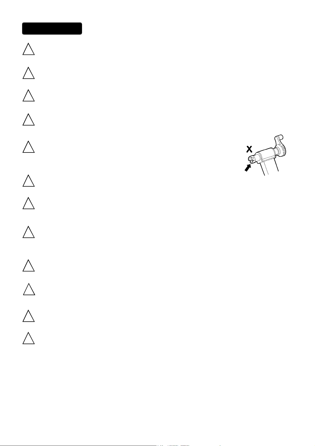
If the lever part of the skewer touches the edge of the
!
coupling, it may be damaged and your weight will not
be able to be supported safely. To avoid this problem,
adjust the angle of the ring on the coupling to be that
the lever will come to the horrow of the ring.
Lift up the bike with using the left hub as the fulcrum and make the rear axle horizontal.
3
Tighten the hub clamping handle and catch the right side (rear cog side) hub with the coupling.
(Fig. C)
(Fig. D)
Harder clamping can supports the bike firmly, but over-tighten may cause a damage on your bike or
!
HyperMag. Stop tightening when the frame pillars start to move outward.
Also you must confirm the stability of the bike everytime you use the HyperMag with shaking the bike
slightly.
If you are the Type-R user, install the remote control device onto the handlebar.
4
Lastly, tighten the knob bolt to press the drive roller to the tire.
5
Be sure that you should stop thightening when the roller touches the
tire, then tighten a half or 1 rotation more (see Fig. G).
If the roller pressure to the tire is too weak or too strong, your tire may
!
worn down incredibly easily. To avoid such problem, keep the pres-
sure properly.
-4-
(Fig. G)
Page 5

ADJUSTING THE LOAD LEVEL
You can choose from 7 different load levels with shifting the adjusting dial (Type-D)
or the remote shifter lever (Type-R).
<INCREASING LOAD LEVEL>
If your model is Type-D, turn the load adjusting dial to the direction
of “H” symbol (see Fig. F).
If your model is Type-R, twist the remote shifter lever to the direc-
tion of “H” symbol (see Fig. H).
Be sure there will be remained minimum load resistance even
!
you shift the lowest position (L). This is caused by the pressure
of the drive roller to the tire.
<DECREASING LOAD LEVEL>
If your model is Type-D, turn the load adjusting dial to the direction
of “L” symbol (see Fig. G).
If your model is Type-R, twist the remote shifter lever to the direc-
tion of “L” symbol (see Fig. H).
Increasing
(Fig. F)
Decreasing
(Fig. G)
Decreasing
<PROBLEMS ON TYPE-R (remote version)>
If you experience a trouble that the load level will increase auto-
matically, the remote shifter lever may loosen. On the system of
HyperMag, the inside spinning alloy plate pulls the magnet plate
and this phenomenon happens.
To solve this problem, adjust the center small knob nut on the re-
mote shifter device.
If you cannot shift to either the lowest (L) or the highest (H) position,
it is possible that the inner wire of the remote shifter cable is being
longer and the wire tension is loose. If so, please adjust the tension
with the following steps;
1.
Set the remote shifter lever at “H” position. Remove the remote shifter device from the handlebar and
straighten the cable.
2.
Remove the plastic cap located on the bottom of the cable (see Fig. I ).
Nut Plastic Cap
Wire Tension
Adjusting Screw
Increasing
(Fig. H)
Cable
(Fig. I)
3.
Hold the adjusting screw with your right hand and push it to the direction of the outer cable, then adjust
the nut with your left hand to make the wire tension properly.
-5-
Page 6

ABOUT OPTIONAL ITEMS
•REMOTE SHIFTER KIT
If you are the Type-D (dial version) owner, you can change the outer case of the resistance unit to be Type-
R (remote version). Order “Remote Shifter Kit” at your local Minoura dealer.
•HYPER-BRAIN CYCLE COMPUTER
“HyperBrain” cycle computer is available as a convenient option for both Type-D and Type-R.
This computer features 7 functions and measures the speed data directly from the drive roller, not from
the wheel like as normal cycle computer. So you can expect always exact speed data even you use
different size wheel on the HyperMag.
If you use the Type-R, the HyperBrain can be installed onto the remote shifter device directly.
The speed sensor of the HyperBrain is installed on the hole of the flywheel cover. This hole is covered with
a silver sticker. If you peel off the sticker and you don’t install the HyperBrain, a noise will happen so you
should not remove it if you don’t get the HyperBrain yet.
RESOLUTION DIAGRAM
FOR MORE INFORMATION
MINOURA NORTH AMERICA
37653 B Argyle Rd.
Fremont, CA 94536-4918 U.S.A.
Phone 510-739-1395 / Fax 510-790-1108
E-mail : MinouraUSA@ATTglobal.net
MINOURA JAPAN
1197-1 Godo, Anpachi, Gifu 503-2305 JAPAN
Phone (+81) 584-27-3131 / Fax (+81) 584-27-4258
Email : minoura@minoura.co.jp
http://www.minoura.co.jp
-6-
 Loading...