

Page 1
!
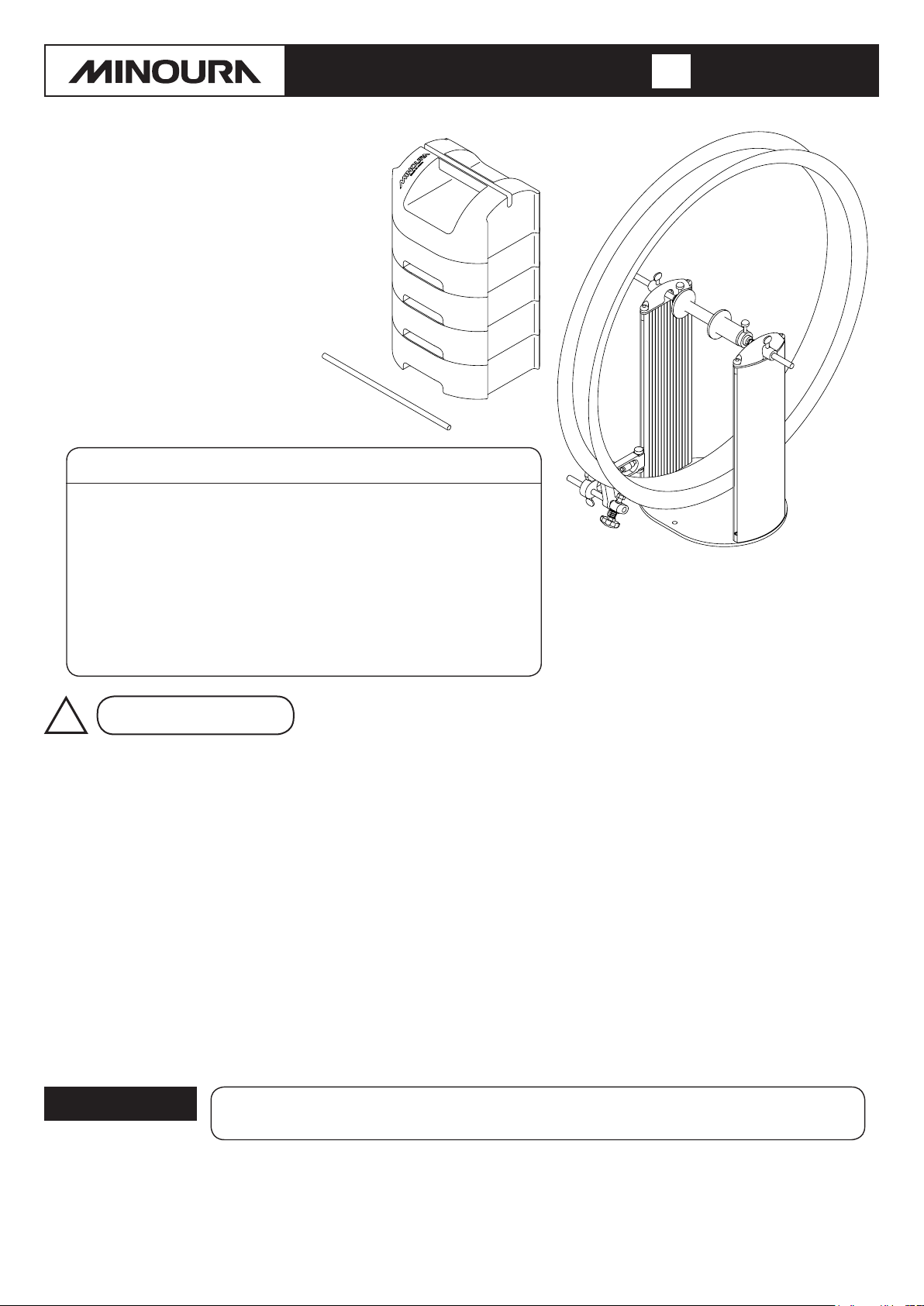
Bicycle Wheel Truing Stand
The FT-50W is the wider version of
the FT-50. This version offers tool
storage and a handy carrying handle
for easy transportation and storage.
Read this instruction manual
carefully before use.
Keep this manual in hand
while you use this product.
FT-50 W
instruction manual
(ver.1.0 2018/10)
Warranty Period :
Minoura offers 1-year limited warranty service to the original owner
of this product from the date of the purchase.
Any problems caused by the manufacturer's defect will be solved by
free repair or replacing the whole product or necessary parts.
However, any problems caused by user's misuse, unapproved
modification and disassembling, damage during use or shipping, or
expected natural wear will not be covered by this program.
Please read the enclosed warranty card for more details. And
Minoura strongly suggest to check out our web site regularly for the
latest update.
1 year
Important Notes
• FT-50W is a special tool for precisely maintaining the
bicycle wheel. Do not use this product for any other
purpose than instructed.
• Remove the quick release (Q/R) skewer from your
wheel before use.
• We recommend removing the tire from the wheel before
use.
• The max wheel hub width is 210mm that covers most
wide rims for fat bikes. Remove the spring from the right
side coupling axle when you mount a wide hub.
• Clamps on a standard 9mm Q/R using the side
couplings.
• 12mm or 15mm thru axle type hubs are also compatible.
Insert the supplied adapters in the hub hole for
mounting.
• Please note that a small amount of rim surface scratches
from the tips is normal. Especially on carbon or softer
metal wheels.
• Do not spin the wheel too fast. Rotate slowly.
• The verticality of the pillar is the most important matter
• Your wheels are critical to your riding safety. You assume
• Minoura is not responsible for any issues encountered
[In-Use Image with wide rim]
on FT-50W. Do not apply any shock or damage to the
pillars even while storing.
all responsibility for working on your wheels. Minoura
is not responsible for any issues that might arise from
truing your wheels. If you have doubts, please take your
wheels to a professional mechanic for service.
with your wheels after using the product. Make sure you
know what you're doing. If you have any doubts in your
abilities, consult a professional. Minoura is supplying
tool to do a job, but learning how to use this tool is your
responsibility.
Contact
If you have question or problem on this product, please contact the shop where you originally purchase this product or
the distributor in your country first. The distributor information can be found on our web site. Only when you cannot
obtain enough service from them, you can contact Minoura directly.
MINOURA JAPAN MINOURA NORTH AMERICAN TECH CENTER
(for ALL customers, including Canada) (for U.S. residents ONLY)
1197-1 Godo, Anpachi, Gifu 503-2305 Japan Mon - Fri, 9 am - 5 pm (PCT)
Fax +81-584-27-7505 Phone 1-510-538-8599 / Fax 1-510-538-5899
minoura@minoura.jp / www.minoura.jp support@minourausa.com
Made in Japan
Page 2
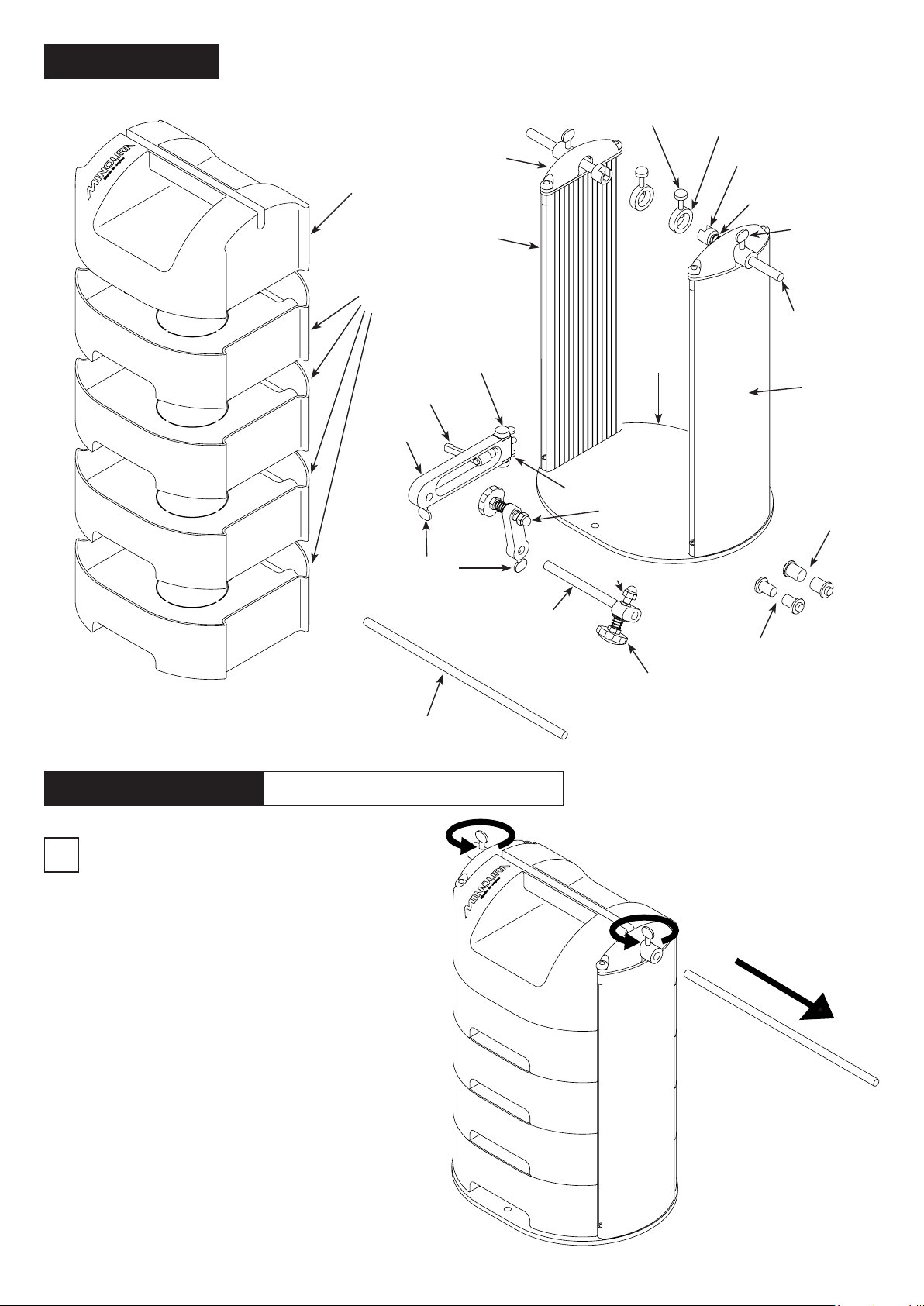
Schematics
(In this manual, we are explaining with the gauge mounted on the left side.
Of course, it can be set on the right side too.)
Tool Box
Top Cover
Tool Box +
Cushion Pad
(4 sets)
Lever Bolt
Gauge Base
Top Cover
Left Pillar
Metal Knob Bolt
Metal Knob Bolt
Base
Plate
Mounting
Bracket
Horizontal
Shaking
Gauge
Coupling
Guide Ring
Coupling
Spring
(Right side only)
Buttery Bolt
Coupling
Shaft
Right Pillar
15mm Thru
Axle Adapter
(Large)
How To Assemble
Gently place the FT-50W on your work
1
bench.
Required Tool :
Loosen the butterfly bolts on top of the
pillars, then the rod can be removed.
(Fig. A)
If removal is difficult, we suggest using a
pen to help push the rod through.
Buttery Bolt
Tool Box Fixing Rod
5mm Hex Wrench
Gauge Shaft
Vertical Shaking Gauge
Plastic Knob Bolt
12mm Thru
Axle Adapter
(Small)
- 2 -
(Fig. A)
Page 3
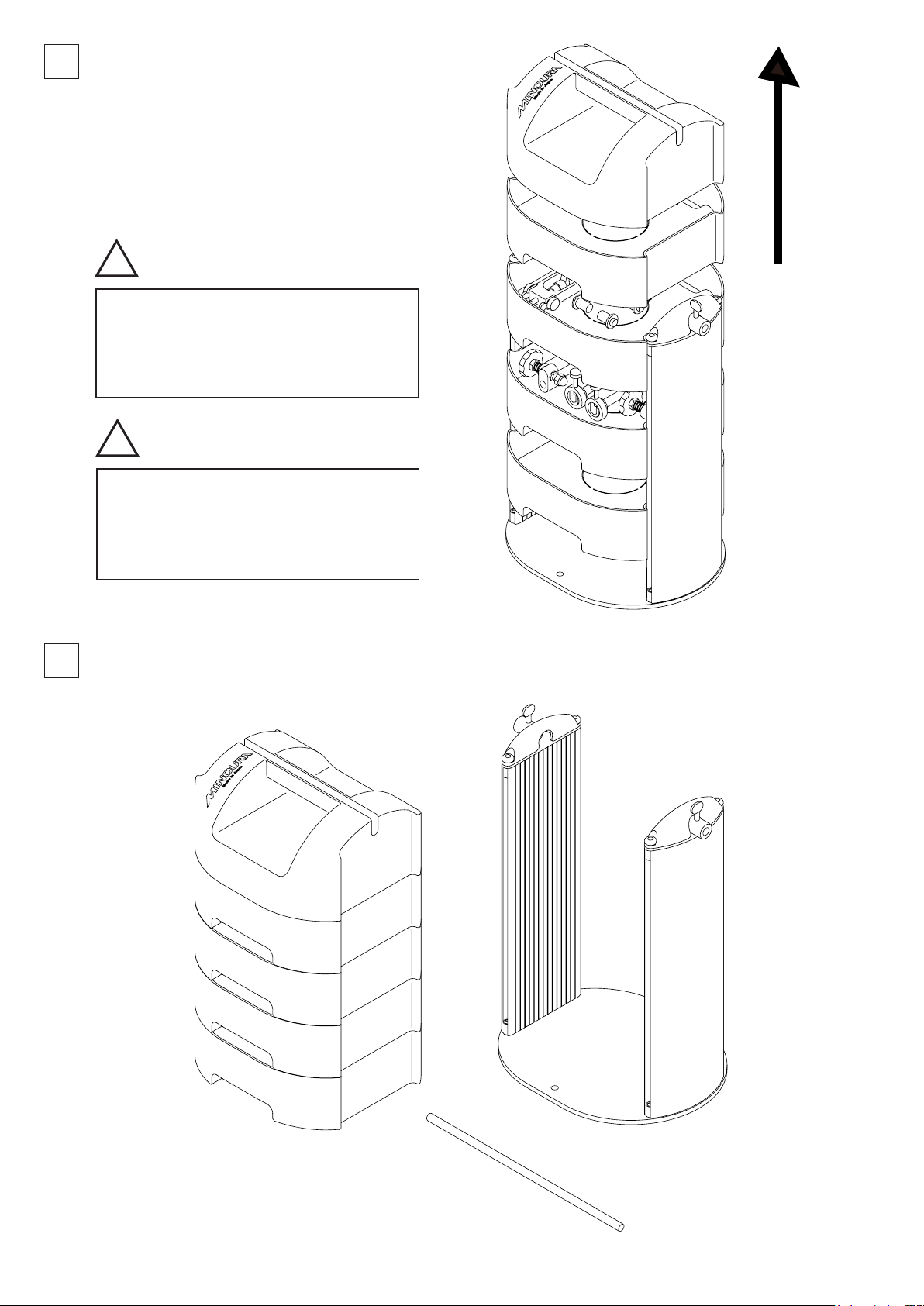
There is a total of four tool boxes stacked on
!
!
2
top of each other. They can be removed by
lifting them upward. (Fig. B)
You will see all necessary parts and adapters
in the boxes.
Also you can use this space for storing your
own parts and tools.
The boxes are not connected.
You need to pull them out one by
one, or grab the bottom box to lift
all boxes up together.
You must stack every box tightly as
the bottom rib is completely hidden
in the lower box, otherwise the xing
rod cannot be set in the last step.
After removal of all boxes, you will install the gauges
3
and coupling shafts onto the body.
(Fig. B)
(Fig. C)
- 3 -
Page 4

4
!
All 4 boxes are exactly the same.
To store a lubricant can or long tools such
as a spanner or screwdriver, cut the center
section of the cushion pad to make a hole,
and put the tool into the hole.
Please note that it's difcult to repair
the cushion if you modify it. Think
carefully before cutting the cushion
about your future needs.
Tool BoxCushion Pad
(Fig. D)
5
TIPS:
(Fig. E) (Fig. F)
Coupling Shafts,
Vertical & Horizontal Shaking Gauge
Install the coupling shafts on top of the pillars, and
set the coupling ring on each coupling.
The body is symmetric and the coupling shafts are
exactly the same.
We are installing the spring on the rigjt side coupling
in this manual. Of course, setting on left side is no
problem.
Insert a coupling shaft in the spring and set in the
hole on the right side pillar. Tighten the butterfly bolt
temporarily. (Fig. G)
On the left side, the coupling shaft doesn't have a
spring.
About Lever Bolt
Gauge Base,
Thru Axle Adapters (12mm & 15mm)
The lever bolt has a spring inside between the
threaded bolt and the lever. You are free to set
the lever at any angle as you want by pulling the
lever while turning.
To fix the gauge base, turn the lever to tighten,
pull the lever to get back to the previous angle,
and repeat the steps to tighten more.
- 4 -
(Fig. G)
Page 5

Install the gauges to the pillar rail.
!
!
6
Remove the mounting brackets from the gauge base, and put it into the pillar rail (Fig. H).
Flip the bracket vertical to insert (Fig. I), and flip horizontal back to hold (Fig. J).
1 2 3
(Fig. H)
Sandwich the gauge base with the brackets
7
from top and bottom, and screw the metal
knob bolts to mount.
The gauge base will be held in position by
screwing the inside
lever bolt which
pushes toward the
wall.
You will change the
gauge position
later, so you don't
need to tighten the
lever bolt so firmly
yet.
Gauge Base
8
Lever Bolt
Mounting
Bracket
Metal Knob Bolt
Horizontal Shaking
Gauge
(Fig. I) (Fig. J)
There is some clearance between the
bracket and the rail. That means the
gauge base may not be xed in exactly
the right angle to the pillar. Even if it's a
little slanted, it's no problem.
Screwing the lever bolt will pull the
gauge base against the pillar and holds
the gauge base solidly.
However, tightening excessively will
(Fig. K)
cause damage to the alloy rail tips and
may cause the unit to not work properly.
Do not over tighten the bolt.
Insert the side shaking
gauge unit to the gauge
shaft. (Fig. L)
9
Then insert the shaft to the
gauge base. (Fig, M)
The gauge position will
be adjusted later after
mounting the exact wheel.
We suggest you to put a
mark on the pillar to set
the gauge in right position
again easily.
Vertical Shaking
Gauge
(Fig. L)
(Fig. M)
- 5 -
10
Assembly completed. (Fig. N)
(Fig. N)
Page 6

How To Mount Wheel
!
9mm Quick Release Skewer Hub 12mm / 15mm Thru Axle Hub
Remove the Q/R.
Install with the hub
ONLY.
Conrm if the wheel
is set exactly vertical
without any backlash.
Thru Axle Adapter
(supplied)
(Fig. O)
Twist the couplings as the open side faces top, and set the wheel as both side couplings clamp the hub.
After clamping, tighten the butterfly bolt on the top cover to fix the position. (Fig. O)
It's crucial that each hub end sits in the deepest position in the coupling that makes both right and left
ends are set in the same height. This is critical in order to expect the correct result. For this purpose,
you should tighten the metal knob bolt on the coupling guide ring to push down and hold the hub axle.
In case of thru axle hub, insert the supplied adapter in the hub hole before mounting. (Fig. P)
(Fig. P)
TIPS!
Make sure there is a spring in the right side couping shaft. The spring helps push the hub towards the
clamp for a better fit.
Temporarily hold the right side coupling as the spring is compressed, place the wheel, and set the left
side coupling position. This means even if you loosen the metal knob bolt on the right side coupling,
it still continues pushing the hub.
This is also good to know if the wheel is finished symmetrically by flipping the wheel while retracting
the right side coupling only (do not move the left side coupling).
It's almost the same as when you use a dishing tool.
- 6 -
Page 7

X
How To True The Wheel
Adjust both the side coupling shaft lengths equally in order to get the wheel in the center of the stand as
closely as possible. Tighten the left side butterfly bolt firmly and tighten the right side bolt gently.
At first, loosen the butterfly bolt on the gauge base to set the vertical shaking gauge to the rim edge as close
as possible.
(Make sure you remove the tire from your wheel when checking vertical shaking.)
Next, set the horizontal shaking gauge as close as possible to the rim wall.
Tighten every butterfly bolt and metal knob bolt to fix the positions.
You should check the horizontal shaking at the area where the brake shoe touches the rim. This area is
resistant to scratching.
If your rim has a shallow wall like disc brake rims, it may be difficult to keep the rim from being scratched.
Carefully choose the right areas for contact.
If the wheel has a tire and it has contacted with the gauge or shaft, or the gauge tip cannot reach the rim,
you need to remove the tire from the rim.
Rotate the wheel slowly, and try to listen for small scratching sounds that the gauge touches the rim surface.
If the contact is too hard, turn the plastic knob bolt counter-clockwise to retract the gauge.
Adjust the gauge position so it sometimes touches the rim, not often. As the job proceeds, you need to
change the gauge position closer and closer, and in the final stage, you will see the gap between the gauge
and the rim visually, and you won't hear any more scratching sounds.
Here both side
couplings are set in
the correct position
and the wheel is
perfectly vertical.
Here the hub end
height is different
and you can see the
wheel is slanted.
(Fig. Q)
(Fig. R)
- 7 -
Page 8

If you hear the scratching sound, it means the rim has been deformed toward the gauge.
Loosen or tighten the spoke nipples to adjust the rim shape to a perfect disc.
Continue checking the gap between the gauge and the rim carefully, and when there are no more
sounds during rotations, the adjustment is complete.
In the side shaking adjustment, you should sometimes attach the Dishing Tool to know if the wheel
is symmetric.
Direct Mounting
You can fix the FT-50W to your work bench
directly with M8 bolts if you need a more solid
base. (Fig. S)
The hole pitch is 190mm.
Optional Item
The vertical and horizontal shaking gauge can be upgraded to a micro meter.
This allows you to distinguish the wheel shaking in the level of 0.1mm.
(Fig. S)
- 8 -
 Loading...