

Page 1
Wheel Truing Stand
FT-1
instructions manual
(Ver.2.1 2014/6)
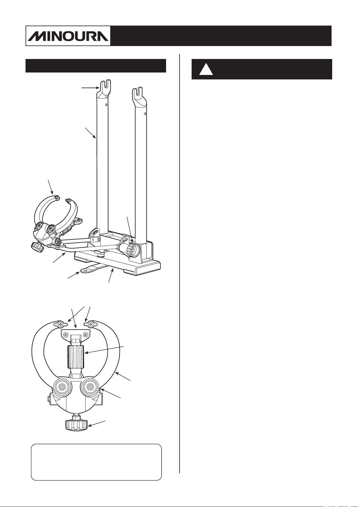
Components
Axle Holder
Pillar
Gauge Arm
Locking
Knob
Important Notes
!
• Turing wheels is done at your risk. Minoura
is not liable for any damage that may be
caused by improper use of the stand.
Wrong wheel adjustment may cause poor
brake performance or spoil bike stability.
You can use FT-1 only when you accept
this caution. And Minoura will understand
you accept this caution when you start
using FT-1.
• Only use the FT-1 to true bicycle wheels
and for no other purpose.
• FT-1 will work with 9mm quick release
skewers and xed nut axels, too.
15mm / 20mm thru axle can be used when
using optional adapters. Any other size
thru axle will not t to FT-1.
Gauge
Stay
Anti-Rolling Leg
Vertical-Shaking
Gauge
Body
Side-Shaking Gauge
Vertical Gauge
Adjust Knob
Arm
Arm Lock
Side Gauge
Adjust Knob
(Fig. A)
(Fig. B)
• Both pillars are constructed to move
together. This helps to readjust the gauge
position when changing to a different hub.
This is NOT an "Auto-Centering" feature.
You must use a wheel dishing tool to
check wheel symmetry.
• When mounting a wide hub and tightening
the skewer, the wheel may not seat
correctly because the axle holders are
angled.
Push down the wheel to set it in the deep-
est position on the Axle Holder when you
tighten the quick release skewer.
• You will use only one Side Shaking Gauge
when checking the wheel. Widely open and
lock the gauge arm which you don't use.
When you need to order replacement parts,
refer the schemastics on the last page then
order it with the correct part number or part
name.
- 1 -
Page 2
Side Shaking Gauge
Side Shaking Gauge is for checking the horizontal
movement of the wheel.
The purpose of this job is making the distance
(gap) between the rim surface and the brake shoe
equal on all around the wheel in order to expect
greater brake performance.
This job can be accomplished with the tire on or
off the wheel.
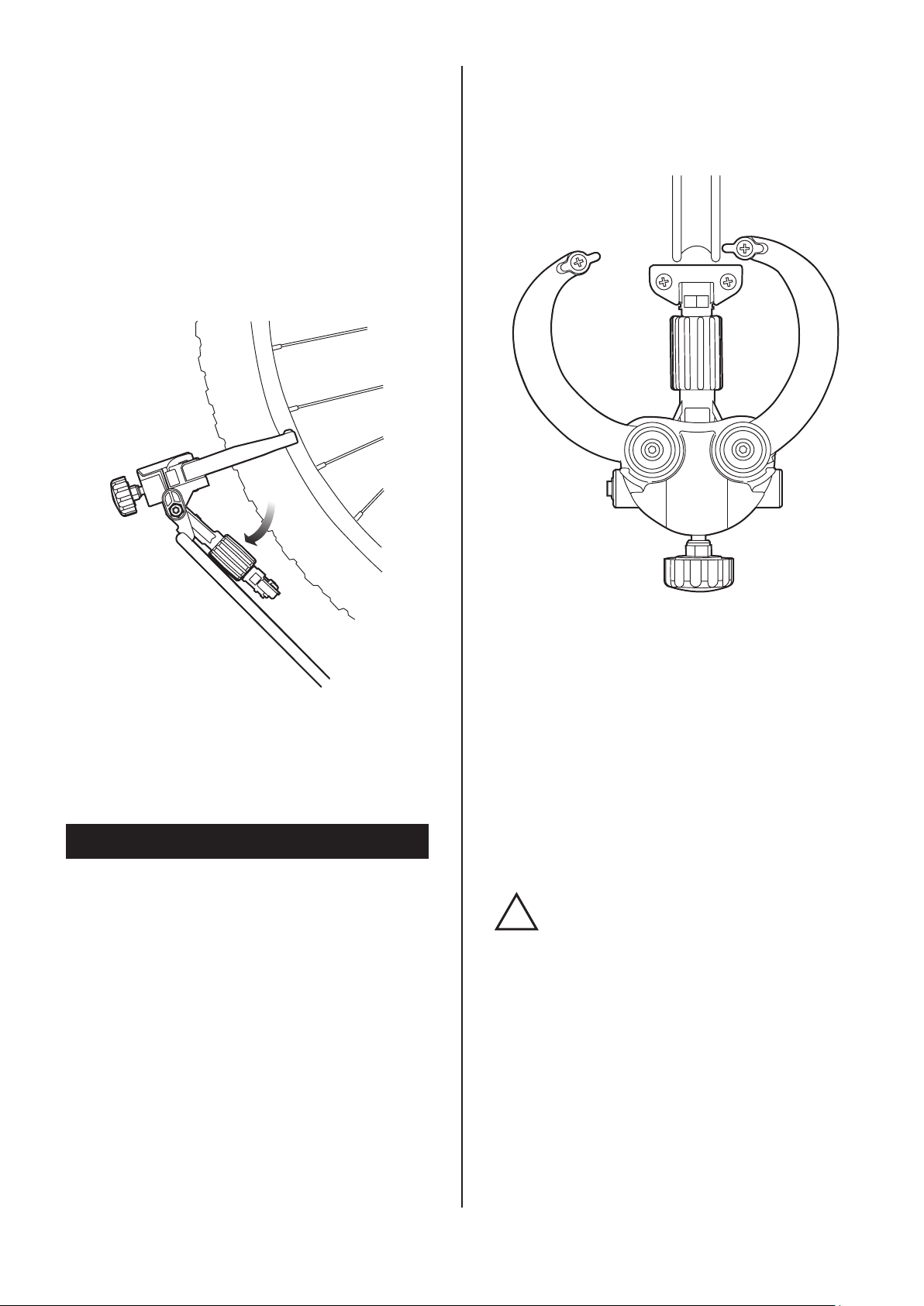
Set the wheel on the stand and position the tip of
the Side Shaking Gauge 1 - 2mm away from the
rim surface (do not touch). (see Fig. C)
Rotate the wheel slowly (do not spin fast) and look
at the clearance between the rim surface and the
gauge tip. The gap will change vary and when the
rotating wheel comes in contact with the gauge,
you will hear a scratching sound.
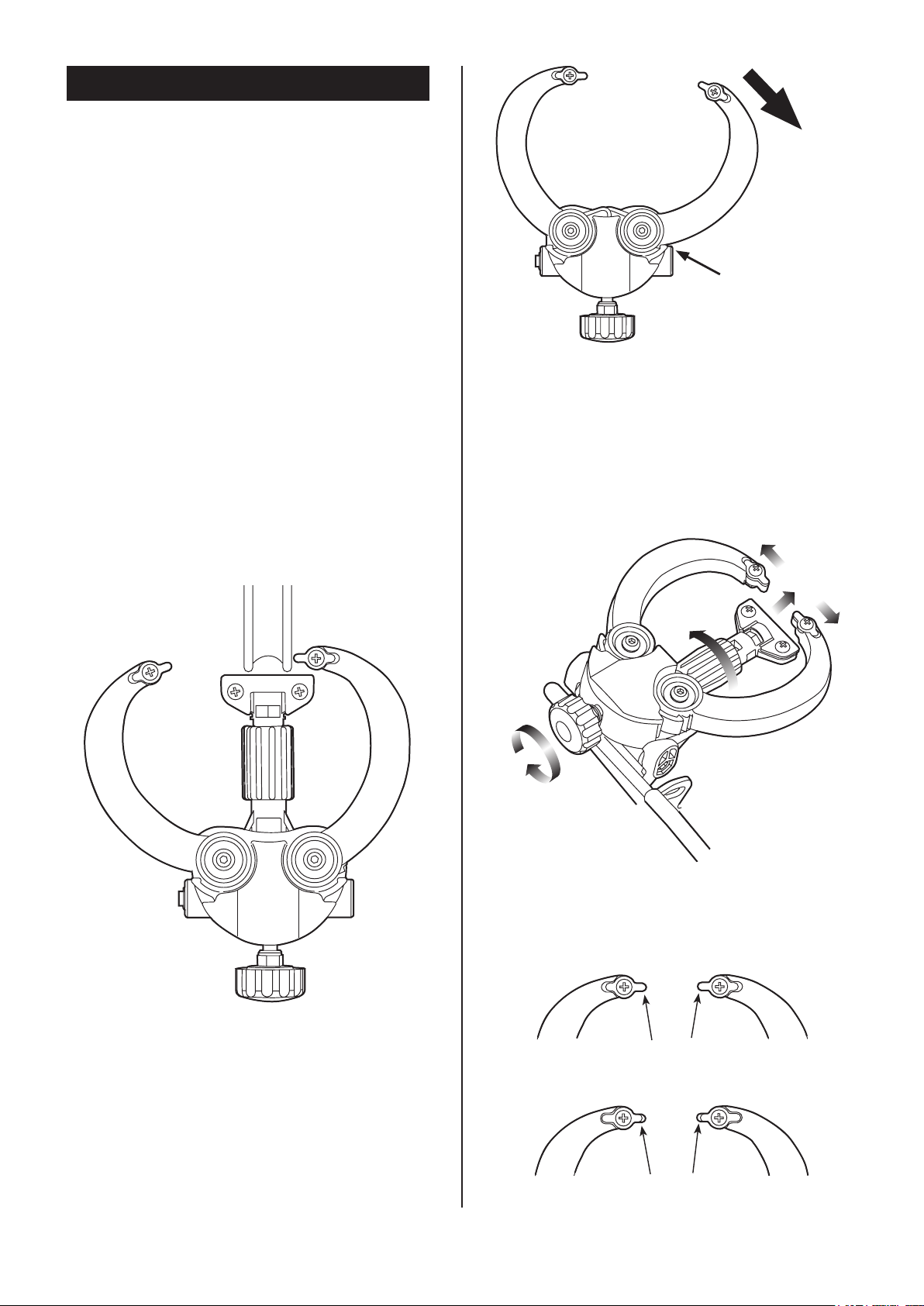
Widely open the
arm until it's caught
by the locking ratch
(Fig. D)
The side shaking gauge arm can be locked in
widely open position.
Hold the arm and move open. When the arm is
caught by the locking ratch, you will feel click.
This is the locking position. (see Fig. D)
Do not force to open more.
To close the arm, push it inward.
Turn the nipples to make this gap equal on all
around the wheel.
(Fig. C)
(Fig. E)
Turn the Side Gauge Adjust Knob, then both
arms move together. If the arm is in locked
position, it won't move even you turn the knob.
In case that you see the wheel from right hand side
to true the wheel.
On side shaking truing job, you use either right
or left side gauge. You will not use both gauges at
once.
Depends on your dominant eye, use the gauge
arm on your favorite side.
Fig.C shows then case you are dexitral.
- 2 -
Metal Rim Position
(metal tip is projected)
Carbon Rim Position
(metal tip is retracted)
(Fig. F)
Page 3
Turing wheels means the gauge has to touch the
rim and this may cause some light scratching.
the rotating wheel comes in contact with the
gauge, you will hear a scratching sound.
If you use an expensive carbon rim and you don't
want to scratch it, flip the metal piece on the Side
Shaking Gauge. In this position, only the plastic
arm body contacts the rim and it won't damage
the rim. (see Fig. F)
The contact sound between the tool and rim will
become fainter and more difficult to hear.
Turn the nipples to make this gap equal on all
around the wheel.
(Fig. H)
(Fig. G)
The angle of the gauge arm should be set as deep
as possible. (see Fig. G)
If the Vertical Shaking Gauge touch the tire, fold
it down or remove the tire.
Vertical Shaking Gauge
Vertical Shaking Gauge is for checking the vertical
movement of the wheel.
The purpose of this job is making the wheel
concentric circle to make the riding smoother.
You must remove the tire from the wheel when
doing this job.
Raise up the Vertical Shaking Gauge Arm (and
extend the arm length by turning the center barrel
type knob if necessary) to position the tip 1 - 2mm
away from the rim edge (do not touch). (see Fig. H)
The gauge arm angle against the rim should be as
deeply as possible.
Turing wheels means the gauge has to touch the
rim and this may cause some light scratching.
If you use an expensive carbon rim and you don't
want to scratch it, remove the metal bracket from
the Vertical Shaking Gauge and only the plastic
part contacts the rim.
Be sure the contacting sound will have to become
very small and difficult to listen.
If the Vertical Shaing Gauge has been
!
twisted by some reason, it will contact
only either edge of the rim.
Even in this condition, you can
continue the wheel truing job without
any problem, but if you want to have
the gauge contacts both edges at
once, twist the gauge.
Rotate the wheel slowly (do not spin fast) and
look at the clearance between the rim edge and
the gauge tip. The gap will change vary and when
- 3 -
Page 4

How To Fold Down
Pillars
To open or close the pillars, hold them with both
hands and move at once.
If you move just one side pillar or push or pull
the pillar to different direction, your FT-1 should
be deformed.
This will cause a serious problem that FT-1 no
longer holds the wheel in proper angle and you
cannot expect correct result from wheel truing job.
(Fig. I)
FT-1 is completely foldable for easier transportation and compact storage.
To fold down, follow the steps;
1. Shut the Side Gauge as narrow as possible.
(if you don't want to change the gauge
clearance, you can leave it in current position)
2. Close the pillars by pushing inward from both
sides at same time.
3. Loosen the Lock Knob.
4. Fold the gauges
Pillars.
5. Tighten the Lock Knob.
6. Turn the Anti-Rolling Leg to store under the
body, then tighten the triangle head knob bolt.
Be careful not to pinch your ngers
!
between the body and stay.
Do not try to store the gauge bet-
!
ween the pillars.
If strong sideward shock is applied,
the plastic gauges should be broken.
downward
and push toward the
About Anti-Rolling Leg
Steps of Wheel Truing Job
Usually, wheel truing job is done with the
following steps.
Different job step may force you to re-adjust
the point you already done and it will take time
longer.
You need to think about the jobs totally. You
should not focus on just one point.
1. Vertical shaking adjustment
↓
2. Side shaking adjustment
↓
3. Wheel symmetry check & Off-set
adjustment
↓
4. Spoke tension adjustment
You need to have a long fuse. Wheel truing job is
quite difficult for beginners and you should not
expect right result from just one action.
If you feel that you cannot finish it by yourself, it's
highly recommended to ask to a professional or
well-skilled mechanics.
Some shaking on the wheel is not problem for
your daily use, but be careful about the spoke
tension. Bad adjustment will cause serious
accident.
You will see a retractable leg underneath the FT-1
body. This is for preventing the rolling down
problem due to the worse balance when a wheel sits
on the stand.
The hole on the leg is xing FT-1 on your workbench
with a screw.
To retract the leg, loosen the triangle knob bolt, ip
out the leg, then tighten the knob again.
- 4 -
Page 5

About Offset Wheel Setting
How To Fix Vertical Movement
At rst, you should understand that you should
x the vertical movement prior to the horizontal
movement, especially on the rear wheel because of
its unique wheel system named
Offset Wheel
Tensioning the front wheel is much easier than
the rear. Rear wheel tensioning requires Offset
Tensioning.
The rear wheel has a different spoke angle pattern
when looking at it from behind. (see Fig. J)
A rear hub is not symmetrical to the wheel. Flanges
can be far from center. Because the rear hub must
have extra space for the set of transmission gears,
you will need to true using Offset Tensioning.
"Offset"
.
(Fig. J)
The vertical movement within 3 mm may not
cause any troubles. But if you want to be it as zero
as possible for smoother ride, you should try the
following process again and again.
Be sure, in this case, you should tighten both side of
the nipples equally.
1.
You set the wheel on the FT-1 and see the Vertical
Gauge.
Put the tip of the Vretical Gauge close to the surface
of the rim.
2.
Rotate the wheel slowly, and check the vertical
movement. Do not spin fast.
3.
Attach tapes to two spokes; one is in the beginning
and another one is in the ending of vertical
movement.
4.
Make three (3) groups of spokes between your tape
markers as below;
If offset wheel, the torque works mostly only to
the right side (gear side) spokes. Because right side
spokes should be assembled more vertically than left
side.
Understand that right side spoke tension is more
important than left side spoke's one in this offset
assembling.
Well adjusted right side spokes can keep your wheel
stable in the future. Left side spoke tension is just a
help.
The nipple should not be loosened at any time.
Nipples are made from softer alloys or brass and are
prone to stripping easily.
You must use a correct spoke wrench
!
which ts the nipples perfectly,
especially when you use light alloy
nipples on your wheel.
If you use wrong size one, the nipple
will become round easily and you
cannot continue your work any more.
A
B
C
B
A
Group-A:
Group-B:
Group-C:
3 or less spokes in the beginning and in
the ending of vertical movement.
3 or less spokes between Group-A,
except for the center spoke.
The center 1 or 2 between the tapes.
5.
If the rim moves to outward, tighten both side
nipples.
- 5 -
(Fig. K)
Page 6

If the rim shakes inward, do NOT try to loosen the
nipples. Tighten both far side nipples.
This is because the nipples are made of soft material,
so its thread can be broken easily by loosening.
6.
Tighten the spokes as below;
• Group-B nipples = about 1/4 turns
• Group-C nipples = about 1/2 turns
Then check the vertical movement again with
rotating the wheel slowly.
If the wheel moves yet, continue the process again.
• Group-A nipples = about 1/8 turns
If you hear a strange sound or see
!
narrow metal "lines" or residue, your
nipple will fail soon.
Do NOT apply any lubricant to quiet
the sound. Put a new nipple on
immediately.
Group-A:
Group-B:
Group-C:
3 or less spokes in the beginning and in
the ending of horizontal movement.
3 or less spokes between Group-A,
except for the center spoke.
The center 1 or 2 between the tapes.
5.
If the rim moves to right, tighten the left side nipples.
Do NOT loosen the right side nipples.
This is because the nipples are made of soft material,
so its thread can be broken easily by loosening.
6.
Tighten the spokes as below;
• Group-B nipples = about 1/4 turns
• Group-C nipples = about 1/2 turns
Then check the horizontal movement again with
rotating the wheel slowly.
• Group-A nipples = about 1/8 turns
Do NOT tighten the spoke more
!
than 1/2 turns at one time. Wheel
truing must be done step by step.
Otherwise, you will loose the spoke
tension balance completely.
How To Fix Horizontal Movement
The horizontal movement within 2 mm may not
cause any troubles. But if you want to be it as zero
as possible for smoother ride, you should try the
following process again and again.
1.
You set the wheel on the FT-1 and see the Side
Gauges.
Put the tips of them close to the surface of the rim
side wall. Do not make them touch the rim.
2.
Rotate the wheel slowly, and check the horizontal
movement. Do not spin fast.
3.
Attach tapes to two spokes; one is in the beginning
and one is in the ending of horizontal movement.
If the wheel moves yet, continue the process again.
If you hear a strange sound or see
!
metal "lines" or residue, your nipple
will fail soon.
Do NOT apply any lubricant to quiet
the sound. Put a new nipple on
immediately.
Do NOT tighten the spoke more
!
than 1/2 turns at one time. Wheel
truing must be done step by step.
Otherwise, you will loose the spoke
tension balance completely.
There are several ways to true the
bike wheel, and there are many spoke
crossing patterns available depends on
the purpose on wheel.
Above is just one example and you don't
have to follow our way.
You should refer a bike maintenance
guidebook or ask to well-educated
mechanics to learn more effective
techniques.
4.
Make three (3) groups of spokes between your tape
markers as below;
- 6 -
Page 7

Limited Warranty Policy
For More Information...
Minoura offers -year limited warranty on this product
under the following conditions;
1. Only the original user who purchased this FT-1 in brandnew and unopened condition at an authorized Minoura
dealer, authorized internet retailer or authorized mail order
house (hereafter "Original User") is covered under the
Minoura Warranty Service Program (hereafter "Warranty
Service").
2. Any used or new FT-1, either purchased or given
through a shop, internet auction site or person-to-person
will NOT be covered under Warranty Service, except under
special circumstances to be determined by Minoura.
3. Original User must keep the original sales reciept and
must present a photocopy of the reciept together with a
claim report to obtain Warranty Service.
4. The warranty period shall start from the date of
purchase. If the reciept is not presented, Minoura reserves
the right to extend or deny Warranty Service.
5. All warranties will be void if the FT-1 is damaged due
to user's abuse, disassembly, unauthorized alteration or
midication, or used in any way not intended as described
in the instructions manual.
* When you need help, please contact
the shop rst where you purchased FT-1.
MINOURA Japan Headquarters
(for ALL customers)
1197-1 Godo, Anpachi, Gifu 503-2305 Japan
Phone: +81-584-27-3131
Fax: +81-584-27-7505
Email: minoura@minoura.jp
URL: www.minourausa.com
MINOURA North America
(for U.S. residents only)
California, U.S.A.
Phone: 1-510-538-8599
Fax: 1-510-538-5899
Email: support@minourausa.com
** For countries not listed, please see
our web site at www.minoura.jp to
nd the Minoura distributor in your
country and contact them for service.
Made in Japan
6. Only issues caused by manufacturer's defects will be
covered to all users at Minoura's expense. The period
expires in a maximum of 7 years after the last production.
7. Minoura may offer paid service for in or out of warranty
products that may include, but is not limited to, repair,
replacement and shipping expenses.
For more detailed information, refer both the
attached "MINOURA LIMITED WARRANTY
POLICY" card and our web site (http://www.
minourausa.com).
Web can offer you the latest and more correct
information.
- 7 -
Page 8

FT-1 Schematics
Screw M4x12
TG-6
TG-7
Cap Bolt M5x25
TG-1
Tapping Screw M3.5x12
TG-9
TG-8
M5 Flat Washer
TG-5
Screw M4x10
FF-5
TG-3
TG-4
TG-2
M5 Spring Washer
Cap Bolt M5x10
PARTS CODE
FF-1: FT-1 Main Body
FF-2: Base End Cap
FF-3: Anti-Rolling Leg
FF-4: Triangle Knob Bolt
FF-5: Axle Holder
TF-4: Lock Knob
TG-1: Gauge Body
TG-2: Vertical Gauge
TG-3: Vertical Gauge Plate
TG-4: Arm (Right)
TG-5: Arm (Left)
TG-6: Side Gauge Plate
TG-7: Upper Cover
TG-8: Spring (Right, Silver)
TG-9: Spring (Left, Black)
FF-2
FF-4
FF-3
TF-4
FF-1
FF-2
Tapping Screw M5x10
Page 9

FCG-310
This is the instructions for the tools contained in the
FCG-310
wheels between 18" and 27"/700c (applicable rim diameter : 335mm – 655mm).
NW-300
Please read this instructions manual carefully before use to understand how you will do on your bicycle wheel.
is the tool to check if the wheel is exactly symmetrical for better ride. You can use FCG-310 on most size of
is the spoke nipple wrench for twisting nipples on 14G/15G spokes.
FT-1 Combo
&
NW-300
kit.
instructions manual
(Ver.1.1 2014/6)
Knob Bolt
<FCG-310>
IMPORTANT NOTES
FCG-310 is the measuring gauge for bicycle wheel only. Do not use it for any other purpose than
!
!
!
!
instructed.
FCG-310 is a precision tool so please handle it with care. Do not hit or bend the frame and gauge
plate.
Be careful not to pinch your ngers when openning or closing the FCG-310.
Insert the NW-300 fully to the nipple when tightening. Use exactly same size of wrench without any
wag to protect the nipple. The size indication is just for your reference.
Frame
Gauge Plate
Ratch
Rim Guide
Positioning Lib
<NW-300>
15G
14G
15G
14G
How To Use FCG-310
1.
2.
3.
4.
5.
To open the FCG-310, loosen the Knob Bolt then open the Frame with both hands.
Look for the grooves on the inside of the Ratches that fix the angle when the Frame is opened.
Extend until the grooves meet and lock into place by pushing them each other.
Turn the Gauge Plate counter-clockwise to locate the hole at the down end side.
Put the Gauge Plate on the flat groove on the outside of the Ratch.
Tighten the Knob Bolt, but you don't need to tighten it so firmly at this moment.
If the Gauge Plate doesn't t to the at
groove on the Ratch correctly, you won't
!
be able to measure properly. And also the
Gauge Plate will have to be bent.
Please be sure that the Gauge Plate cannot
be replaced.
Attach the FCG-310 to the wheel as shown in Fig. A.
While keeping both Rim Guides touching the rim, loosen the Knob Bolt to slide down
the Gauge Plate, then tighten the Knob Bolt firmly to record the triangle point.
(Fig. A)
At this moment, make sure the following points;
• Both Rim Guides touch the rim.
!
• The wheel axle is running through the hole on the Gauge Plate, and the Gauge Plate touches the
hub.
Page 10

6.
Flip over the wheel and attach the FCG-310 onto
the opposite side of the wheel. Do not change the
Gauge Plate position yet.
At this time, if all three points (both Rim Guides
and the tip of the Gauge Plate) touch each
appropriate position at once on both side of
the wheel (see Fig. B), your wheel is properly
assembled and adjusted.
But if either one of the Rim Guides or the Gauge
Plate doesn't touch the appropriate position (see
Fig. C), your wheel needs to be adjusted further.
If the Rim Guide doesn't touch the rim, the wheel
has been moved toward opposite side.
If the Gauge Plate doesn't touch the hub even
though both Rim Guides touch the rim, your wheel
has been moved backward.
Set the wheel on the wheel truing stand to adjust. To know how to adjust the wheel, refer the instructions manual
of the truing stand.
It is crucial to measure the wheel at several different points to get proper result.
!
Properly Adjusted
(Fig. B)
Wrong Adjsuted
(Fig. C)
Useful Additional Features
FCG-310 can be used on most wheels sized between 24" and 27"/700c in the standard position.
In addition, you can use it for the smaller wheel (18" or larger) and the wide (up tp 140mm) hub wheel which is used on
some DH, FR and city commuting bikes by changing the the Rim Guide position. (see Fig. D & E)
<To Measure Smaller Wheel>
Make both Rim Guides inward
<To Measure Wide Hub>
Step down both Rim Guides
(Fig. D)
The hole must be outward
(Fig. E)
How To Fold Down FCG-310
To fold down the FCG-310, 1) loosen the Knob Bolt fully,
2) separate the Ratches as if pulling outward on each other, 3) rotate
the Gauge Plate as the hole faces outward, then 4) fold the Frame.
Do not tighten the Knob Bolt while the hole of the Gauge
!
Plate is facing inward, otherwise the Gauge Plate will be bent.
Please be sure the Gauge Plate cannot be replaced.
How To Use NW-300
Insert the wrench of the NW-300 to the nipple fully to the bottom. Do not use any incorrect (wider) size wrench. Tighten
the nipple slowly. You must stop tightening after turning 1/2 rotation at once at widest. These are for protecting the
nipple from damage. Once the nipple is damaged, you won't be able to continue any work on wheel.
Do not continue using the NW-300 if its jaws don't t
!
your nipples. Use another nipple wrench.
(Fig. F)
 Loading...