

Page 1
eRDA-850LW series indoor bicycle trainer
instructions manual
- 1 -
Page 2
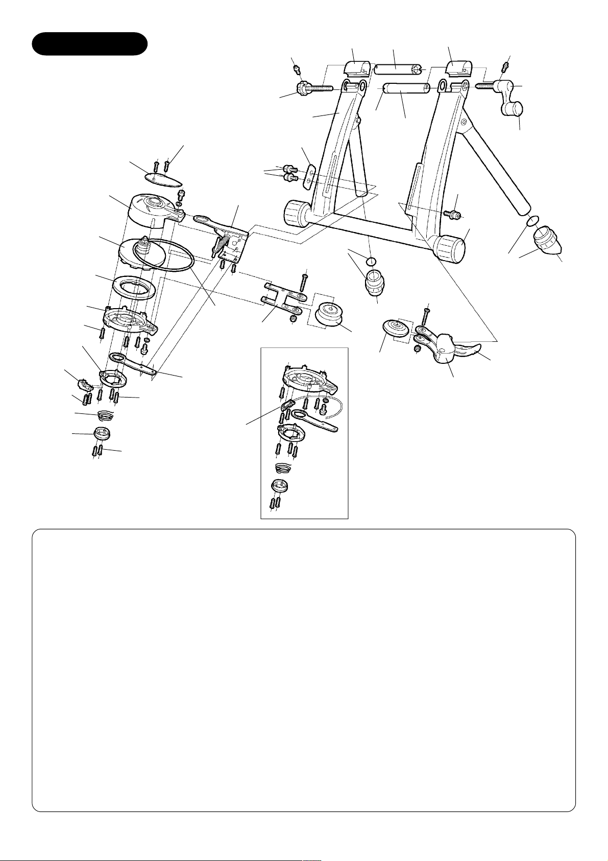
SCHEMATIC
F-8
F-4
F-2
F-4
ER-2
Screw-L
ER-4
ER-5
Screw-S
ER-9
ER-6
ER-1
ER-7
ER-8
ER-3
Screw-M
SR-5
ER-11
Screw w/ washer
ER-15
SR-12
ER-10
ER-12
R8-1
SR-13
M8-4
SR-7
F-9
SR-8
F-1
F-7
SR-12
M8-3
M8-4
ER-14
ER-13
Screw-M
<Remote Version>
F-1 : Coupling (Right) ER-1 : Upper Case
F-2 : Coupling (Left) ER-2 : Lower Case
F-4 : Coupling Cover (move side) ER-3 : Top Cover (blue)
F-7 : Hub Handle (3/8” thread) ER-4 : Magnet Guide Ring (blue)
F-8 : Wheel Position Adjust Knob ER-5 : Dial Lever (blue)
F-9 : Hub Nut Protector (Grommet) ER-6 : Spring Holder
R8-1 : RDA-850 Main Frame ER-7 : Flywheel, Alloy Rotor & Axle
M8-3: Rubber Frame Cap (38.1mm) ER-8 : Magnet
M8-4: Rubber Foot Cap (31.8mm) ER-9 : Spring
SR-5 : V-Belt (K-16) ER-10 : Main Arm
SR-7 : Drive Roller Pulley ER-11 : Sub Arm
SR-8 : Assistant Roller Pulley ER-12 : Pulley Arm
SR-12 : Cap Bolt (M6x12) ER-13 : Assistant Pulley Holder
SR-13 : Reinforcement Plate ER-14 : Tension Lever
ER-15 : Remote Bracket & Cable
- 2 -
Page 3
IMPORTANT NOTES
• Read all instructions carefully before use.• Read all instructions carefully before use.
• Read all instructions carefully before use.
• Read all instructions carefully before use.• Read all instructions carefully before use.
• Some assembly required.• Some assembly required.
• Some assembly required.
• Some assembly required.• Some assembly required.
• Keep the manual handy at all times.• Keep the manual handy at all times.
• Keep the manual handy at all times.
• Keep the manual handy at all times.• Keep the manual handy at all times.
• Do NOT use trainer for any other purpose than instructed.• Do NOT use trainer for any other purpose than instructed.
• Do NOT use trainer for any other purpose than instructed.
• Do NOT use trainer for any other purpose than instructed.• Do NOT use trainer for any other purpose than instructed.
• The trainer is manufactured to precise standards. Disassembly may void your warranty.• The trainer is manufactured to precise standards. Disassembly may void your warranty.
• The trainer is manufactured to precise standards. Disassembly may void your warranty.
• The trainer is manufactured to precise standards. Disassembly may void your warranty.• The trainer is manufactured to precise standards. Disassembly may void your warranty.
• "Magturbo" and “RDA” are the trademarks of Minoura Co.,Ltd. and may not be copied.• "Magturbo" and “RDA” are the trademarks of Minoura Co.,Ltd. and may not be copied.
• "Magturbo" and “RDA” are the trademarks of Minoura Co.,Ltd. and may not be copied.
• "Magturbo" and “RDA” are the trademarks of Minoura Co.,Ltd. and may not be copied.• "Magturbo" and “RDA” are the trademarks of Minoura Co.,Ltd. and may not be copied.
WARNINGS
Use two-wheeled bicycles only. Tandems may be used if balanced correctly.Use two-wheeled bicycles only. Tandems may be used if balanced correctly.
Use two-wheeled bicycles only. Tandems may be used if balanced correctly.
Use two-wheeled bicycles only. Tandems may be used if balanced correctly.Use two-wheeled bicycles only. Tandems may be used if balanced correctly.
!
You may use the quick release skewer currently on your bicycle, however we recommend replacingYou may use the quick release skewer currently on your bicycle, however we recommend replacing
You may use the quick release skewer currently on your bicycle, however we recommend replacing
You may use the quick release skewer currently on your bicycle, however we recommend replacingYou may use the quick release skewer currently on your bicycle, however we recommend replacing
!
your quick release skewer with the one supplied and install the coupling protector cap on to theyour quick release skewer with the one supplied and install the coupling protector cap on to the
your quick release skewer with the one supplied and install the coupling protector cap on to the
your quick release skewer with the one supplied and install the coupling protector cap on to theyour quick release skewer with the one supplied and install the coupling protector cap on to the
right side coupling of the trainer. Otherwise the stability will not be guaranteed.right side coupling of the trainer. Otherwise the stability will not be guaranteed.
right side coupling of the trainer. Otherwise the stability will not be guaranteed.
right side coupling of the trainer. Otherwise the stability will not be guaranteed.right side coupling of the trainer. Otherwise the stability will not be guaranteed.
Remove the coupling protector cap when you use your own quick release skewer.Remove the coupling protector cap when you use your own quick release skewer.
Remove the coupling protector cap when you use your own quick release skewer.
Remove the coupling protector cap when you use your own quick release skewer.Remove the coupling protector cap when you use your own quick release skewer.
!
Remove all oils and moisture from the drive roller and the tire before use.Remove all oils and moisture from the drive roller and the tire before use.
Remove all oils and moisture from the drive roller and the tire before use.
Remove all oils and moisture from the drive roller and the tire before use.Remove all oils and moisture from the drive roller and the tire before use.
!
Keep both hands on handlebars at all times and maintain a normal riding position.Keep both hands on handlebars at all times and maintain a normal riding position.
Keep both hands on handlebars at all times and maintain a normal riding position.
Keep both hands on handlebars at all times and maintain a normal riding position.Keep both hands on handlebars at all times and maintain a normal riding position.
!
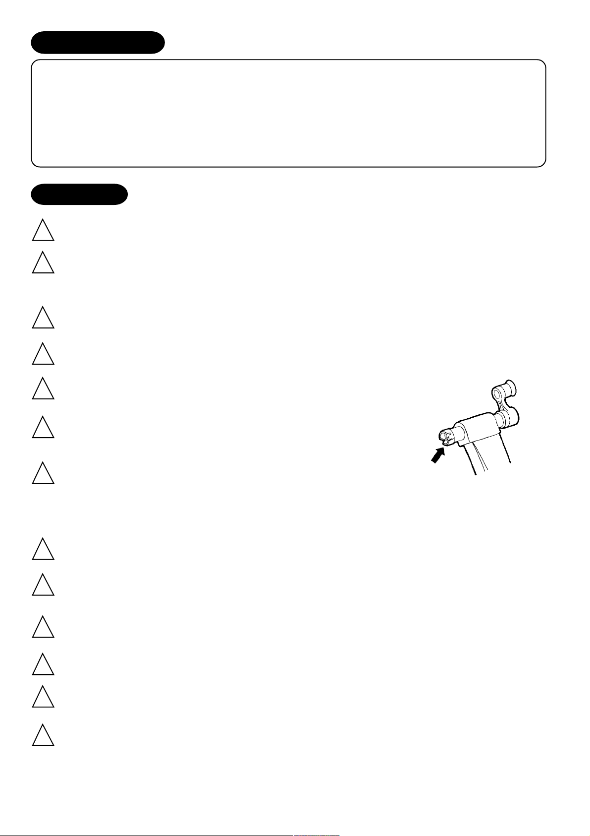
Check the couplings supporting the rear hub for damage and cracks.Check the couplings supporting the rear hub for damage and cracks.
Check the couplings supporting the rear hub for damage and cracks.
Check the couplings supporting the rear hub for damage and cracks.Check the couplings supporting the rear hub for damage and cracks.
!
Accidents may occur from cracked or damaged couplings. (Fig. A)Accidents may occur from cracked or damaged couplings. (Fig. A)
Accidents may occur from cracked or damaged couplings. (Fig. A)
Accidents may occur from cracked or damaged couplings. (Fig. A)Accidents may occur from cracked or damaged couplings. (Fig. A)
You should not tighten the wheel axle by tightening the left side knob.You should not tighten the wheel axle by tightening the left side knob.
You should not tighten the wheel axle by tightening the left side knob.
You should not tighten the wheel axle by tightening the left side knob.You should not tighten the wheel axle by tightening the left side knob.
!
This is for pre-adjusting the wheel position to the exactly center of theThis is for pre-adjusting the wheel position to the exactly center of the
This is for pre-adjusting the wheel position to the exactly center of the
This is for pre-adjusting the wheel position to the exactly center of theThis is for pre-adjusting the wheel position to the exactly center of the
drive roller only. Securley tightening your bike to the trainer should bedrive roller only. Securley tightening your bike to the trainer should be
drive roller only. Securley tightening your bike to the trainer should be
drive roller only. Securley tightening your bike to the trainer should bedrive roller only. Securley tightening your bike to the trainer should be
done with the right side hub handle only.done with the right side hub handle only.
done with the right side hub handle only.
done with the right side hub handle only.done with the right side hub handle only.
When using the trainer, place it on a flat surface for safe training.When using the trainer, place it on a flat surface for safe training.
When using the trainer, place it on a flat surface for safe training.
When using the trainer, place it on a flat surface for safe training.When using the trainer, place it on a flat surface for safe training.
!
Do not over tighten the hub-clamp handles. Over-tightening may cause damage to the trainer orDo not over tighten the hub-clamp handles. Over-tightening may cause damage to the trainer or
Do not over tighten the hub-clamp handles. Over-tightening may cause damage to the trainer or
Do not over tighten the hub-clamp handles. Over-tightening may cause damage to the trainer orDo not over tighten the hub-clamp handles. Over-tightening may cause damage to the trainer or
!
bicycle frame. The clamp handles should be a snug and secure fit. Do not force!bicycle frame. The clamp handles should be a snug and secure fit. Do not force!
bicycle frame. The clamp handles should be a snug and secure fit. Do not force!
bicycle frame. The clamp handles should be a snug and secure fit. Do not force!bicycle frame. The clamp handles should be a snug and secure fit. Do not force!
Before use, make sure all bolts and nuts are securely fastened.Before use, make sure all bolts and nuts are securely fastened.
Before use, make sure all bolts and nuts are securely fastened.
Before use, make sure all bolts and nuts are securely fastened.Before use, make sure all bolts and nuts are securely fastened.
!
(Fig. A)
Keep away from small children, and keep hands and feet away from spinning rollers and wheels atKeep away from small children, and keep hands and feet away from spinning rollers and wheels at
Keep away from small children, and keep hands and feet away from spinning rollers and wheels at
Keep away from small children, and keep hands and feet away from spinning rollers and wheels atKeep away from small children, and keep hands and feet away from spinning rollers and wheels at
!
all times.all times.
all times.
all times.all times.
Open the legs fully to get maximum stability.Open the legs fully to get maximum stability.
Open the legs fully to get maximum stability.
Open the legs fully to get maximum stability.Open the legs fully to get maximum stability.
!
Wipe all oil and moistures out from the rim surface everytime you use the trainer to keep necessaryWipe all oil and moistures out from the rim surface everytime you use the trainer to keep necessary
Wipe all oil and moistures out from the rim surface everytime you use the trainer to keep necessary
Wipe all oil and moistures out from the rim surface everytime you use the trainer to keep necessaryWipe all oil and moistures out from the rim surface everytime you use the trainer to keep necessary
!
brake performance of your bicycle.brake performance of your bicycle.
brake performance of your bicycle.
brake performance of your bicycle.brake performance of your bicycle.
- 3 -
Page 4

HOW TO SETUP YOUR E-RDA850 TRAINER
<Required Tools: M5 hex wrench>
1
2
Open the frame support legs and fit the rubber feet at the correct angle so the base is in full contact with
the floor. Do NOT remove the round metal plates from inside the rubber feet when fitting. Ensure the
rubber foot caps are facing outwards as incorrect fitting may compromise the stability of the trainer.
NOTE: If the both legs don’t touch the floor at same time and if one side of the leg is still slightly raised, pull up the
leg upward strongly then place the trainer on the floor again.
Install the Mag resistance unit on the left side slot and
the assistant roller on the right side slot beside the trainer
pillar by the supplied M6x12 bolts. (see Fig. B)
NOTE: We recommend you to use the reinforcement plate
(SR-13) for installing the Mag unit. This plate will sandwich
the slot plate from outside for mounting the heavy Mag unit
and giving it extra stability.
(Fig. B)
3
Open both couplings by turning the left side knob (see Fig. C) and the right side hub handle (see Fig. D)
anti-clockwise.
Do not over-loosen the couplings, otherwise the knob or the hub handle may become unthreaded inside
the frame.
Left Side Knob
(Fig. C)
NOTE:NOTE:
NOTE: We suggest not using the left side coupling for major adjustment. Moving
NOTE:NOTE:
it too much to one side will cause misalignment. The left side coupling is used
only to provide easy intitial adjustment for your hub length. (see Fig. E)
Right Side Hub Handle
(Fig. D)
(Fig. E)
4
Insert the left side of the skewer (Q/R lever side) into the left side coupling, and adjust the rotation of the coupling so the skewer lever sits
securely in the large cut-out (see Fig. F). This will prevent damage to the
skewer during use.
- 4 -
(Fig. F)
Page 5

5
Hold the bike firmly by hand and turn the right side hub handle clockwise until the coupling comes into
contact with the right side skewer nut.
6
7
Adjust each height of the Mag unit and the assistant
roller to fit to your rear wheel perfectly and tighten the
bolts firmly. (see Fig. G)
Each rubber roller is made to contact the rim ONLY.Each rubber roller is made to contact the rim ONLY.
Each rubber roller is made to contact the rim ONLY.
Each rubber roller is made to contact the rim ONLY.Each rubber roller is made to contact the rim ONLY.
!
Contact with the tire may cause the tire to burstContact with the tire may cause the tire to burst
Contact with the tire may cause the tire to burst
Contact with the tire may cause the tire to burstContact with the tire may cause the tire to burst
during use.during use.
during use.
during use.during use.
Adjust the wheel position by checking the double-circle
position indicators on both side.
The best position should be each indicator can be seen
equally, but if your rim is narrow, you should adjust
the wheel position to be a little left (toward Mag side)
to prevent unexpected slippage problem.
NOTE:NOTE:
NOTE: Note that the left side knob is NOT for tightening
NOTE:NOTE:
the axle. It is only for positioning the wheel. Clamping
wheel securely must be done by the right side hub handle.
(Fig. G)
(Fig. H)
USING THE PLATIC SKEWER NUT PROTECTOR
We recommend that you use the supplied skewer if at all possible. This
will gaurantee a fit with our couplings and remove any chance of misalignment.
Hole
(Fig. I)
The right side coupling has a black plastic skewer nut protector (called a “Grommet”). This is to protect your
skewer from damage during use, however, should you choose to use your own skewer, you should use the
supplied grommet to insure a better fit.
We will NOT guarantee any fitting problem or accident caused by using your own skewer on the trainer.We will NOT guarantee any fitting problem or accident caused by using your own skewer on the trainer.
We will NOT guarantee any fitting problem or accident caused by using your own skewer on the trainer.
We will NOT guarantee any fitting problem or accident caused by using your own skewer on the trainer.We will NOT guarantee any fitting problem or accident caused by using your own skewer on the trainer.
When you use the supplied skewer, you should remove the grommet from the coupling. It can be done by
inserting a rod or a pen to the hole (see Fig. I) and then lifting up the grommet.
- 5 -
Page 6

HOW TO INSTALL THE REMOTE LEVER
You can install the remote lever on anywhere the diameter is between 22.2mm (7/8”) and 31.8mm (1-1/4”) like
as on the handlebar.
1
2
Fully loosen the knob bolt on the plastic holder until it stops then push down the bolt to open the holder.
(see Fig. J)
Place the holder onto the handlebar, shut the holder, and pull up the bolt then tighten it. (see Fig. K)
Shim
(Fig. J) (Fig. K)
Depends on the diameter of your handlebar, you must adjust the
!
(Fig. K-2)
shim as follows;
• 22.2mm (7/8”) - 25.4mm (1”): Install both shims.
• 28.6mm (1-1/8”): Install either right or left side shim.
• 31.8mm (1-1/4”): Remove both shims.
When you install the shim
on the plastic holder, make
sure the direction of the
shim as shown in Fig. J-2.
USING THE MAG RESISTANCE UNIT
The Mag unit has 7 different levels of load force, replicating actual riding resistance.
The load settings range from high (H) to low (L) can be adjusted via the white lever on the Magturbo unit or the
lever on the thumb shifter type remote lever device. You may also adjust the load force by shifting up or down
among your gears, depending on the level desired.
We recommend that you start with a medium to low load force and gradually work
up, increasing force as your muscles warm up.
Increasing Load ForceIncreasing Load Force
Increasing Load Force
Increasing Load ForceIncreasing Load Force
To increase the load force, move the white lever on the Mag unit toward the (H)
symbol. (see Fig. L)
(Fig. L)
If your Mag unit is a remote control type, turn the lever on your thumb shifter
device toward the (H) symbol. (see Fig. N)
Decreasing Load ForceDecreasing Load Force
Decreasing Load Force
Decreasing Load ForceDecreasing Load Force
To decrease the load force, move the white lever on Mag unit toward the (L)
symbol. (see Fig. M)
Be sure the lowest selection is not zero load, there still be a small level of force.
If your Mag unit is a remote control type, turn the lever on your thumb shifter
device toward the (L) symbol.
- 6 -
(Fig. M)
Page 7

To make any adjustment to the unit, make sure you are off theTo make any adjustment to the unit, make sure you are off the
To make any adjustment to the unit, make sure you are off the
To make any adjustment to the unit, make sure you are off theTo make any adjustment to the unit, make sure you are off the
!
bike, and that the trainer has come to a complete stop andbike, and that the trainer has come to a complete stop and
bike, and that the trainer has come to a complete stop and
bike, and that the trainer has come to a complete stop andbike, and that the trainer has come to a complete stop and
that nothing is still moving.that nothing is still moving.
that nothing is still moving.
that nothing is still moving.that nothing is still moving.
TROUBLE SHOOTING YOUR REMOTE SHIFTER UNIT
(Fig. N)
If you cannot shift to either the lowest (L) or the highest (H) position, it is possible
that the inner wire of the remote shifter cable is too long and the wire tension is
Nut Plastic Cap
Cable
loose. If so, please adjust the tension with the following steps.
1
2
3
Set the remote shifter lever at “H” position. Remove the remote shifter
device from the handlebar and straighten the cable.
Remove the plastic cap located on the bottom of the cable. (see Fig. O)
Hold the adjusting screw with your right hand and push it towards the
Wire Tension
Adjusting Screw
(Fig. O)
direction of the outer cable, then adjust the nut with your left hand to make
the wire tension properly.
If you experience that the remote lever will move toward “H” unexpectedly automarically when you pedal hard,
try to tighten the adjusting screw 1/4 rotation. The screw is located under the remote lever holder.
ABOUT SLIPPAGE PROBLEM
The pateneted roller system used in the rim drive models from Minoura is made to fit a wide variety of bicycles
and wheels. Therefore, you should expect that sometimes the rollers will slip a little on your rims. This is completely normal and due to the spring mechanism we use that provides a fit with such a large variety of bicycles
and wheels.
If you experience slippage all the time you use the trainer, check the belt tension first by pushing down the belt
with your finger. The V-belt will be worn down after long term use but most reason for the slippage problem is
caused by improper (too much or too less) tension adjustment.
To adjust the belt tension, loosen both upper and lower bolts which hold the pulley arm by an M5 hex wrench,
then pull the arm outward by your hand and tighten the bolts firmly again.
If the V-belt is completely worn down or damaged, replace it.
This work requieres high skill for disassembling and assembling the Mag unit. If you don’t have confidence,
please ask to the Minoura dealer where you purchased the trainer.
The instructions manual will come with the replacement V-belt kit, also you can download it from our web site
(http://www.minoura.jp).
- 7 -
Page 8

CHANGING YOUR NON-REMOTE TRAINER TO A REMOTE TRAINER
You can change your dial type Mag unit to be a remote controlable one.
Of course, the opposite way is possible.
1
2
3
4
5
6
Remove the dial lever by removing two small
screws.
Remove the bottom spring holder by removing two medium screws
Spring Position for
Remote type
(Fig. P)
and remove the inside spring. You should keep a memo where the
bottom pin of the spring was installed for returning to dial type
again.
Change the spring position as shown in the Fig. P.
Place the spring holder onto the spring. Be sure the top pin is inserted into the slot of the holder.
Twist the spring holder in the direction of clockwis and push down it to fit to the hole on the lower case
then tighten the screws.
Install the remote cable bracket at the postion where the dial lever sit by the removed small screws in
Step-1.
FOR MORE INFORMATION
MINOURA JAPAN HEAD OFFICEMINOURA JAPAN HEAD OFFICE
MINOURA JAPAN HEAD OFFICE
MINOURA JAPAN HEAD OFFICEMINOURA JAPAN HEAD OFFICE
1197-1 Godo, Anpachi, Gifu 503-2305 JAPAN
Fax +81-584-27-7505 / E-mail: minoura@minoura.jp
http://www.minoura.jp
MINOURA NORTH AMERICAN WARRANTY CENTER (MINOURA NORTH AMERICAN WARRANTY CENTER (
MINOURA NORTH AMERICAN WARRANTY CENTER (
MINOURA NORTH AMERICAN WARRANTY CENTER (MINOURA NORTH AMERICAN WARRANTY CENTER (
In Canada, have your local shop contact Norco Products for warranty and parts service.In Canada, have your local shop contact Norco Products for warranty and parts service.
In Canada, have your local shop contact Norco Products for warranty and parts service.
In Canada, have your local shop contact Norco Products for warranty and parts service.In Canada, have your local shop contact Norco Products for warranty and parts service.
1996 East Avenue, Hayward, CA 94541-5454 U.S.A.
Fax 1-510-538-5899 / E-mail : MinHelp@ATTglobal.net
For U.S. Residents only)For U.S. Residents only)
For U.S. Residents only)
For U.S. Residents only)For U.S. Residents only)
Proudly made to exacting standards in Japan.
Copyright © 2003-2004 Minoura Co., Ltd., All Rights Reserved.
- 8 -
 Loading...