

Page 1
bicycle storage stand
BikeTower 25D
instructions manual
(ver.1.3 2018/12)
Thank you for choosing the Minoura
BikeTower 25D
.
BikeTower is a very convenient and easy to set up bike
storage stand that can be installed in any room where the
ceiling height is between 2.1 and 2.7 meters high.
BikeTower comes with two bike cradles, and it can be
expanded up to 4 bikes and other items by installing
optional bike cradles and attachments.
Read this instructions manual carefully before use for
your safety, and keep on hand for future reference.
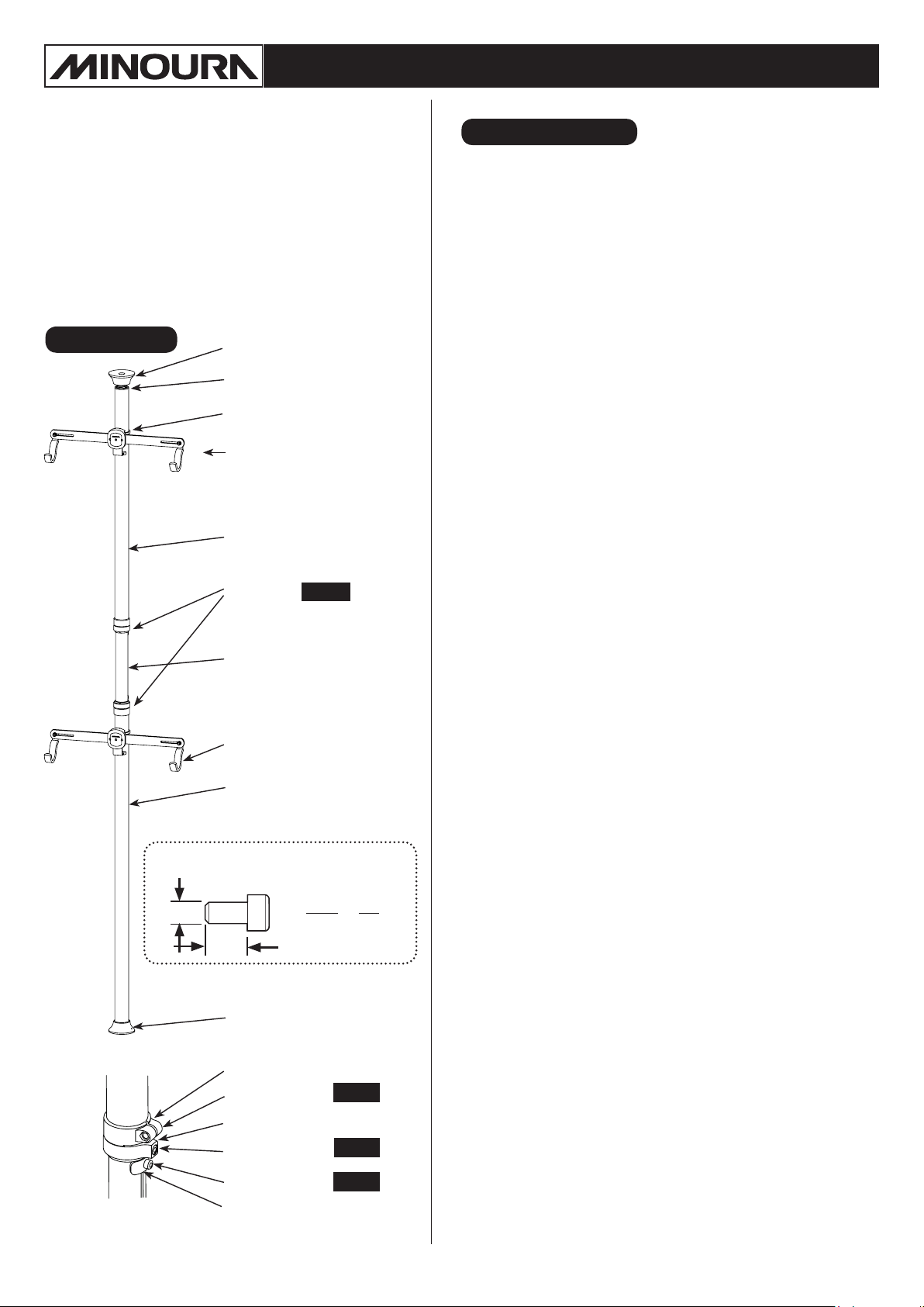
Part Name
Top Rubber Cup
(with spring inside)
Red Caution Indicator
Clamp
Bike Cradle
}
Upper Pillar
(45mm diameter)
Pillar Joint
8 N.m
Important Notes
• Use the supplied plastic tie to hold the pillar to the ceiling
or the wall to avoid the stand from toppling over if the pillar
length was shortened if there was an issue with the locking
bolt.
Minoura is not responsible for damage caused by misuse or
improper installation.
• For standard 2-wheel bike only. Not for use with tandems or
long wheel-base bicycles.
• Each bike cradle is rated to hold up to 25 kgs.
If mounting heavy bikes, check the cradle bolts often to make
sure they have not come loose.
• Check to make sure the Pillar Joint has remained secure by
pulling down the Upper Pillar after tightening the Pillar Joint
Bolt and the Lock Plate Bolt.
If the pillar has moved after tightening, discontinue using and
contact your dealer or Minoura distributor in your country.
You may need to replace the metal ring of the Pillar Joint.
• The pillar is supported by the internal spring applying
pressure to the ceiling.
Make sure that the pillar comes in contact with a stud or
other reinforced area of the ceiling otherwise the spring
pressure may cause damage to the dry wall or ceiling.
[Pillar Joint]
Center Pillar
(40mm diameter)
Cradle Hook
Lower Pillar
(45mm diameter)
How To Read The Bolt Size
Example)
Diameter
Length
Bottom Rubber Cup
(without spring inside)
Pillar Joint
Cap Bolt M6x15
Metal Ring
Cap Bolt M6x20
M 6 x 30
Diameter
(Plastic)
Length
(Unit: mm)
8 N.m
8 N.m
• Adjust the pillar length correctly. If the red plastic appears
beneath the Upper Rubber Cup, it means the pillar is not
adjusted properly (too short).
• Do not install the pillar upside down.
NEVER use BikeTower horizontally. It is for vertical use
ONLY.
• The pillar must be completely vertical, and not at any angle.
Failure to do so will cause the stand to fall.
• The rubber cap material may leave a mark on some ceilings
or oors.
We recommend placing a small piece of fabric, paper or
wooden plate between the rubber cup and the ceiling.
Do not use a slippery material such as a Vinyl sheet.
• The coating on the cradle hook may leave a mark on your
bicycle frame.
We recommend wrapping a piece of bar tape on the hook
where it comes in contact with the frame.
• Depending on the bike size, you may have to change the
clamp position from the fatter Upper or Lower Pillar to the
narrower Center Pillar.
In this case, install the supplied gray plastic shim between
the clamp and the pillar.
•
The pillar is just a single pole so it's easy to turn. Do not place
any fragile items or sharp edge articles around the pillar.
Cap Bolt M6x15
Lock Plate
Recommended Tightening Torque = 8 N.m
8 N.m
• This product is subject to change without prior notice for
quality and safety improvements.
Page 2
!
How To Setup
Measurement→Temporarily Setting→Adjusting Length→Setting→Check→Fix
Required Tool :
5mm Hex Wrench
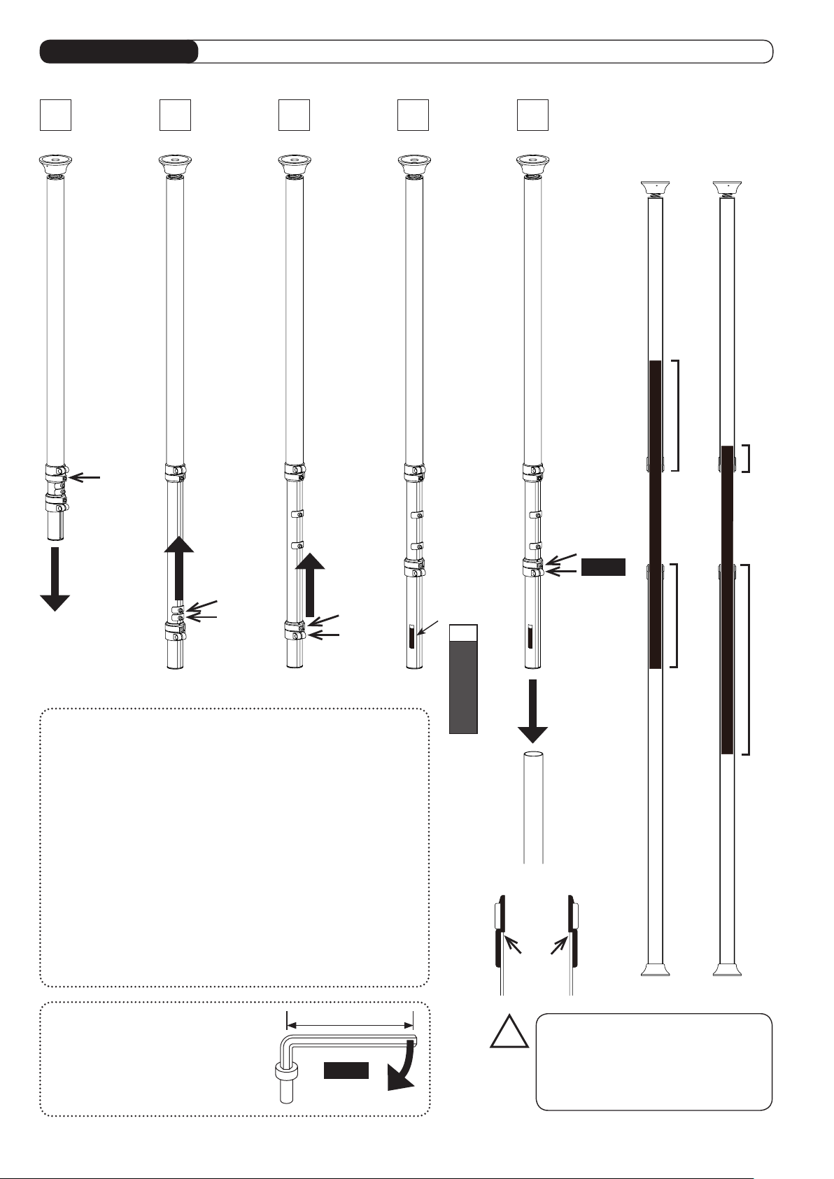
1
The Upper
and Lower
Pillars come
separated.
The Center
Pillar is
retracted inside
the Upper
Pillar.
2 3 4 5
Loosen two
M6x15 bolts
of the Lock
Plates, move
them to the
mid zone of
the Center
Pillar and
hold. (Fig. B)
Loosen both
M6x15 and
M6x20 bolts
to move the
lower Pillar
Joint upward.
(Fig. C)
Loosen the
M6x20 bolt of
the Metal Ring
on the upper
Pillar Joint
to extract the
Center Pillar.
Loosen
(Fig. A)
Extract
After extracting,
Move
Move
Loosen
tighten the bolts
temporarily.
(Fig. A)
(Fig. B)
Loosen
(Fig. C) (Fig. D)
About Center Pillar Insertion Depth
The BikeTower25D is constructed with two fatter pillars and single
narrower pillar combination.
The center pillar must be inserted into the upper or lower pillar at
least in the depth until the MAX decal becomes invisible. In this
condition, the pillar will have enough strength to support the load.
We strongly recommend you to insert the center pillar into both
the upper and lower pillars in the same length that would provide
maximum stability.
If the center pillar is not inserted evenly into the upper and lower
pillars, the balance of the stand will be off and could compromise
the overall stability of the stand.
Please be sure
the MAX
decal is put on
both top and
bottom end
of the Center
Pillar.
This tells you
need to insert
the Center
Pillar into the
Upper or the
Lower Pillar
in the depth
at least this
red indicator
becomes
invisible for
your safety.
(Fig. D)
MAX Decal
M
A
X
MAX
Insert
Insert the
Center Pillar
into the Lower
Pillar. (Fig. E)
Make sure the
top end of the
Lower Pillar
comes until
the end of the
Pillar Joint
plastic sleeve.
(Fig. F)
Tighten both
M6x15 and
M6x20 bolts on
the lower Pillar
Joint with the
tightening
torque 8 N.m to
fix the position.
M
A
X
The total
pillar length
adjustment will
be done on the
Upper Pillar
side only.
So leave the
upper Pillar
Joint as it is
temporarily
tightened.
(Fig. E)
Tighten
8 N.m
○
Same
length
is the
best
×
Not
good
For your reference, if your room's ceiling height is 2.4 meters (7.9'),
you should insert the center pillar in the depth of 25 centimeters (10").
It will give you the proper insertion ratio.
Calculation Of Tightening Torque
If the hex wrench length is 75mm,
pull the wrench tip with the power
of 107N (11 kgf) to expect 8 N.m
tightening torque.
75 mm
8 N.m
Pull with 107N power
(Fig. G)
(Fig. F)
The Lower Pillar must be fully inserted
into the Pillar Joint.
If some clearance remains, the pillar
may be too short and could fall down,
causing a serious accident.
- 2 -
Page 3
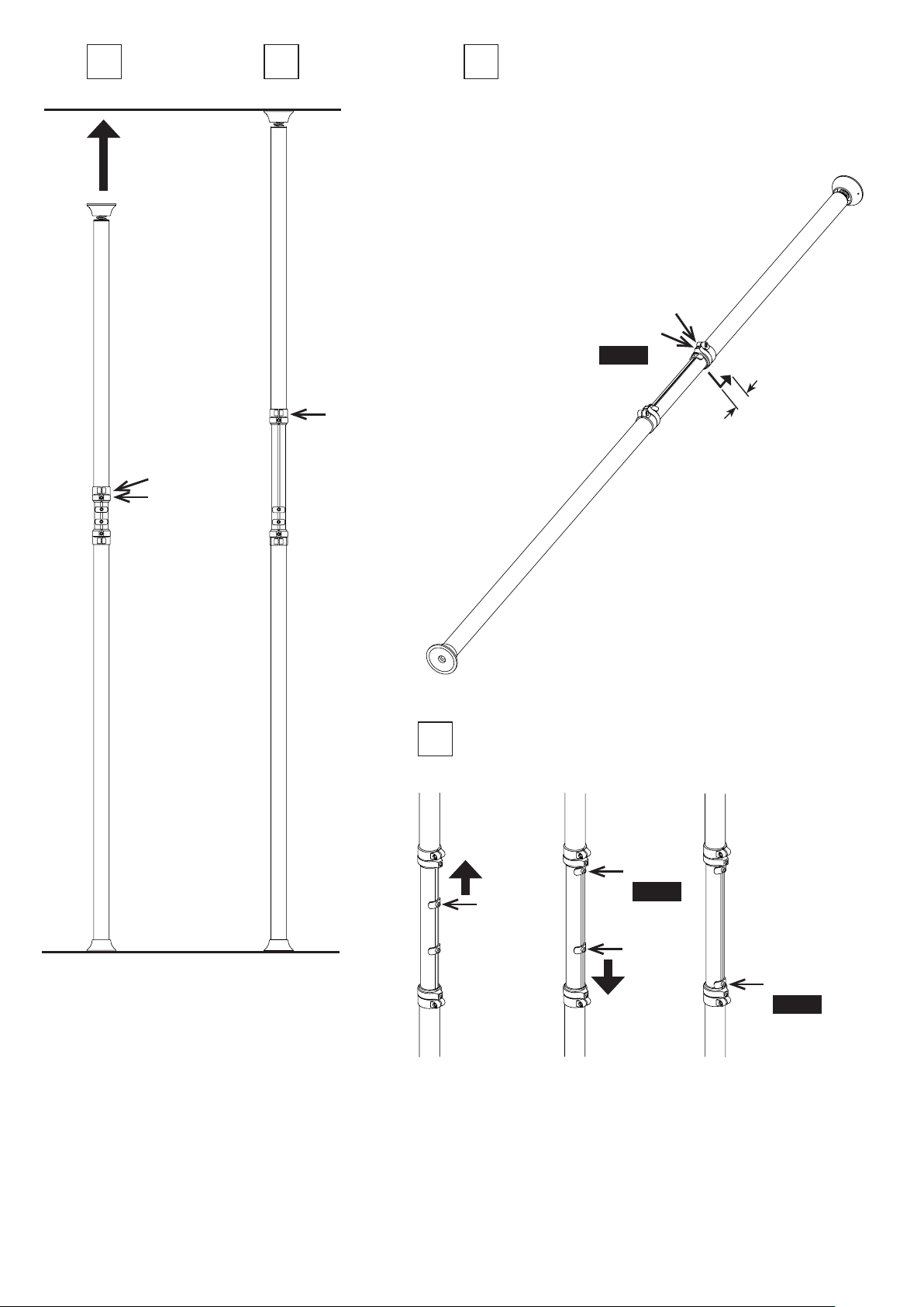
6 7
Extend
Lay the temporarily
adjusted pillar down
on the floor.
Then, lift up the
pillar and loosen the
upper Pillar Joint,
and extend the Upper
Pillar toward the
ceiling.
(Fig. H)
When the Top
Rubber Cup
reaches the ceiling,
stop extending
the pillar and
temporarily tighten
the upper bolt to
keep this pillar
length.
Temporarily
Tighten
8
Adjust the pillar length to the final size. (Fig. J)
①
Loosen the bolt on the upper Pillar Joint,
②
Extend the Upper Pillar
③
Tighten both bolts on the upper Pillar Joint firmly
at
8 N.m
torque.
20mm more
This is the final pillar length that will fit your room
perfectly.
Loosen
①
Tighten
③
8 N.m
,
②
Extend
20mm more
Loosen
Loosen
You don't need
to compress the
spring in the Top
Rubber Cup yet.
Just touching the
ceiling is OK for
n o w.
This is the first
pillar length that
fits to your actual
room height.
You will adjust the
pillar to the final
size.
(Fig. J )
Set the Lock Plates so the Center pillar is in the proper position
9
even if the bolts become accidentally loose.
Move
Loosen
Tighten
8 N.m
(Fig. H) (Fig. I )
(Fig. K) (Fig. L)
Loosen the bolt on
the upper Lock Plate
and move upward
until it touches the
Upper Pillar.
- 3 -
Loosen
Move
Tighten the bolt
firmly at 8 N.m
torque to fix it.
Next, loosen the
bolt on the lower
Lock Plate and
move downward
until it touches the
Lower Pillar.
Tighten
8 N.m
(Fig. M)
Tighten the bolt
firmly at 8 N.m
torque to fix it.
Now the pillar
length adjustment
is completed.
Page 4

10 11 12
Push Up
Completed
Hold the pillar with
both hands and
attach to the ceiling.
(Fig. N)
Make sure the area
you chose is the
reinforced by the
beam inside.
Push the pillar
strongly toward
the ceiling to
compress the
spring in the Top
Rubber Cup.
(Fig. O)
While compressing
the spring, scoot the
pillar until it stands
vertical. (Fig. P)
After setting up,
check if all bolts are
firmly tightend by
pulling down the
Upper Pillar by using
your own weight.
Pull down
Upper Pillar
to test
13
Scoot
(Fig. N)
(Fig. O) (Fig. P)
To prevent the possibility of the bikes falling down, Minoura strongly
recommends you to use the supplied plastic tie to support the pillar.
Wind the plastic tie around the pillar (just beneath the Top Rubber
Cup), squeeze the tie, and keep the end on the ceiling or the wall with
the supplied screw where a beam is located inside for reinforcement.
Or you can fix the Top Rubber Cup on the ceiling directly by screwing
at the dimple on the cup. (Fig. R)
Make sure you screw into a support beam.
- 4 -
Tapping Screw
M3.5x16 or 25
(Use the one
which reaches
the inside beam)
(Fig. Q)
Dimple
for direct
screwing
(Fig. R)
Page 5

!
!
!
!
Important Notes
Be sure to perform the pillar test for your own safety. Minoura is not responsible for any
damage that might occur from not performing this test.
If the pillar has been shortened, it means the bolt on the pillar joint or the lock plate has not
been tightend rmly enough. If loosened, tighten at 8 N.m torque after adjusting the pillar
length correctly.
It is your responsibility to regularly check the red indicator beneath the top rubber cup.
Set up the pillar perfectly vertical.
If the pillar is slanted, it may fall down when a load is applied.
Use the supplied plastic tie.
Minoura will not be responsible for any problem if you miss it.
If you cannot use the tie due to the ceiling or wall material, it is your own responsibility to
use BikeTower alone.
Make sure you screw to the reinforcement beam. The screw may come off easily if you
screw to just the panel.
Regularly check if the red indicator becomes visible just beneath
the top rubber cup. (Fig. S)
If you can see the red indicator, it means the pillar is too short and
may be unstable.
Remove the pillar from the ceiling, extend it until the indicator
becomes hidden, then install the pillar again.
If the pillar continues to become shorter even if you tighten the
bolts rmly, the pillar joint may be deformed. Minoura will replace
the joint parts.
Immediately remove your bikes from the stand and contact your
dealer or the distributor from which you purchased the stand.
Do not continue using BikeTower while the pillar joint has been
loosened.
(Fig. S)
Red Indicator
- 5 -
Page 6

Schematics of Bike Cradle
!
!
!
Arm Bar
Clamping Bolt
Pivot Pin
Fixing Bolt
Base Plate
Hook Fixing Bolt
with Spring & Flat
Washers
Hook
(assembling
required)
Angle Adjusting
Cradle Cap
(assembling required)
Clamp Connecting Bolt
(Center)
(assembling required)
How To Install Bike Cradle
The clamp body has been pre-installed on the pillar. You will install the bike cradle to the clamp.
The hook and the cradle cap are separated. You will install them on the cradle later.
Install the rectangle projection part of the Clamp Body into the rectangle hole on the Base Plate. (Fig. T)
1
Required Tool: 5mm Hex Wrench
Bolt
(Left & Right)
Pad
Pivot Pin
Clamp Body
(pre-installed on
the pillar)
(Fig. T)
Be sure to put the rectangle projection evenly and into the hole level. If it is not completely
level, the clamp may be damaged and it will become difcult to screw the Clamp Connecting
Bolt into the thread hold on the Clamp Body.
The clamp body is made of soft light alloy material and this part cannot be repaired. You
must replace it at your own expense if damaged.
A thread has a unique physical mechanism that you can screw the bolt in the slightly slanted
angle.
The bolt will stop turning after 2-3 rotations so do not force the bolt any further or you could
cause damage to the stand.
You must conrm rst that you can rotate the bolt at least 3 rotations smoothly without using
any tool. After that, you can use tool for tightening more.
Screw the M6x20 cap bolt in the parts pack to the Clamp body through the center hole on the Arm Bar. Tighten the bolt
2
firmly by 5mm hex wrench.
Install the Hooks to both ends of the Arm Bar.
3
The hook is position and angle adjustable in order to fit your bike frame size and design as perfectly as possible.
Install the Cradle Cap to the Base Plate.
4
You should attach the cap bottom first, then push the top for better installation. Failure to do so may cause the cap
breakage problem.
After installation of the Cradle Cap, you will tighten or loosen the bolts through the hole on
the cap.
When you need to remove the cradle from the clamp body, you should not keep pushing
the cradle forward. The cap will lift up naturally while loosening the bolt. Otherwise, the bolt
head may push and remove the cradle cap.
- 6 -
Page 7

!
!
How To Reinstall The Clamp
!
You may need to remove and change the installation position of the bike cradle from the fatter Upper Pillar to the narrower
Center Pillar depending on the bike size or the bike layout. To do so, follow the steps below.
If you just change the installation position among the same pillar, just loosen the clamp, no need to remove.
Required Tool : 5mm Hex Wrench
You can change the clamp position while the
1
cradle is still on attached to the clamp.
Loosen and remove the Pivot Pin Fixing Bolt, the
Clamping Bolt, and the Pivot Pin.
Now you can open the clamp arms to remove it
from the pillar.
Wrap the clamp arm around the pillar. (Fig. U)
2
The clamp has single arm side and twin arm side.
This instruction tells as you set the single arm on the
right hand side, but the clamp is universal with no
specific direction.
(Bike Cradle is deleted in this section for explanation.)
Upper or Lower
Pillar
(Larger diameter)
(Fig. U) (Fig. V)
Install Shim
Center
Pillar
(Smaller
diameter)
Turn the Pivot Pin to align the thread hole to the
4
side hole on the Clamp Band.
Screw the Clamping Bolt into the Pivot Pin.
(see Fig. X)
Tighten
8 N.m
Tighten the Clamping Bolt first, then tighten the
5
Pivot Pin Fixing Bolt later firmly (
8 N.m
To Adjust On The Same Pillar
If you need to adjust the clamp position along
6
the same pillar, simply loosen (do not remove)
the Pivot Pin Fixing Bolt and the Clamping Bolt
slightly.
(Fig. X)
).
When installing the clamp band to
the smaller diameter Center Pillar,
you must put the gray Plastic Shim
between the clamp band and the
pillar as a spacer.
Make sure the dual ribs are located
on the single arm side. (see Fig. V)
Put the Pivot Pin through all 3 holes on the clamp
3
band from bottom side, and screw the Pivot-Pin
Fixing Bolt with a flat washer temporarily.
(see Fig. W)
Do not install the Pivot
Pin from the top.
You will not be able to
use the hex wrench.
Do not tighten the Pivot Pin
Fixing Bolt firmly yet.
If you tighten too much, the
next step will become difficult.
(Fig. W)
- 7 -
When sliding the clamp on the pillar,
loosen the screws and open the
arms as widely as possible in order
to avoid scratching the pillar.
Do not twist the clamp along the
pillar, but slide it straight up or down
gently.
Warranty Period
Minoura offers
from the date of your purchase.
Any natural wear and the problems caused by miuse
or unapproved modification will not be covered by this
program.
For more details, read the enclosed
Warranty Policy
Also please regularly check our Minoura web site for the
latest information.
1-year limited warranty
card in the kit.
to this product
Minorua Limited
Page 8

Adjusting Cradle Width & Angle How To Mount Bike
!
!
!
The bike cradle's hook span and arm bar angle are
adjustable in order to fit to various types of bike frame in
order to hold them as horizontal and stable as possible.
How To Slide Cradle Hook
To mount a bike on the cradle, place the top-tube on the
hooks.
Usually, you hold the top-tube by both hooks, but if the
bike frame design is specially sloping, you should set the
rear side hook under the seat-tube to keep the bike from
sliding off. (see Fig. AA)
Setting the front end to higher than the rear
of the bike may cause the wheel to turn
and possibly chip or damage the frame.
Minoura recommends keeping the front end
lower if possible or using a strap to secure
the front wheel to the frame or stand to
avoid such accidents.
The hook material may stain on your bike
frame.
We recommend placing a piece of bartape between the hook and the frame or
wrapping the hook with bandage in order
to avoid contact with each piece.
(Fig. Y)
Take the bike off the cradle.
Loosen the bolt and slide the hook to adjust the position.
You should set the hooks symmetrically to maintain
maximum bike stability.
Do NOT try to adjust the hook while the
bike is in the cradle. Doing so may cause
the bike to fall off the stand.
How To Adjust Cradle Angle
Special style to hold the bike
(image: BikeTower20)
(Fig. AA)
Contact
MINOURA JAPAN
1197-1 Godo, Anpachi, Gifu 503-2305 Japan
Fax : +81-584-27-7505
URL: www.minoura.jp
Mail : minoura@minoura.jp
Insert the 5mm hex wrench into both
the right side and the left side holes on
the Cradle Cap, and loosen the inside
bolts slightly (do not remove). (Fig. Z)
Now the cradle is ready to adjust the angle.
After adjustment, tighten both bolts firmly to fix the
position.
Made in Japan
(Fig. Z)
- 8 -
 Loading...