

Page 1
BIKE TOWER Instructions Manual
Thank you for purchasing Minoura BIKE TOWER display stand.
Thsi is the display stand which can hold 2 or more bikes (limit 4 bikes) on its cradles at two different
heights and in front and behind the pole.
The main pole is adjustable from 1.6 meter (5’ 3”) to 3.1 meter (10’ 2”) between the floor and the
ceiling of your room.
Most parts are made of light alloy so the completed weight of the Bike Tower is only 3 kgs, therefore
your can move it anywhere you want easily and its simple design can fit everywhere.
IMPORTANT NOTES
• Please read this instructions manual carefully before use.
• Bike Tower is the display stand for ordinary 2-wheel bicycles only. Do NOT use it for any other
purpose, for example, for displaying heaviy electric bikes or tandem bikes.
• Bike Tower is installed between the floor and ceiling using a strong spring and the tension this
provides. Bike Tower MUST be installed firmly on a a solid floor and ceiling using a supporting
beam or load bearing area of the ceiling. Failure to do so may cause damage to your ceiling,
bikes, Bike Tower, and may cause personal injury.
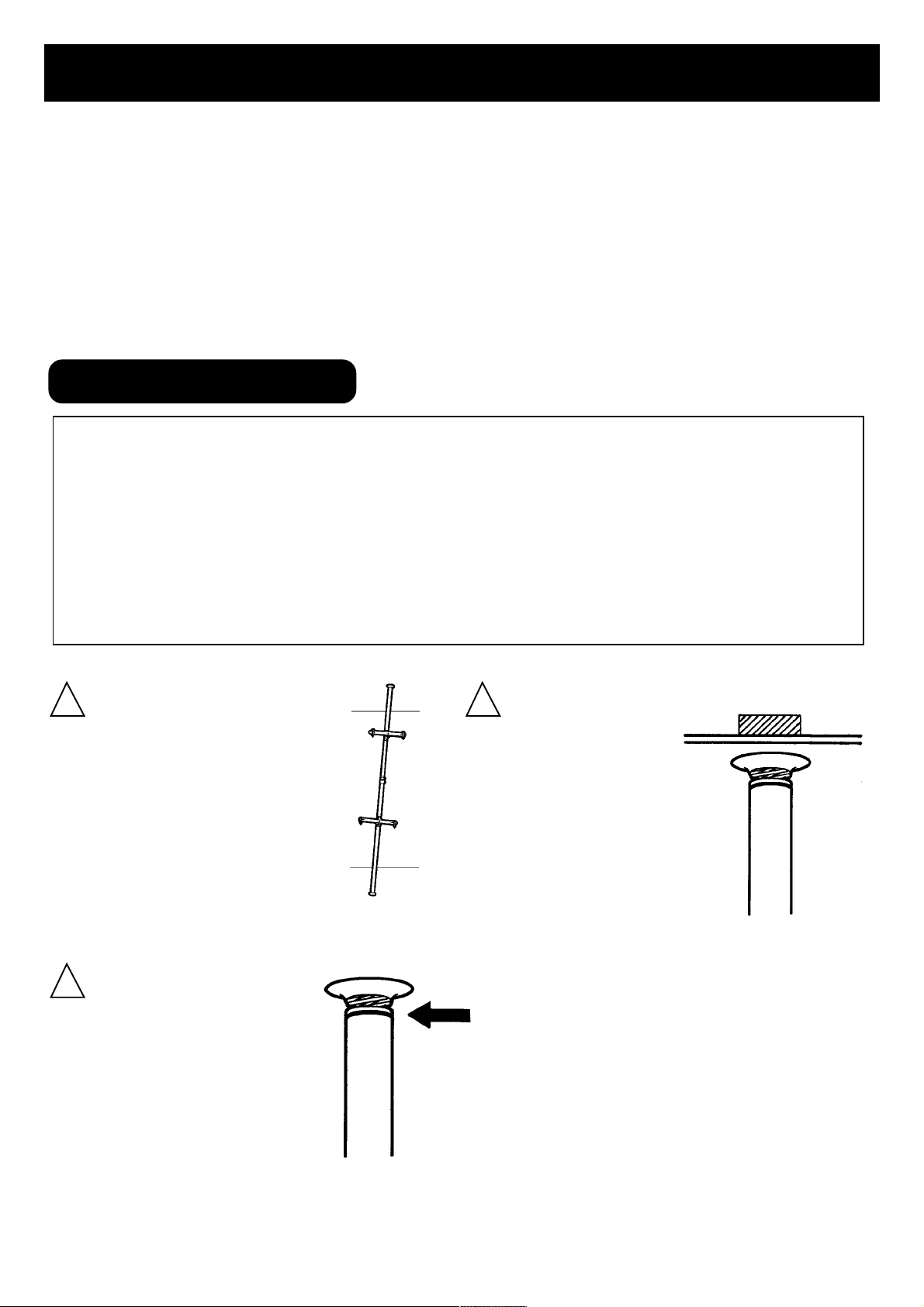
! !
Set the Bike Tower up vertically
from floor to ceiling. Make sure
the Bike Tower is not slanted.
Slanted installation may cause
the Bike Tower to fall down,
causing damage and/or injury.
X
Set Bike Tower firmly
against a supporting
beam or load bearing
area of the ceiling. Failure
to do so will cause damage to your ceiling.
ceiling supporting beam
!
When setting the main
telescoping pole, make
sure to extend it until the
red warning sign no longer
shows. The warning sign is
located just below the
upper rubber cup.
Red Warning Sign
- 1 -
Page 2
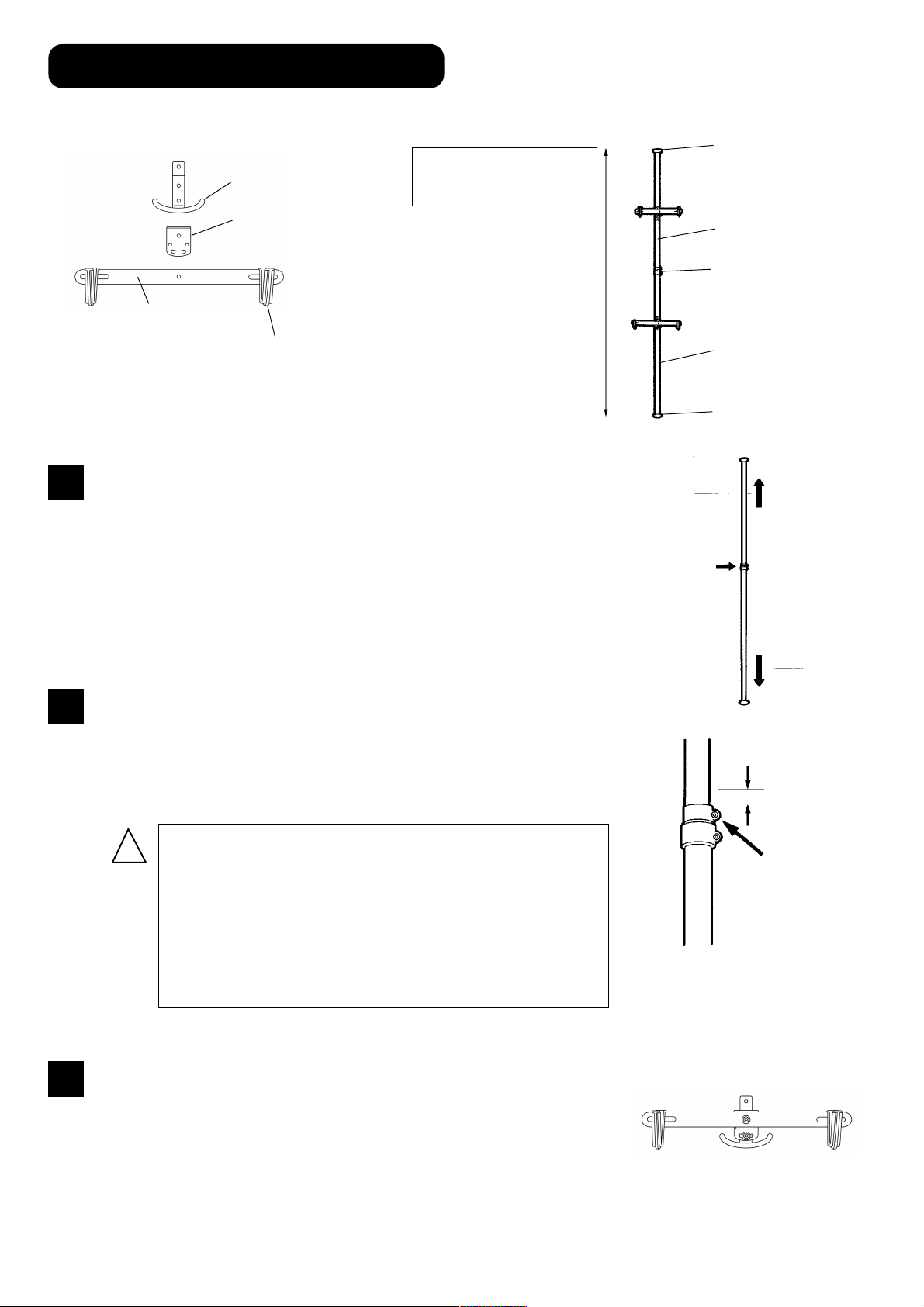
HOW TO SETUP BIKE TOWER
We explain the name of each part as below;
Lower Support
Required tool : 5mm hex wrench (included)
Upper Rubber Cup
Height range:
1.6m (5’3”) - 3.1m (10’2”)
1
Angle Adjust Plate
(projection is foreside)
Alloy Stay
Frame Hook
Loosen the upper bolt on the Pole Joint then extend the main pole.
After you fit the main pole to the ceiling, tighten the bolt slightly.
(see Fig. A)
Tighten temporaly
Upper Pole
Pole Joint
Lower Pole
Bottom Rubber Cup
2
3
Remove the main pole, making sure the pole length is not
changed.
Extend the main pole 20mm more, then tighten the upper
bolt on the Pole Joint firmly to set the pole length. (see Fig. B)
!
A loose the bolt on the pole joint may cause the
pole to slide down when a bicycle is in the cradle.
Overtightening the bolt on the pole joint may cause
the plastic pole joint to break.
Make sure the pole joint bolt is snug and that the
joint will not move.
Assemble the cradles.
Place the Angle Adjust Plate onto the Lower Support,
then put the Alloy Stay on it. Fix three parts with the
(Fig. A)
+20mm
loosen and
tighten
(Fig. B)
supplied M6x20 bolt in the upper hole. (see Fig. C)
Screw the supplied M6x15 bolt in the lower hole, but
you don’t need to tighten it so firmly at this time.
- 2 -
(Fig. C)
Page 3

4
The distance between the plastic frame hooks can be adjusted to fit different sized bicycles.
To do so, loosen the rear nut and adjust the position of
the hook. After adjusted to the required position, retighten the nut firmly. (see Fig. D)
(Fig. D)
5
Now, disassemble the supplied stainless band device by
removing the bolt.
Wind the stainless band around the pole, and insert the end
of the band into the gap between another end and the rectangle nut.
Holding it in place, put the plastic bracket and assembled
cradle together, then tighten them down with the bolt you
removed earlier. (Fig. E)
!
!
The stainless band must ONLY be used on the upper side
of the cradle. DO NOT use it on the bottom portion of the
cradle.
Tighten the bolt on the stainless band firmly. Failure to do so
may cause the bicycle to slip down the pole.
(Fig. E)
stainless band
just putting onto
the pole
(Fig. F)
1
6
Set the Bike Tower between the ceiling and the floor.
First, put the upper rubber cup against the ceiling and push
the pole up to contract and shorten the inside spring.
Next, line up the bottom rubber cup until the main pole is
vertical. Once you line up the top and bottom, pull down the
main pole softly. (see. Fig. G)
!
!
If the red warning sign is visible below the rubber cup even
after following the above instructions, the pole extension is too
short and may cause the bikes to fall over. Please start the
installation process over again to insure proper set up and that
the red warning label does not appear.
Make sure the Bike Tower is set up vertically with no slant.
Failure to do so may cause equipment or personal damage.
2
(Fig. G)
7
The cradle is adjustable in degrees. If you want to move
the cradle, loosend the lower bolt on the angle adjust
plate, change the angle until the displayed bike will be
horizontally as much as possible then tighten the bolt
again. (see Fig. H)
- 3 -
(Fig. H)
Page 4

HOW TO USE BIKE TOWER
Bike Tower can stand alone, but we recommend it is set-up next to a wall for increased safety.
Lift the bicycle and gently place the top tube
into the frame hooks.
If the bicycle does not have a standard frame
design, it should be supported by the top tube
and rear seatstay configuration. (see Fig. I)
OX
BIKE TOWER USE CHECK LIST
You must check the following points before use;
1. Check that there are no cracks in the main pole or plastic brackets.
2. Check that all fittings are securely fastened.
3. Check to make sure the main pole is not bent or developing any rust.
WHY MY NUT IS MISALIGNED?
(fig. I)
The inside nut of the stainless band clamp is not square, it is rectanle. You have to remove the stainless
band to wind up it around the pole for assembling. At this time, do NOT remove the nut from the band.
If you had removed the nut, make sure the nut direction that the longer side must be vertical. If you see
there is some space between the nut and stainless band, the direction is wrong.
FOR MORE INFORMATION
For parts or service outside of Japan or North America, please consult your local shop or our international distributor list (found on our web site) for a distributor in your country.
MINOURA JAPAN
1197-1 Godo, Anpachi, Gifu 503-2305 Japan
Phone +81-(0)584-27-3131 / Fax +81-(0)584-27-7505
Email : minoura@minoura.jp http://www.minoura.jp
MINOURA NORTH AMERICA (for North American residents only)
1996 East Avenue, Hayward, CA 94541-5454 U.S.A.
Fax 1-510-538-5899 / Email : MinouraUSA@ATTglobal.net
Made & Quality Controlled in Japan
Copyright 2002 Minoura Co.,Ltd. All rights reserved
- 4 -
 Loading...