

Page 1
Extra Bike Hanger Kit
Bike Cradle 4
instructions manual
(ver.1.1 2014/8)
CRADELE 4
49 44924 42220 2
We suggest wrapping
!
the hook with bar tape to
minimize discoloring of
lighter colored frames.
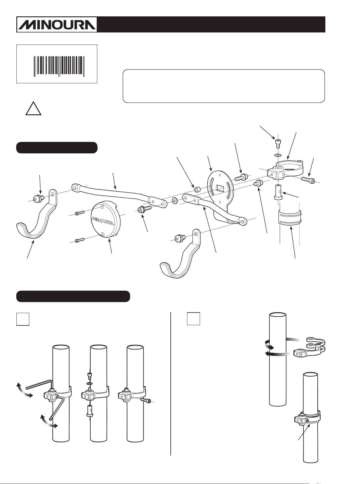
Schematics
Hook Fixing Screw
Bike Cradle 4's arm has dierent shape from Bike Cradle 3. It's the bent type
in order to enable to place the bike further from the pillar to avoid conicting
with the pedal.
<Applicable Tube Diameter: 38 – 45mm>
40mm = for BikeTower / BikePit upper pillar
45mm = for BikeTower / BikePit lower pillar, P-500 / 600 / 700 pillar
Left Side Arm (foreside)
Spacer Collar
(Left side only)
Left Arm Angle
Adjusting Screw
Main Bracket
Pivot-Pin
Fixing Screw
Clamp
Clamp
Tightening
Screw
Pivot-Pin
Hook
Cradle Cap
How To Install Cradle4
At first, remove the Pivot-Pin, Pivot-pin Fixing
1
Screw and Clamp Tightening Screw to open the
clamp (see Fig. A).
Arm Connecting
Screw
Required Tool: M5 Hex Wrench
2
Widely open the clamp then
wind arond the pillar.
Make sure the single fatter arm
is located on the right side, and
two narrower arms are located
on the left side (see Fig. B).
Opposite combination doesn't
work.
Right Arm
Angle Adjusting
Screw
Right Side Arm
(backside)
(not supplied)
Shim
(use if the pillar diameter is
smaller than 43mm)
(Fig. B)
(Fig. A)
- 3 -
If the pillar diameter is smaller
than 43mm, install the supplied
plastic Shim first, then wind the
clamp over the shim (see Fig. C).
Make sure you install the Shim
in correct direction. Dual rail
must fit to the single arm side.
Shim
(Fig. C)
Page 2
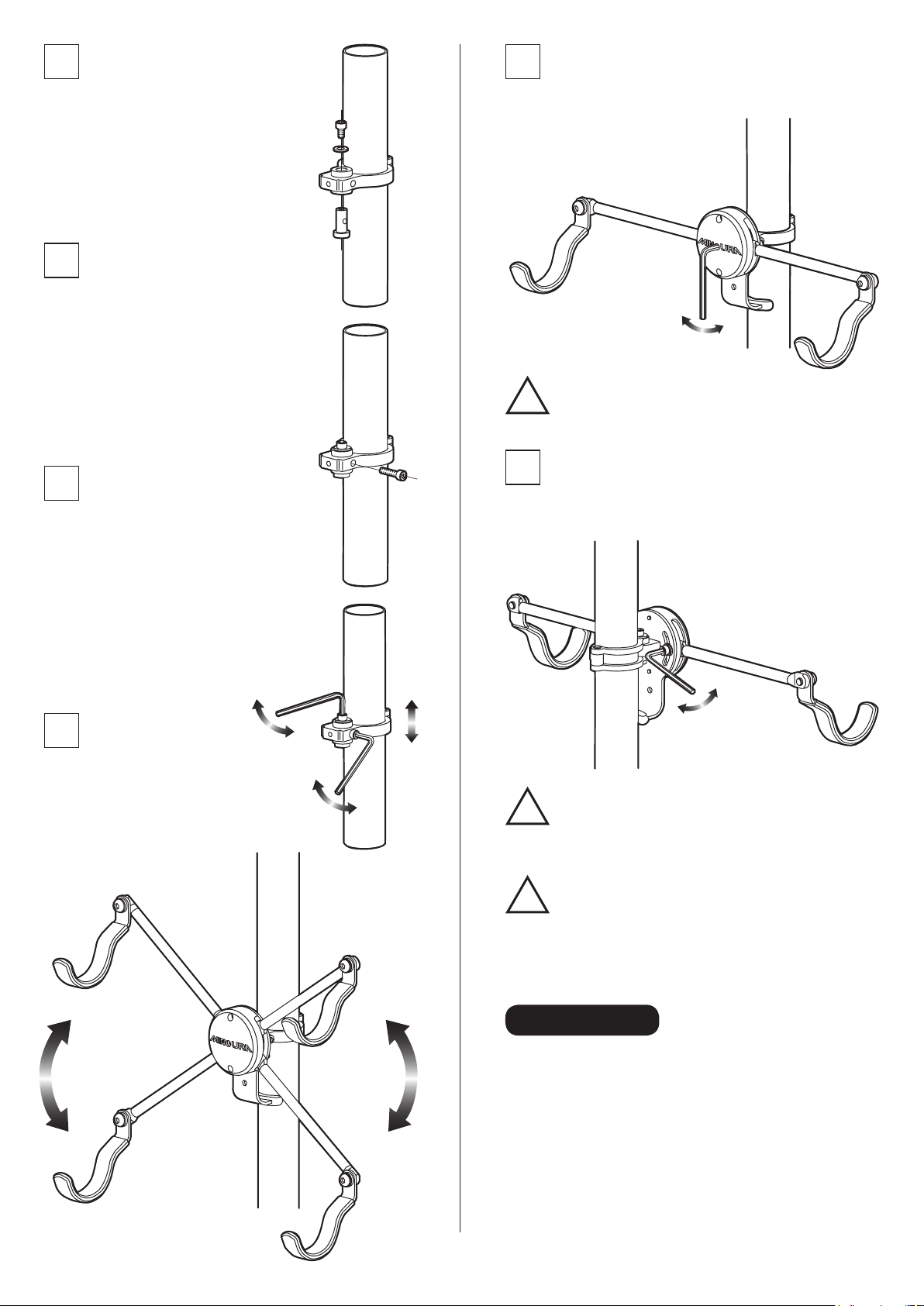
3
Insert the Pivot-Pin to the clamp from
bottom hole, and screw the Pivot-Pin
Fixing Screw with a washer to hold the
pin (see Fig. D).
You don't have to tighten the bolt
firmly yet.
To change the arm angle, insert an M5 hex
7
wrench into the center hole on the Cradle Cap
then loosen the Arm Connecting Screw.
(see Fig. H)
(Fig. H)
4
Rotate the Pivot-Pin to align the thread
hole on the pin and the side hole on
the clamp body, then screw the Clamp
Tightening Screw.
(see Fig. E).
You don't have to tighten the bolt firmly
yet.
(Fig. D)
5
After fixing the clamp height
and angle, tighten the Clamp
Tightening Screw first (see Fig. F).
(Tightening Torque: 3 N.m)
After that, tighten the Pivot-Pin
Fixing Screw to secruely hold the
clamp.
(Fig. E)
Do not remove the Arm Connecting Screw.
!
Just loosen.
Loosen the backside screw which holds the arm,
8
grab the arm and change the arm angle.
After changing the angle, tighten the screw firmly.
(see Fig. I)
6
Each arm is fully angle
adjustable in +/- 35 degrees in
order to fit various types and
sizes of bike frame (see Fig. G).
(Fig. F)
(Fig. G)
- 4 -
(Fig. I)
Do not set both hooks higher than level.
!
The hook which holds the main load must
be located lower than the clamp body.
Tighten every bolt rmly before loading the
!
bike. If the arm xing screws have been
loosened, they may come down due to the
bike weight and may drop the bike in the
worst case.
Contact
If you need help or have a question, please contact the shop first
where you originally purchased this product.
If you cannot get enough service or answer from them, you can
contact us directly.
MINOURA JAPAN
1197-1 Godo, Anpachi, Gifu 503-2305
Phone +81-584-27-3131 / Fax +81-584-27-7505
minoura@minoura.jp / www.minoura.jp
Made in Japan
 Loading...