


Option
Service Manual
EDH-5
C-403/C-404
FN-7/FN-115
Cover Inserter C
PK-3
ZK-2
TMG-2

Dual references may be used on the following:
Official Options name : Popular Options name
EDH-5 : RADF
C-403/C-404 : LT and LCT
FN-115 : FNS
FN-7 : FNS
Cover Inserte Cr : PI
PK-3 : PU
TMG-2 TU
ZK-2 : PZ
In-System Writer : ISW


EDH-5
RADF

RADF

CONTENTS
EDH-5
SAFETY AND IMPORTANT WARNING ITEMS
Refer to the Di850 service manual on page.......... S-1
1. OUTLINE
PRODUCT SPECIFICATIONS..................................1-1
CENTER CROSS-SECTIONAL DRAWING..............1-2
DRIVE SYSTEM DIAGRAM ......................................1-3
ORIGINAL CONVEYANCE PROCESS.....................1-4
[1] Single side original copy mode (large) .......1-5
[2] Single side original copy mode (small).......1-6
[3] Double side original copy mode (large)......1-7
[4] Double side original copy mode (small) .....1-8
[5] Mixed original copy mode...........................1-9
2. UNIT EXPLANATION
EXTERNAL SECTION...............................................2-1
[1] Composition ...............................................2-1
[2] Mechanisms ...............................................2-1
ORIGINAL FEED/CONVEYANCE/EXIT SECTION...2-2
[1] Composition ...............................................2-2
[2] Mechanisms ...............................................2-2
[3] Original Fe ed/Conveyance/Scan Control ...2-4
[4] Original Reversal and Conveyance
Control........................................................2-7
[5] Original Exit Control ...................................2-9
[6] Original Size Detection Control ................2-11
RADF

RADF

1
OUTLINE
RADF

RADF
PRODUCT SPECIFICATIONS
EDH-5
[1] Type
Type
Sheet-through type reversible DF
[2] Functions
Original size:
• Metric area
A3 / B4 / A4 / A4R / B5 / B5R / A5 / A5R
11 x 17 / 8.5 x 14 / F4
• Inch area
11 x 17 / 8.5 x 14 / 8.5 x 11 / 8.5 x 11R /
5.5 x 8.5 / 5.5 x 8.5R
A3 / B4 / A4 / B5 / B5R
• All sizes are detected automatically.
• Mixing of original sizes possible.
Original type:
Plain original
50 to 200 g/m
paper.
Special original
Original feed and conveyance ability may be
inferior to those of 50 to 130 g/m
lbs high quality original.
Only SDF mode single-sided passage allowed
for 131 to 200 g/m2 or 35 to 45 lbs thick original.
The following types of original cannot be used:
• OHP film
• Blueprint masters
• Label original
•Offset masters
• Bonded originals
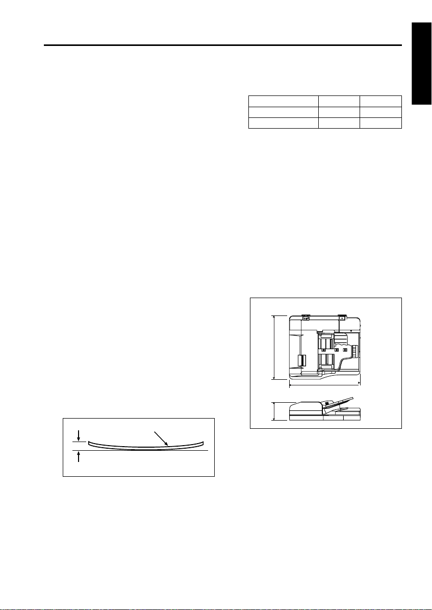
Original curling:
10 mm maximum
2
or 14 to 45 lbs high quality
Original
2
or 14 to 35
Original read speed (copies per minute,
600dpi):
Mode Original size Feed speed
Single sided original A4/8.5x11 85
Double sided original A4/8.5x11 58
Original feed layout:
Face-up placement, centered, U-turn feed/
straight eject (large size/small size independent eject), reversal section placed at ejection
side.
Original image read position:
At the slit glass section
[3] Machine Data
Power source:
DC24 V / 5 V (supplied from the main unit)
Max. power consumption:
Less than 180 VA
Weigh t:
Approx. 21.5 kg
Machine dimensions:
570
650
170
RADF
Unit: mm
Amount of curl
Maximum number of stacked originals:
100 sheets maximum (80 g/m
2
or 22 lbs)
[4] Maintenance
Maintenance : Same as the main body
Service life : Same as the main body
[5] Operating Environment
Temperature:
10 to 30 °C (50 to 86 °F)
Humidity:
10 to 80 % RH
Note: The information herein may be subject to
change for improvement without notice.
1-1
EDH-5
CENTER CROSS-SECTIONAL DRAWING
RADF
3
1
2
4
5
6
7
8
17
18
1. Original conveyance roller
2. Registration roller
3. Double feed prevention roller
4. Separation roller
5. Original feed roller
6. Original feed tray
7. Original exit tray (for large-size original)
8. Original exit section (for small-size original)
9. Original exit roller 2
15
14
16
13
12
11
10. Original exit reversal roller
11. Original exit gate
12. Reversal conveyance roller 2
13. Reversal conveyance roller 1
14. Reversal roller
15. Original exit roller 1
16. Flapper
17. Read position
18. Slit glass
10
9
1-2
DRIVE SYSTEM DIAGRAM
2
FRONT
1
EDH-5
RADF
3
4
10
FRONT
5
6
7
8
11
20
19
18
9
12
14
13
15
16
17
1. Separation roller
2. Registration roller
3. Flapper drive SD (SD 301)
4. Original conveyance roller
5. Original conveyance motor (M301)
6. Flapper
7. Original feed motor (M302)
8. SDF switching SD (SD304)
9. Tray up/down drive motor (M303)
10. Original feed roller
11. Original exit gate SD (SD303)
12. Original exit gate
13. Pressure roller release SD (SD302)
14. Reversal conveyance roller
15. Original exit roller 1
16. Reversal roller
17. Original exit motor 1 (M304)
18. Original exit motor 2 (M305)
19. Original exit reversal roller
20. Original exit roller 2
1-3
EDH-5
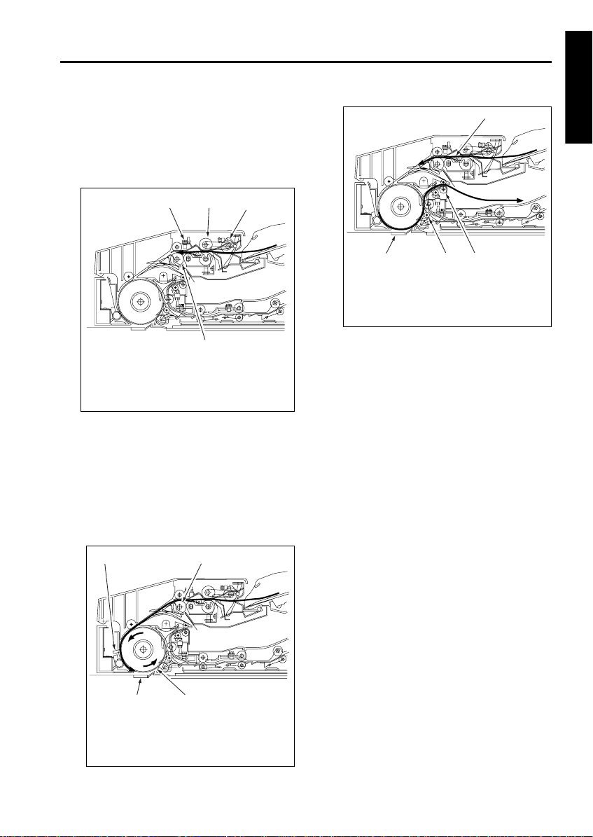
ORIGINAL CONVEYANCE PROCESS
RADF
The RADF consists of a original feed section, conveyance section, reversal section, original exit reversal section, original exit tray (large), and original exit tray (small).
Original feed section
Original exit tray
Conveyance section
Reversal section
Slit glass (Read section)
The original placed faced up on the original feed
tray is fed from the topmost original. The fed original is not conveyed to the original glass. Instead,
it is read when it passes the slit glass placed in
the conveyance path.
The RADF operation consists of (a) single side
original copy mode, (b) double side original copy
mode, (c) mixed original copy mode and Z fold
mode. Each has a different conveyance path.
The conveyance path also depends on the original size.
Original exit reversal section
Original exit tray (small)
1-4
EDH-5
)
)
[1] Single side original copy mode (latge)
(single side to single side copy, single side to
double side copy)
The original set in the original feed tray is fed by
the original feed roller and separation roller until
PS306 (original registration detection) turns on.
1
1. Original registration detection PS (PS306
2. Separation roller
3. Original feed roller
4. Registration roller
When PS306 turns on, the registration roller prefeeds the original and original is rapidly conveyed
to the conveyance roller. The speed of the conveyance roller changes to scan speed at predefined interval after PS306 turns ON and feeds
the original over the slit glass.
At this point, if the next original is present, it is
pre-fed as soon as PS306 detects its leading
edge.
2
3
4
1
3
4
1. Next original
2. Original exit roller 1
3. Flapper
4. Slit glass
The original is read when it passes over the slit
glass. The original that has been read is conveyed along the circumference of the conveyance roller by the opening of the flapper, goes
through original exit roller 1, and is exited to the
original exit tray (large).
2
RADF
1
4
1. Original conveyance detection PS (PS308
2. Registration roller
3. Original conveyance roller
4. Slit glass
2
3
1-5
EDH-5
RADF
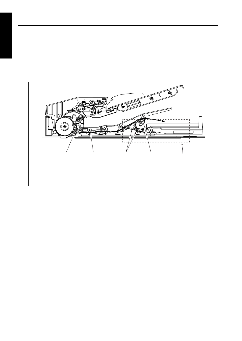
[2] Single side original copy mode (small)
(single side to single side copy, single side to double side copy)
The original feed and conveyance actions up to scanning are performed in the same manner as for single
side original copy mode (large). The original that has been scanned is fed to the original reversal unit by the
reversal roller because the flapper is closed and the paper exit path is blocked. The original fed to the reversal
unit passes through the original exit roller 2 and is exited to the original exit tray (small) since the original exit
gate is closed.
4
1. Original exit roller 2
2. Original exit gate
3
2
3. Reversal roller
4. Flapper
1
Original reversal section
1-6
EDH-5
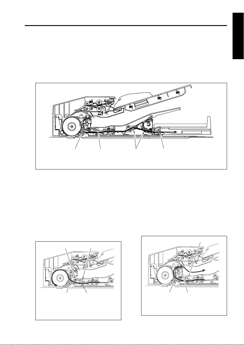
[3] Double side original copy mode (large)
(double side to single side copy, double side to double side copy)
The original conveyance action up to the start of scanning of the front side of the first double side original is
the same as for single side original copy mode (large). The original that has been scanned and read on the
front side is fed by the reversal roller to the reversal unit since the flapper is closed and the original exit path
is blocked. The original fed to the reversal unit does not fit in the reversal unit so the original exit gate opens
to feed it to the original exit reversal section.
4
1. Original exit reversal roller
2. Original exit gate
When the original reversal detection PS (PS309)
detects the trailing edge of the original and turns
off, the reversal roller changes direction and
feeds the original in the reversal section to the
conveyance roller. Since the original is passed
over the surface of the flapper, it is sent to the
conveyance roller with sides reversed. The original reaching the conveyance roller does not exit
the reversal roller so the pressure roller is
released. The conveyance roller feeds this original over the slit glass for scanning.
1
3
2
2
3. Reversal roller
4. Flapper
The original that has completed scanning of the
back side is fed inside the reversal unit once
again since the flapper is closed. When PS309
detects the trailing edge of the original and turns
off, the reversal roller changes direction and
feeds the original in the reversal unit to the conveyance roller. Since the flapper is now opened,
the original is fed along the flapper, passes
through original exit roller 1, and is exited to the
original exit tray (large).
1
1
RADF
4
1. Original reversal detection PS (PS309)
2. Reversal roller
3. Pressure roller
4. Flapper
3
1-7
3
1. Reversal roller
2. Original exit roller 1
3. Flapper
2
EDH-5
RADF
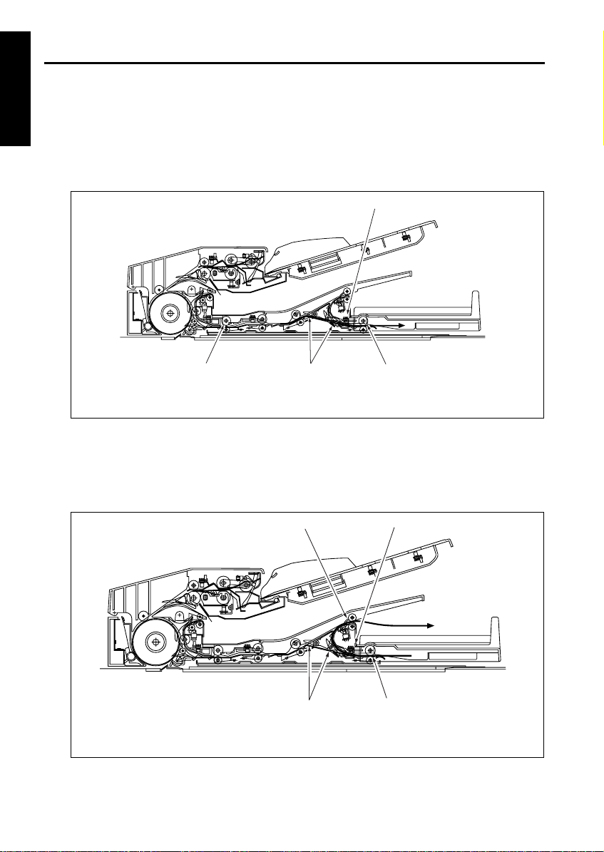
[4] Double side original copy mode (small)
(double side to single side copy, double side to double side copy)
The original conveyance action up to the start of scanning of the back side is the same as double side original
copy mode (large). The original that has been scanned and read on the back side is fed by the reversal roller
to the reversal section since the flapper is closed and the original exit path is blocked. Then the original exit
gate opens and the original is fed to the original exit reversal section.
1
4
1. Original exit reverse detection PS (PS313)
2. Original exit reversal roller
When PS313 (original exit reverse detection) detects the trailing edge of the original and turns off, the original
exit reversal roller changes direction and feeds the original to the original exit gate. Since the original exit
gate is closed, the original passes over the original exit gate and is exited from the original exit roller 2 to the
original exit section (small) with sides reversed.
1. Original exit roller 2
2. Original exit reverse detection PS (PS313)
3
3. Original exit gate
4. Reversal roller
1
4
3. Original exit reversal roller
4. Original exit gate
2
3
2
1-8

EDH-5
[5] Mixed original copy mode
The mixed original copy mode supports both the
same series originals and different series originals. However, since the size of the original in the
conveyance direction is determined by the ON
interval of PS306, size detection is performed
prior to scanning.
The subsequent operations are the same as
other copy modes.
For details on size detection, refer to section [6]
Original Size Detection Control in section 2.
UNIT EXPLANATION.
RADF
1-9

RADF

2
UNIT EXPLANATION
RADF

RADF
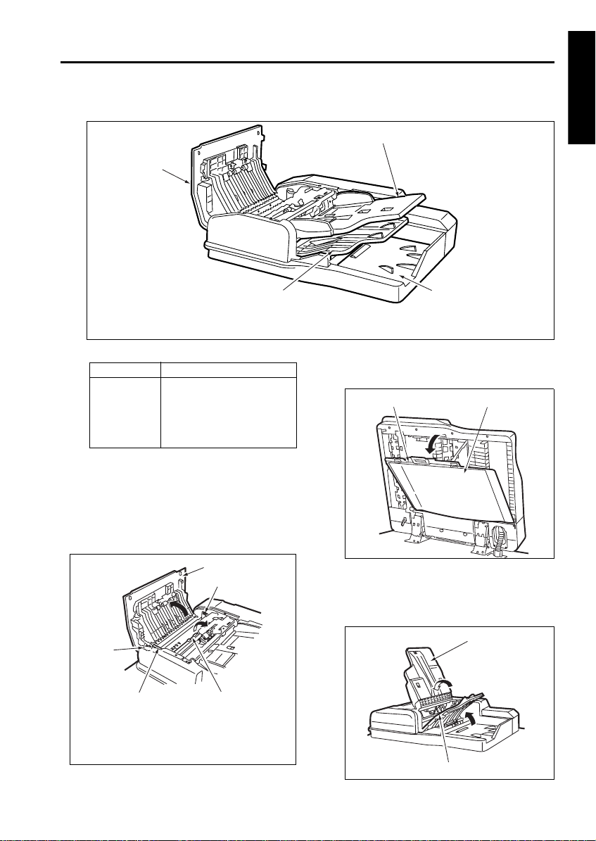
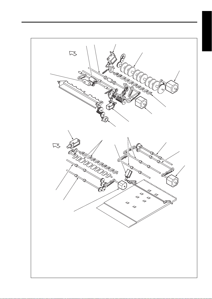
EXTERNAL SECTION
EDH-5
[1] Composition
4
1. Original feed tray
2. Original exit section (for small-size original)
[2] Mechanism
Mechanism Method
Jam removal *1Jam access cover
Jammed original release knob
Original conveyance guide
open/close lever
Platen guide
*1 Jam removal
If an original jam occurs during original feed,
open the Jam access cover and the original conveyance guide by releasing the original conveyance guide open/close lever, then turn the
jammed original release knob to remove the
jammed original.
1
2
4
RADF
1
3
3. Original exit tray (for large-size original
4. Jam access cover
If an original jam occurs during original reversal
operation, open the platen guide to remove the
jammed original .
Lock
If an original jam occurs during original exit, open
the original feed tray and original exit tray (for
large-size original) to remove the jammed original.
2
Platen guide
Original feed tray
2
1. Jam access cover
2. Original conveyance guide open/close lever
3. Original conveyance guide
4. Jammed original release knob
3
Original exit tray (for large-size original)
2-1
EDH-5
ORIGINAL FEED / CONVEYANCE / EXIT SECTION
RADF
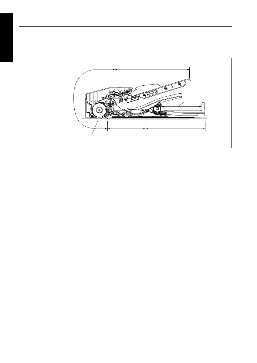
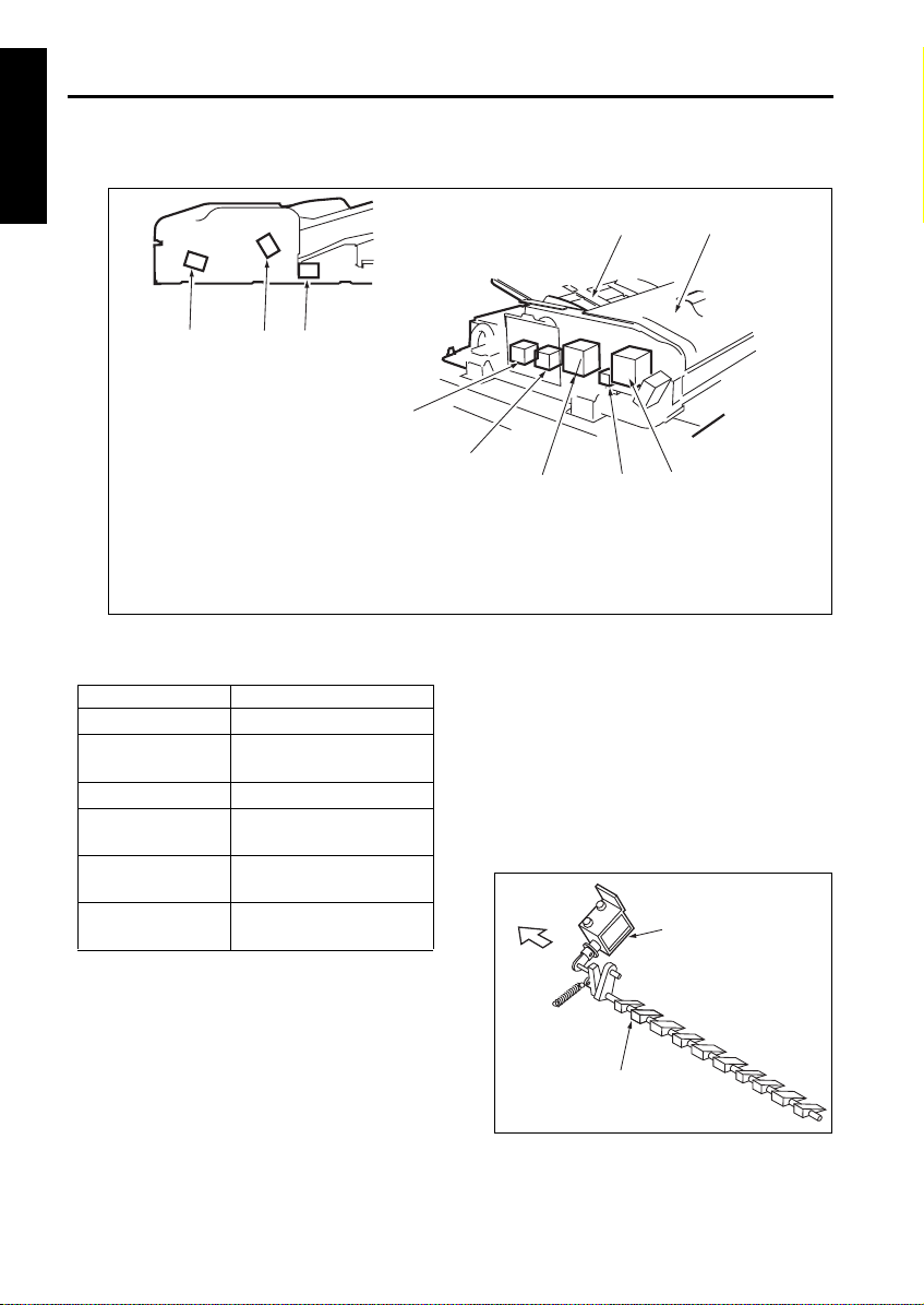
[1] Composition
3
1. Original exit gate solenoid (SD303)
2. Pressure roller release solenoid (SD302)
3. Flapper drive solenoid (SD301)
4. Original feed tray
5. Jam access cover
1
2
[2] Mechanism
Mechanism System
Original feed Original feed roller
Double feed prevention
Original conveyance Original conveyance roller
Original conveyance
path selection *1
Original reverse and
feed *2
Original exit path
selection *3
Double feed prevention roller
Separation roller
Flapper
Reversal roller pressure
Reversal roller rotation
Gate 1
Gate 2
4
10
9
8
6. Original conveyance motor (M301)
7. SDF switching solenoid (SD304)
8. Original feed motor (M302)
9. Original exit motor 1 (M304)
10. Original exit motor 2 (M305)
*1 Original conveyance path selection
In the two-sided copy mode, the original conveyance path selected after completion of scanning
differs depending on whether the image on the
front surface is to be printed or the image on the
back surface is to be printed. A flapper is used
to switch between these original conveyance
paths. The flapper drive solenoid (SD301) is
turned on/off to switch between the reversal section and the original exit section.
FRONT
7
5
6
Flapper drive SD
(SD301)
2-2
Flapper
EDH-5
*2 Reversed original feed
In the double-side copy mode, the original fed to
the reversal section is fed back by pressing the
the pressure roller against the reversal roller.
The pressure roller is driven by the pressure
roller release solenoid (SD302).
Pressure roller release solenoid (SD302)
Pressure roller
FRONT
*3 Original exit path switching
Large-size one-side and two-side originals are
exited to the original exit tray (for large-size original). On the other hand, small-size one-side and
two-side originals are exited to the original exit
section (for small-size original) through the reversal section. The small-size two-side original fed
to the reversal section is reversed and exited to
the small size original exit section. The original
exit path switching to which the original is exited
is performed by the gate 1 and gate 2, driven by
the on/off contol of the original exit gate solenoid
(SD303).
Original exit gate solenoid (SD303)
Original exit gate
FRONT
RADF
2-3
EDH-5
RADF
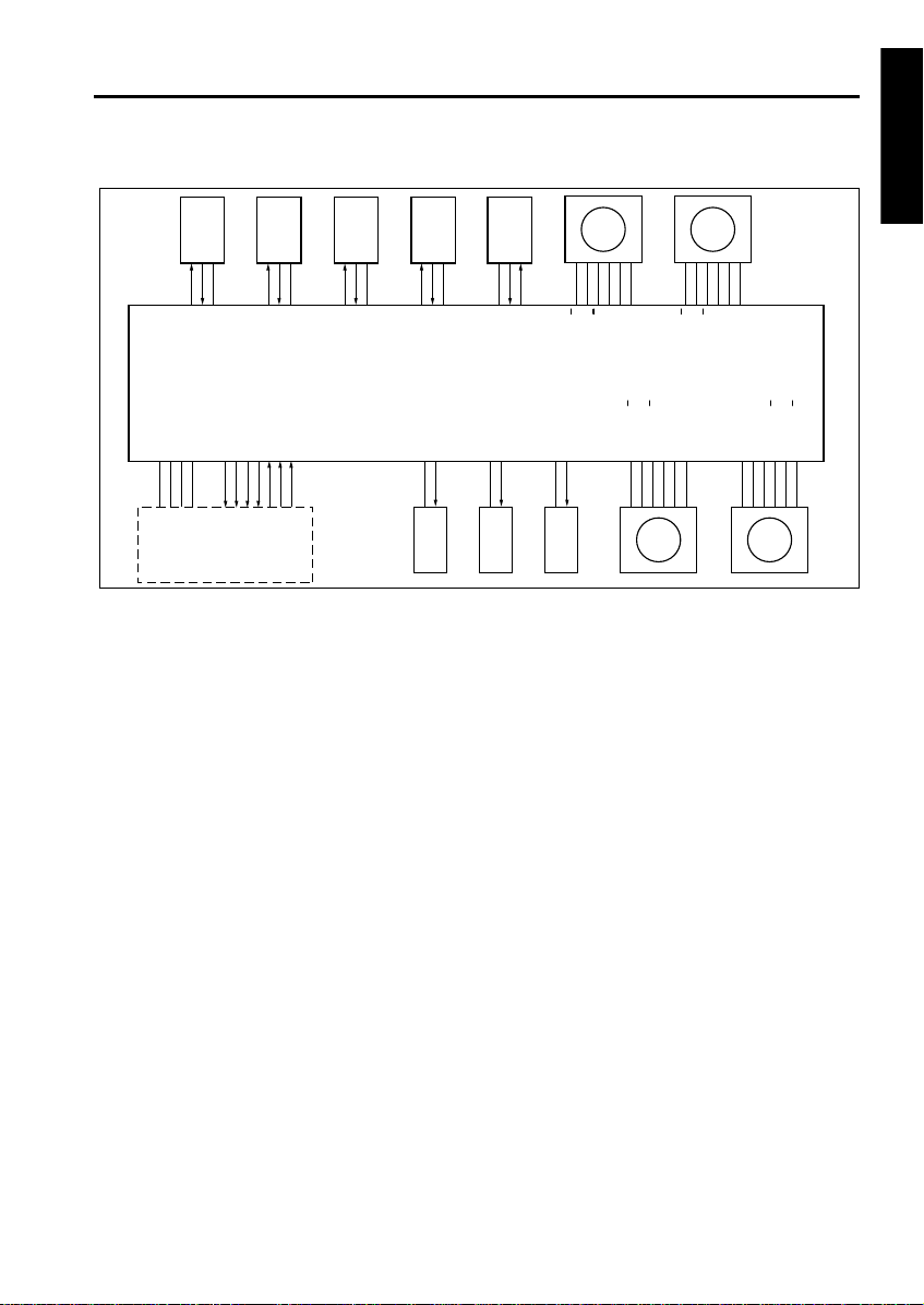
[3] Original Feed / Conveyance / Scan Control
PS312 PS311 PS308 PS301 PS316 PS315 PS305 PS306
MS301
5VDC
PS312
PS312 LED CONT
5VDC
SGND
PGND
24VDC
5VDC
PS311
PS311 LED CONT
DF VALID
DF CTS
DF DTR
DF RXD
DF RTS
DF TXD
DF DSR
5VDC
PS308
PS308 LED CONT
SD304
PS301
24VDC
SD304 DRIVE
MAIN BODY
riginal feed is performed by the original feed
roller and separation roller driven by M302 (original feed). Original conveyance is performed by
the original conveyance roller driven by M301
(original conveyance).
M301 and M302 are controlled by DFCB (RADF
control board).
1. Operation
a. Sensor activation at power ON
When SW1 (main) is ON, a sensitivity adjustment for PS306 (original registration detection),
PS308 (original conveyance detection), PS311
(original skew detection 1) and PS312 (original
skew detection 2) are performed. However,
automatic adjustment is not performed when the
RADF jam access cover is opened and MS301
(cover open/close MS) is OFF or when there is
original inside the RADF.
SGND
5VDC
SGND
PS316
5VDC
5VDC
PS315
SGND
5VDC
PS305
SGND
DFCB
PGND
FM301 LD
FM301 DRIVE
M302 DRIVE B
M302 DRIVE B
M302 DRIVE A
M302 DRIVE A
24VDC
24VDC
24VDC
24VDC
M301 DRIVE A
M301 DRIVE A
M301 DRIVE B
M301 DRIVE B
FM301 M302 M301 M303
b. Pressing original against roller
(1) First original
When a control signal is received from the main
body, M303 (tray up/down drive) turns forward to
raise the original feed tray. By this moment, the
original is raised and pressed against the original
feed roller.
After PS315 (tray upper limit detection) turns
ON, M303 stops after a predefined interval and
leaves the original feed tray raised in standby
state.
After M302 feeds the first original, M303 rotates
backward after a predefined time has elapsed
since it stopped, lowering the original feed tray,
and the pressure on the originals is released.
M303 continues to rotate backward for a predefined interval and then stops and remains in
standby state. At this point the original feed tray
waits without lowering to the bottom.
(2) Second and subsequent originals
When PS308 (original conveyance detection)
detects the leading edge of the first original and
turns ON, M303 that was in standby turns forward to raise the original feed tray and presses
the original against the original feed roller.
Subsequent operations are the same as for the
first original.
5VDC
PS306
PS306 LED CONT
M303 DRIVE B
M303 DRIVE B
M303 DRIVE A
MS301
M303 DRIVE A
24VDC
24VDC
24VDC
2-4

EDH-5
c. Original feed
M302 drives the original feed roller and separation roller.
When a control signal from the main body is
received, M302 rotates forward at low speed,
stops, and goes into standby.
When the original feed tray is raised and PS315
turns ON, M302 turns backward after a predefined interval to start original feed operation.
Then, when PS306 (original registration detection) detects the leading edge of the original and
turns ON, M302 switches to high speed forward
after a predefined interval to complete the original feed operation. After completing original feed
at high speed forward, M302 returns to low
speed forward and stops and goes into standby
when PS308 (original conveyance detection)
turns ON.
d. Original conveyance operation
When feeding the first original, M302 transports
the original to the conveyance roller by continuing to rotate at high and low speed.
During this time, M301 (original conveyance)
starts rotating forward at low speed at predefined
time after PS306 turns ON. The original reached
to the conveyance roller is then conveyed to the
scan position.
After starting conveyance of the first original,
M301 continues to rotate forward at low speed
until the last original is scanned.
e. Scan operation
The original is passed over the slit glass of the
optics unit by the low speed forward rotation of
M301 and read (scanned). While the original is
being scanned, original feed and conveyance
operations continue, triggered by the turning ON
of PS308.
f. Original mis-centering detection control
PS311 (original skew detection 1) and PS312
(original skew detection 2) are provided to detect
the inclined leading edge of the original during
conveyance.
PS311 and PS312 are placed at the front and
back of the pre-scan conveyance path and determine the inclination of the original by measuring
the difference in interval at which the leading
edge of the original turns these switches ON. A
skewed image caused by original inclination is
corrected through image processing so that the
image on the original is copied to a copy paper as
it is on the original.
g. SDF (Single Document Feeder) control
When SDF mode is selected, SD304 (SDF
switching SD) cut the drive force to the double
feed prevention roller to facilitate original feeding.
(1) ON timing
At the start of original feed
(2) OFF timing
When PS306 turns OFF
h. FM301 (ADF fan) operation
FM301 is used to cool M301 so that M301 does
not overheat during operation.
(1) ON timing
At the start of original feed
(2) OFF timing
When original ejection completed.
i. Jammed original ejection control
Upon receiving a control signal from the main
body, M301 rotates at high speed forward,
attempting to eject a jammed original in the
RADF.
2. Signals
a. Input signal
(1) MS301 (MS301 to DFCB)
Jam access cover open/close detection signal.
[L]: Cover opened
[H]: Cover closed
(2) PS301 (PS301 to DFCB)
RADF open/close detection signal.
[L]: RADF closed
[H]: RADF opened
(3) PS305 (PS305 to DFCB)
No original on original feed tray detection signal.
[L]: Original present
[H]: No original
(4) PS306 (PS306 to DFCB)
Original feed over original conveyance roller
detection signal.
[L]: Original present
[H]: No original
(5) PS308 (PS308 to DFCB)
Pre-scan position original detection signal.
[L]: Original present
[H]: No original
RADF
2-5

EDH-5
RADF
(6) PS311 (PS311 to DFCB)
Front side original skew detection signal.
[L]: Original present
[H]: No original
(7) PS312 (PS312 to DFCB)
Rear side original skew detection signal.
[L]: Original present
[H]: No original
(8) PS315 (PS315 to DFCB)
Original feed tray upper limit detection signal.
[L]: Tray at upper limit
[H]: Tray not at upper limit
(9) PS316 (PS316 to DFCB)
Original feed tray lower limit detection signal.
[L]: Tray at lower limit
[H]: Tray not at lower limit
(10) FM301 LD (FM301 to DFCB)
Goes [L] when FM301 reaches predefined
speed.
(11) DF TXD (MAIN BODY to DFCB)
Serial data for transmitting main body PRCB
operating status to RADF.
(12) DF RTS (MAIN BODY to DFCB)
Send the Request To Send signal from main
body PRCB to RADF.
(13) DF DSR (MAIN BODY to DFCB)
Send the Data Set Ready signal from main body
PRCB to RADF.
b. Output signals
(1) PS306 LED CONT (DFCB to PS306)
Reflective sensor PS306 LED ON/OFF control
signal.
[L]: PS306 LED ON
[H]: PS306 LED OFF
(2) PS308 LED CONT (DFCB to PS308)
Reflective sensor PS308 LED ON/OFF control
signal.
[L]: PS308 LED ON
[H]: PS308 LED OFF
(3) PS311 LED CONT (DFCB to PS311)
Reflective sensor PS311 LED ON/OFF control
signal.
[L]: PS311 LED ON
[H]: PS311 LED OFF
(4) PS312 LED CONT (DFCB to PS312)
Reflective sensor PS312 LED ON/OFF control
signal.
[L]: PS312 LED ON
[H]: PS312 LED OFF
(5) M301 DRIVE (DFCB to M301)
M301 A phase drive signal.
(6) M301 DRIVE (DFCB to M301)
M301 B phase drive signal.
(7) M302 DRIVE (DFCB to M302)
M302 A phase drive signal.
(8) M302 DRIVE (DFCB to M302)
M302 B phase drive signal.
(9) M303 DRIVE (DFCB to M303)
M303 A phase drive signal.
(10) M303 DRIVE (DFCB to M303)
M303 B phase drive signal.
(11) FM301 DRIVE (DFCB to FM301)
FM301 ON/OFF drive signal.
[L]: FM301 ON
[H]: FM301 OFF
(12) DF TXD (DFCB to MAIN BODY)
Serial data for transmitting RADF operating status to main body PRCB.
(13) DF DTR (DFCB to MAIN BODY)
Send the Data Terminal Ready signal from
RADF to main body PRCB.
(14) DF CTS (DFCB to MAIN BODY)
Send the Clear To Send signal from RADF to
main body PRCB.
(15) DF VALID (DFCB to MAIN BODY)
Image forming start signal.
A, A
B, B
A, A
B, B
A, A
B, B
2-6
EDH-5
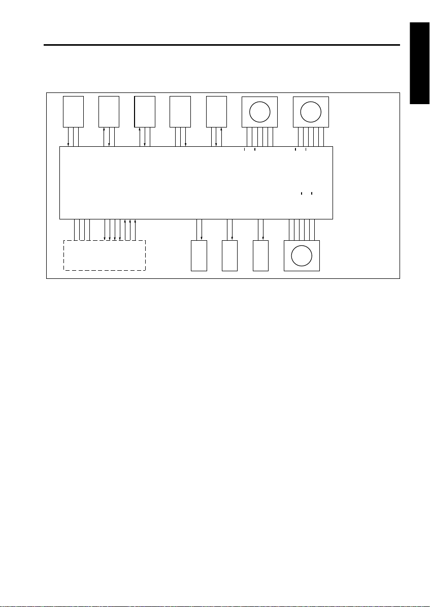
[4] Original Reversal and Conveyance Control
PS308 PS309 PS304 PS306
5VDC
PS308
PS308 LED CONT
5VDC
SGND
PGND
24VDC
MAIN BODY
In two side copy mode, an original that has been
scanned on the front side is conveyed to the original reversal section to be reversed and then rescanned.
At entrance to the original reversal section, there
is a flapper to switch the original conveyance
path. The flapper is driven by SD301 (flapper
drive). The reversal roller, which reverses and
conveys front-side-scanned original to the original reversal section and feeds that original to the
scan section again, is driven by M304 (original
exit 1). The original reversal roller which conveys
original to the original reversal section is driven
by M305 (original exit 2). When reversing and
feeding large originals, the pressure roller is
released by SD302 (pressure roller release).
M304, M305, SD301, and SD302 are controlled
by DFCB (RADF control board).
DF VALID
DF CTS
PS309
PS309 LED CONT
DF DTR
DF RXD
DF RTS
DF DSR
5VDC
DF TXD
5VDC
PS304
PS304 LED CONT
5VDC
PS306
PS306 LED CONT
DFCB
24VDC
SD301 DRIVE
SD301 SD302 SD303
PS313
5VDC
PS313
PS313 LED CONT
24VDC
SD302 DRIVE
M305 DRIVE B
M305 DRIVE B
24VDC
SD303 DRIVE
24VDC
24VDC
M305 DRIVE A
M305 DRIVE A
M302 DRIVE B
M304M305
24VDC
24VDC
M304 DRIVE B
M304 DRIVE B
M304 DRIVE A
M304 DRIVE A
M302 DRIVE B
M302 DRIVE A
M302 DRIVE A
24VDC
24VDC
24VDC
24VDC
M301 DRIVE A
M302 M301
M301 DRIVE A
M301 DRIVE B
M301 DRIVE B
MS) is OFF or when there is original inside the
RADF.
b. Original conveyance path switching/reversal
and original feed operation
(1) Small size original
SD301 is always OFF and the flapper is closed.
Therefore, the scanned original, whether it is single side or double side, is conveyed to the reversal section by M304 rotating at low speed
forward.
When copying the back side of a double-side
original, at predefined interval after PS309 (original reversal detection) detects the trailing edge
of original and turns OFF, M304 rotates backward at low speed and then at high speed to
reverse and feed the original. The reversed original is conveyed through the flapper and the
guides to the conveyance roller.
RADF
1. Operation
a. Sensor activation during power ON
When SW1 (main) is turned ON, a sensitivity
adjustment for PS309 (original reversal detection) and PS313 (original exit reverse detection)
are performed. However, automatic adjustment
is not performed when the RADF jam access
cover is opened and MS301 (cover open/close
2-7

EDH-5
RADF
(2) Large size original
The scanned-single side original is conveyed to
the original exit tray (large) by the original conveyance roller since SD301 is ON and the flapper
is opened.
In the case of large double-side original, the original is conveyed to the reversal section when
SD301 turns OFF after scanning the front side of
a double-side original . The original reaching the
reversal section does not fit in the reversal section so it is fed to the large-size original exit tray
side by the large original reversal roller, which is
driven by M305 (original exit 2). During this time,
SD303 (original exit gate) turns ON and the original exit gate is closed.
The original conveyed to the reversal section is
reversed and fed to the scan section again in the
same manner as small originals. Since the original reaching the conveyance roller does not exit
the reversal roller, SD302 is turned ON at predefined interval after high speed backward rotation of M304 to release the pressure roller for the
reversal roller. This enables original conveyance
using the conveyance roller. SD302 turns OFF
when it detects an image scan complete signal
from the main unit.
c. Two side original next original feed operation
(1) Small size original
During front-side scanning of two-side original,
the original feed of the next one is started by the
rotation of M302 (original feed) when PS306
(original registration detection) detects the trailing edge of the previous original and turns OFF.
The next original stops and waits in standby at
predefined interval after the turning ON of PS306
by its own leading edge.
When the back side of the first original is
scanned and PS308 (original conveyance detection) turns ON, M302 turns ON after a predefined
interval to resume original feed to scan the front
side of the next original. Thereafter, the same
operation is repeated.
(2) Large size original
During front-side scanning of double-side original, the original feed of the next original is started
when PS306 (original registration detection)
detects the trailing edge of the previous original
and turns OFF. The next original stops and waits
in standby at predefined interval after the turning
ON of PS306 by its own leading edge.
During ejection of previous original by reverse
and exit operation, when PS309 (original reversal detection) detects the trailing edge of the previous original and turns OFF, M302 turns ON
after a predefined interval to resume original
feeding to scan the front side of the next original.
Thereafter, the same operation is repeated.
Note: See [5] Original Exit Control for informa-
d. Jammed original ejction control
tion on reverse and exit operation.
Upon receiving a control signal from the main
unit, M304 and M305 rotate at high speed forward, attempting to eject a jammed original in the
RADF.
2. Signals
a. Input signals
(1) PS304 (PS304 to DFCB)
Reversal section original detection signal.
[L]: Original present
[H]: No original
(2) PS309 (PS309 to DFCB)
Reversal section entrance original detection signal.
[L]: Original present
[H]: No original
(3) PS313 (PS313 to DFCB)
Original ejection reversal section original detection signal.
[L]: Original present
[H]: No original
b. Output signal
(1) M304 DRIVE (DFCB to M304)
M304 A phase drive signal.
(2) M304 DRIVE (DFCB to M304)
M304 B phase drive signal.
(3) M305 DRIVE (DFCB to M305)
M305 A phase drive signal.
(4) M305 DRIVE (DFCB to M305)
M305 B phase drive signal.
A, A
B, B
A, A
B, B
2-8
EDH-5
[5] Original Exit Control
PS307 PS309 PS304
5VDC
SGND
PS307
5VDC
SGND
The ejection destination of the original that has
been scanned depends on the size of original.
The original exit roller 1 which conveys the original to the original exit tray (large) is driven by
M304 (original exit 1). The original exit roller 2
which conveys the original to the original exit
section (small) is driven by M305 (original exit 2).
The flapper which switches the original exit path
and the original exit gate are driven by SD301
(flapper drive) and SD303 (original exit gate)
respectively.
M304, M305, SD301, and SD303 are controlled
by DFCB (RADF control board).
1. Operation
a. Small size original exit operation
(1) Single-side original
Scanned original is conveyed to the reversal section since SD301 is OFF and the flapper is
closed.
Original conveyed to the reversal section is conveyed to the original exit gate by the reversal
roller which is driven by M304. During this time,
M304 drives the conveyance roller with low
speed forward rotation.
The original is conveyed to the original exit roller
2 since SD303 is OFF and the original exit gate
is opened. M305 drives the original exit roller 2
with low speed forward rotation and ejects the
PGND
24VDC
MAIN BODY
5VDC
PS309
PS309 LED CONT
DF VALID
DF CTS
DF DTR
DF RXD
DF RTS
DF DSR
5VDC
PS304
PS304 LED CONT
DF TXD
PS314 PS313
5VDC
5VDC
SGND
PS314
DFCB
PS313
PS313 LED CONT
24VDC
SD301 DRIVE
SD301 SD302 SD303
M305 M304
24VDC
24VDC
SD302 DRIVE
M305 DRIVE B
M305 DRIVE B
M305 DRIVE A
M305 DRIVE A
24VDC
SD303 DRIVE
24VDC
24VDC
M304 DRIVE B
M304 DRIVE B
M304 DRIVE A
24VDC
M301 DRIVE A
M301 DRIVE A
M301 DRIVE B
M301
24VDC
24VDC
M304 DRIVE A
M301 DRIVE B
original to the original exit section (small) with the
original surface facing down.
(2) Two-side original
A original that has been scanned on the back
side is conveyed to the original exit gate in the
same manner as single-side original. During this
time, SD303 is ON and the original exit gate is
closed. Therefore, the original is passed through
the original exit reversal roller, which is driven by
the low speed forward rotation of M305, and conveyed to the original exit reversal section.
M305 turns OFF when PS313 ( original exit
reverse detection) is turned OFF by the conveyed original. When SD303 turns OFF and the
original exit gate opens, M305 starts high speed
backward rotation after a predefined interval and
reverses the direction of the conveyed original.
Since the original exit gate is opened, the original
is conveyed to the original exit section (small)
rather than returning to the reversal section.
As a result, the two-side original is ejected with
the front side facing down.
RADF
2-9

EDH-5
RADF
b. Large size original ejection operation
(1) Single-side original
The scanned original is conveyed to the original
exit roller 1 by the conveyance roller since SD301
is ON and the flapper is opened. The original exit
roller 1 is driven by the low speed forward rotation
of M304 and the original is ejected to the original
exit tray (large) with the copy surface facing
down.
(2) Two-side original
The original that has been scanned on the back
side is conveyed to the reversal section since
SD301 is OFF and the flapper is closed.
When PS309 (original reversal detection)
detects the trailing edge of conveyed original,
SD301 (flapper drive SD) is turned ON and the
flapper is opened. Then, M304 (original exit 1)
rotates backward and the original is ejected to
the original exit tray (large size original) since the
flapper is open.
2. Signals
a. Input signals
(1) PS307 (PS307 to DFCB)
Original exit tray (large) entrance original detection signal.
[L]: Original present
[H]: No original
(2) PS314 (PS314 to DFCB)
Original exit section (small) entrance original
detection signal.
[L]: Original present
[H]: No original
2-10

EDH-5
[6] Original Size Detection Control
PS317 PS308 PS306
5VDC
SGND
PS317
5VDC
SGND
PGND
24VDC
MAIN BODY
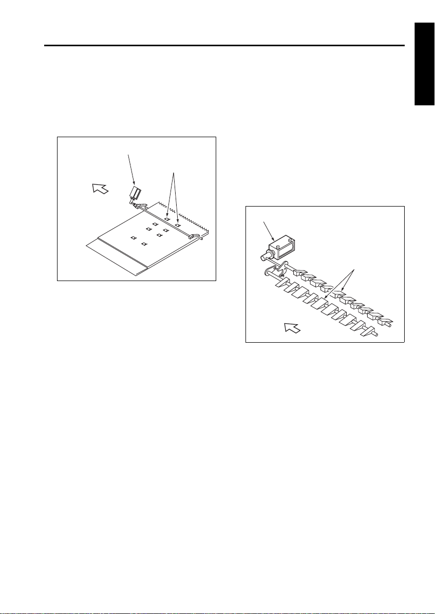
The size of the original placed in the original feed
tray is detected by PS302 (original size detection
1), PS303 (original size detection 2), and VR301
(original size detection).
PS302, PS303, and VR301 are controlled by
DFCB (RADF control board) through PTBD (tray
drive board). DFCB contains a non-volatile
memory for storing data such as timing data and
original size detection threshold.
1. Operation
a. Normal copy mode
DFCB detects the original size from the combination of the following signals:
(1) Drum axis direction size detection
A guide plate is connected to VR301 and the
resistance vary with the position of the guide
plate. This is used to determined the vertical
dimension of the original.
(2) Original feed direction size detection
The horizontal dimension of the original is
detected with the ON/OFF combination of
PS302 and PS303.
PS315
DF VALID
DF CTS
5VDC
PS308
PS308 LED CONT
DF DTR
DF RXD
DF TXD
DF RTS
DF DSR
5VDC
PS306
PS306 LED CONT
24VDC
24VDC
M301 DRIVE A
M301
PS302 PS303 VR301
5VDC
SGND
PS302
PTBD
5VDC
5VDC
PS303
SGND
PS303
PS302
VR301
SGND
DFCB
M301 DRIVE A
M301 DRIVE B
M301 DRIVE B
b. Mixed copy mode original size detection
Size detection during mixed copy mode is performed as follows:
(1) Drum axis direction size detection
The vertical dimension of the largest original is
determined by the position of the guide plate.
(2) The ON interval of PS306 (original registration
detection) after the original passes the registration roller is used to determine the horizontal
dimension of each original.
5VDC
VR301
RADF
SGND
2-11

EDH-5
RADF
(3) Original feed direction size detection
When the original is fed, M301 (original conveyance) turns forward and conveys the original to
the original exit tray (large). M301 continues to
rotate forward until PS306 detects the trailing
edge of the original and turns OFF. At this point,
the ON interval of PS306 is used to detect the
size of original in the feed direction.
1
1
2
4
1. Registration roller
2. PS 306 (Originalregistration detection)
3. Original conveyance roller
4. PS308 (Original conveyance detection)
After a predefined interval since PS306 turns
OFF, M301 changes direction and returns the
leading edge of the original conveyed to the original exit section to the scan wait position. The
trailing edge of the returned original is conveyed
to the original exit tray (large) due to the shape of
the conveyance guide plate.
The backward rotation of M301 stops at predefined interval after PS308 (original conveyance detection) detects the leading edge of the
original and turns OFF.
3
3
1. Scan stanby position
2. Original conveyance roller
3. PS 308 (Original conveyance detection)
Thereafter, read operation (scan) is performed in
the same manner as normal mode.
The size detection of the second and subsequent originals differ for single-side mode and
two-side mode.
• Single-side mode: After scanning of the previous original starts
• Two-side mode: When scanning of the back
side of the previous original starts
2
Second original
First original
2-12

EDH-5
c. Allowed size combination
( : Same size, : Same series, : Different
series, X: Mixing prohibited, -: Not supported)
Reference original (maximum-size
original detectable with guide plate)
A3 A4 B4 B5
A3
A4
B4
B5
A4R
A5
B5R
XX -
A5R
XXXXXXX -
B6R
XXXXXXX
A4RA5B5R A5R B6R
-------
-------
-----
-----
---
---
2. Signals
a. Input signals
(1) PS302 (PS302 to PTBD to DFCB)
Original horizontal dimension detection signal
[L]: Original present
[H]: No original
(2) PS303 (PS303 to PTBD to DFCB)
Original horizontal dimension detection signal
[L]: Original present
[H]: No original
(3) VR301 (VR301 to PTBD to DFCB)
Original vertical dimension detection signal
(4) PS317 (PS317 to DFCB to MAIN BODY)
Original size detection timing signal during
platen mode
Original size is detected when this signal
changes from [H] to [L].
RADF
2-13

RADF

C-403/C-404
LCT

LCT

CONTENTS
C-403/C-404
SAFETY AND IMPORTANT WARNING ITEMS
Refer to the Di850 service manual on page.......... S-1
1. OUTLINE
PRODUCT SPECIFICATIONS..................................1-1
CENTER CROSS-SECTIONAL DRAWING..............1-2
DRIVE SYSTEM DRAWING......................................1-3
[1] Paper feed drive section.............................1-3
[2] Stacked paper up/down wire drive
section........................................................1-4
2. UNIT EXPLANATION
PAPER FEED SECTION...........................................2-1
[1] Composition ...............................................2-1
[2] Mechanisms ...............................................2-1
[3] First paper feed control ..............................2-3
[4] Up/down plate drive control........................2-5
[5] Remaining paper detection/No paper
detection control.........................................2-6
LCT

LCT

1
OUTLINE
LCT

LCT

PRODUCT SPECIFICATIONS
C-403/C-404
[1] Type
Type:
Side mount type large volume paper feed tray
[2] Functions
Standard size paper :
A4LCT
• Metric area
A4 / B5 / 8.5 x 11
Wide paper (314 x 223 mm max.)
• Inch area
8.5 x 11 / A4
Wide paper (314 x 223 mm max.)
A3LCT
• Metric area
A3 / B4 / A4 / A4R / F4
11 x 17 / 8.5 x 14 / 8.5 x 11 / 8.5 x 11R
Wide paper (314 x 459 mm max.)
• Inch area
11 x 17 / 8.5 x 14 / 8.5 x 11 / 8.5 x 11R
A3 / B4 / A4 / A4R / F4
Wide paper (314 x 459 mm max.)
Maximum quantity:
4000 sheets (80 g/m
2
or 20lbs)
[3] Machine Data
Power source
24V DC/5V (supplied from the main body),
AC27.3V
Max. power consumption
A4LCT Max. 82 W
A3LCT Max. 100 W
Weight
A4LCT Approx. 30 kg
A3LCT Approx. 42 kg
Machine dimensions
A4LCT 430(W) x 639(D) x 690(H) mm
A3LCT 670(W) x 639(D) x 695(H) mm
[4] Maintenance
Maintenance:
Same as the main body
Machine life:
Same as the main body
[5] Operating Environment
Temperature:
10 to 30 °C (50 to 86 °F)
Humidity:
10 to 80 %RH
Note: The information herein may be subject to
change for improvement without notice.
LCT
1-1

C-403/C-404
CENTER CROSS-SECTIONAL DRAWING
LCT
1
7
1. Conveyance roller
2. Feed roller
3. Paper feed roller
4. Top cover
2
3
5. Up/down wire (the other side wire as well)
6. Up/down plate
7. Double feed prevention roller
4
5
6
1-2

DRIVE SYSTEM DRAWING
[1] Paper feed drive section
1
FRONT
4
C-403/C-404
2
LCT
3
6
5
7
FRONT
10
1. LT First paper feed SD (SD100)
2. Feed roller
3. Paper feed roller
4. Conveyance roller
5. LT First paper feed MC (MC 102)
1-3
9
8
6. LT paper feed motor (M101)
7. LT feed drive MC (MC101)
8. Paper feed roller
9. Feed roller
10. Double feed prevention roller

C-403/C-404
[2] Stacked paper up/down wire drive section
a. A4LCT
Up/down plate
LCT
LT up/down motor (M100)
FRONT
Up/down shaft
1-4

b. A3LCT
C-403/C-404
Up/down plate
LCT
LT up/down motor (M100)
FRONT
Up/down shaft
1-5

LCT

2
UNIT EXPLANATION
LCT

LCT

PAPER FEED SECTION
[1] Composition
2
1
3
C-403/C-404
9
8
7
10
11
LCT
6
5
1. LT paper feed motor (M101)
2. LT feed MC (MC101)
3. LT first paper feed MC (MC102)
4. Up/down wire (the other side wire as well)
5. Remaining paper detection gear
6. LT up/down motor (M100)
7. LT first paper feed SD (SD100)
[2] Mechanisms
Mechanism Method
Paper lifting *1 Wire drive
Paper feed Paper feed roller
No paper detection
Remaining paper
detection *2
Paper conveyance Roller conveyance
*1 Paper lifting
a. Up/down plate lifting drive operation
The up/down plate is lifted with the up/down
wires. When the top cover closes, LT up/down
motor (M100) rotates and the up/down plate connected to the up/down wires rises.
Photo sensor (PS108)
+actuator
Remaining paper detection gear+ photo sensor
(PS102, PS103, PS104,
PS105)
4
8. Paper dust removing brush
9. Conveyance roller
10. LT feed PS (PS106)
11. LT first paper feed PS (PS107)
12. Up/down plate
13. LT tray down drive switch (SW 100)
b. Up/down plate down drive operation
The up/down plate automatically lowers by 120
mm when the top cover is opened.
Subsequently, it is lowered by 120 mm each time
LT tray down drive switch (SW100) is pressed.
*2 Remaining paper detection
The LCT is equipped with a remaining paper
detection gear which rotates together with LT up/
down motor (M100) driving the up/down plate.
The remaining paper detection gear has an actuator to turn ON/OFF LT remaining paper detection PS1 (PS102), LT remaining paper detection
PS2 (PS103), LT remaining paper detection PS3
(PS104), and LT remaining paper detection PS4
(PS105).
13
12
2-1

C-403/C-404
LCT
Each sensor is turned ON/OFF according to the
rotating position of the remaining paper detection gear and since this is linked with the up/down
position of the up/down plate, the remaining
paper quantity in the LCT can be determined by
monitoring the ON/OFF of each sensor. The
remaining paper quantity detected with the four
sensors is displayed on the main body display.
a. A4LCT
8
(PS102)
(PS103)
(PS104)
(PS105)
2
7
3
4
5
6
1
1. LT up/down motor (M100)
2. Actuator
3. LT remaining paper detection PS1
4. LT remaining paper detection PS2
5. LT remaining paper detection PS3
6. LT remaining paper detection PS4
7. Remaining paper detection gear
8. Gear for M100
b. A3LCT
2
1
7
6
1. LT remaining paper detection PS1
(PS102)
2. LT remaining paper detection PS2
(PS103)
3. LT remaining paper detection PS3
(PS104)
4. Gear for M100
5. LT remaining paper detection PS4
(PS105)
6. Remaining paper detection gear
7. Gear for M100LT remaining paper
8. Actuator
3
4
5
2-2

C-403/C-404
[3] First paper feed control
UPOP_PS
S_GND
CONV_PS
S_GND
PR_PS
SIDOP_PS
CONT
CONT
CONT
5V
5V
24V
24V
24V
LT DB
HTR101
MAIN BODY
24V
PGND
5V
SGND
IO_DTXD
IO_UCLK
LCT_LATCH
IO_DCLK
ERR_OUT4
IO_URXD
ACK4
REQ4
The first paper is fed by the paper feed roller and
the feed roller driven by M101(LT paper feed) via
MC101(LT feed MC). The paper feed roller and
feed roller touche the paper when SD100 (LT first
feed) is ON, feeding the paper to the conveyance
roller. Then, SD100 (LT first paper feed) turns
OFF to release the paper feed roller and feed
roller from the paper. The conveyance roller is
also driven by M101, by turning ON MC102 (LT
first feed MC), paper is fed to the main body.
The related signals are: PS100 (LT top cover
open/close detection), PS106 (LT feed), PS107
(LT first feed), and PS110 (LT jam access door
open/close detection).
PS100
PS106
PS107
PS110
MC101
MC102
SD100
1. Operation
a. First paper feed timing
(1) Start of first paper feed
At predefined interval after the START button is
pressed.
(2) Start of second and subsequent papers
When PS106 (LT feed) is turned OFF by the preceding paper.
(3) OFF timing
When the main body M7 (paper exit) turns OFF.
b. Interlock
The power supply line of M101 (LT paper feed) is
equipped with MS101 (LT interlock/1) and
MS102 (LT interlock/2). When the top cover is
opened, MS101 turns OFF, and when the jam
access door is opened MS102 turns OFF,
thereby cutting off the power supply to M101.
Furthermore, the top cover is equipped with
PS100 (LT top cover open/close detection) and
the jam access door is equipped with PS110 (LT
jam access door open/close detection) and
when either of these doors is opened during
paper feed, the M101 drive signal is turned OFF
to stop the paper feed operation.
c. Internal heater
The LCT is equipped with HTR101 (LT internal
heater) to protect the paper from humidity.
HTR101 is directly controlled by the main body
PRCB (printer control board) rather than by the
LTDB (LT drive board).
LCT
2-3

C-403/C-404
2. Signals
a. Input signals
(1) UPOP_PS (PS100 to LTDB)
Top cover open/close detection signal
[L]: Cover opened
[H]: Cover closed
(2) CONV_PS (PS106 to LTDB)
Conveyance roller exit paper detection signal
[L]: Paper detected
LCT
[H]: Paper not detected
(3) PR_PS (PS107 to LTDB)
Conveyance roller entrance (pre-registration
position) paper detection signal
[L]: Paper detected
[H]: Paper not detected
(4) SIDOP_PS (PS110 to LTDB)
Jam access door open/close detection signal
[L]: Door opened
[H]: Door closed
(5) LCTM_EM (M101 to LTDB)
M101 rotation error detection signal
[L]: M101 rotating
[H]: M101 not rotating
(6) IO_DTXD (MAIN BODY to LTDB)
Serial data to transmit main body PRCB (printer
control board) operating status to LTDB
(7) LCT_LATCH (MAIN BODY to LTDB)
IO_DTXD signal latch signal
(8) IO_DCLK (MAIN BODY to LTDB)
IO_DTXD signal clock signal
(9) ERR_OUT4 (MAIN BODY to LTDB)
Signal to notify LTDB (LT drive board) when there
is error in the main body
(10) ACK4 (MAIN BODY to LTDB)
Serial data transmission enable signal from LCT
to main body PRCB (printer control board)
b. Output signals
(1) CONT (LTDB to MC101)
MC101 (LT feed MC) ON/OFF drive signal
[L]: MC101 ON
[H]: MC101 OFF
(2) CONT (LTDB to MC102)
MC102 (LT first paper feed MC) ON/OFF drive
signal
[L]: MC102 ON
[H]: MC102 OFF
(3) CONT (LTDB to SD100)
SD100 ( LT first paper feed) ON/OFF drive signal
[L]: SD100 ON
[H]: SD100 OFF
(4) LCTM_CONT (LTDB to M101)
M101 (LT paper feed) ON/OFF control signal
[L]: M101 ON
[H]: M101 OFF
(5) IO_URXD (LTDB to MAIN BODY)
Serial data to transmit the LTDB (LT drive board)
operating status to main body PRCB
(6) IO_UCLK (LTDB to MAIN BODY)
IO_URXD signal clock signal
(7) REQ4 (LTDB to MAIN BODY)
Serial data send request signal from LCT to main
body PRCB
(8) LCTM_CLK (M101 to LTDB)
M101 (LT paper feed) rotational speed control
clock signal
(9) LCTM_F/R (M101 to LTDB)
M101 (LT paper feed) rotational direction indication signal
This machine always indicates [H]: normal rotation.
2-4

C-403/C-404
[4] Up/down plate drive control
LT D B
PGND
SGND
IO_DTXD
IO_UCLK
LCT_LATCH
IO_DCLK
ERR_OUT4
IO_URXD
ACK4
REQ4
24V
5V
MAIN BODY
When the top cover opens or closes, M100 (LT
up/down motor) rotates forward or backward to
move the up/down plate up or down. The up/
down plate descends by 120 mm each time
SW100 (LT tray down drive) is pressed while the
top cover is opened.
The related signals are PS100 (LT top cover
open/close detection), PS101 (LT lower limit
detection), and PS109 (LT upper limit detection).
1. Operation
a. Up/down plate descend timing
(1) ON timing
When the top cover is opened and PS100 (LT top
cover open/close detection) is turned OFF, M100
rotates backward to lower the up/down plate.
When SW100 (LT tray down drive) turns ON by
pressing, M100 rotates backward to move the
up/down plate down.
(2) OFF timing
M100 turns OFF at predefined interval after
PS100 turns OFF or SW100 turns ON. This in
turn lowers the up/down plate by 120 mm.
(3) Others
The up/down plate descends by 120 mm each
time SW100 is pressed until PS101 turns ON to
indicate the bottom limit of the up/down plate.
UPOP_PS
S_GND
S_GND
DW_SW
UP_PS
S_GND
5V
5V
SIG
5V
D1
D2
PS100
PS101
SW100
PS109
M100
b. Up/down plate ascend timing
(1) ON timing
When the top cover is closed and PS100 (LT top
cover open/close detection) is turned ON, M100
(LT UP/DOWN) rotates forward to raise the up/
down plate.
(2) OFF timing
When the up/down plate rises and PS109 (LT
upper limit detection) turns ON to indicate the
detection of the topmost paper, M100 (LT UP/
DOWN) turns OFF and stops the up/down plate.
The up/down plate also stops when the top cover
is opened and PS100 (LT top cover open/ close
detection) turns OFF.
2. Signals
a. Input signals
(1) SIG (PS101 to LTDB)
Up/down plate lower limit detection signal
[L]: Up/down plate not at lower limit
[H]: Up/down plate at lower limit
(2) UP_PS (PS109 to LTDB)
Up/down plate upper limit detection signal
[L]: Up/down plate not at upper limit
[H]: Up/down plate at upper limit
(3) DW_SW (SW100 to LTDB)
SW100 (LT tray down switch) ON/OFF detection
signal
[L]: SW100 ON
[H]: SW100 OFF
b. Output signal
(1) D1, 2 (LTDB to M100)
M100 (LT UP/DOWN) drive signal
These signals switches the direction of the drive
current to control the rotation direction of M100.
LCT
2-5

C-403/C-404
[5] Remaining paper detection/No paper
detection control
LT D B
LCT
PGND
SGND
IO_DTXD
IO_UCLK
LCT_LATCH
IO_DCLK
ERR_OUT4
IO_URXD
ACK4
REQ4
24V
5V
MAIN BODY
The remaining paper quantity is detected by
PS102 (LT remaining paper detection 1), PS103
(LT remaining paper detection 2), PS104 (LT
remaining paper detection 3), and PS105 (LT
remaining paper detection 4) and no paper
detection is made by PS108 (LT no paper detection).
The signals detected by these sensors are controlled by LTDB (LT drive board) and displayed on
the main body display.
1. Operation
a. Remaining paper detection control
The remaining paper quantity is determined from
the ON/OFF combination of sensors PS102 (LT
remaining paper detection 1), PS103 (LT remaining paper detection 2), PS104 (LT remaining
paper detection 3), and PS105 (LT remaining
paper detection 4) which detect the rotational
position of M100 (LT UP/DOWN) that is driving
the up/down plate. Each sensor turns ON or
OFF according to the position of the remaining
paper detection gear which is linked with the
rotation of M100.
The remaining paper quantity is detectable at
eight levels, but it is displayed on the main body
display as five levels.
S_GND
S_GND
S_GND
S_GND
0_PS
S_GND
5V
SIG
5V
SIG
5V
SIG
5V
SIG
5V
D1
D2
PS102
PS103
PS104
PS105
PS108
M100
<Remaining paper quantity and display>
Stacked
paper
quantity
PS102 PS103 PS104 PS105
Remaining
paper quantity
display
0 to 700 OFF OFF OFF OFF 1 flashing
701 to 1200 ON OFF OFF OFF 1 on
1201 to 1700 ON ON OFF OFF 2 on
1701 to 2200 ON ON ON OFF 2 on
2201 to 2700 ON ON ON ON 3 on
2701 to 3200 OFF ON ON ON 3 on
3201 to 3700 OFF OFF ON ON 4 on
3701 or more OFF OFF OFF ON 4 on
Caution:The remaining paper quantity is indicated on
the control panel with four horizontal bars.
Stacked paper quantity differs depending on
the thickness of the paper.
b. No paper detection control
When there is no more paper inside the LCT,
PS108 (LT no paper detection) turns ON and a
message is displayed on the main body display.
2. Signals
a. Input signals
(1) SIG (PS102 to LTDB)
Remaining paper detection gear rotational position detection signal
[L]: PS102 OFF
[H]: PS102 ON
(2) SIG (PS103 to LTDB)
Remaining paper detection gear rotational position detection signal
[L]: PS103 OFF
[H]: PS103 ON
(3) SIG (PS104 to LTDB)
Remaining paper detection gear rotational position detection signal
[L]: PS104 OFF
[H]: PS104 ON
(4) SIG (PS105 to LTDB)
Remaining paper detection gear rotational position detection signal
[L]: PS105 OFF
[H]: PS105 ON
(5) 0_PS (PS108 to LTDB)
LCT no paper detection signal
[L]: No paper
[H]: Paper present
2-6

FN-7/FN-115
FNS

FNS

CONTENTS
FN-7/FN-115
SAFETY AND IMPORTANT WARNING ITEMS
Refer to the Di850 service manual on page.......... S-1
1. OUTLINE
PRODUCT SPECIFICATIONS..................................1-1
CENTER CROSS-SECTIONAL DRAWING..............1-3
DRIVE SYSTEM DIAGRAM ......................................1-4
[1] Paper Conveyance Drive ...........................1-4
[2] Stacker Drive..............................................1-5
[3] Folding Drive (FN-7 only) ...........................1-6
PAPER CONVEYANCE PROCESS..........................1-7
[1] Paper Conveyance Process.......................1-7
[2] Non-Sort Mode ...........................................1-8
[3] Sort, Group Mode .......................................1-9
[4] Sub-tray Mode..........................................1-10
[5] Staple Mode .............................................1-11
[6] Booklet Mode (FN-7 only) ........................1-13
2. UNIT EXPLANATION
EXTERNAL SECTION...............................................2-1
[1] Composition ...............................................2-1
[2] Mechanisms ...............................................2-1
CONVEYANCE SECTION.........................................2-2
[1] Composition ...............................................2-2
[2] Mechanisms ...............................................2-3
[3] M1 (FNS Conveyance) Control ..................2-7
[4] Gate Control ...............................................2-9
[5] M13 (Stacker Entrance) Control...............2-11
[6] M5 (Alignment Plate/Upper) Control ........2-13
[7] M15 (Alignment Plate/Lower) Control
(FN-7 only) ...............................................2-14
[8] M2 (Roller Shift) Control...........................2-15
[9] M7 (Paper Exit Roller) Control .................2-16
[10] SD4 (Paper Exit Opening) Control...........2-18
[11] M8 (Paper Exit Opening) Control .............2-19
STAPLER UNIT.......................................................2-20
[1] Composition .............................................2-20
[2] Mechanisms .............................................2-21
[3] Stapler Control .........................................2-25
MAIN TRAY UNIT....................................................2-29
[1] Composition .............................................2-29
[2] Mechanisms .............................................2-29
[3] Main Tray Up/Down Control.....................2-29
FOLDING UNIT (FN-7 ONLY).................................2-31
[1] Composition .............................................2-31
[2] Mechanisms .............................................2-32
[3] Folding-Unit Control .................................2-33
FNS

FNS

1
OUTLINE
FNS

FNS

PRODUCT SPECIFICATIONS
FN-7/FN-115
[1] Type
FN-115:
Finishing device implementing offset collation
(sort,group), stapling, and sub-tray eject
FN-7:
Finishing device implementing offset collation(sort,group), stapling, sub-tray eject (booklet), stapling-and-folding, and folding
[2] Functions
Type of Paper: Same as the main body
Paper Size :
FN-7/115
Non-
Sort/
group
Staple
sort
A3
B4
F4
A4R
A/B
A4
stan-
B5R
dards
B5
A5R
A5
B6R
11 x 17
8.5 x 14
8.5 x
By
11R
inch
8.5 x 11
5.5 x
8.5R
5.5 x 8.5
Wide
paper
Paper Stacking Capacity (80 g/m
Sub-tray exit mode:
Maximum 200 sheets (same-size sheets only)
Non-Staple, Sort, and Group modes:
Maximum 1500 sheets
(A3, B4, F4, 11 x 17, 8.5 x 14)
Maximum 3000 sheets
(A4, A4R, B5, B5R, 8.5 x 11, 8.5 x 11R)
Maximum 500 sheets
(A5, A5R, B6R, 5.5 x 8.5, 5.5 x 8.5R)
FN-7
only
Sub-
Book-
tray
2
or 20 lbs):
Staple Mode:
Maximum 1000 sheets(same size sheets only)
Main-Tray Capacity
* : FN-7 only
Original pages
A3, 11 x 17,
A5, 5.5 x 8.5
Other paper
types
2 to 9 50 stacks 100 stacks
10 to 20 50 stacks 50 stacks
21 to 30 30 stacks 30 stacks
31 to 40 25 stacks 25 stacks
41 to 50 20 stacks 20 stacks
51 to 60 — 15 stacks *
let
61 to 100 — 10 stacks *
Booklet Mode (FN-7 only):
• Stapling-and-folding
20 booklets of 5 folded sheets each
(20 pages/ booklet; eq. to 400 pages).
• Folding
33 booklets of 3 folded sheets each
FNS
(12 pages/ booklet; eq. to 396 pages)
Paper curling: 10mm or less
Amount of curl
Paper (5 sheets)
Booklet-mode folding level (FN-7 only):
Height of folding
Original
pages
0 to 5
6 to 10
11 to 20
A3, 11 x 17
25mm or
less
50mm or
less
Not
specified*
(80 g/m2 or 20 lbs)
B4,
8.5 x 14
25mm or
less
50mm or
less
Not
specified*
A4R,
8.5 x 11R
25mm or
less
Not
specified*
Not
specified*
* The height of folding may be larger after exit,
although the booklet must be folded with ease
manually.
Amount of sort offsetting:
30 mm (after sorting and grouping)
1-1

FN-7/FN-115
[3] Staple Mode
Number of sheets to be stapled:
FN-115:
50 sheets maximum (the length in the paper
feed direction is 400 mm or more)
100 sheets maximum (except for paper mentioned above in parentheses)
* The height must be 10 mm or less when using
80g/m2 or 20 lbs quality paper.50 sheets or
less (the height must be 5mm or less when
using 80g/m
FN-7:
50 sheets maximum
* The height must be 5 mm or less when using
80g/m2 or 20 lbs quality paper.
Staple position:
* : adjustment possible
FNS
A 9.0 ± 3 mm * 8.5 ± 3 mm *
B 9.0 ± 3 mm 8.5 ± 3 mm
C 82.5 ± 3 mm 82.5 ± 3 mm
D 9.0 ± 3 mm * 8.5 ± 3 mm *
E 15.0 ± 3 mm 8.5 ± 3 mm
2
or 20lbs quality paper)
FN-115 FN-7
[4] Booklet Mode (FN-7 only)
Stapling-and-fold:
Maximum 20 sheets (80 g/m
Maximum 19 sheets (80 g/m
+ 1 sh eet ( 200 g /m
Folding:
Maximum 3 sheets (80 g/m
2
2
2
2
or 20 lbs paper)
[5] Option
Cover Inserter B:
(Cover sheet feeder)
[6] Machine Specifications
Power source:
24 V, 5 VDC (supplied from the main body)
Maximum power consumption:
100 VA
Weight:
FN-115: Approx. 65 kg
FN-7: Approx. 80 kg
External Dimensions:
656
85
781
367
or 20 lbs paper)
or 20 lbs paper)
or 45 lbs paper)
1151
1095
Single staple
(rear)
Booklet mode (stitch-and-fold, FN-7 only)
Staple capacity: 5000 staples/cartridge
Binding Staples:
A
Binding staples 100 sheets 50 sheets
Two staples
FN-115 FN-7
A 13.5 mm 12.0 mm *
B
B 13.2 mm 8.0 mm
Single
staple
(front)
(Unit : mm)
[7] Maintenance
Maintenance procedures:
Same as the main body
Service life:
Same as the main body
[8] Operating Environment
Temperature:
10 to 30 °C (50 to 86 °F)
Humidity:
10 to 80 % RH
Note: The information herein may be subject to
change for improvement without notice.
1-2

CROSS SECTION DIAGRAM
4
1
2
14
13
3
FN-7/FN-115
5
6
7
8
9
FNS
10
11
12
1. Main tray
2. Paper exit unit
3. Shift unit
4. Sub-tray
5. Gate
6. Sub-tray gate
7. By-pass gate
Area within dotted lines: FN-7 only.
8. Flat-stapling stopper
9. Stapler unit
10. Stapling and folding stopper
11. Folding unit
12. Folding stopper
13. Booklet tray
14. Stacker unit
1-3

FN-7/FN-115
DRIVE SYSTEM DIAGRAM
[1] Paper Conveyance Drive
1
2
3
4
13
12
11
5
6
FNS
10
9
8
1. Sub-tray paper exit roller (B)
2. Sub-tray paper exit roller (C)
3. Sub-tray paper exit roller (A)
4. Nip paper exit roller
5. Paper exit roller
6. Paper exit roller motor (M7)
7. Intermediate conveyance roller
7
8. FNS conveyance motor (M1)
9. Conveyance roller (A)
10. Conveyance roller (B)
11. Conveyance roller (C)
12. Conveyance roller (D)
13. Conveyance slide shaft
1-4

[2] Stacker Drive
(FN-115)
(FN-7)
9
8
7
6
1. Nip paper exit roller
2. Paper exit roller
3. Paper exit roller motor (M7)
4. Coupling
5. Stacker entrance motor (M13)
9
1
5
6. Swivel roller
7. Stacker entrance roller
8. Paper exit belts
9. Paper exit arms
1
2
4
2
FN-7/FN-115
3
FNS
3
8
7
6
1. Nip paper exit roller
2. Paper exit roller
3. Paper exit roller motor (M7)
4. Coupling
5. Stacker entrance motor (M13)
4
5
6. Paper exit arms
7. Swivel roller
8. Stacker entrance roller
9. Paper exit belts
1-5

FN-7/FN-115
[3] Folding Drive (FN-7 only)
7
6
FNS
1. Pressure roller (A)
2. Pressure roller (B)
3. Folding conveyancebelts
4. Folding conveyance motor (M20)
5. Folding knife motor (M19)
9
8
5
4
1
2
3
6. Folding knife
7. Folding conveyance roller
8. Folding roller (A)
9. Folding roller (B)
1-6

PAPER CONVEYANCE PROCESS
[1] Paper Conveyance Process
The FNS (finisher) provides four paper paths, as shown in the diagram below.
Face-up and face-down inversion is handled by at the main-body side by the main body’s exit page inverter.
Non-SortMode
Sub-tray
Main tray
FN-7/FN-115
FNS
Booklet tray
Paper conveyance path Finishing mode
1
2
3
4
Non-sort, Sort, Group modes
Sub-tray mode
Staple mode
Booklet mode (FN-7 only)
1-7

FN-7/FN-115
[2] Non-Sprt Mode
Exit to main tray
A paper exited from the main body is conveyed and exited to the main tray.
1
8
7
FNS
1. Gate
2. Sub-tray gate
3. Co nveyance roller (B)
4. Co nveyance roller (A)
6
5. C onveyance roller (C)
6. C onveyance roller (D)
7. Paper exit roller
8. Main tray
2
3
4
5
1-8

FN-7/FN-115
[3] Sort, and Group Modes
Exit to main tray
Paper exited from the main body is conveyed and exited to the main tray. This mode has an off-set function
that allows each page of the even-numbered sets to be exited with the paper shifted 30mm to the rear..
Off-set- Function
(1) The odd-numbered pages are exited to the main tray with the image side face down.
(2) The even-numbered pages are shifted 30mm to the rear by the conveyance slide shaft of the shift unit and
then exited to the main tray.
30mm
1
2
10
9
3
8
7
4
5
6
FNS
1. Shift unit
2. Conveyance slide shaft
3. Gate
4. Sub-tray gate
5. C onveyance roller (B)
6. Conveya nce rol ler (A)
7. Conveyance roller (C)
8. Conveya nce rol ler (D)
9. Paper exit roller
10. Main tray
1-9

FN-7/FN-115
[4] Sub-tray Mode
The sub-tray gate opens. Paper exited from the main body is conveyed and exited to the sub-tray.
7
6
1
5
FNS
1. Sub-tray paper exit roller (C)
2. Sub-tray gate
3. Conveyance roller (B)
5. Sub-tray paper exit roller (A)
6. Sub-tray paper exit roller (B)
7. Sub-tray
2
3
4
4. Conveyance roller (A)
1-10

[5] Staple Mode
(1) The gate switches to the staple mode.
(2) For A4R paper and above, the paper exit opening opens.
(3) The first set of paper is conveyed and stacked.
1) The stacker section roller sends the paper to the flat-stapling stopper and the paper is lined up in the
length wise direction.
2) The upper alignment plate lines up paper in the widthwise direction.
3) Paper is stapled.
4) The first set is conveyed by the paper exit arm and exited to the main tray.
FN-7/FN-115
3
1
F
i
r
s
t
s
t
a
p
l
e
d
s
e
t
2
4
5
6
FNS
7
16
15
8
9
14
10
11
13
12
1. Paper exit opening
2. Intermediate conveyance roller
3. Gate
4. Conveyance roller (C)
5. Sub-tray gate
6. Conveyance roller (B)
7. Conveyance roller (A)
8. By-pass gate
9. Stacker entrance roller
10. Swivel roller
11. Flat-stapling stopper
12. Paper exit arm
13. Stapler unit
14. Paper exit belt
15. Alignment plate upper
16. Main tray
1-11

FN-7/FN-115
(4) The second and subsequent sets of paper are conveyed and stacked.
1) The first page stops in the stacker entrance with the by-pass gate opened. The stacker entrance roller stops
to wait for the previous stack to be exited.
2) The by-pass gate is closed and the second page is stacked on top of the first.
3) Once the previous stack has exited, the stack entrance roller rotates and the first and second pages are
simultaneously sent to the stacker.
* The above steps (1) to (3) are for paper to a maximum of A4 size.
4) The stacker section roller sends the paper to the flat-stapling stopper and the paper is lined up in the length
wise direction.
5) The upper alignment plate lines up paper in the widthwise direction.
6) When all paper is conveyed to the stacker, the paper is stapled.
7) The second and subsequent sets are conveyed by the paper exit arm and the paper is exited to the main
tray.
3
FNS
1
F
i
r
s
t
s
t
a
p
l
e
d
s
e
t
2
4
5
6
7
18
17
16
8
9
10
11
15
14
1. Paper exit opening
2. Intermediate conveyance roller
3. Gate
4. Conveyance roller (C)
5. Sub-tray gate
6. Conveyance roller (B)
7. Conveyance roller (A)
8. By-pass gate
9. First sheet
10. Stacker entrance roller
11. Swivel roller
12. Flat-stapling stopper
13. Paper exit arm
14. Stapler unit
15. Paper exit belt
16. Second sheet
17. Alignment plate upper
18. Main tray
12
13
1-12

FN-7/FN-115
[6] Booklet Mode (FN-7 only)
(1) The gate switches to the staple mode.
(2) The paper exit opening opens.
(3) The paper is conveyed and stacked.
(4) The stacker section roller sends the paper to the stapling-and-folding stopper and the paper is lined up in the
lengthwise direction.
(5) The upper and lower alignment plate lines up paper in the widthwise direction.
(6) If stapling-and-folding has been selected, staple the stack.
(7) Release the stapling-and-folding stopper and convey the stack to the folding unit by the paper exit belt.
(8) Convey the stack up to the folding stopper, fold it with the folding knife, and eject to the booklet tray.
1
22
21
20
17
16
15
1. Intermediate conveyance roller
2. Gate
3. Conveyance roller (C)
4. Sub-tray gate
5. Conveyance roller (B)
6. Conveyance roller (A)
7. Stacker entrance roller
8. Swivel roller
9. Alignment plate/lower
10. Stapling and folding stopper
11. Folding conveyance roller
18
13
14
2
7
8
9
19
12. Folding conveyance belt
13. Folding knife
14. Folding roller (B)
15. Folding stopper
16. Booklet tray
17. Pressure roller (B)
18. Pressure roller (A)
19. Folding roller (A)
20. Stapler unit
21. Paper exit belt
22. Upper alignment plate
3
4
5
6
FNS
10
11
12
1-13

FNS

2
UNIT EXPLANATION
FNS

FNS

EXTERNAL SECTION
[1] Composition
1
9
8
7
6
FN-7/FN-115
2
3
1. Sub-tray
2. Paper exit cover
3. Top cover
4. Front cover
4
5
5. Front side cover
6. Booklet tray (FN-7 only)
7. Paper exit stopper plate
8. Rear cover
9. Main tray
FNS
[2] Mechanism
Mechanism Method
Jam pmrocessing *1Roller rotation
Guide plate open/close
*1 Jam processing
To remove a jamming paper in the conveyance
unit, open the front cover, rotate the conveyance
roller, then open each guide plate.
To remove a jamming paper in the stapler unit,
open the front cover, then pull out the stapler sec-
tion.
To remove a jamming paper in the folding unit,
open the front cover, rotate the conveyance
roller, then open the guide plate.
2-1
3
1. Conveyance unit
2. Folding unit
3. Stapler unit
1
2

FN-7/FN-115
CONVEYANCE SECTION
[1] Composition
24
23
22
21
20
1
2
FN-7 / FN-115 Rear View
3
4
5
6
7
19
FNS
18
Area within dotted lines: FN-7 only
17
16
15
1. Deceleration roller
2. FNS conveyance motor (M1)
3. Conveyance slide shaft
4. Paper exit roller motor (M7)
5. Nip paper exit roller
6. Paper exit roller (Sponge roller)
7. Conveyance roller (D)
8. Stacker entrance motor (M13)
9. Stacker entrance roller
10. Paper exit belt
11. Folding roller (A)
12. Pressure roller (A)
13. Pressure roller (B)
14. Folding roller (B)
15. Folding conveyance motor (M20)
16. Folding conveyance belt
17. Folding conveyance roller
18. Intermediate conveyance roller
19. Conveyance roller (C)
20. Conveyance roller (A)
21. Conveyance roller (B)
22. Sub-tray paper exit roller (A)
23. Sub-tray paper exit roller (B)
24. Sub-tray paper exit roller (C)
8
9
10
11
12
13
14
2-2

FN-7/FN-115
[2] Mechanism
Mechanism Method
Paper conveyance *1 Motor + roller
Path switching *2 Gate /sub-tray
Shift mechanism of
the shift unit *3
Stacker unit *4 Paper exit belt + roller
Stapler paper exit *5 Pressure rollers driven by
Sub-tray exit *6 Deceleration roller re lease
Folding *7 Folding knife
*1 Gate Switching
Paper Conveyance
Paper conveyance is carried out by conveyance
rollers (A), (B), (C), and (D); the intermediate
conveyance roller; the conveyance slide shaft;
and sub-tray paper exit rollers (A), (B), and (C).
These components are driven by the FNS con-
veyance motor (M1) by means of a timing belt.
Stacking is implemented by the stacker entrance
roller and the swivel roller. These rollers are
driven by the stacker entrance motor (M13) by
means of a timing belt.
Ejection to the main tray (following staple pro-
cessing) is implemented by the stacker paper
exit belt arm and the paper exit roller. These com-
ponents are driven by the paper exit motor (M7).
Ejection to the booklet tray is implemented by the
folding conveyance roller, the folding convey-
ance belt, the folding knife, folding rollers A and
B, and pressure rollers A and B. The folding knife
is driven by the folding knife motor (M19). The
conveyance belt, folding rollers, and pressure
rollers are driven by the folding conveyance
motor (M20) by means of a timing belt.
Gate/by-pass
Gate + solenoid
FN-115: Stapler and
clincher combined
FN-7 : Stapler and
clincher separated
solenoid.
*2 Paper Path Switching
1
6
5
1. Sub-tray gate
2. Gate
3. By-pass gate
4. Gate solenoid (SD1)
5. By-pass solenoid (SD5
6. Sub-tray paper exit solenoid (SD2))
Path switching is carried out by the gate, the subtray gate, and the by-pass gate. Each of these is
controlled by the ON/OFF action of a corresponding solenoid: the gate solenoid (SD1), the
sub-tray paper exit solenoid (SD2), and the bypass solenoid (SD5), respectively.
*3 Shift Unit Sort Shift Operation
(1) Paper entering the shift unit is fed toward the
paper exit direction by the action of the slide
shaft.
(2) Driving by the roller shift motor (M2) causes the
linkage to shift the slide shaft and paper 30mm
toward the rear.
Paper exit direction
1. Link mechanism
2. Roller shift motor (M2)
3. Slide shaft
4
1
3
1
30 mm towa rds the dire ction
of the rear side
2
3
2
3
2
FNS
2-3

FN-7/FN-115
*4 Stacker Unit a. Paper Alignment (Staple Mode (Flat Sta-
2
3
4
3
1. Alignment plate/upper motor (M5)
2. Alignment plate/upper
3. Paper exit belts
4. Paper exit arms
FNS
1
1
2
2
3
pling))
Sheets conveyed into the stacker are aligned by
the oscillation of the (front and rear) alignment
plates/upper. The alignment plates/upper are
driven by the alignment plate/upper motor (M5).
b. Paper Alignment (Booklet Mode (FN-7 only))
Sheets conveyed into the stacker are aligned by
the movement of the (front and rear) alignment
plates/upper and the (front and rear) alignment
plates/lower. The alignment plates/upper are
driven by the alignment plate motor/upper (M5);
the alignment plates/lower are driven by the
alignment plate motor/lower (M15). The staplingand-folding stopper is moved by the staplingand-folding stopper motor (M14) and is released
by the stapling-and-folding stopper release
motor (M17).
c. Paper Exiting to the main tray
Stapled paper is sent to the paper exit by the
paper exit arm. The paper exit belt is driven by
the paper exit-roller motor (M7).
d. Feeding to the Folding Unit (FN-7 only)
The stapling-and-folding stopper release motor
(M17) releases the stapling-and-folding stopper
and feeds the paper into the folding unit.
4
3
5
1. Stapling and folding stopper release
motor (M17)
2. Stapling and folding stopper motor (M14)
3. Alignment plate/lower
4. Alignment plate motor/lower (M15)
5. Stapling and folding stopper
2-4

FN-7/FN-115
4
*5 Paper Exit Opening Unit
Because the rotational speed of the paper exit
roller is slower than that of the conveyance roller,
the nip is in the released position except during
the paper exit action. When a sheet of paper
reaches the paper exit opening, the paper exit
opening solenoid (SD704) activates the nip
roller. The roller nips the sheet to deliver to the
main tray.
3
4
2
1
1. Nip roller
2. Paper exit opening
3. Paper exit opening solenoid (SD4)
4. Paper exit opening motor (M8)
a. Staple Mode and Booklet Mode Operation for
Paper Sizes A4R and Above
Because paper of this size juts out from the
stacker, the paper exit opening is held open from
the start of copying until the completion of stapling.
b. Paper Exit of the Staple Mode (Flat Stapling)
Upon completion of stapling, the paperr exit
closes, and the paper is grasped and ejected to
the main tray. The opening and closing of the
paper exit is controlled by the paper exit opening
motor (M8).
c. Pressure of the Paper Exit Roller
The paper exit roller turns more slowly than the
conveyance rollers (A, B, C, and D), and remains
unengaged by the nip roller except during ejection.
When paper reaches the paper exit opening, the
paper exit roller is engaged by the nip roller and
the paper is ejected to the main tray. Engagement and release is controlled by the paper exit
opening solenoid (SD4).
3
2
1
8
7
6
1. Main tray
2. Paper exit opening
3. Paper exit opening solenoid (SD4)
4. Conveyance roller (B)
5. Conveyance roller (A)
6. Conveyance roller (C)
7. Conveyance roller (D)
8. Paper exit roller
5
FNS
1
Paper exit opening
Open
Close
paper exit opening motor
(M8)
2-5
3
2
1. Nip roller
2. Paper exit roller
3. Paper exit opening solenoid (SD4)

FN-7/FN-115
FNS
*6 Sub-tray
Exit paper is conveyed to the sub-tray via the
sub-tray paper exit rollers (A), (B) and (C) during
the sub-tray mode. In this mode, the deceleration
roller lowers when the sub-tray deceleration
solenoid (SD6) turns ON; then the paper is
nipped between the sub-tray deceleration solenoid and the sub-tray paper exit roller (C) rotating
at a low speed, and the conveyance speed of the
exiting paper decelerates.
Sub-tray deceleration solenoid (SD6)
Deceleration roller
*7 Folding by the Folding Unit (FN-7 only)
Paper is conveyed to the folding stopper by the
action of the folding conveyance roller and the
folding conveyance belts, and is then folded by
the action of the folding knife and the folding rollers. The folding conveyance roller, the folding
conveyance belts, the folding rollers, and the
pressure roller are driven by the folding conveyance motor (M20). The folding stopper motor
(M18) drives the folding stopper. The folding
knife motor (M19) drives the folding knife.
2
1
6
5
3
4
4
2-6
8
4
1. Folding rollersNip roller
2. Folding conveyance motor (M20)
3. Folding conveyance belts
4. Folding knife
5. Folding paper-end stopper
6. Folding stopper motor (M18)
7. Folding knife motor (M19)
8. Paper
7

FN-7/FN-115
[3] M1 (FNS Conveyance) Control
24V-IN
MS1
24V
5V
SGND
PGND
PGND
M_TXD
SGND
M_REQ
SGND
M_ACK
SGND
M_RXD
SGND
S_REQ
SGND
S_ACK
MAIN BODY
SGND
FNS CB
M1 (FNS conveyance) drives paper conveyance
(if main-tray exit) and paper exit (if sub-tray exit)
by means of conveyance rollers (A), (B), (C), (D),
conveyance slide shaft and the sub-tray paper
paper exit roller (A), (B), (C). M1 is controlled by
the FNS CB (FNS control board).
1. Operation
a. Interlock control
FNS paper-conveyance drive control is initiated
by the ON signal from the main body START button. If MS1 (interlock) is OFF at this time, however, the finisher transmits an error signal to the
main body CB and does not begin control.
b. PS207 (paper exit cover open/close detec-
tion) control
As mentioned above, FNS paper-conveyance
drive control is initiated by the ON signal from the
main body START button. But if PS207 (paper
exit cover open/close detector) is [H] at this time
(paper exit cover is open), the FNS transmits an
error signal to the main body CB and does not
begin control.
c. M1 (FNS conveyance) control
(1) Main tray paper exit operation
M1 is set ON by the ON signal of the START button and goes OFF a preset time interval after
PS4 (FIN entrance passage) detects the trailing
edge of the final copy paper.
CONT
PGND
PGND
5V
H/L
CLK
LD
F/R
24V
24V
5V
IN
PS1
GND
5V
IN
PS4
GND
24V
SD6
DRV
5V
IN
PS207
GND
(2) Sub-tray paper exit operation
SD6 (sub-tray deceleration) turns ON a predefined time after PS4 detects the trailing edge
of the paper, and the deceleration roller is stuck
M1
with pressure to the sub-tray exit roller (C). Thus
the speed of ejecting paper is reduced.
SD6 then turns OFF a predefined time after PS1
(sub-tray paper exit) detects the trailing edge of
the paper.
1
3
2
4
11
10
5
6
7
8
FNS
9
1. Sub-tray paper exit roller (B)
2. Deceleration roller
3. Sub-tray paper exit roller (C)
4. PS1 (Sub-tray paper exit)
5. Sub-tray gate
6. Conveyance roller (B)
7. PS4 (FNS entrance passage)
8. Conveyance roller (A)
9. Sub-tray paper exit roller (A)
10. M1 (FNS conveyance)
11. Sub-tray
2-7

FN-7/FN-115
2. Signals
a. Input signals
(1) TXD (Main body CB to FNS CB)
Serial data line; transmits operating status of the
main body’s CB to the FNS CB.
(2) DTR (Main body CB to FNS CB)
Request to send signal from the main body to the
FNS.
(3) RTS (Main body CB to FNS CB)
Transmission acknowledgment signal from the
main body to the FNS.
(4) 24V IN (MS1 to FNS CB)
Outputs +24V if MS1 (interlock) is ON. The
power is supplied to all loads on the FNS side.
(5) PS207 IN (PS207 to FNS CB)
Inputs [L] when the sub-tray paper paper exit
cover is closed.
(6) PS4 IN (PS4 to FNS CB)
Comes ON and inputs [L] when paper passes
FNS
through the FNS inlet.
(7) M1PLL (M1 to FNS CB)
Monitors rotation status of M1 (FNS conveyance).
[L] is input when M1 reaches the specified
speed.
(8) IN (PS1 to FNS CB)
Turns ON when the paper passes through the
paper exit opening of the sub-tray, and inputs [L].
b. Output signals
(1) TXD (FNS CB to Main body CB)
Serial data line; transmits FNS operating status
to the main body’s CB.
(2) RTS (FNS CB to Main body CB)
Request to send signal from the FNS to the main
body.
(3) DTR (FNS CB to Main body CB)
Transmission acknowledgment signal from the
FNS to the main body.
(4) M1 CONT (FNS CB to M1)
M1 drive control signal.
[H]: OFF
[L]: ON
(5) M1 BRK (FNS CB to M1)
Rotation speed control gain switching signal of
M1.
[H]: High speed rotation
[L]: Low speed rotation
(6) M1 CLK (FNS CB to M1)
Reference clock signal for controlling the speed
of M1.
(7) M1 F/R (FNS CB to M1)
M1 direction signal.
[H]: Clockwise
[L]: Counterclockwise
(8) DRV (FNS CB to SD6)
Drive signal of SD6 (sub-tray deceleration).
[H]: OFF
[L]: ON
2-8

FN-7/FN-115
[4] Gate Control
DRV
24V
DRV
24V-IN
MS1
24V
5V
SGND
PGND
PGND
M_TXD
SGND
M_REQ
SGND
M_ACK
SGND
M_RXD
SGND
S_REQ
SGND
S_ACK
MAIN BODY
SGND
FNS CB
The paper conveyance path is switched by the
ON/OFF switching of SD1 (gate), SD2 (sub-tray
paper exit), and SD5 (by-pass), which are
switched ON/OFF by the FNS CB (FNS control
board).
1. Operation
1
1. PS6 (Paper exit 1)
2. SD1 (Gate)
3. PS50 (Sub-tray full)
4. PS1 (Sub-tray paper exit)
5. SD2 (Sub-tray paper exit)
6. PS4 (FNS entrance passage)
7. SD5 (By-pass)
8. PS5 (Stacker conveyance passage)
9. Stacker entrance roller
2
24V
DRV
24V
5V
IN
GND
5V
IN
GND
5V
IN
GND
5V
IN
GND
3
9
a. Main-tray Paper Exit Operation (Sort, Group,
and Non-Sort modes)
SD1
SD2
SD5
PS4
Paper moves through the shift unit and paper
exits to the main tray, passing through the subtray gate and the gate. As both these gates direct
the paper toward the shift-unit side by default,
SD2 and SD1 remain OFF.
b. Stacker conveyance operation (Staple mode)
Paper moves through the stacker unit to the main
tray, passing the sub-tray gate, the gate, and the
by-pass gate. As the sub-tray gate is already set
PS5
to the stacker side, SD2 remains OFF.
(1) ON timing for SD1
PS6
PS50
SD1 comes on when the START button ON signal is received, setting the gate to the stacker
side. The FNS stands by for paper conveyance to
begin.
(2) Conveyance of paper sizes other than A4 and B5
The gates direct the paper into the stacker. SD5
remains OFF, as paper moves without by-pass
FNS
toward the stacker entrance roller.
(3) Conveyance of A4 and B5 paper (first paper of
second and subsequent sets)
SD5 comes ON a preset time period after PS4
(FNS entrance passage) detects the trailing
edge of the final paper of the preceding set. This
4
switches the by-pass gate to the by-pass side, so
that the first paper of the new set is carried to that
side.
(4) Conveyance of A4 and B5 paper (second and
5
subsequent papers of second and subsequent
sets)
6
SD5 turns OFF a preset time period after PS4
(FNS entrance passage) detects the trailing
edge of the first sheet of the current set, closing
the by-pass gate. The second sheet moves
7
8
directly (without by-pass), together with the first
paper, to the stacker entrance roller.
SD5 remains off for the third and subsequent
sheets of the set, which move without by-pass to
the stacker.
(5) OFF timing for SD1 (gate)
SD1 turns OFF a preset time period after PS6
(paper exit-1) detects the final stapled set.
2-9

FN-7/FN-115
c. Stacker conveyance operation (Booklet
mode) (FN-7 only)
Paper moves through the stacker unit to the folding unit, passing the sub-tray gate, the gate, and
the by-pass gate. As the sub-tray gate is already
set to the stacker side, SD2 (sub-tray paper exit)
remains off.
(1) ON timing for SD1
SD1 turns ON when the START button ON signal
is received, setting the gate to the stacker side.
The FNS stands by for paper conveyance to
begin.
(2) The gates direct the paper to the stacker. SD5
remains OFF, as paper moves without by-pass
toward the stacker entrance roller.
(3) OFF timing for SD1
SD1 turns OFF a preset time period after PS6
detects the final stapled set.
d. Sub-tray paper exit operation
FNS
SD2 turns ON when the START button ON signal
is received, setting the sub-tray gate to the subtray side. SD2 turns OFF a preset time period
after PS4 detects the final sheet.
Sort, Group, and Non-Sort modes
Staple mode, sizes
A4, B5
( ) is for sizes other
than A4, B5
Booklet mode (FN-7 only)
Sub-tray mode
Finishing SD1 SD2 SD5
OFF OFF OFF
First paper of
2nd or
subsequent set
Other
ON OFF
ON OFF OFF
ON OFF OFF
OFF ON OFF
ON
(OFF)
2. Signals
a. input signals
(1) PS5 IN (PS5 to FNS CB)
Turns ON ([L]) when paper passage is detected
at the stacker entrance.
(2) PS6 IN (PS6 to FNS CB)
Turns ON ([L]) when paper passage is detected
at the main-tray paper paper exit.
(3) IN (PS50 to FNS CB)
Turns ON ([L]) when sub-tray full is detected.
b. Output signals
(1) SD1 DRV (FNS CB to SD1)
SD1 drive control signal.
[H]: OFF
[L]: ON
(2) SD2 DRV (FNS CB to SD2)
SD2 drive control signal.
[H]: OFF
[L]: ON
(3) SD5 DRV (FNS CB to SD5)
SD5 drive control signal.
[H]: OFF
[L]: ON
e. Sub-tray full detection
When the papers ejected to sub-tray reach to
specified height, PS50 (sub-tray full) turns ON,
and FNS transmits "sub-tray full" signal to the
main body.
When the main body receives it, the message is
displayed on the operation panel.
2-10

[5] M13 (Stacker Entrance) Control
FN-7/FN-115
24V
DRVA
DRVA
M13
DRVB
DRVB
24V
MS1
24V
5V
SGND
PGND
PGND
RB
FN-7 only
MAIN BODY
M13 (stacker entrance) drives the stacker
entrance roller and the swivel roller, thereby carrying out the following functions: conveyance of
paper to the stacker; paper alignment; and
adjustment of staple waiting time. M13 is controlled by the FNS CB (FNS control board) via the
RB (relay board)(FN-7) or directly (FN-115).
M13 DRVA
M13 DRVA
M13 DRVB
M13 DRVB
24V
24V
24V-IN
M_TXD
SGND
M_REQ
SGND
M_ACK
SGND
M_RXD
SGND
S_REQ
SGND
S_ACK
SGND
FNS CB
DRVA
DRVA
DRVB
DRVB
5V
IN
GND
5V
IN
GND
24V
24V
PS4
PS5
M13
FN-115 only
FNS
2-11

FN-7/FN-115
1. Operation
Conveyance to the stacker varies according to
paper size: one method is used for A4 and B5,
another is used for all other sizes.
1
8
FNS
1. PS6 (Paper exit 1)
2. PS4 (FNS entrance passage)
3. PS5 (Stacker conveyance passage)
4. Stacker entrance roller
5. Swivel roller
6. Stapling and folding stopper
7. Flat-stapling stopper
8. M13 (Stacker entrance)
a. Conveyance to the stacker (sizes other than
A4 or B5)
(1) M13 (stacker entrance) ON timing
M13 is turned ON by the START button ON signal, and begins with high speed rotation. M13
then switches to low speed rotation a preset time
period after PS5 (stacker conveyance passage)
detects the trailing edge of the paper.
M13 then returns to high speed rotation a preset
period after PS5 detects the trailing edge of the
paper. This action is repeated as necessary to
transport all papers to be stacked into the
stacker.
(2) M13 OFF timing
M13 goes OFF a preset time period after PS5
detects the trailing edge of the final paper set.
7
6
b. Conveyance to the stacker (A4 and B5 sizes)
(1) First set
Paper for the first set to be stapled is conveyed in
the same way as other paper sizes.
(2) First paper of second and subsequent sets
M13 turns OFF a preset time period after PS4
(FNS entrance passage) detects the trailing
edge of the first paper for the second or subsequent set, and the paper moves into the by-pass.
2
3
4
5
This prevents paper from moving into the stacker
while stapling of the previous set is still in
progress.
(3) Second and subsequent papers of second and
subsequent sets
M13 resumes low speed rotation a preset time
period after PS4 detects the trailing edge of the
second paper of the set. This causes the first and
second papers to move together (one atop the
other) into the stacker. M13 switches to rapid
rotation a preset time period after PS5 detects
the trailing edge of the first and second papers,
so that it is ready to handle the third paper of the
set when it arrives from the main body. Third and
subsequent papers for the set are then conveyed
in the same way as the papers in the first set.
c. Paper alignment (trailing-edge alignment)
For operation in staple mode:
The swivel roller adjusts the position of each
paper (one paper at a time) within the stacker.
For operation in booklet mode (FN-7 only): The
stapling & folding stopper is moved and set into
appropriate position. The swivel roller adjusts the
position of each paper (one paper at a time).
2. Signals
a. Output signals
(1) DRV (FNS CB to M13: FN-115)
A, A, B, B
(FNS CB to RB to M13: FN-7)
M13 drive signal.
2-12

FN-7/FN-115
[6] M5 (Alignment plate/upper) Control
M5 DRVA
M5 DRVA
M5 DRVB
SGND
PGND
PGND
M5 DRVB
5V
IN
GND
5V
IN
GND
24V
24V
DRVA
DRVA
DRVB
DRVB
FN-115
24V-IN
24V
5V
M_TXD
SGND
M_REQ
SGND
M_ACK
SGND
M_RXD
SGND
S_REQ
SGND
S_ACK
SGND
FNS CB
PS 8IN
5V
GND
DRVA
DRVA
DRVB
DRVB
IN
24V
24V
FN-7
PS8
PS5
M5
MS1
MAIN BODYRB
M5 (alignment plate/upper) aligns the paper
widthwise in the stacker by opening and closing
the alignment plates/upper. M5 is controlled by
the FNS CB (FNS control board) via the RB
(relay board)(FN-7) or directly (FN-115).
1
2
3
1. Alignment plate/upper
2. PS5 (Stacker conveyance passage)
3. M5 (Alignment plate/upper)
2. Signals
a. input signals
(1) IN (PS8 to FNS CB: FN-115)
(PS8 to RB to FNS CB: FN-7)
Detects signal of the alignment plate/upper HP.
[L] indicates the alignment plate/upper is at HP.
b. Output signals
(1) DRV (FNS CB to M5: FN-115)
A, A, B, B
(FNS CB to RB to M5: FN-7)
M5 drive signal.
FNS
1. Operation
At initial operation, the alignment plates/upper
are stationary at the ON position of PS8 (alignment-plate/upper HP).
A specified time period after PS5 (stacker conveyance passage) detects the paper trailing
edge, M5 begins rotation so as to close the
plates. After another specified interval it opens
the plates. This cycle repeats for each paper.
2-13

FN-7/FN-115
[7] M15 (Alignment plate/lower) Control
(FN-7 only)
FNS
1. Operation
5V
PS24
M15
PS24IN
GND
24V
24V
DRVA
DRVA
DRVB
DRVB
PS24IN
M15 (alignment plate/lower) aligns the staplingand-folding position by opening and closing the
alignment plates/lower.
M15 is controlled by the FNS CB (FNS control
board) via the RB (relay board).
At start-up, the alignment plates/lower are stationary at the ON position of PS24 (alignmentplate/lower HP). A specified time period after
PS5 (stacker conveyance passage) detects the
paper trailing edge, M15 begins rotation so as to
close the plates. After another specified interval
it opens the plates. This cycle repeats for each
paper.
MS1
MAIN BODY
SGND
PGND
PGND
M15 DRVA
M15 DRVA
M15 DRVB
M15 DRVB
24V-IN
24V
5V
5V
SGND
PGND
PGND
M_TXD
SGND
M_REQ
SGND
M_ACK
SGND
M_RXD
SGND
S_REQ
SGND
S_ACK
SGND
FNS CBRB
1
5
4
1. Alignment plate/upper
2. PS5 (Stacker conveyance passage)
3. Alignment plate/lower
4. M15 (Alignment plate/lower)
5. M5 (Alignment plate/upper)
5V
IN
GND
PS5
2
3
2. Signals
a. input signals
(1) PS24 IN (PS24 to RB to FNS CB)
Detects signal of the alignment plate/upper HP.
[L] indicates the alignment plate/upper is at HP.
b. Output signals
(1) DRV (FNS CB to RB to M15)
2-14
A, A, B, B
M15 drive signal.

FN-7/FN-115
[8] M2 (Roller Shift) Control
24V-IN
MS1
24V
5V
SGND
PGND
PGND
M_TXD
SGND
M_REQ
SGND
M_ACK
SGND
M_RXD
SGND
S_REQ
SGND
S_ACK
MAIN BODY
SGND
When running in Sort or Group mode, the FNS
carries out shifting of paper. Shifting is driven by
M2 (roller shift), which is controlled by the FNS
CB (FNS control board).
1. Operation
If operation is in sort or group mode, M2 (roller
shift) turns ON a predetermined time period after
PS4 (FNS entrance passage) detects the trailing
edge of a paper that needs to be shifted.
Rotation of M2 starts shifting of the conveyance
slide shaft, while rotation of M1 (FNS conveyance) causes the shaft to turn, so that shifting
and conveyance occur simultaneously.
PS18 (roller-shift HP) turns ON when the conveyance slide shaft has been fully shifted, causing M2 to turn OFF.
A specified time period after PS4 turns OFF, M2
turns ON and returns the conveyance slide shaft
to its original position. PS18 turns OFF when the
conveyance slide shaft has returned all the way,
causing M2 to turn OFF again.
This operation is repeated as necessary to shift
paper as it moves toward the exit roller.
FNS CB
24V
DRV
5V
IN
GND
5V
IN
GND
PS4
PS18
1
M2
3
2
4
5
1. Conveyance slide shaft
2. M2 (Roller shift)
3. PS18 (Roller shift HP)
4. PS4 (FNS entrance passage)
5. Paper exit roller
2. Signals
a. Input signals
(1) IN (PS18 to FNS CB)
Detect signal of roller shift position.
[L] to [H]: Front position
[H] to [L]: Rear position
b. Output signals
(1) DRV (FNS CB to M2)
M2 drive signal.
[H]: ON
[L]: OFF
FNS
2-15

FN-7/FN-115
[9] M7 (Paper Exit Roller) Control
PS9IN
5V
IN
GND
FNS
FN-7
The paper exit belt ejects paper from the stacker,
while the paper exit roller ejects the paper from
the FNS to the main tray. M7 (paper exit roller)
drives both the belt and the roller. M7 is controlled by the FNS CB (FNS control board) via RB
(Relay board)(FN-7) or directly (FN-115).
1. Operation
a. Sort, Group, and Non-Sort modes
M7 starts turning when PS4 (FNS entrance passage) detects the leading edge of a paper.
M7 turns OFF when PS10 (paper exit 2) detects
paper exit of the paper, unless an FNS start signal has already been received from the main
body.
b. Staple mode (flat stapling)
M7 starts rotating when stapling is finished, and
stops when PS9 (paper exit-belt HP) turns ON.
PS9
MS1
MAIN BODY
SGND
PGND
PGND
FN-115
24V
5V
PGND
PGND
CLK
GND
GND
5V
IN
SGND
24V-IN
M_TXD
SGND
M_REQ
SGND
M_ACK
SGND
M_RXD
SGND
S_REQ
SGND
S_ACK
SGND
FNS CBRB
2
1
1. Paper exit roller (Sponge roller)
2. PS6 (Paper exit 1)
3. M7 (Paper exit roller)
4. PS10 (Paper exit 2)
5. PS9 (Paper exit belt HP)
6. Paper exit belt
7. Paper exit arm
5V
P/S
H/L
LD
24V
24V
F/R
5V
IN
5V
IN
3
M7
PS4
PS10
4
5
6
7
c. Booklet mode
M7 starts rotating in reverse when stapling is finished, and stops when PS9 turns ON.
2-16

2. Signals
a. Input signals
(1) IN (PS9 to FNS CB : FN-115)
(PS9 to RB to FNS : FN-7)
Turns ON ([L]) when the paper exit belt is in HP.
(2) IN (PS10 to FNS CB)
Turns ON ( [L]) when paper passage is detected
at the FNS paper exit.
(3) LD (M7 to FNS CB)
M7 (Paper exit roller) rotational status detection
signal. This signal becomes [L] when M7
reaches the specified speed.
b. Output signals
(1) P/S (FNS CB to M7)
M7 drive control signal.
[H]: OFF
[L]: ON
(2) CLK (FNS CB to M7)
M7 rotating speed control clock signal.
(3) H/L (FNS CB to M7)
M7 rotating speed control gain switching signal.
[H]: low speed
[L]: High speed
(4) F/R (FNS CB to M7)
M7 rotation direction control signal.
[H]: Counterclockwise
[L]: Clockwise
FN-7/FN-115
FNS
2-17

FN-7/FN-115
[10] SD4 (Paper Exit Opening) Control
5V
IN
GND
SD4
MS1
MAIN BODY
SGND
PGND
PGND
DRV
24V
24V-IN
24V
5V
M_TXD
SGND
M_REQ
SGND
M_ACK
SGND
M_RXD
SGND
S_REQ
SGND
S_ACK
SGND
FNS CB
5V
IN
GND
5V
IN
GND
FNS
SD4 (paper exit opening) controls engagement
by the nip paper exit roller. SD4 is controlled by
the FNS CB (FNS control board).
1. Operation
When ejection is not in progress, a gap is maintained between the nip paper exit roller and the
paper exit roller so as to prevent paper jams at
the paper exit.
At time of ejection, however, SD4 turns ON,
inclining the nip paper exit roller against the
paper exit roller so that the gap is closed.
a. SD4 ON timing
(1) Sor t, Group, and Non-Sort modes
SD4 turns ON a preset time period after PS10
(paper exit 2) detects the leading edge of the
paper.
(2) Staple mode
SD4 turns ON a preset time period after completion of stapling.
PS6
PS10
PS12
b. SD4 OFF timing
(1) Sort, Group, and Non-Sort modes
SD4 turns OFF a preset time period after PS10
detects the trailing edge of the paper.
(2) Staple mode
SD4 turns OFF a preset time period after PS6
(paper exit 1) detects the trailing edge of the
paper set.
3
2
1
10
4
9
8
7
1. Nip paper exit roller
2. PS6 (Paper exit 1)
3. SD4 (Paper exit opening)
4. PS10 (Paper exit 2)
5. Conveyance roller (B)
6. Conveyance roller (A)
7. PS4 (FNS entrance passage)
8. Conveyance roller (C)
9. Conveyance roller (D)
10. Paper exit roller (Sponge roller)
2. Signals
a. input signals
(1) PS12 IN (PS12 to FNS CB)
Detects open/closed state of the paper exit opening.
[H] to [L]: Closed
[L] to [H]: Open
b. Output signals
(1) SD4 DRV (FNS CB to SD4)
SD4 (paper exit opening) drive control signal.
[H]: OFF
[L]: ON
5
6
2-18

FN-7/FN-115
[11] M8 (Paper Exit Opening) Control
24V-IN
MS1
24V
5V
SGND
PGND
PGND
M_TXD
SGND
M_REQ
SGND
M_ACK
SGND
M_RXD
SGND
S_REQ
SGND
S_ACK
SGND
MAIN BODY
FNS CB
M8 (paper exit opening) opens and closes the
paper exit by means of a linkage mechanism. M8
is controlled by the FNS CB (FNS control board).
1. Operation
If large paper (the length in the paper feed direction is 217 mm or more) is being stapled, M8
turns ON when the START button ON signal is
received, causing the paper exit to open.
Upon completion of stapling, the stapling-completed signal from the FNS CB causes the paper
exit to close, and the stapled set is exited.
The status of the paper exit opening is detected
by PS12 (paper exit opening).
24V
DRV
5V
IN
GND
M8
PS12
Staple
(large paper)
Staple
(small paper)
Off-set
Booklet
When print
starts
When paper
conveying to
stacker
When paper
exit to the main
tray
Open Open Closed
Closed Closed Closed
Closed — Closed
Open Open Open
2. Signals
a. input signals
(1) PS12 IN (PS12 to FNS CB)
Detects open/closed state of the paper exit opening.
[H] to [L]: Closed
[L] to [H]: Open
b. Output signals
(1) M8 DRV (FNS CB to M8)
M8 drive control signal.
[H]: ON
[L]: OFF
FNS
3
2
1
1. Paper exit
2. M8 (Paper exit opening)
3. PS12 (Paper exit opening)
2-19

FN-7/FN-115
STAPLER SECTION
[1] Composition
FN-115
5
4
1. Stapler (R)
2. Stapler rotation motor (M4)
3. Flat-stapling stopper
4. Stapler movement motor (M11)
5. Stapler (F)
1
3
FNS
FN-7
1
10
9
8
1. Stapling and folding stopper HP PS (PS23)
2. Stapling and folding stopper motor (M14)
3. Cincher (R)
4. Flat-stapling stopper
5. Stapler movement motor (M11)
6. Stapler rotation motor (M4)
7. Stapling and folding stopper
2
4
3
2
5
6
12
13
14
7
8. Stapling and folding stopper release motor (M17)
9. Flat-stapling stopper
10. Clincher (F)
11. Stapler movement HP PS (PS11)
12. Stapler (F)
13. Stapler rotation HP PS (PS14)
14. Stapler (R)
11
2-20

FN-7/FN-115
[2] Mechanism
Mechanism Method
Staple mode *1 FN-115:
Stopper *2
(FN-7 only)
Stapling operation*3FN-115:
Single staple (front/rear)
Two staples (flat)
FN-7:
Single staple (front/rear)
Two staples (flat)
Two staples (stapling and
folding)
Flat-stapling stopper
Staple-and-folding stopper
Stapler and clincher combined
FN-7:
Stapler and clincher separated
*1 Stapler horizontal movement
a. Single staple (front or rear)
The stapler movement motor (M11) moves only
the stapler (F and R)(FN-115) or both the stapler
(F and R) and clincher (F and R)(FN-7) to the stapling position.
When the stapling position is at the back, the stapler rotation motor (M4) rotates only the stapler
(R)(FN-115) or both the stapler (R) and clincher
(R)(FN-7) to the stapling position.
Only the stapler (FN-115) or both the stapler and
clincher (FN-7) staple the paper aligned by the
stacker.
FN-115
Stapler rotation motor (M4)
Stapler movement motor (M11)
FNS
2-21
FN-7
Stapler movement motor (M11)
Stapler rotation motor (M4)

FN-7/FN-115
b. Tow staples (flat-stapling)
The stapler movement motor (M11) moves only
the staplers (F and R)(FN-115) or both the staplers (F and R) and clinchers (F and R)(FN-7) to
the stapling positions.
Only the staplers (F and R)(FN-115) or both the
staplers (F and R) and clinchers (F and R)(FN-7)
staple the paper aligned by the stacker at two
positions simultaneously.
FN-115
FNS
Stapler movement motor (M11)
FN-7
Stapler rotation motor (M4)
Stapler movement motor (M11)
c. Two staples (stapling and folding) (FN-7 only)
Stapler (F), stapler (R), clincher (F), and clincher
(R) move into position.
Paper is transported to the stapling-and-folding
stopper, and then aligned by the action of the
upper and lower alignment plates. The paper is
then stapled in two locations.
Stapler (F) and clincher (F) are driven by the stapler movement motor (M11). Stapler (R) and
clincher (R) are driven by M11 and the stapler
rotation motor (M4).
2
1
3
7
4
5
6
8
1. Clincher (R)
2. Stapler movement motor (M11)
3. Stapler rotation motor (M4)
4. Stapler (R)
5. Stapler (F)
6. Clincher (F)
7. Stapling and folding stopper motor
(M14)
8. Stapling and folding stopper release
motor (M17)
Stapler rotation motor (M4)
2-22

FN-7/FN-115
*2 Operation of the Flat-stapling and Stapling-
and-folding Stopper (FN-7 only)
The flat-stapling stopper is held set while the stapling-and-folding stopper unit is at home position. The flat-stapling stopper is released by a
spring when the stapling-and-folding stopper
unit is moved out of home position by the action
of the stapling-and-folding stopper motor (M14).
2
1
Staple position
Staple position
1. Spring
2. Stapling and folding stopper HP PS
(PS23)
3. Stapling and folding stopper motor
(M14)
4. Stapling and folding stopper unit
5. Flat-stapling stopper
6. Stapling and folding stopper
When the stapling-and-folding stopper unit has
moved into the predetermined position, it is set in
place by the stapling-and-folding stopper release
motor (M17).
1
1. Stapling and folding stopper release
motor (M17)
2. Stapling and folding stopper
3. Released
4. Set
5
3
4
6
2
3
4
For stapling-and-folding operation: Paper is
transported up to the stapling-and-folding stopper for stapling. When stapling is completed,
M17 releases the stopper and the paper set
moves to the folding unit. Setting and releasing of
the stopper is repeated for each paper set.
Return of the staple paper-end stopper to home
position resets the flat-stapling stopper.
*3 Stapling Operation
a. FN-115
The stapler motor/F (M24) and stapler motor/R
(M22) in the stapler (F and R) run to inject a staple in order to bend it into the shape of the
clincher.
Rotation control of the motors M24 and M22 are
exerted by the stapler HP PS/F (PS34) and stapler HP PS/R (PS31).
The cartridge detection PS/F (PS36) and cartridge PS/R (PS39) detect presence and
improper loading of a cartridge.
Staple detection PS/F (PS37) and staple detection PS/R (PS40) detect presence of staples in
the cartridge.
After staples are charged, M24 and M22 run until
the stapler ready PS/F (PS38) and stapler ready
PS/R (PS41) are turned ON by staples, thus preventing blank stapling.
1
5
4
1. Stapler (F, R)
2. Stapler motor/F (M24)
Stapler motor/R (M22)
3. Cartridge detection PS/F (PS36)
Cartridge detection PS/R (PS39)
4. Stapler ready PS/F (PS38)
Stapler ready PS/R (PS41)
5. Staple detection PS/F (PS37)
Staple detection PS/R (PS40)
2
3
FNS
2- 23
 Loading...