

Page 1

Service Manual
SU-2/SU-3
Page 2
1. SAFETY PRECAUTIONS FOR INSPECTION AND SERVICE
• When performing inspection and service procedures, observe the following precautions
to prevent accidents and ensure utmost safety.
Depending on the model, some of the precautions given in the following do not apply.
✽
• Different markings are used to denote specific meanings as detailed below.
WARNING
• Indicates a potentially hazardous situation which, if not avoided, could result in death or
serious injury.
CAUTION
• Indicates a potentially hazardous situation which, if not avoided, may result in minor or
moderate injury. It may also be used to alert against unsafe practices.
• The following graphic symbols are used to give instructions that need to be observed.
Used to call the service technician attention to what is graphically represented
inside the marking (including a warning).
Used to prohibit the service technician from doing what is graphically represented
inside the marking.
Used to instruct the service technician to do what is graphically represented
inside the marking.
1-1. Warning
1. Always observe precautions.
• Parts requiring special attention in this product will include a label containing
the mark shown on the left plus precautionary notes. Be sure to observe the
precautions.
• Be sure to observe the “Safety Information” given in the Operator’s Manual.
WARNING
P-1
Page 3
WARNING
2. Before starting the procedures, be sure to unplug the power cord.
• This product contains a high-voltage unit and a circuit with a large current
capacity that may cause an electric shock or burn.
• The product also contains parts that can jerk suddenly and cause injury.
• If this product uses a laser, laser beam leakage may cause eye damage or
blindness.
3. Do not throw toner or the toner bottle into a fire.
• Do not throw toner or the Toner Bottle (Imaging Cartridge, Toner Cartridge) into
a fire. Toner expelled from the fire may cause burns.
4. Use the specified parts.
• For replacement parts, always use the genuine parts specified in the manufacturer’s parts manual. Installing a wrong or unauthorized part could cause
dielectric breakdown, overload, or undermine safety devices resulting in possible electric shock or fire.
• Replace a blown electrical fuse or thermal fuse with its corresponding genuine
part specified in the manufacturer’s parts manual. Installing a fuse of a different
make or rating could lead to a possible fire. If a thermal fuse blows frequently,
the temperature control system may have a problem and action must be taken
to eliminate the cause of the problem.
5. Handle the power cord with care and never use a multiple outlet.
• Do not break, crush or otherwise damage the power cord. Placing a heavy
object on the power cord, or pulling or bending it may damage it, resulting in a
possible fire or electric shock.
• Do not use a multiple outlet to which any other appliance or machine is connected.
• Be sure the power outlet meets or exceeds the specified capacity.
• Use only the power cord supplied in the package. If a power cord is not sup-
plied, only use the power cord and plug that is specified in POWER CORD
INSTRUCTION. Failure to use this cord could result in a fire or electrical shock.
• Use the power cord supplied in the package only for this machine and NEVER
use it for any other product. Failure to observe this precaution could result in a
fire or electrical shock.
6. Be careful with the high-voltage parts.
• A part marked with the symbol shown on the left carries a high voltage. Touching it could result in an electric shock or burn. Be sure to unplug the power cord
before servicing this part or the parts near it.
7. Do not work with wet hands.
• Do not unplug or plug in the power cord, or perform any kind of service or
inspection with wet hands. Doing so could result in an electric shock.
P-2
Page 4
WARNING
8. Do not touch a high-temperature part.
• A part marked with the symbol shown on the left and other parts such as the
exposure lamp and fusing roller can be very hot while the machine is energized. Touching them may result in a burn.
• Wait until these parts have cooled down before replacing them or any surrounding parts.
9. Maintain a grounded connection at all times.
• Connect the power cord to an electrical outlet that is equipped with a grounding
terminal.
10. Do not remodel the product.
• Modifying this product in a manner not authorized by the manufacturer may
result in a fire or electric shock. If this product uses a laser, laser beam leakage
may cause eye damage or blindness.
11. Restore all parts and harnesses to their original positions.
• To promote safety and prevent product damage, make sure the harnesses are
returned to their original positions and properly secured in their clamps and
saddles in order to avoid hot parts, high-voltage parts, sharp edges, or being
crushed.
• To promote safety, make sure that all tubing and other insulating materials are
returned to their original positions. Make sure that floating components
mounted on the circuit boards are at their correct distance and position off the
boards.
1-2. Caution
1. Precautions for Service Jobs.
• A star washer and spring washer, if used originally, must be reinstalled. Omitting them may result in contact failure which could cause an electric shock or
fire.
• When reassembling parts, make sure that the correct screws (size, type) are
used in the correct places. Using the wrong screw could lead to stripped
threads, poorly secured parts, poor insulating or grounding, and result in a malfunction, electric shock or injury.
• Take great care to avoid personal injury from possible burrs and sharp edges
on the parts, frames and chassis of the product.
• When moving the product or removing an option, use care not to injure your
back or allow your hands to be caught in mechanisms.
CAUTION
P-3
Page 5
CAUTION
2. Precautions for Servicing with Covers and Parts Removed.
• Wherever feasible, keep all parts and covers mounted when energizing the
product.
• If energizing the product with a cover removed is absolutely unavoidable, do
not touch any exposed live parts and use care not to allow your clothing to be
caught in the moving parts. Never leave a product in this condition unattended.
• Never place disassembled parts or a container of liquid on the product. Parts
falling into, or the liquid spilling inside, the mechanism could result in an electric
shock or fire.
• Never use a flammable spray near the product. This could result in a fire.
• Make sure the power cord is unplugged before removing or installing circuit
boards or plugging in or unplugging connectors.
• Always use the interlock switch actuating jig to actuate an interlock switch
when a cover is opened or removed. The use of folded paper or some other
object may damage the interlock switch mechanism, possibly resulting in an
electric shock, injury or blindness.
3. Precautions for the Working Environment.
• The product must be placed on a flat, level surface that is stable and secure.
• Never place this product or its parts on an unsteady or tilting workbench when
servicing.
• Provide good ventilation at regular intervals if a service job must be done in a
confined space for a long period of time.
• Avoid dusty locations and places exposed to oil or steam.
• Avoid working positions that may block the ventilation ports of the product.
4. Precautions for Handling Batteries. (Lithium, Nickel-Cadmium, etc.)
• Replace a rundown battery with the same type as specified in the manufacturer’s parts manual.
• Before installing a new battery, make sure of the correct polarity of the installation or the battery could burst.
• Dispose of used batteries according to the local regulations. Never dispose of
them at the user’s premises or attempt to try to discharge one.
5. Precautions for the Laser Beam. (Only for Products Employing a Laser)
• Removing the cover marked with the caution label could lead to possible exposure to the laser beam, resulting in eye damage or blindness. Be sure to
unplug the power cord before removing this cover.
• If removing this cover while the power is ON is unavoidable, be sure to wear
protective laser goggles that meet specifications.
• Make sure that no one enters the room when the machine is in this condition.
• When handling the laser unit, observe the “Precautions for Handling Laser
Equipment.”
6. Precautions for storing the toner or imaging cartridge.
• Be sure to keep the toner or imaging cartridge out of the reach of children.
Licking the imaging cartridge or ingesting its contents is harmful to your health.
P-4
Page 6

1-3. Used Batteries Precautions
ALL Areas
Danger of explosion if battery is incorrectly replaced.
Replace only with the same or equivalent type recommended by the manufacturer.
Dispose of used batteries according to the manufacturer’s instructions.
Germany
Explosionsgefahr bei unsachgemäßem Austausch der Batterie.
Ersatz nur durch denselben oder einen vom Hersteller empfohlenen gleichwertigen Typ.
Entsorgung gebrauchter Batterien nach Angaben des Herstellers.
France
Il y a danger d’explosion s’il y a remplacement incorrect de la batterie.
Remplacer uniquement avec une batterie du même type ou d’un type équivalent recommandé par le constructeur.
Mettre au rebut les batteries usagées conformément aux instructions du fabricant.
CAUTION
VORSICHT!
AT TE N T IO N
Denmark
Lithiumbatteri - Eksplosionsfare ved fejlagtig håndtering.
Udskiftning må kun ske med batteri af samme fabrikat og type.
Levér det brugte batteri tilbage til leverandøren.
Finland, Sweden
Paristo voi r äjähtää, jos se on virheellisesti asennettu.
Vaihda paristo ainoastaan laitevalmistajan suosittelemaan tyyppiin.
Hävitä käytetty paristo valmistajan ohjeiden mukaisesti.
Explosionsfara vid felaktigt batteribyte.
Använd samma batterityp eller en ekvivalent typ som rekommenderas av apparattillverkaren.
Kassera använt batteri enligt fabrikantens instruktion.
Norway
Eksplosjonsfare ved feilaktig skifte av batteri.
Benytt samme batteritype eller en tilsvarende type anbefalt av apparatfabrikanten.
Brukte batterier kasseres i henhold til fabrikantens instruksjoner.
ADVARSEL!
VAR OlTUS
VARNING
ADVARSEL
P-5
Page 7

1-4. Other Precautions
• When handling circuit boards, observe the “HANDLING of PWBs”.
• The PC Drum is a very delicate component. Observe the precautions given in “HAN-
DLING OF THE PC DRUM” because mishandling may result in serious image problems.
• Note that replacement of a circuit board may call for readjustments or resetting of partic-
ular items, or software installation.
1-5. Precautions for Service
• When performing inspection and service procedures, observe the following precautions
to prevent mishandling of the machine and its parts.
Depending on the model, some of the precautions given in the following do not apply.
✽
1. Precautions Before Service
• When the user is using a word processor or personal computer from a wall outlet of the
same line, take necessary steps to prevent the circuit breaker from opening due to overloads.
• Never disturb the LAN by breaking or making a network connection, altering termination,
installing or removing networking hardware or software, or shutting down networked
devices without the knowledge and express permission of the network administrator or
the shop supervisor.
2. How to Use this Book
DIS/REASSEMBLY, ADJUSTMENT
• To reassemble the product, reverse the order of disassembly unless otherwise specified.
TROUBLESHOOTING
• If a component on a PWB or any other functional unit including a motor is defective, the
text only instructs you to replace the whole PWB or functional unit and does not give troubleshooting procedures applicable within the defective unit.
• All troubleshooting procedures contained herein assume that there are no breaks in the
harnesses and cords and all connectors are plugged into the right positions.
• The procedures preclude possible malfunctions due to noise and other external causes.
3. Precautions for Service
• Keep all disassembled parts in good order and keep tools under control so that none will
be lost or damaged.
• After completing a service job, perform a safety check. Make sure that all parts, wiring
and screws are returned to their original positions.
• Do not pull out the toner hopper while the toner bottle is turning. This could result in a
damaged motor or locking mechanism.
• If the product is to be run with the front door open, make sure that the toner hopper is in
the locked position.
• Do not use an air gun or vacuum cleaner for cleaning the ATDC Sensor and other sensors, as they can cause electrostatic destruction. Use a blower brush and cloth. If a unit
containing these sensors is to be cleaned, first remove the sensors from the unit.
P-6
Page 8

4. Precautions for Dis/Reassembly
• Be sure to unplug the copier from the outlet before attempting to service the copier.
• The basic rule is not to operate the copier anytime during disassembly. If it is absolutely
necessary to run the copier with its covers removed, use care not to allow your clothing to
be caught in revolving parts such as the timing belt and gears.
• Before attempting to replace parts and unplug connectors, make sure that the power
cord of the copier has been unplugged from the wall outlet.
• Be sure to use the Interlock Switch Actuating Jig whenever it is necessary to actuate the
Interlock Switch with the covers left open or removed.
• While the product is energized, do not unplug or plug connectors into the circuit boards
or harnesses.
• Never use flammable sprays near the copier.
• A used battery should be disposed of according to the local regulations and never be dis-
carded casually or left unattended at the user’s premises.
• When reassembling parts, make sure that the correct screws (size, type) and toothed
washer are used in the correct places.
5. Precautions for Circuit Inspection
• Never create a closed circuit across connector pins except those specified in the text and
on the printed circuit.
• When creating a closed circuit and measuring a voltage across connector pins specified
in the text, be sure to use the GND wire.
6. Handling of PWBs
During Transportation/Storage
• During transportation or when in storage, new P.W. Boards must not be indiscriminately
removed from their protective conductive bags.
• Do not store or place P.W. Boards in a location exposed to direct sunlight and high temperature.
• When it becomes absolutely necessary to remove a Board from its conductive bag or
case, always place it on its conductive mat in an area as free as possible from static electricity.
• Do not touch the pins of the ICs with your bare hands.
• Protect the PWBs from any external force so that they are not bent or damaged.
During Inspection/Replacement
• Avoid checking the IC directly with a multimeter; use connectors on the Board.
• Never create a closed circuit across IC pins with a metal tool.
• Before unplugging connectors from the P.W. Boards, make sure that the power cord has
been unplugged from the outlet.
• When removing a Board from its conductive bag or conductive case, do not touch the
pins of the ICs or the printed pattern. Place it in position by holding only the edges of the
Board.
• When touching the PWB, wear a wrist strap and connect its cord to a securely grounded
place whenever possible. If you cannot wear a wrist strap, touch a metal part to discharge static electricity before touching the PWB.
• Note that replacement of a PWB may call for readjustments or resetting of particular
items.
7. Handling of Other Parts
• The magnet roller generates a strong magnetic field. Do not bring it near a watch, floppy
disk, magnetic card, or CRT tube.
P-7
Page 9
8. Handling of the PC Drum
Only for Products Not Employing an Imaging Cartridge.
✽
During Transportation/Storage
• Use the specified carton whenever moving or storing the PC Drum.
• The storage temperature is in the range between –20°C and +40°C.
• In summer, avoid leaving the PC Drum in a car for a long time.
Handling
• Ensure that the correct PC Drum is used.
• Whenever the PC Drum has been removed from the copier, store it in its carton or protect
it with a Drum Cloth.
• The PC Drum exhibits greatest light fatigue after being exposed to strong light over an
extended period of time. Never, therefore, expose it to direct sunlight.
• Use care not to contaminate the surface of the PC Drum with oil-base solvent, fingerprints, and other foreign matter.
• Do not scratch the surface of the PC Drum.
• Do not apply chemicals to the surface of the PC Drum.
• Do not attempt to wipe clean the surface of the PC Drum.
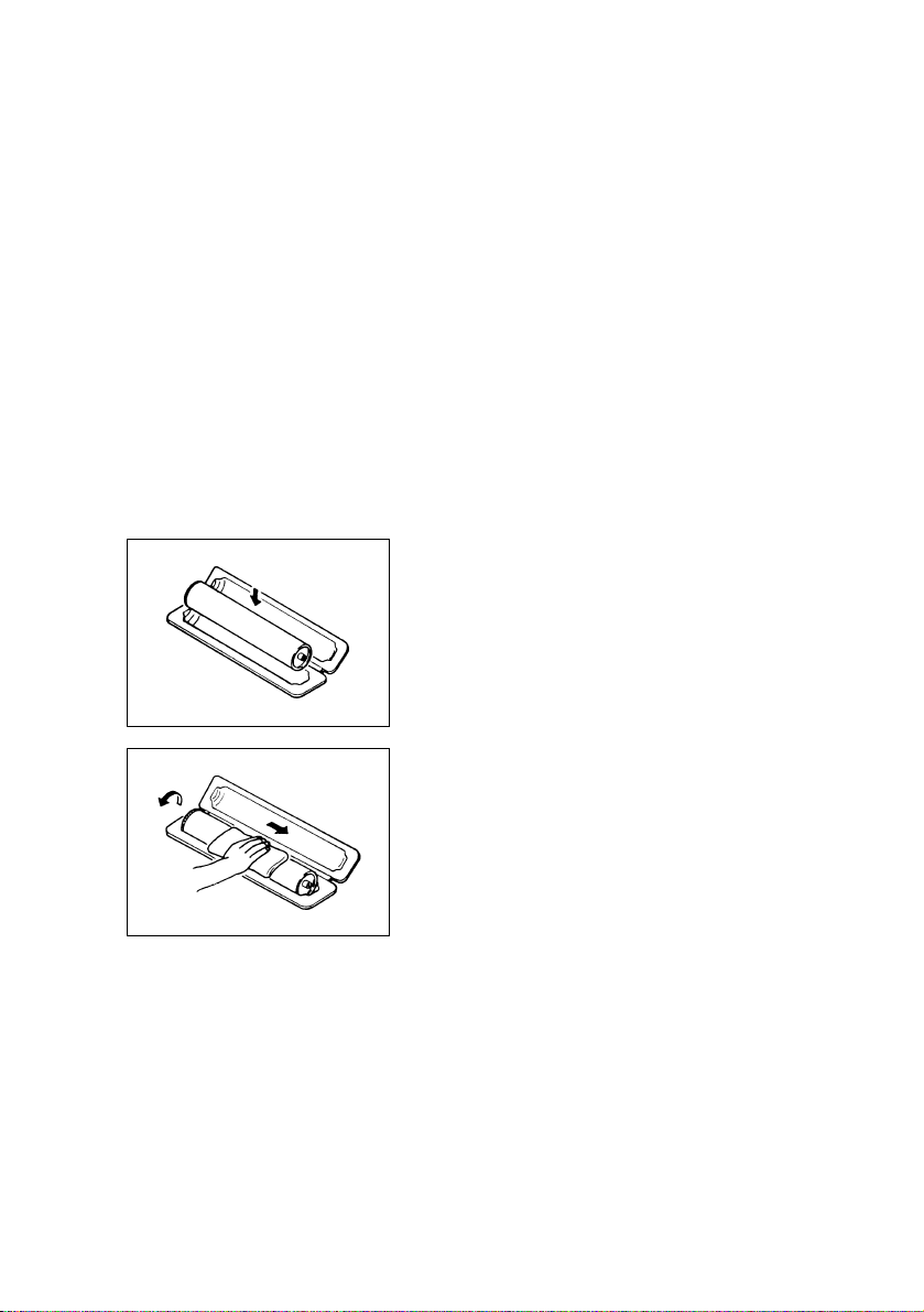
If, however, the surface is contaminated with fingerprints, clean it using the following procedure.
A. Place the PC Drum into one half of its carton.
1076D001
1076D002
B. Gently wipe the residual toner off the surface of the
PC Drum with a dry, Dust-Free Cotton Pad.
• Turn the PC Drum so that the area of its surface on
which the line of toner left by the Cleaning Blade is
present is facing straight up. Wipe the surface in one
continuous movement from the rear edge of the PC
Drum to the front edge and off the surface of the PC
Drum.
• Turn the PC Drum slightly and wipe the newly
exposed surface area with a CLEAN face of the
Dust-Free Cotton Pad. Repeat this procedure until
the entire surface of the PC Drum has been thoroughly cleaned.
At this time, always use a CLEAN face of the dry
✽
Dust-Free Cotton Pad until no toner is evident on the
face of the Pad after wiping.
P-8
Page 10

C. Soak a small amount of either ethyl alcohol or iso-
propyl alcohol into a clean, unused Dust-Free Cotton Pad which has been folded over into quarters.
Now, wipe the surface of the PC Drum in one continuous movement from its rear edge to its front
edge and off its surface one to two times.
Never move the Pad back and forth.
✽
1076D003
D. Using the SAME face of the Pad, repeat the proce-
dure explained in the latter half of step 3 until the
entire surface of the PC Drum has been wiped.
Always OVERLAP the areas when wiping. Two
complete turns of the PC Drum would be appropriate for cleaning.
1076D004
NOTES
• Even when the PC Drum is only locally dirtied, wipe the entire surface.
• Do not expose the PC Drum to direct sunlight. Clean it as quickly as possible even under
interior illumination.
• If dirt remains after cleaning, repeat the entire procedure from the beginning one more
time.
9. Handling of the Imaging Cartridge and Print Unit
Only for Products Employing an Imaging Cartridge and Print Unit.
✽
During Transportation/Storage
• The storage temperature is in the range between –20 °C and +40 °C.
• In summer, avoid leaving the Imaging Cartridge and Print Unit in a car for a long time.
Handling
• Store the Imaging Cartridge and Print Unit in a place that is not exposed to direct sunlight.
Precautionary Information on the PC Drum Inside the Imaging Cartridge and Print Unit.
• Use care not to contaminate the surface of the PC Drum with oil-base solvent, fingerprints, and other foreign matter.
• Do not scratch the surface of the PC Drum.
• Do not attempt to wipe clean the surface of the PC Drum.
P-9
Page 11

Page 12

CONTENTS
1. SAFETY PRECAUTIONS FOR INSPECTION AND SERVICE .......................P-1
1-1. Warning ....................................................................................................P-1
1-2. Caution .....................................................................................................P-3
1-3. Used Batteries Precautions ......................................................................P-5
1-4. Other Precautions ....................................................................................P-6
1-5. Precautions for Service ............................................................................P-6
GENERAL
1. OVERVIEW AND SPECIFICATIONS ..............................................................M-1
1-1. Difference between functions available on different models ....................M-1
1-2. Scan to E-mail ..........................................................................................M-2
1-3. Scan to Server (FTP) ...............................................................................M-3
1-4. Scan to PC (FTP) .....................................................................................M-5
1-5. Scan to HDD ............................................................................................M-6
1-6. Scan to PC (SMTP) ..................................................................................M-7
1-7. Internet Fax ..............................................................................................M-9
1-8. IP Address Fax (LAN-FAX) ......................................................................M-11
1-9. IP Scanner ...............................................................................................M-12
1-10.Distribution of Fax Documents .................................................................M-14
1-11.Direct Fax Transmission ..........................................................................M-15
1-12.PageScope Light ......................................................................................M-17
1-13.Overview of Attached Utilities ..................................................................M-18
(1) “Network FAX” Operating Environment (Reference) .......................M-18
2. RESTRICTIONS AND PRECAUTIONS FOR USING NETWORK A
PPLICATIONS .................................................................................................M-19
2-1. Precautions when using Network Applications ........................................M-19
2-2. Functions that cannot use Network Applications .....................................M-19
(1) Fax functions that can not be used. .................................................M-19
(2) Fax functions that can be used. .......................................................M-19
(3) Precautions for using IP Scanner ....................................................M-20
(4) Using a modem or terminal adapter .................................................M-20
3. FUNCTIONAL OVERVIEW OF CARDS USED ...............................................M-21
3-1. CLAN Card ...............................................................................................M-21
(1) Overview ..........................................................................................M-21
(2) Functions .........................................................................................M-21
(3) LED Indicators .................................................................................M-21
(4) Block Diagram ..................................................................................M-22
Page 13

DIS/REASSEMBLY, ADJUSTMENT
1. EQUIPMENT SETUP .......................................................................................D-1
1-1. Connection ...............................................................................................D-1
2. DISASSEMBLY / REASSEMBLY ....................................................................D-2
2-1. Detaching Parts ........................................................................................D-2
(1) Removing the main cover ................................................................D-2
(2) Removing the CLAN Board ..............................................................D-4
(3) Removing Expansion (Printer / Network Scan /
Internet Fax & Network Scan) Board ...............................................D-6
(4) Removing the function expansion hard disk kit ................................D-7
(5) Removing the function expansion hard disk power supply
circuit board D-8
2-2. Confirmation when Reassembling ...........................................................D-9
(1) Confirm operation of the Printer Controller. .....................................D-9
(2) Confirm operation of the Network Scan kit /
Internet Fax & Network Scan kit. .....................................................D-9
DISPLAYS / SETTINGS
1. TOUCH PANEL DISPLAY CONFIRMATION ...................................................S-1
1-1. Printer unit / Network interface card .........................................................S-1
1-2. Network scanner kit / Network interface kit ..............................................S-2
2. SPECIFICATION PARAMETERS ....................................................................S-3
2-1. Required specification parameters for each model ..................................S-3
(1) Explanation of specification parameters ..........................................S-3
(2) Network Specifications List ..............................................................S-5
3. SOFTWARE SWITCHES .................................................................................S-7
3-1. Software switches that can be changed by users (diagram). ...................S-7
3-2. Table of Default Values ............................................................................S-13
3-3. Changing Software Switch Settings .........................................................S-15
(1) Opening the settings screen from Tech. Rep. Mode .......................S-15
(2) Opening the settings screen from Maintenance Mode ....................S-15
(3) Opening the PC printer software switch settings screen .................S-16
3-4. Software Switch Functions .......................................................................S-17
(1) Table of printer / scanner / network function software switches ......S-17
Page 14

TROUBLESHOOTING
1. ALARM DISPLAY .............................................................................................T-1
2. TRANSMISSION RESULTS ERROR CODES ................................................T-2
2-1. Scan to Server (FTP) Transmissions .......................................................T-2
2-2. Scan to PC (FTP) Transmissions .............................................................T-2
2-3. Scan to HDD Transmissions ....................................................................T-3
2-4. URL notification (with Scan to Server (FTP) and
Scan to HDD transmissions) ....................................................................T-3
2-5. Internet Fax Transmissions / Scan to E-mail Transmissions ...................T-3
2-6. Internet Fax Reception .............................................................................T-4
2-7. Scan to PC (SMTP) Transmissions .........................................................T-5
2-8. IP Scanner ...............................................................................................T-6
2-9. Direct Fax Transmission (Gateway transmissions) ..................................T-7
3. TROUBLESHOOTING FUNCTIONS ...............................................................T-8
3-1. Internet fax Transmissions / Scan to E-mail Transmissions ....................T-8
3-2. IP Address Fax Reception .......................................................................T-8
3-3. Internet Fax Reception .............................................................................T-9
3-4. Distribution of Fax Documents .................................................................T-10
3-5. Scan to PC (SMTP) Transmission ...........................................................T-11
3-6. IP Scanner ...............................................................................................T-11
3-7. Direct Fax Transmission (Gateway transmission) ....................................T-14
3-8. PageScope Light ......................................................................................T-15
3-9. Other (Network Functions) .......................................................................T-16
3-10.Reference: “Network FAX” .......................................................................T-16
(1) “Network FAX” Fax Transmission ....................................................T-16
(2) “Network FAX” .................................................................................T-18
Page 15

Page 16

GENERAL
Page 17

Page 18
1. Overview and Specifications
• The following is an overview of the functions of network scanners and network interfaces:
• For details and requirements, referred to the “electronic manual” in the manual.
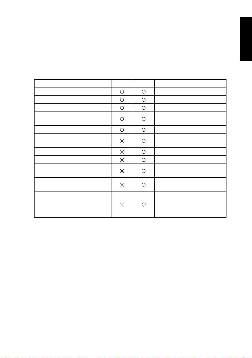
1-1. Difference between functions available on different models
• Depending on model, the functions that can be used differ, and are as follows.
SU-2: Network Scan Kit
SU-3: Internet Fax & Network Scan Kit
Function Name SU-2 SU-3 Remarks
Scan to E-Mail
Scan to Server (FTP)
Scan to PC (FTP)
Scan to HDD
PageScope Light
Scan to PC (SMTP)
Internet fax
IP Address Fax
IP Scanner
Transmission from fax document
Direct fax
The function expansion hard
disk kit is required
Uses IP Scanner /Image
Receiver
Uses IP Scanner /Image
Receiver
When the device is Di2010f/
Di2510f/Di3010f/Di3510f
When the device is Di2010f/
Di2510f/Di3010f/Di3510f
Uses Network Fax transmission
(EX Lite Edition)
M-1
Page 19
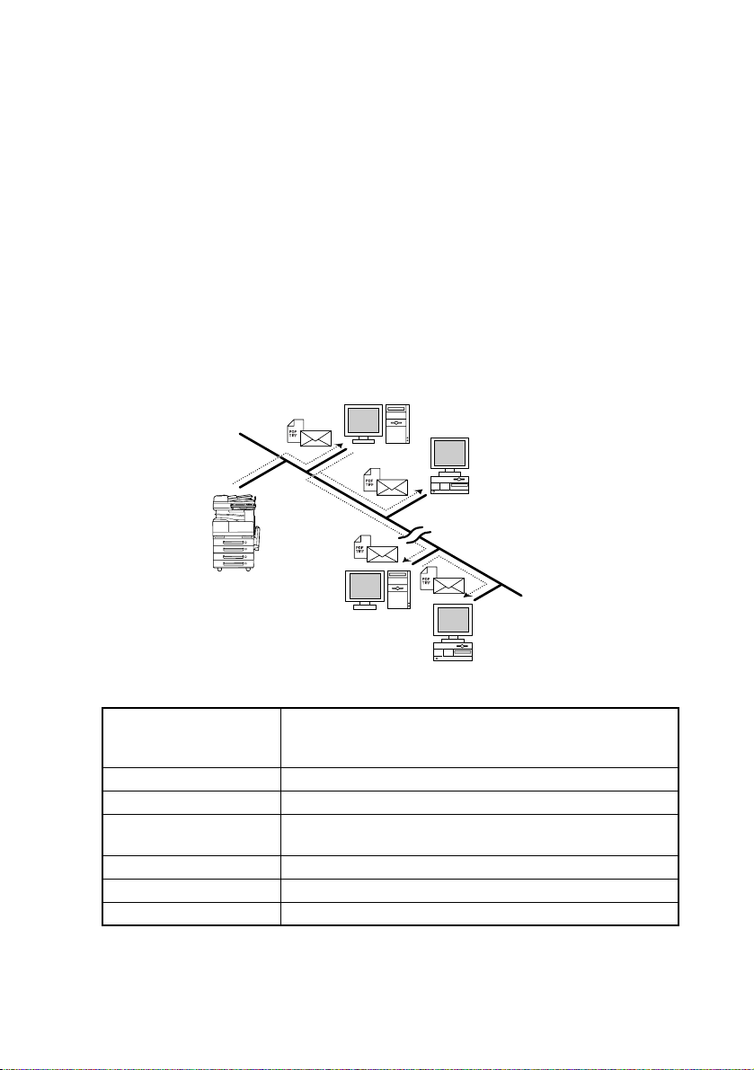
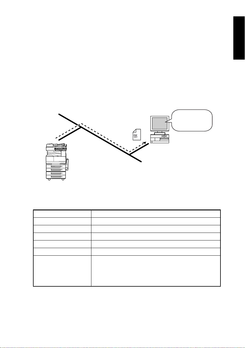
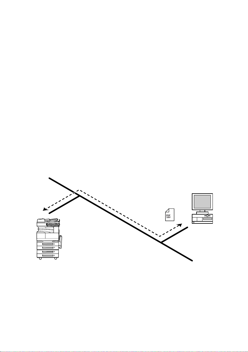
1-2. Scan to E-mail
Attaches the scanned document image data to e-mail, and transmits it to a PC.
Similar to when sending an Internet fax, a paper document can be easily sent via e-mail at
the push of a button.
• The document to be transmitted is attached to MIME format e-mail as either a TIFF-F format or PDF format image file, and then transmitted. In order to view the image that has
been received by the PC, e-mail software that supports the MIME format, and software
that can display either TIFF-F or PDF format image files needs to be installed.
• TIFF-F format images can be viewed using the TIFF Viewer, installed as standard on
Windows.
• PDF format images can be viewed using Acrobat Reader, included as a utility.
• A network environment that includes a mail server is required.
• The device needs to be connected to the LAN, and configured as part of the network.
STEP 1: Indicate transmission to a user PC in the same way as transmitting a fax.
STEP 2: Store the scanned image on the mail server.
STEP 3: Use e-mail software to import the scanned image that is on the mail server.
Mail server
Client computer
Intranet
Internet
Mail server
Specifications
Communications protocol
Transmitted document size A4, B4, A3
Resolution 200 × 100dpi, 200 × 200dpi, 400 × 400dpi, 600 × 600dpi
Data format
Coding method MH, MMR
Compatible circuits Ethernet LAN (100BASE-TX, 10BASE-T connection)
Destination registration Registered PC mail addresses: Maximum 540
E-mail transmission: SMTP (IETF RFC2821 and RFC2822)
procedure
TCP/IP transmission
E-mail format: MIME
Attachment format: TIFF-F, PDF
Client computer
M-2
Page 20

1-3. Scan to Server (FTP)
• Scan data can be uploaded as TIFF or PDF files to a specified directory on an FTP
server.
• In order to view the image that has been received by the PC, software that can display
either TIFF-F or PDF format image files needs to be installed.
• TIFF-F format images can be viewed using the TIFF Viewer, installed as standard on
Windows.
• PDF format images can be viewed using Acrobat Reader, included as a utility.
• A network environment that includes an FTP server is required.
• An FTP server on the Internet can be accessed through a proxy server.
• A maximum of five FTP servers can be registered, and a maximum of five directories can
be set up on each FTP server.
• The device needs to be connected to the LAN, and configured as part of the network.
FTP server
Intranet
Internet
M-3
Page 21
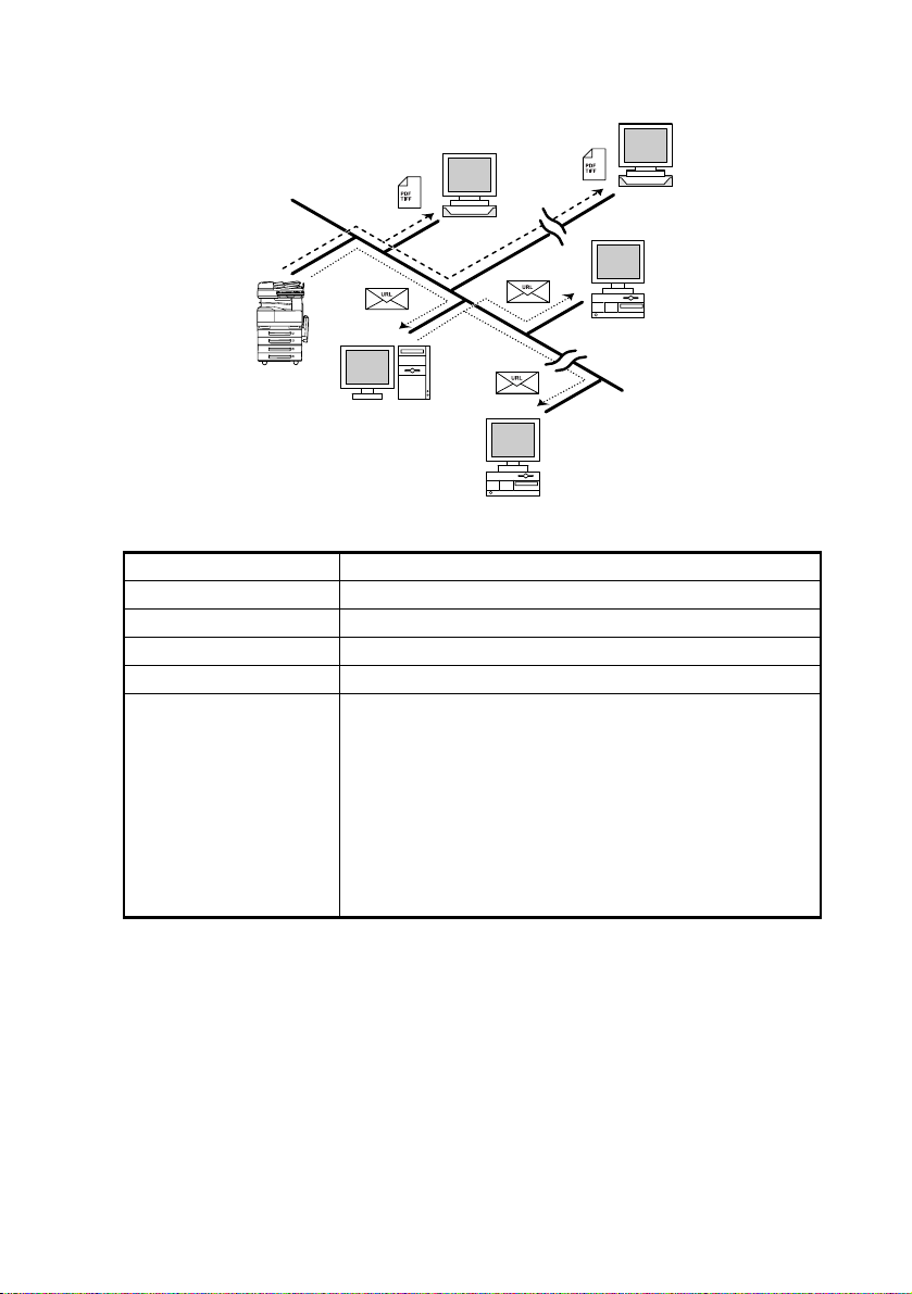
• With the “URL Report” function, a notification of the URL where the scan data is saved
can be sent by e-mail. (If the “URL Report” function is used, a mail server is required.)
FTP server
Internet
Intranet
Internet
Mail server
Client computer
Specifications
Communications protocol FTP, TCP/IP transmission
Resolution 200 × 100dpi, 200 × 200dpi, 400 × 400dpi, 600 × 600dpi
Data format TIFF, PDF
Coding method MH, MMR
Compatible circuits Ethernet LAN (100BASE-TX, 10BASE-T connection)
When registering one-touch keys, select the destination FTP
server and the directory. The FTP server and directory must
have been registered in advance using the network settings
screen.
Destination registration
A maximum of five FTP servers can be registered, and a
maximum of five directories can be registered on each FTP
server.
If all directories will be registered on the same FTP server,
then a maximum of 25 directories can be registered on that
single server.
FTP server
Client computer
M-4
Page 22
1-4. Scan to PC (FTP)
• Scan data can be sent as TIFF or PDF files to client computers using FTP.
• In order to view the image that has been received by the PC, software that can display
either TIFF-F or PDF format image files needs to be installed.
• TIFF-F format images can be viewed using the TIFF Viewer, installed as standard on
Windows.
• PDF format images can be viewed using Acrobat Reader, included as a utility.
• The FTP server application must be running on the client computers.
• The forwarding destination on the client computer is the root folder specified with the FTP
server application. This setting cannot be specified from the copier's control panel or
from PageScope Light.
• The device needs to be connected to the LAN, and configured as part of the network.
FTP Server
application
Client computer
Intranet
Specifications
Communications protocol FTP, TCP/IP transmission
Resolution 200 × 100dpi, 200 × 200dpi, 400 × 400dpi, 600 × 600dpi
Data format TIFF, PDF
Coding method MH, MMR
Compatible circuits Ethernet LAN (100BASE-TX, 10BASE-T connection)
Destination registration Register one-touch keys with destination PC IP address.
The FTP server application must be running on the
destination PC.
Remarks
In Scan to PC (FTP) transmission, access to the FTP server
is “anonymous”. Transmission of data to FTP servers that do
not allow anonymous users is not possible.
M-5
Page 23
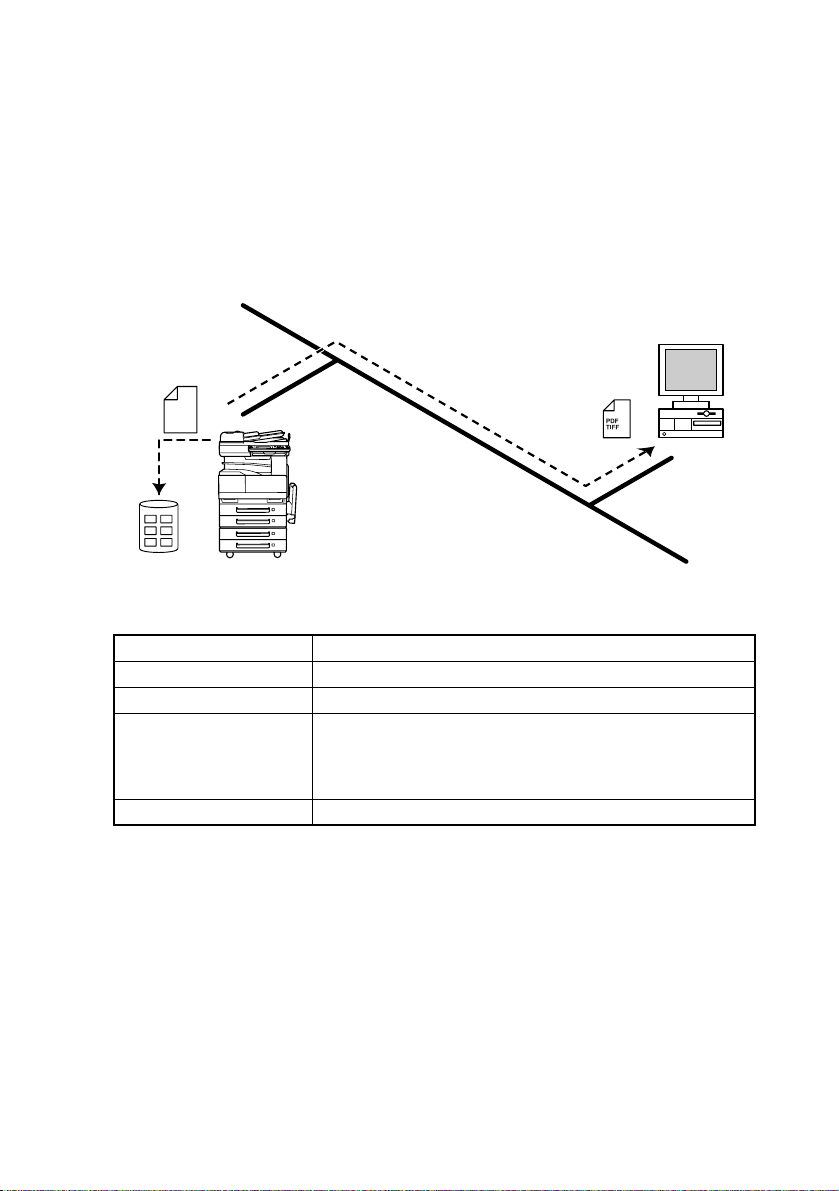
1-5. Scan to HDD
• Scan data is saved on the copier's hard disk as TIFF or PDF files.
• In order to view the image that has been received by the PC, software that can display
either TIFF-F or PDF format image files needs to be installed.
• TIFF-F format images can be viewed using the TIFF Viewer, installed as standard on
Windows.
• PDF format images can be viewed using Acrobat Reader, included as a utility.
• With the “URL Report” function, a notification of the URL where the scan data is saved
can be sent by e-mail. (If the “URL Report” function is used, a mail server is required.)
• The device needs to be connected to the LAN, and configured as part of the network.
Client computer
Scan
data
Intranet
Specifications
Resolution 200 × 100dpi, 200 × 200dpi, 400 × 400dpi, 600 × 600dpi
Data format TIFF, PDF
Coding method MH, MMR
When registering one-touch keys, select the mail box to save
Destination registration
Remarks Loading of data takes place from PageScope Light.
to. A mail box must have been created in advance using
PageScope Light. A maximum of 115 user boxes can be
created.
M-6
Page 24

1-6. Scan to PC (SMTP)
Transmits scanned document images and data to your own PC and stores it in a previously
specified folder.
Even in an environment that does not use mail service, a paper document can be saved as
an electronic file simply by using a one touch key.
To do this, it is necessary to register in advance the IP address or host name of the filing
computer, on the device using the one touch key. On PCs, it is necessary to specify the filing location folder, using the IP Scanner included as a utility. In addition, it is possible to use
the IP scanner configurations in order to use a one touch key to create, and save to a folder.
• The document to be transmitted is transmitted as either a TIFF-F format or PDF format
image file. In order to view the image that has been received by the PC, software that can
display either TIFF-F or PDF format image files needs to be installed.
• TIFF-F format images can be viewed using the TIFF Viewer, installed as standard on
Windows.
• PDF format images can be viewed using Acrobat Reader, included as a utility.
• In order to save the image that has been received by the PC, the enclosed utilities IP
Scanner and Image Receiver are required.
• If there is a DHCP server on the network, this function may not operate correctly since IP
addresses are automatically distributed to each computer. In this case, specify a fixed IP
address for the computer or use IP Scanner.
• The device needs to be connected to the LAN, and configured as part of the network.
STEP 1: Program a one-touch key with the IP address of the computer receiving the data.
STEP 2: Using the same procedure for sending e-mail messages, specify that the data is
STEP 3: The sent scan data is received by the recipient computer.
STEP 4: The IP Scanner application converts the data to a TIFF or PDF file, then saves
to be sent to a computer.
the file in the specified folder.
Intranet
Client computer
M-7
Page 25

Specifications
Communications protocol TCP/IP transmission
Transmitted document size A4, B4, A3
Resolution (dpi) 200 × 100dpi, 200 × 200dpi, 400 × 400dpi, 600 × 600dpi
Data format TIFF-F, PDF
Coding method MH, MMR
Destination registration
Storage folder settings
Register the PC IP address
Maximum 540
Specify a directory on the PC. Below this, directories
specified by the PC may be created for each data item.
M-8
Page 26
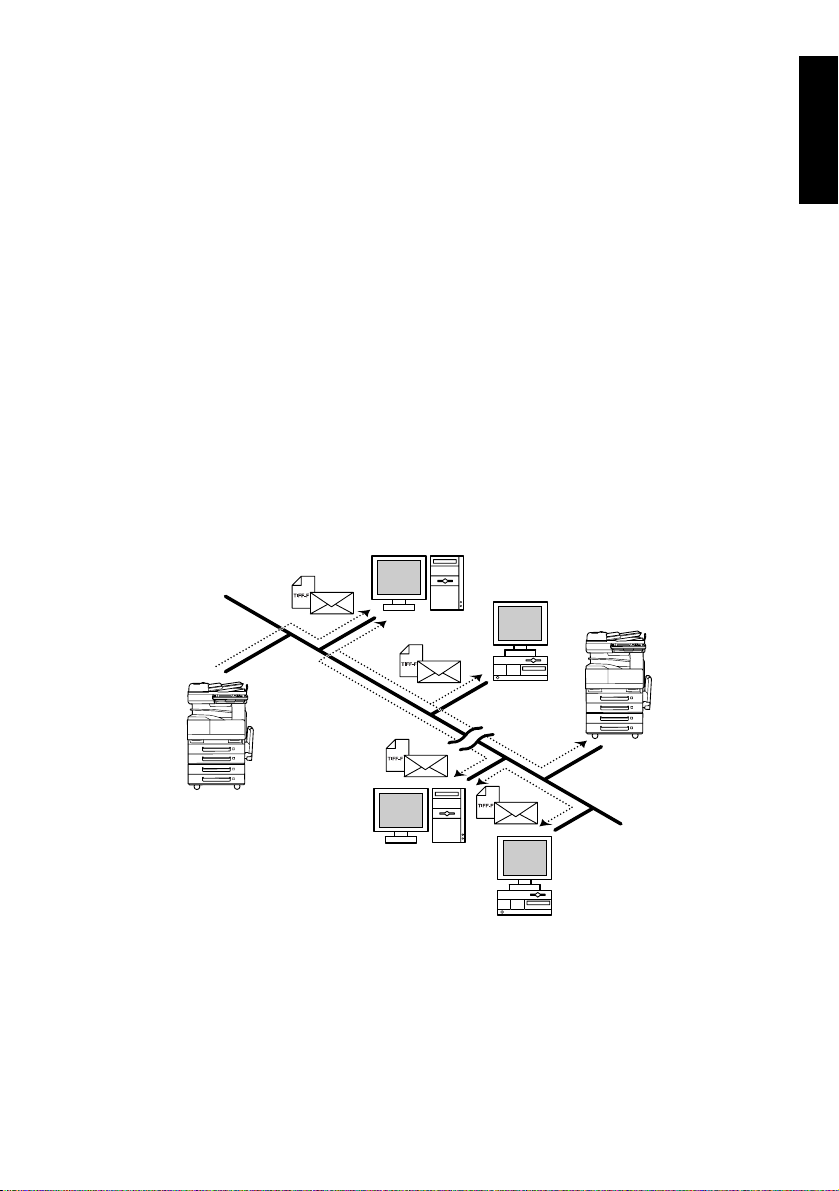
1-7. Internet Fax
Scanned document image data is attached to an e-mail, and is sent to an Internet fax terminal through the Internet or an Intranet.
When sending, specify an e-mail address in the same way as specifying a telephone (fax)
number when sending a regular fax.
If the recipient is already specified with a one-touch key, transmission is easy with the single touch of a button.
• The document to be transmitted is attached to MIME format e-mail as a TIFF-F format
image file, and then transmitted.
• TIFF-F format images can be viewed using the TIFF Viewer, installed as standard on
Windows.
• Internet fax is totally different to a normal fax, which transmits through telephone lines, in
that there is no direct connection with the recipient. There are certain inherent limitations.
• When transmitting faxes using Internet fax, the sender can check reception results from
the recipient.
In addition, the sender can detect the reception capabilities of the recipient machine, and
transmit in accordance with those capabilities (the recipient must also have a machine
that is compatible with the full mode).
• The device needs to be connected to the LAN, and configured as part of the network.
STEP 1: Specify the e-mail address, and from the transmission display, transmit the Inter-
net fax.
STEP 2: Transmit the image to the recipient over an existing e-mail network.
STEP 3: Retrieve mail from the server, and receive the Internet fax.
Mail server
Client computer
Internet
fax terminal
Mail server
M-9
Intranet
Internet
Client computer
Page 27

Specifications
E-mail transmission: SMTP (IETF RFC2821 and RFC2822)
Communications protocol
Transmitted document size A4, B4, A3
Resolution (dpi) 200 × 100dpi, 200 × 200dpi, 400 × 400dpi, 600 × 600dpi
Data format
Coding method MH, MR, MMR
Compatible circuits Ethernet LAN (100BASE-TX, 10BASE-T connection)
TCP/IP transmission
E-mail reception: POP3(IETF RFC1725 and RFC1939)
TCP/IP transmission
E-mail format: MIME
Attachment format: TIFF-F
M-10
Page 28
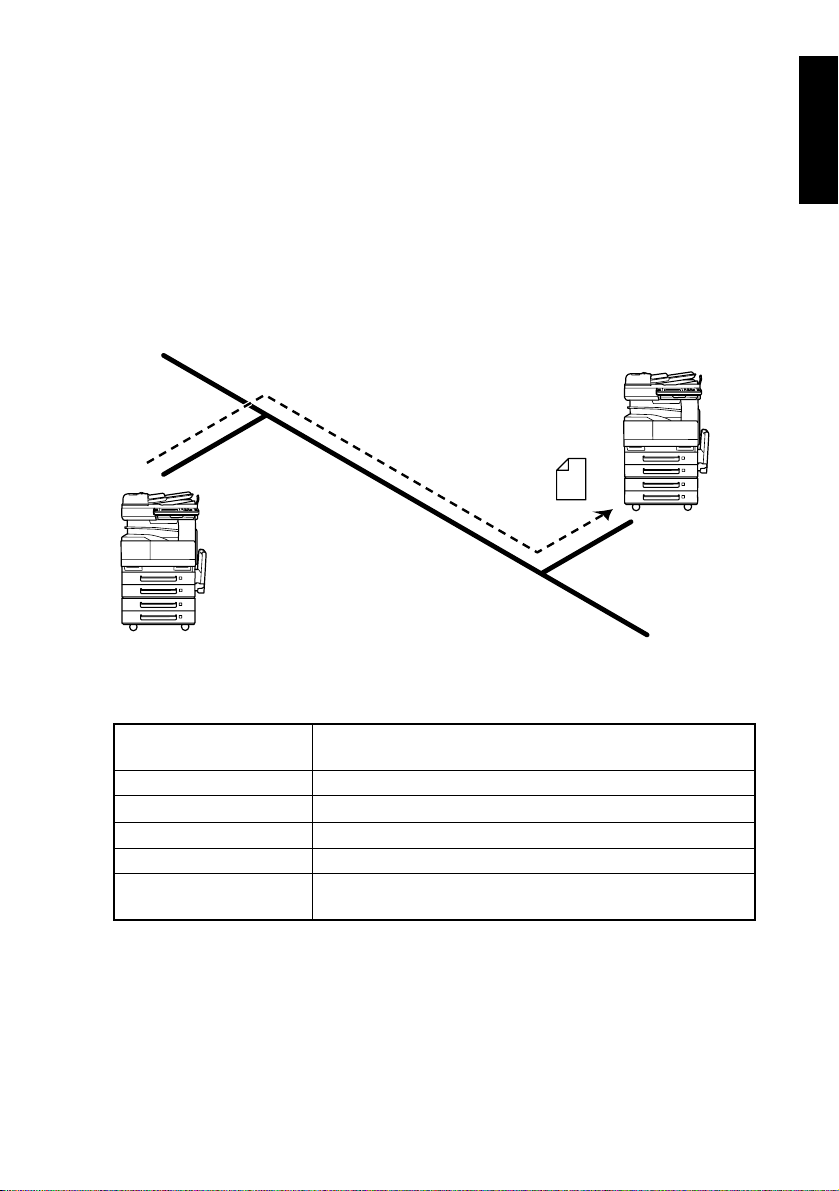
1-8. IP Address Fax (LAN-FAX)
Scan data is sent to a copier of the same type (Internet fax) through the Internet, without
passing though a mail server.
To do this, it is necessary to register in advance the IP address or host name of the recipient, in the device using the one touch key.
• The device needs to be connected to the LAN, and configured as part of the network.
STEP 1: Program a one-touch key with the IP address or host name of the recipient.
STEP 2: Specify the recipient using the one-touch key, and from the transmission display,
STEP 3: Retrieve the fax image (IP address fax transmission).
transmit IP address fax.
Internet fax terminal
(Same model as
this device)
Intranet
Specifications
Communications protocol
Transmitted document size A4, B4, A3
Resolution 200 × 100dpi, 200 × 200dpi, 400 × 400dpi, 600 × 600dpi
Data format TIFF-F
Coding method MH, MR, MMR
Destination registration
E-mail transmission: SMTP (IETF RFC2821 and RFC2822)
TCP/IP transmission
Register the destination IP address
Maximum 540
M-11
Page 29
1-9. IP Scanner
Scanned image data is sent to a client computer, where it is saved in a folder that is created
using the name of the scanner button.
After programming a button (Scan data destination and scan settings) from the client computer when scanning, a paper document can easily be saved as an electronic file with just
the touch of a button in the copier’s touch panel.
• The document to be transmitted is transmitted as either a TIFF-F format or PDF format
image file. In order to view the image that has been received by the PC, software that can
display either TIFF-F or PDF format image files needs to be installed.
• TIFF-F format images can be viewed using the TIFF Viewer, installed as standard on
Windows.
• PDF format images can be viewed using Acrobat Reader, included as a utility.
• In order to view the image that has been received by the PC, the enclosed utilities IP
Scanner and Image Receiver are required.
• This function can be used in a network without a LAN if a crossover cable is used to con-
nect the copier to a client computer. (Network settings are required.)
• The device needs to be connected to the LAN, and configured as part of the network. In
addition, the destination PC also needs to be connected to the LAN, and configured as
part of the network.
STEP 1: From the user’s PC, program a button (recipient of the scan data).
STEP 2: Press the programmed button to send the scan image.
STEP 3: The sent scan image is received by the recipient computer.
STEP 4: The IP Scanner application converts the data to an image file TIFF-F format),
then saves the file in the specified folder.
Client computer
M-12
Page 30

Specifications
Communications protocol TCP/IP transmission
Transmitted document size A4, B4, A3
Resolution (dpi) 200 × 200dpi, 400 × 400dpi, 600 × 600dpi
Data format TIFF-F, PDF
Coding method MH, MMR
Destination registration not required: automatically obtains
Destination registration
Storage folder settings
the OP address from the PC when scanning.
Button registration: A maximum of six scanner buttons on a
copier can be programmed.
Specify a directory on the PC. Below this, directories
specified by the PC may be created for each data item.
M-13
Page 31

1-10. Distribution of Fax Documents
Image data received from a fax machine on a common telephone line can be sent directly
to a computer or attached to an e-mail message.
The fax document can be received at your own computer.
Received fax documents can be classified as “F-Code”, “Reception Port” or “Public Document”, and the distribution destinations for each type of document can be specified.
• By specifying a one-touch key as a forwarding destination, fax documents can be sent as
TIFF or PDF image format files directly to computers, or as a TIFF image file directly as a
MIME e-mail attachment. In order to view the image that has been received by the PC,
software that can display either TIFF-F or PDF format image files needs to be installed.
Additionally, in order to transmit e-mail, MIME compliant e-mail software is required.
• TIFF-F format images can be viewed using the TIFF Viewer, installed as standard on
Windows.
• PDF format images can be viewed using Acrobat Reader, included as a utility.
• F codes are used in various other ways, such as a mailbox or a bulletin board.
When specifying F codes, we recommend managing numbers, such as by to classifying
the data by function, in order to prevent number duplication.
• When forwarding faxes by e-mail, a network environment that includes a mail server is
required.
• The device needs to be connected to the LAN, and configured as part of the network.
STEP 1: Use the Doc. Manage settings to classify and store the fax image.
STEP 2: The fax image is sent to the computer specified as the recipient.
STEP 3: The fax image is received by the recipient computer as an image file.
Facsimile
terminal
Specifications
Registering forwarding
destinations
communications
Facsimile
Telephone
line
Client computer
In account registration for this copier, specify the F-Code or
forwarding destination mail address.
M-14
Mail server
Page 32

1-11. Direct Fax Transmission
A document created in an application, such as word-processing software, can be faxed by
specifying the telephone (fax) number of the recipient, without first printing the document.
An e-mail address or a telephone (fax) number can be specified for the recipient.
• To carry out direct fax transmission, “Network FAX Transmission”, included as a utility is
required. Check the network environment, configure the network, and install “Network
FAX ”.
• In order to perform direct faxing operations using a mail server, the DNS settings must be
specified.
• The result of the completed fax transmission can be checked from the computer.
• The device needs to be connected to the LAN, and configured as part of the network.
STEP 1: Specify the fax number of the destination (specify the recipient after specifying
STEP 2: The image data is transmitted from the client computer or mail server.
STEP 3: The data received by the computer is sent to the specified fax number.
Client computer
printing from the application).
Mail server
Telephone
line
Facsimil e Facsimile
terminalcommunications
M-15
Page 33

Specifications
Sender FAX, E-Mail, iFAX
Transmitted document size A4, B4, A3
Resolution 200 × 200 dpi, 400 × 400 dpi
Coding method
Data exchange FAX data ← Conversion → BMP, TIFF data
Transmission quantity
Broadcast transmission Maximum 1500
Entries in phone book
Phone book search
functions
Management functions
FAX: MH
E-Mail/ iFAX: TIFF
Comments of maximum of approximately 700 single byte
characters can be input.
Per single phone book: Maximum 1000 entries (No limit on
number of phone books)
Search: search for “Paris”, and it searches for all items
containing “Paris”.
Search on Item: specify parameters and search.
Search on Group: select a group name and search.
Document storage: specify storage numbers for each
document box and warnings for transmission.
Nondelivered document management: resend nondelivered
documents
Trash: interim storage of documents discarded from
document boxes.
Headers: Registration of each document’s headers (30).
Creation of tables: Documents, nondelivered documents,
transmitted documents, documents in the trash.
M-16
Page 34

1-12. PageScope Light
PageScope Light is a utility for managing devices supported by the HTTP server integrated
into the printer/scanner controller.
Using a Web browser, PageScope Light can remotely control the printer/scanner controllers on the network.
For Administration
• Setting of fixed number of
device systems
• Understanding of usage
status
Specifications
Communications protocol TCP/IP, HTTP
Data format HTML
Windows 95/98/Me/NT4.0: Internet Explorer 4 or later
Netscape Navigator 4.73 or 7.0
Supported browsers
Windows 2000: Internet Explorer 5 or later
Netscape Navigator 7.0
Windows XP: Internet Explorer 6 or later
Netscape Navigator 7.0
Internet / Intranet
For Users
• Monitoring of usage status
• Display of communications
results
• Confirmation of alarm status
• One-touch key registration
LAN
M-17
Page 35

1-13. Overview of Attached Utilities
Network FAX transmission
IP Scanner
(1) “Network FAX” Operating Environment (Reference)
• For detailed operating restrictions, refer to the “Network FAX” user’s manual. (electronic
manual)
PC Type
CPU Pentium 133 MHz or higher
Memory
Hard disk free space
Supported operating
systems
Operation environment
Software that enables users to send faxes directly from
applications by specifying the telephone (fax) number, without
first printing the document.
IP Scanner functions and one-touch document scanning –
Software that enables users to IP address type functions.
Supported OS: Microsoft Windows 95 (English edition)
Microsoft Windows 98 (English edition)
Microsoft Windows Me (English edition)
Microsoft Windows NT4.0 (English edition)
Microsoft Windows 2000 (English edition)
Microsoft Windows XP (English edition)
PC/AT compatible machines.
(Limited to all officially supported Windows98/ Me/ NT4.0/
2000/ XP versions)
24 MB or more (48 MB recommended)
*IP Scanner: 32 MB or more (64 MB recommended)
64 MB or more (128 MB recommended) for Windows® XP or
Windows® 2000
50 MB or more
(More recommended for document management functions)
Microsoft Windows 98 (English edition)
Microsoft Windows Me (English edition)
Microsoft Windows NT4.0 (English edition)
Microsoft Windows 2000 (English edition)
Microsoft Windows XP (English edition)
A network environment that can be used by this computer or
a mail server.
M-18
Page 36

2. Restrictions and Precautions for using network
Applications
2-1. Precautions when using Network Applications
• Internet faxes and Scan to E-mail transmissions are sent and received with the help of a
mail server; they are not sent directly to the recipient or received directly from the sender.
In addition, as soon as transmission with the server is finished correctly, the transmission
is considered complete.
• If transmission from the mail server to the recipient is not possible for some reason, an email describing the error will be received from the server.
• For some reason, the e-mail describing the error may not be received. If confirmation of
the transmission is required, call the recipient after transmission to confirm reception.
• Since the privacy of transmissions through the Internet or an intranet is limited, we recommend sending important documents directly to the recipient through a common telephone line.
• Telephones on a LAN cannot be used.
• It may take some time for a transmission to be sent due to Internet/ intranet traffic.
• Depending on the mail servers, it may not be possible to send documents with a large
number of pages or a large amount of image data.
2-2. Functions that cannot use Network Applications
(1) Fax functions that can not be used.
• The following fax functions can be used by regular fax machines over a common telephone line, but can not be used with network applications.
Batch transmission Bulletin board registration Polling transmission
On-hook Real-time transmission
Confidential box Password transmission * Remote copying *
*: These items are specified on the panel, but are not functional.
Remote retrieval of bulletin
board
(2) Fax functions that can be used.
• The following fax functions can be used with network applications.
Image quality specification 2 in 1 Destination insert
Forward the received
Density specification 2-sided transmission
Non-reduction mode TX marker stamp (optional) Priority transmission
Scan area specification TSI Timer transmission
Time stamp
• Precautions on Mail Delivery of Fax Documents
facsimile documents
(Document Management)
M-19
Page 37

(3) Precautions for using IP Scanner
1. Using a dial-up router
• When using IP Scanner, ensure that the IP address of the main device is correctly specified.
Particular care is needed when using IP scanner on a network in which an a dial-up
router is used.
• If an incorrect IP address is specified in an environment where a dialup router is used,
the dial-up router may unnecessarily be dialed up.
In addition, depending on the network environment of the computer, the dial-up router
may be unnecessarily dialed up, regardless of whether the correct IP address was specified.
(4) Using a modem or terminal adapter
• If a computer with a built-in modem (or a computer connected to terminal adapter) is
used, they may be used to dial up.
If this occurs, select either “Never dial a connection” or “Dial whenever a network connection is not present” in the “Dial-up settings” group box on the Connections tab of the Internet Properties dialog box. For details, refer to the instruction manual for the operating
system.
M-20
Page 38

3. Functional Overview of Cards Used
Cards that can be used in the Network Scan / Internet Fax & Network Scan / Printer have
the following capabilities.
Card name Functional overview
CLAN card By connecting to the MFB3 card, network functions can be used.
Printer card
Network scan card
Internet Fax & Network
Scan card
3-1. CLAN Card
(1) Overview
• This circuit board comprises a network LAN interface and an extended PCI interface,
made up of a USB1.1b interface and PCI bus interface, in order that the copier can be
used as a PC printer.
• Network specifications (Ethernet): 10Base-T/100Base-TX
• Communications protocols: TCP/IP, SMTP, POP3, MIME, HTTP
• Connection method: Connection to CN7 on the MFB3 circuit board.
(2) Functions
1. USB1.1b interface
• The USB connector is used so the copier can be used as a PC printer.
2. Network LAN interface
• The network connector enables the copier to be used as a network scanner and network
printer.
3. Extended PCI interface
• Fitted with a PCI bus interface connector (specialized connector: 100pin) as a future
extended interface.
By connecting to the MFB3 card, printer functions can be used.
Pi3505e: 32MB, Pi3505e/PS:128MB capacity.
By connecting to the MFB3 card, network scanner functions can
be used. 128MB capacity.
By connecting to the MFB3 card, Internet Fax and Network Scan
functions can be used. 128MB capacity.
(3) LED Indicators
LED Condition Meaning
Lit The LAN is connected correctly
Data may be sent or received.
Green
Red
Off
Flashing Data is being sent or received.
Lit Operating at 100Mbps
Off Operating at 10Mbps
The copier has not been turned on.
The LAN is not connected correctly.
M-21
Page 39

(4) Block Diagram
MFB3 board
interface connector
100 pin
Address bus
Data bus
Europe
PCI bus
USB
controller
USB1.1b
LAN
controller
PCI bus interface for future expansion
Specialized 100 pin connector
Plus
trans-
former
USB connector
4 pin
Series B
LAN connector
8 pin
100base-T
M-22
Page 40

DIS/REASSEMBLY,
ADJUSTMENT
Page 41

Page 42

1. Equipment Setup
1-1. Connection
• Connection with phone lines and other devices is as follows.
Standard device
1
2
No. Name Connected to: Remarks
1 TEL PORT1 External telephone Standard
2 LINE PORT1 Telephone line (port 1) Standard
3 LINE PORT2 Telephone line (port 2) Option G3 multiport required
4 DC-IN
6 HAND SET Handset Option
7 LAN LAN cable connection Option
8 USB Printer connection Option
Optional power
connector
Left rear
Optional device
3
4
5
6
Option
7
4384D501AA
Cannot be used when FAX/
TEL switcher and handset
installed
FAX/TEL switcher and handset
required5 TEL External telephone Option
External interface kit required
8
Rear
D-1
Page 43

2. Disassembly / Reassembly
When carrying out disassembly and reassembly, refer to the copier and controller service
manuals.
NOTE
• Before commencing, confirm that the storage memory capacity is at 0%.
• If the memory storage capacity is not at 0%, either print out, or delete any data in the
memory.
2-1. Detaching Parts
When detaching parts from network scanners, network interfaces, or printers, follow the
procedure as follows:
(1) Removing the main cover
1. Remove the upper rear cover (3 screws).
NOTE
• When removing the cover, push in the ADF angledetecting lever.
• When fixing the cover, push the angle-detecting
sensor lever through the hole in the upper rear
4599U008AB
cover.
Cable connector
Cable clamp
I/F CLAN board
cover
4514U002AB
2. Remove the two cable connectors.
3. Removed the two cables from the cable of the
clamps.
4. Remove the interface CLAN board cover (6
screws).
D-2
Page 44

4599U009AB
4599U040AA
4599U036AA
5. Remove the rear cover (13 screws).
(When removing, lift the cover slightly.)
NOTE
When fixing the cover, use gold colored screws in the
six upper locations.
6. Remove the reinforcing plate (4 screws).
NOTE
Do not pinch the hard disk flat cable or power relay
harness.
7. Remove the connector attachment plate (1
screw).
4514U003AA
D-3
Page 45

(2) Removing the CLAN Board
CN4
4599U035AA
CN5
4599U034AA
1. When the function expansion hard disk kit is
removed, disconnect CN4 and CN5 from the
CLAN board.
D-4
Page 46

2. Remove the three screws.
The screws in ➁ can be accessed by opening the document cover, and reaching
✽
between the scanner.
The screws in ➂ also hold the CLAN finger.
Use a short screwdriver for screws in ➁ and ➂.
3. Remove the CLAN board.
CLAN circuit board
4514U007AB
➂
➀
➁
CLAN finger
C4514U008AA
When affixing the CLAN board, prior to this, make
✽
sure that the OPE cable is not covered by the connector for the CLAN circuit board.
4514U005AB
When affixing the CLAN board, push the two parts
✽
indicated with arrows and confirm that the connector is properly inserted (do not touch any soldered
areas).
4514U007AA
D-5
Page 47

(3) Removing Expansion (Printer / Network Scan / Internet Fax & Network Scan)
Board
CN3
Expansion 1 slot (CN4)
Expansion 2 slot (CN5)
4514U010AB
1. With the Di3510f, Di3010f, Di2510f or Di2010f,
disconnect the Ni-MH battery cable from CN3 on
the MFB3 circuit board (in order to prevent damage to the memory IC).
NOTE
Disconnect the Ni-MH battery cable from CN3 on the
MFB3 circuit board to stop power from being supplied to the expansion memory from the Ni-MH battery.
2. Remove the Printer Memory circuit board from
the expansion slot 1 (CN4) on the MFB3 circuit
board.
3. Remove the Network Scan circuit board and the
Internet Fax & Network Scan circuit board from
the expansion slot 2 (CN5) on the MFB3 circuit
board.
NOTE
• Do not touch the terminals of the Printer circuit
board with your bare hands.
• Check the installation direction (location of the
notch), and then firmly insert the circuit board until
it snaps into place.
With the Di3510f, Di3010f, Di2510f or Di2010f,
✽
reconnect the Ni-MH battery cable to CN3 on the
MFB3 circuit board.
NOTE
If the cable is not reconnected, there will be no
backup power in case of a power failure. Therefore,
be sure to reconnect the battery cable.
D-6
Page 48

(4) Removing the function expansion hard disk kit
1. Remove the upper rear cover, the rear cover, the
interface CLAN circuit board cover, the reinforcing plate, and the connector plate.
2. Remove the connector from CN4 on the CLAN
circuit board.
4599U035AA
3. Remove the unit's relay from the wire harness.
NOTE
Harness types differ between the copier and the harness.
4599U041AA
4. Remove the mechanism circuit board cover (5
screws).
NOTE
Do not pinch the harness on the right of the mechanism circuit board cover.
4599U039AA
4599U023AC
5. Remove the flat cable from the hard disk.
When connecting the flat cable to the hard disk,
✽
connect with the ▼ as standard.
NOTE
• Connect so that the yellow wire on the flat cable is
at the left of the hard disk connector. (Up)
• The 4 terminals on the left of the hard disk are to
remain unused.
D-7
Page 49

6. Remove the hard disk from the mechanism circuit
board (4 screws).
When affixing the hard disk to the mechanism cir-
✽
cuit board, tighten until the bush at the back of the
mechanism circuit board cover is as in the figure.
4599U022AB
4599U038AB
(5) Removing the function expansion hard disk power supply circuit board
1. Remove the lower cover (4 screws).
NOTE
When fixing the hard disk, insert toothed washers
into the top right of the lower rear cover.
4348U018AC
2. Remove CN1 and CN2 from the connectors on
the power supply circuit board.
CN1
CN2
4599U013AB
4599U018AA
D-8
Page 50

3. Remove the power supply circuit board (4
screws).
4599U012AA
2-2. Confirmation when Reassembling
(1) Confirm operation of the Printer Controller.
Press <Utilities> on the operations panel, and confirm that “Printer Settings” is displayed at
the bottom left of the touch panel utility screen.
(2) Confirm operation of the Network Scan kit / Internet Fax & Network Scan kit.
Press <Utilities> on the operations panel, press “Management Administration”, “Manage-
ment Administration 2”, and “Network Settings”, and confirm that DNS settings is displayed.
When configuring network settings, it is necessary to restart the printer.
✽
D-9
Page 51

D-10
Page 52

DISPLAYS / SETTINGS
Page 53

Page 54

1. Touch Panel Display Confirmation
• Check the touch panel display settings as confirmation after service of this option.
• Where it is not displayed, repair the problem by refering to troubleshooting.
1-1. Printer unit / Network interface card
How to display confirmation of [Printer Settings].
1. Press the [Utility] key, and the Utility screen is displayed.
[Printer setting]
is displayed.
C4514P735CA
S-1
Page 55

1-2. Network scanner kit / Network interface kit
How to display confirmation of “Printer Settings”.
1. Press the [Utility] key, and the Utility screen is displayed.
2. Touch [Admin. Management].
3. Input the Administrator code, and press [OK].
4. Touch [Admin 2].
5. Check that the [Network Set] key is displayed.
[Network Set] is
Displayed.
C4514P704CA
6. Touch [Network Set], and check that [DNS Settings] is displayed.
[DNS Settings] are
displayed.
C4514P705CA
S-2
Page 56

2. Specification Parameters
• Network scanners and network interfaces have many specification and registration
parameters. These can all be specified by the user.
• Network specifications are to be carried out by the user's network administrator.
• For details on specification parameters, refer to the user manual.
2-1. Required specification parameters for each model
(1) Explanation of specification parameters
Specification Parameters Explanation
Basic Specifications
DHCP Specify whether an IP address is automatically assigned from a DHCP server, or
IP address Specify this copier’s IP address.
Subnet Mask Specify the subnet mask for the network to be connected.
Gateway Specify the default gateway address for the network to be connected.
Device Domain Name Specify this copier's domain name.
Network Port Settings Specify the network port transmission speed.
DNS Settings
DNS Settings Specify whether to use DNS (Domain Name System) functions.
Host Name Specify the DNS server host name.
Domain Name Specify the DNS server domain name.
DNS Server Address Specify the DNS server IP address.
Device Name
Device Name This device name is used as a part of the filename in Scan to E-mail transmission, Scan
SMTP settings <Transmission settings for Scan to E-mail and Internet fax transmissions (this is also
SMTP Server Address Specify the IP address or host name of the SMTP server.
E-mail Address Specify this copier's e-mail address.
POP3 Settings <Reception settings for Internet faxing>
POP3 Server Address Specify the POP3 server's IP address or host name.
POP3 User Name Specify the POP3 server’s login name (account name).
POP3 Password Specify the password to log into the POP3 server.
Automatic Mail Check Specify the interval to connect to the POP3 server and check for mail (Internet fax).
Specify Priority Compression
Level (mail mode)
Transmission Size
(upper limit)
Transmission Quality (limit) Specify the upper limit for transmission quality.
Encoding Format Specify the encoding format for transmitted scan data.
Specify Priority Compression
Level (scanner mode)
File Format Specify the file format for when transmitting scan data.
Encoding Format Specified the encoding format for when transmitting scan data.
Specifications for sending and receiving scans
Result Notification Specify whether to notify of reception of Internet faxes.
Print Received Document
Headers
whether a static IP address is specified.
Only specify when “specify IP” is selected for DHCP.
• Only specify when “specify IP” is selected for DHCP.
• Only specify when “specify IP” is selected for DHCP.
Specification required when sending a direct fax through a mail server.
• Only specify when “Use” is selected for DNS settings.
• Only specify when “Use” is selected for DNS settings.
• Only specify when “Use” is selected for DNS settings.
to Server transmission, Scan to PC transmission, Scan to HDD transmission, and
Internet fax transmission. In addition, it is also used in the Subject field of Internet fax
transmissions and scan to e-mail transmissions.
used in Scan to FTP and Scan to HDD URL acknowledgements)>
• The Host Name can only be specified when “Use” is selected for DNS settings.
<Specify the upper transmission size limit, upper transmission quality limit, and
encoding format for when transmitting internet fax and IP address fax.>
Specify the upper size limit for documents.
< Specify the file format and encoding format for when transmitting Scan to E-mail,
Scan to Server, Scan to PC (FTP), Scan to PC (SMTP), and Scan to HDD.
When printing received Internet faxes, specify whether to print the mail headers.
S-3
Page 57

Specification Parameters Explanation
Insert Text in Transmitted
Document
Gateway Transmission Specify whether there are direct fax transmission functions.
Subject Registration Register the subject when transmitting Internet faxes and Scan to E-mail transmissions.
Binary Split Settings Specify split settings for Internet fax, Scan to E-mail transmission
FTP Site Registration <Specification required when using Scan to Server (FTP)>
Proxy Specification <Specification required when connecting to an FTP server through a proxy ser ver. This
Proxy Server Specify the proxy server's IP address or host name.
Port Number Specify the proxy server's port number.
FTP Server Timeout Specify the FTP server connection timeout interval.
Frame Type Specification <Specify the frame type for when using PC printer functions, for when connected to a
Ping Used to check that the network (LAN connection) is correctly connected.
Specify whether to include an explanation that a file is attached in Internet faxes and
Scan to E-mail.
can only be specified in PageScope Light administrator mode>
NetWare server>
S-4
Page 58

(2) Network Specifications List
• This lists the required specification parameters for when using network interface functions
Function
Scan to
Scan to
Scan to
Server
E-mail
Specification
Parameters
Basic Specifications
DHCP
IP address
Subnet Mask
Default Gateway
Device Domain
Name
Network Port
Settings
DNS Settings
DNS Settings ——
Host Name ——
Domain Name ——
DNS Server
Address
Device Name
Device Name ————
SMTP Specifications
SMTP Server
Address
Por t Nu mbe r
E-mail Address
(FTP)
—————————
*1
*1
*1
Scan to
PC
(FTP)
PC
(SMTP)
——
——
——
Scan to
HDD
*1
*1
*1
IP
Internet
Scanner
Faxi ng
——
———
———
———
IP
address
Faxi ng
Delivery of
a document
received by
fax
Network
FAX
: Essential items : Available items : Required depending on environment
—: Unnecessary
S-5
Page 59

Function
Scan to
Scan to
Scan to
Server
E-mail
Specification
Parameters
POP3 Settings
POP3 Server
Address
Por t Nu mbe r
POP3 User
Name
POP3 Password
Automatic Mail
Check
Priority Compression Level
Mail Mode
Scanner Mode
Specifications for sending and receiving scans
Result Notifica-
tion
Print Received
Document
Headers
Insert Text in
Transmitted
Document
Gateway
Transmission
Subject
Registration
Split Settings
FTP Site Registration
FTP Site
Registration
Ping
Used to check that the network (LAN connection) is correctly connected.
*An SMTP server or POP3 server can be specified and a ping transmitted. In addition, an arbitrary IP address specified,
and a ping transmitted.
Frame Type Specification
Specify the frame type for when using PC printer functions, for when connected to a NetWare server.
PageScope Light Administrator Mode: [Network] > [FTP Server] > [FTP Specifications]
Proxy Server
Address
Proxy Port
Number
FTP Server
Timeout
(FTP)
—————— ———
—————— ———
—————— ———
—————— ———
—————— ———
—————— —
—————— ———
—————— ———
————— — —
—————————
————— ———
————— ———
— ————————
— ————————
— ————————
— ————————
PC
(FTP)
Scan to
PC
(SMTP)
Scan to
HDD
IP Scan-
Internet
ner
Faxi ng
—————
IP
address
Faxi ng
Delivery of
a document
received by
fax
Network
FAX
*1: When using the URL notification functions, mail transmission (SMTP) settings must be
configured.
S-6
Page 60

3. Software Switches
3-1. Software switches that can be changed by users (diagram).
Utility
User Set
User's Choice
Memory Recall (ON/OFF)
1/6
Mixed Original Detection (ON/OFF)
Language Selected for LCD (Japanese/English/French/ )
2/6
Original → Copy Default (1-Sided → 2-Sided/
2-Sided → 2-Sided/1-Sided → 1-Sided)
Auto Paper/Auto Size (Auto Paper/Auto Size/Manual)
Drawer Priority (Legal)
Special Paper (Normal/Nor for 2 Sided/Recycle/Special)
Multiple-in-1 and Booklet Copy Zoom (ON/OFF)
Energy Save Mode (1 to 240 Minutes: 15 Minutes)
3/6
Sleep Mode Setting (1 to 240 Minutes: 1 Minutes)
LCD Back-light OFF (1 to 240 Minutes)
Auto Panel Reset (No Reset/30 Sec./1 to 240 Minutes)
Plug-in Counter, ID key Reset (ON/OFF)
12
4/6
4-in-1 Copy Order ( / )
Density Priority (Auto/Manual)
(Text/Photo/Text+Photo)
Default Copy Output Levels (Lighter/Normal/Darker)
Printing Density (-2/-1/0/1/2)
Output Priority
(Non-Sort/Sort/Group/Corner Staple/2-Point Staple/Hole Punch)
(Corner Staple/2-Point Staple/Hole Punch are options)
Intelligent Sorting (ON/OFF)
5/6
Output Tray (Optional)
Received prints: (FAX/Network)
Copy and print: (PC print/Copy)
"Small" Originals (ON/OFF)
Scanner Dry
6/6
Priority Screen
Default Device Priority (Copy/FAX/Scanner/Auto)
Priority FAX Screen
(One-Touch/Search/10-key Dialing/Index)
Priority Device (Copier/Printer)
Density (ADF only) (mode 1/ mode 2)
13
34
24
MODE 400 Bit 7
MODE 400 Bit 6
MODE 401 Bit 7 - 4
MODE 402 Bit 7 - 5
MODE 402 Bit 4, 3
MODE 408 Bit 7 - 4
MODE 403 Bit 7
MODE 405 Bit 7 - 0
MODE 406 Bit 7 - 0
MODE 407 Bit 7 - 0
MODE 404 Bit 7 - 0
MODE 403 Bit 0
MODE 409 Bit 7 - 6
MODE 409 Bit 5
MODE 409 Bit 4 - 1
MODE 410 Bit 7,6,
3 - 0
MODE 411 Bit 7,2 - 0
MODE 412 Bit 7 - 4
MODE 412 Bit 3
MODE 413 Bit 7 - 0
MODE 419 Bit 7 - 0
MODE 424 Bit 3
MODE 402 Bit 1,0
MODE 018 Bit 5 - 4
MODE 410 Bit 4
FAX Input
Copy Job Recall
Continued to next page
One-Touch
Index
FAX Program
Bultn. Board
Conf. Box
4384S509CB
S-7
Page 61

Continued from previous page
Copy Job Recall
User Management
Admin. Management
Admin.1
Initial Settings
Admin. Set
Account Management
Account Reg Account Name
Confirmation Beep (0 to 5: 3)
Alarm Volume (0 to 5: 3)
Line Monitor Volume (0 to 5: 3)
Panel Cleaning
Dehumidify
Toner Replenisher
Print Management
Date/Time Set
Time Date (Year/Month/Day/Hour/Minute)
Time Zone (GMT-12:00 to +12:00 )
Language (Com.) (Japanese/English)
Self-telephone # information 1
Self-telephone # information 2 *
TSI Registration
Self-ID
Administrator Code Input
Max Copy Sets MODE 417 Bit 7, 6 - 0
Disable Sleep Mode
Forward to Administrator
Copy Track Mode
(100Accounts1/100Accounts2/1000Accounts/OFF)
Copy Track Data
Access Number
No.
Network Settings
'From' E-mail Address
POP3 User Name
POP3 Password
* : With option
MODE 415 Bit 7 - 5
MODE 415 Bit 4
MODE 416 Bit 7
MODE 354 Bit 7 - 2
MODE 401 Bit 3 - 0
MODE 006 Bit 7 - 6, 5, 4
MODE 011 Bit 7 - 6, 5, 4
MODE 416 Bit 0
- 2
- 5
Continued to next page
Max. Print Page
4384S510CB
S-8
Page 62

Continued from previous page
Admin. Management
Admin.1
Account Counter
TX Setting
RX Setting Memory Lock
Number of Print
Pages of TX Doc.
Quality/Mode
Priority Quality
(Standard/Fine/Super Fine/Text+Photo/
GSR/Super GSR)
Priority Contrast (Lighter - Normal - Darker)
Communication Mode
(FAX (G3-1/G3-2)/InternetFAX/PC)
Com. Menu
TX (Memory TX/Real-Time)
TXTSI
Rotation TX (ON/OFF)
2-Side TX: (ON/OFF)
(Standard Book/Top Margin/Auto)
Redailer
Number of auto redials (0-15 times: 5 times)
Interval between auto redials (1 - 15 min)
Memory Lock On/Off
(Start Time/Stop Time/Day)
Memory Lock Password
TSI Position
(On The Doc./Out of Doc./OFF)
TSI Selection (1 to 8)
MODE 001 Bit 7 - 4
MODE 001 Bit 3 - 1
MODE 009 Bit 7 - 5
MODE 000 Bit 1
MODE 000 Bit 5, 4
MODE 017 Bit 3 - 0
MODE 030 Bit 7
MODE 031 Bit 5 - 4
MODE 005 Bit 7 - 4
MODE 042 Bit 7 - 4
MODE 038 Bit 1 - 0
FAX Setting
Continued to next page
RX Function
Reception Mode (Auto/Manual)
No. of RX Call Rings (1 to 20: 1)
*When the optional Fax/Telephone switcher unit is installed
Password Com.
Com. Password (00 to 99)
(0 to 20:1)*
S-9
4384S511CB
Page 63

Continued from previous page
Admin. Management
Admin.1
Rep. Print Account List
Report Settings
Doc. Manage.
Continued to next page
Account List (Security)
Setting List
Forward List
TX Report
(Single destination: ON/If TX Fail/OFF)
(Multiple destinations: ON/If TX Fail/OFF)
Activity Report (ON/OFF)
* Select and display usage of all functions within fax settings.
F-CODE (1 to 10)
F-CODE
F-CODE
F-CODE Password
Remote Input Check (ON/OFF)
RX Doc. Settings
(Print/Forward/Prt&Forward)
Forwarding Dest.
Port (G3-1/G3-2/Network)
YES/NO
Port
RX Doc. Settings
(Print/Forward/Prt&Forward)
Forwarding Dest.
Dial in (1-100) *
Dial in number
RX document handling
(print / forward / print and forward)
Forwarding Dest.
Number display (1-100) *
Dial in display number
RX document handling
(print / forward / print and forward)
Forwarding Dest.
Public document
RX Doc. Settings
(Print/Forward/Prt&Forward/Save to Box)
Forwarding Dest.
MODE 002 Bit 6, 5
MODE 002 Bit 7
4384S512CB
S-10
Page 64

Continued from previous page
Admin. Management
Admin.2
Network Settings.
*:With option
Basic Setting
DHCP (Auto-Obtain/IP Input)
IP Address
Subnet Mask
Gateway
Self-domain Name
Network Board Set
Network Board Speed
(Auto/100M/10M)
Duplex (Half Duplex/Full Duplex)
MODE 355 Bit 4
MODE 355 Bit 7,6
MODE 355 Bit 5
Continued to next page
DNS Settings (Yes/No)
Host Name
Domain Name
DNS Server Address
Equipment Name
SMTP Setting
SMTP Server Address
E-mail Address
POP3 Settings
POP3 Server Address
POP3 User Name
POP3 Password
Auto-RX Check
(Check OFF/1 to 99 Minutes)
Mail/Scan Setting
E-mail Mode
TX Size (Max.) (Letter/Legal/11x17)
TX Quality (Max.)
(200dpi/400dpi/600dpi)
Coding Method (MH/MR/MMR)
Scan Mode
File Format (TIFF/PDF)
Coding Method (MH/MMR)
MODE 361 Bit 0
Valid when DNS settings set to "Use".
MODE 350 Bit 5 - 4
MODE 350 Bit 3 - 2
MODE 360 Bit 6 - 4
MODE 360 Bit 1 - 0
MODE 360 Bit 3 - 2
MODE 359 Bit 6 - 4
4384S513CB
S-11
Page 65

Continued from previous page
Admin. Management
Admin.2
Network Settings *
Print Set *
Soft SW Set
Job Delete *
Server(RD) *
*:With option
Report
Printer settings
Scanner Settings
Activity Report (ON/OFF)
RX Doc. Header Print (ON/OFF)
E-Mail Header Text
(Fixed Text/Customer Text/OFF)
Gateway TX (Yes/No)
Subject Registration (1 to 4)
Divide Settings
Page Division (ON/OFF)
Size Division (ON/OFF)
Divide Size (16 to 2000KB:500KB)
Ping
Self IP Address
SMTP Server Address
POP3 Server Address
Ping IP Address
Frame Type Set
TX Act. Report
RX Act. Report
One-Touch List
FAX Program List
Bulletin Board List
Confidential List
Protocol Trace
Service call report
MFP Settings
Save data when printed (Y/N)
Time to save queued documents
(10 min / 20 min /30 min)
A4 <-> Letter conversion (Y/N)
Time to delete after memory full
(0-30 min: 5 min)
NPDL Settings
Output blank paper (Y/N)
Automatic reduction (Y/N)
MODE 352 Bit 7
MODE 353 Bit 6
MODE 353 Bit 7, 4
MODE 351 Bit 7
MODE 371 Bit 0
MODE 371 Bit 1
MODE 467 Bit 7 - 5
MODE 031 Bit 3
MODE 031 Bit 2-1
MODE 432 Bit 7 - 0
4384S514CB
S-12
Page 66

3-2. Table of Default Values
NOTE
• This gives main details of software switch settings for printer / scanner / network modes.
• Do not change undefined HEX default values.
• * in the remarks column indicates modes that can be changed by the user.
Mode HEX Remarks
000 30 TX Mar ker, TSI, Password, Memor y TX *
007 B5 Print range *
008 00 Paper selection *
030 B0 Rotate print, 2in1, Restrict print paper selection *
031 A1 Margins for multi-sheet report image, Margins for output format of report image *
033 14 Draft printing mode and level *
034 02 Cut print paper leading edge, Overlapped printing
035 03 RX by memory
036 01 RX print order
037 F8 Select FAX paper cassette *
038 0A Turn on print lamp for out-of print paper, Print stop/start *
198 10 TX forwarding, TX forwarding result report
320 33 (PC printer) Around-the-clock monitoring timer
350 A8 Internet fax recipient functions, transmitted document with limits, density limits *
351 10 Gateway transmission *
352 80 Result notification *
353 88 Insert text in transmitted document, print received document header *
354 A8 Time zone specification *
355 20 LAN adapter and transmission speed specification, packet transmission specification *
356 40 SMTP transmission timeout *
357 40 SMTP reception timeout *
358 20 POP3 reception timeout *
359 00 E-mail transmission resend requests
360 80 Encoding for transmission using “extended” Internet fax recipient functions *
361 78 DNS functions *
363 20 Text page image quality, extended SMTP restriction settings
365 04 FTP timeout
366 08 Network maintenance screen display
367 20 DNS's query timeout setting
368 C2 Transmission management report CVS output, Password sharing *
369 00 PING timeout
370 FF Number of times to retry mail transmission
371 40 Intervals between retrying mail transmission
372 0F Mail split transmission interval *
373 08 Full mode functions *
374 40 NOTIFY specification *
375 20 SMTP transmission timeout (EP-NET) *
376 20 POP3 transmission timeout (EP-NET) *
377 00 SMTP reception standby port (upper) *
378 19 SMTP reception standby port (lower) *
S-13
Page 67

Mode HEX Remarks
413 04 Specify output bin *
416 60 Sound volume setting disable auto shut off *
419 40 Output bin settings *
429 00 Auto reset of panel for ADF, Fan full speed rotation duration
431 00 Memory recall image deletion time
432 05 PC Printer, Over-memory wait time
452 00 PC Printer, A4 Letter conversion
455 2C PC printer, Timeout set (Least significant 8 bits)
456 01 PC printer, Timeout set (Most significant 1 bit)
464 8C PC printer, RAW por t number set (Least significant 8 bits)
465 23 PC printer, RAW port number set (Most significant 8 bits)
467 00 PC printer, frame type set
468 0F Passive mode, EP-NET server setting
S-14
Page 68

3-3. Changing Software Switch Settings
• To change software switch settings, open the software switch settings screen.
• To open the software switch settings screen for printer/scanner/network settings, either
open the settings screen from Tech. Rep. Mode, or open the settings screen from Maintenance Mode. Both procedures can be used to change settings.
(1) Opening the settings screen from Tech. Rep. Mode
1. Press the [Utility] key, and the Utility screen is displayed.
2. Touch [Meter Count] key.
3. Press the key below, and enter Tech. Rep. Mode.
Stop → 0 → 0 → Stop → 0 → 1
4. Touch [Soft Switch Settings] key.
5. Open the Software Switch Settings screen to configure switches.
(2) Opening the settings screen from Maintenance Mode
1. Press the [Utility] key, and the Utility screen is displayed.
2. Touch [Meter Count] key.
3. Press the key below, and enter maintenance mode.
Stop → 0 → 0 → Stop → 0 → 2
4. Touch [Maintenance Mode] key.
5. Touch [Soft Switch Set] key.
6. Open the Software Switch Settings screen to configure switches.
NOTE
• Tech. Rep. Mode and Maintenance Mode are not to be disclosed to users, therefore after
work is completed, turnoff and restart the copier, and close each mode.
• Output a service call report to verify that settings are correct.
S-15
Page 69

(3) Opening the PC printer software switch settings screen
1. Press the [Utility] key, and the Utility screen is displayed.
2. Touch [Meter Count] key.
3. Press the key below, and enter maintenance mode.
Stop → 0 → 0 → Stop → 0 → 2
4. Touch [Admin. Management] key.
5. Type in the administrator access code (max. 8 digits).
6. Touch [Admin. 2].
7. Touch [Soft SW Set] key.
8. Open the Software Switch Settings screen to configure switches.
S-16
Page 70

3-4. Software Switch Functions
(1) Table of printer / scanner / network function software switches
• This gives main details of software switch settings for printer / scanner / network functions.
•✽ with the function name indicates parameters that can be changed by the user.
: Screen settings, ✽✽: Software switch settings
✽
• Fields in black relief are default settings
Mode Default Values
000
Bit Function Name
7 Stamping default of TX mark. ✽✽ OFF ON Specifies whether TX marker are return to ON or
6 Select position of TX marker. ✽✽
5 Default addition of TSI ✽ NO
4 Select position of TSI ✽ Outside
3 Specifies default confirming group
password. ✽✽
2 Confirm group password at RX. ✽✽
1 Transmission form default ✽
0
Bit: 00110000 HEX:30
76543210
Setting
01
Top &
bottom
of doc.
document
NO YES Specifies whether confirming group password at
NO YES Specify whether to check group passwords at
Memory
stored
Fixed Settings changes restricted
OFF after completing operations
Bottom of
Specify location of TX marker (transmitted).
doc only
YES Specifies whether printing TSI on transmitted doc-
ument is returned to ON or OFF after completing
operations.
Inside
Specify whether to place TSI outside or inside the
docu-
document.
ment
TX is returned to ON or OFF after completing
operations.
reception.
No
Specifies which TX method is returned to ON,
storage
memory-stored TX or no storage TX after completing operations.
Memory transmission includes quick memory
transmission.
Description
S-17
Page 71

Mode Default Values
007
Bit: 10110101 HEX:B5
76543210
Bit Function Name
7–5 Select upper limit of cut-off length
after printing. ✽✽
4–2 Select upper limit of reduction ratio
of received document, ✽✽
1 Select cut off/reduction of received
document:
(This feature is enabled when printing a received document.) ✽✽
0 Printing specification of received
document.
Note.The features with (✽) may be set by users. ✽: Screen settings, ✽✽: Soft switch setting
*1
: North America
*2
: Outside North America
Setting
01
Bit 7-5: 000 0 When a received document is longer
Bit 4-2: 000 100% When a received document is longer
Reduction Cut off This bit specifies cutting off or reducing a received
After reception of 1
page
001 8mm
010 12mm
011 14mm
100 18mm
101 20mm
110 24mm
111 Not
001 95%
010 90%
011 85%
100 80%
101*2 65%
110
111 Not
After
reception
of all pages
available
*1
60%
available
document that is longer than the print paper.
This bit determines that the received document
will be cut off with “Select upper limit of cut off
length after printing (MODE 007 Bit7-5)” or
reduced with “Select upper limit of reduction ratio
of received document (MODE 007 Bit 4-2).”
Specifies the timing when to start printing the
received document.
Description
than the print paper and if the excess
length is shorter than that specified
here, it is cut off. (If it is longer than that
specified value with these bits, it is split
into multiple pages. For printing a
received document, this feature is
enabled only if when bit 1 of this mode
is 1)
that the print paper, it will be reduced to
fit the paper with the upper limit specified with these bits. (For printing a
received document, this feature is
enabled only if when bit 1 of this mode
is 0)
Example: The reduction is 100-90%
when “90 %” is specified.
Reduction will not be carried out if a
received document is still longer than
the paper for a specified reduction.
S-18
Page 72

Mode Default Values
008
Bit: 00000000 HEX:00
76543210
Bit Function Name
7 Where to detect papers.
(Valid only when printing a
received document) ✽✽
6–3 Selec t size of print paper for
received document.
(Valid only when printing a
received document) ✽✽
2–0
Setting
01
From
From
print
cassette
paper
Bit 6-3: 0000 Standard
0001 Standard
0010 Standard
0011 Standard
0100 Large widths
0101 Large widths
0110 Large widths
0111 Large widths
1000 Same width
Other Not available
Fixed Settings changes restricted
Mode Default Values
030
Bit: 10110000 HEX:B0
76543210
Description
Specifies how to detect print paper.
“From print paper” detects print papers from actual print
papers while “From cassette” indicates print papers with a
cassette size or the last infor mation on print papers regardless of actual print papers.
method 1
method 2
method 3
method 4
prohibited
Method 1
prohibited
Method 2
prohibited
Method 3
prohibited
Method 4
only
Specifies the size of a print paper for reception of documents. “Std method” determines
an appropriate print paper for the length and
the width of a print image.
Method 1: Same width and no reduction.
Method 2: Same width and minimum margin.
Method 3: No reduction without consider ing
width of paper.
Method 4: Minimum margin without considering width of paper.
“No wider width” will not take printer paper
wider than the print image.
Width 1: Same width and no reduction.
Width 2: Same width and minimum margin.
Width 3: No reduction without considering
width of paper.
Width 4: Minimum margin without considering
width of paper.
Same width only” selects paper with the
same width as the print image.
Note.
• Margin means the non-printed area.
• Methods 2 to 4 are unavailable to users.
Bit Function Name
7 Rotation TX ✽ NO YES
6–5 FAX reception printing rotation
transmission Y/N ✽✽
4 Receive 2in1 page.
(Valid for RX print) ✽✽
3–2 Restrict print paper selection
1–0 Assign mixed mm/inch papers.
(Priority Set)
(Valid for RX print)
Note. The features with (✽) may be set by users. ✽: Screen settings ✽✽: Soft switch setting
*1
: North America
*2
: Outside North America
Setting
01
Bit6-5: 00 No rotate print “Sort” means
01 Rotate print (without sort)
10 Rotate print (with sort)
11 Not available
NO YES
Bit 3-2: 00 No B5 L / A5 L / postcard Specifies print
01 No A5 (L) postcard
10 No postcard
11 Not available
Bit 1-0 00*2 Select mm only
01*1 Select inch only
10 Select both
11 Not available
Description
“alternate sort”
here.
paper (including
orientation) that
can not be
selected for FAX.
S-19
Page 73

Mode Default Values
031
Bit: 10100001 HEX:A1
76543210
Bit Function Name
7 Merge process for multiple copies
of report with image margins.
6 Assign output format for image
margin report.
5–4 Margin for 2-sided TX ✽ Bit 5-4: 00 Top margin
3 Hold after re-print (PC print) ✽ NO YES
2–1 Selects holding time of reprint docu-
ment. (PC print) ✽
0 Fixed Settings changes restricted
Setting
01
NO YES Specify whether to carr y out merge processing on
Same as
regular
report
Bit 2-1 00 10 min Valid when “Presence of
multiple output merge reports.
Valid when “Set margins for report image?
(MODE 23 Bit 3)” is set to “Yes . ”
Always
1: Force output of A5 irrespective of print paper
A5 format
settings. Only effective if A4Y print paper is set in
the paper cassette.
01 Standard book
10 Autom atic
11 Not available
01 20 min
10 30 min
11 Not available
Description
reprint function (MODE 031
Bit 0)” is set to “Ye s.
Mode Default Values
033
Bit Function Name
7 Fixed Settings changes restricted
6 Initial setting of 2-sided TX ✽ NO YES
5–4 Select draft printing mode. Bit 5-4: 00 No draft mode “Toner saving mode” fo llow s
3–2 Select draft pr inting level. Bit 3-2: 00 No skipping Specifies skipped pr inting level for
1–0
Bit: 00010100 HEX:14
76543210
Setting
01
01 Toner Save Mode
10 High resolution
saving mode
11 Not available
01 Skip 1/4
pixel
10 Skip 2/4 pixel
11 Skip 3/4 pixel
Fixed Settings changes restricted
Description
# of skipped pixels (Bit Nos.
3 to 2). “High resolution saving mode” in which each
pixel's size will be reduced,
follows # of skipped pixels
(Bit Nos. 3 to 2) for only at
points of transition between
white-black along the direction of main scanning.
copy, RX, and report pr inting.
Note. The features with (✽) may be set by users. ✽: Screen settings
S-20
Page 74

Mode Default Values
034
Bit: 00000010 HEX:02
76543210
Bit Function Name
7–4 Selec t cut-off length at leading edge
of printing paper.
3 Set special density.
2 Fixed Settings changes restricted
1 Overlap printing. NO YES Valid only at RX printing. Overlapped print is fixed
0
Setting
01
Bit 7-4: 0000 0 mm Specify the amount of image data cut
0001 2 mm
0010 4 mm
0011 6 mm
0100 8 mm
0101 10 mm
0110 12 mm
0111 14 mm
1000 16 mm
1001 18 mm
1010 20 mm
1011 22 mm
1100 24 mm
1101 26 mm
1110 28 mm
1111 30 mm
NO YES
to 4 mm regardless of line density.
Fixed Settings changes restricted
Description
off at the leading edge when receiving
an image.
This switch valid only at RX printing.
Mode Default Values
035
Bit Function Name
7–2 Fixed Settings changes restricted
1 RX by memory when reaching I/C
lifetime.
0 RX by memory when reaching toner
empty.
Bit: 00000011 HEX:03
76543210
Setting
01
NO YES
NO YES
Description
Mode Default Values
036
Bit Function Name
7–1 Fixed Settings changes restricted
0 Specify RX (remote copy) pr int
order.
Bit: 00000001 HEX:01
76543210
Setting
01
Start printing after
receiving first page.
Start printing after
receiving all pages.
Description
S-21
Page 75

Mode Default Values
037
Bit: 11111000 HEX:F8
76543210
Bit Function Name
7 Select FAX paper cassette
(1st cassette). ✽✽
6 Select FAX paper cassette
(2nd cassette). ✽✽
5 Select FAX paper cassette
(3rd cassette). ✽✽
4 Select FAX paper cassette
(4th cassette). ✽✽
3
2 Select FAX paper cassette
(Bypath).
1–0
Setting
01
NO YES
NO
NO
NO
NO YES
Fixed Settings changes restricted
YES
YES
YES
Fixed Settings changes restricted
Description
Mode Default Values
038
Bit Function Name
7 Turn on print lamp when out-of-
paper.
6–4 Fixed Settings changes restricted
3–2 Print restart timer after stopping Bit 5-4: 00 3 min
1 Manual setting of print stop/start✽ Stop
0 Print stop/start timer ✽ Does not
Bit: 00001010 HEX:0A
76543210
Setting
01
On when all
cassettes are
out of paper
function
On when at
least one cassette is out of
paper
01 5 min
10 10 min
11 20 min
Start
Function
Description
Mode Default Values
198
Bit Function Name
7 TX forwarding NO YES
6 TX forwarding of scanner function NO YES
5–4 TX forwarding result report Bit 7-6: 00 Not output
3–0
Bit: 00010000 HEX:10
76543210
Setting
01
01 Intermittent
output
10 Always output
Fixed Settings changes restricted
11 Not available
Description
Note. The features with (✽) may be set by users. ✽✽: Soft switch setting
S-22
Page 76

Mode Default Values
320
Bit: 00110011 HEX:33
76543210
Bit Function Name
7–4 PC printer
Around-the-clock monitoring timer
(t1)
3–0 PC printer
Around-the-clock monitor timer (t2)
Setting
01
Bit 7-4: 0000 No timeout Time between commands.
0001 10 min
0010 20 min
0011 30 min
1111 150 min
Bit 3-0: 0000 No timeout Time for creation between pages.
0001 10 min
0010 20 min
0011 30 min
1111 150 min
Description
10-minute steps
10-minute steps
NOTE
• Setting conditions of Mode 432 Bit Nos. 7 to 0 (PC Printer, Over-memory wait time (M)):
Each time must be t2 t1 M.
• For example, when setting t2 and t1 each short, set a short time of PC printer over-memory wait time using Bit Nos. 7 to 0 in Mode 432.
Mode Default Values
350
Bit Function Name
7 Internet fax RX functions
(Network functions) ✽✽
6 POP3 before SMTP ✽✽
5–4 Upper limit of TX document width
for extended recipient functions
(Network functions) ✽
3–2 Upper limit of line density for
extended recipient functions (Network functions) ✽
1–0 Fixed Settings changes
Bit: 10101000 HEX:A8
76543210
Setting
01
Standard
NO YES
Bit 5-4: 00 A4 The default upper limit of TX
Bit 3-2: 00 200 × 200 dpi The default upper limit of TX
Extended 1. New registration of quick dial or one-touch dial
for Internet fax recipients.
2. Sets default display for when specifying capabilities of the recipient, when using full dial recipient settings.
Standard: Necessary functions defined as recommended (A4, 200 dpi or less, MH)
Extended: Functions defined as options are recommended.
01 B4
10 A3
11 Not available
01 400 × 400 dpi
10 600 ×××× 600 dpi
11 Not available
restricted
Description
document width for when
“Internet Fax Transmission
Reception capabilities” is set
to “Extended”.
document line density for
when “Internet Fax Transmission Reception capabilities” is
set to “Extended”.
Note. The features with (✽) may be set by users. ✽: Screen settings ✽✽: Soft switch setting
S-23
Page 77

Mode Default Values
351
Bit: 00010000 HEX:10
76543210
Bit Function Name
7Gateway TX
(Network functions) ✽
6–5 Port for Gateway TX
(Network functions)
*Only for devices that support
multiport
4 Fixed Settings changes restricted
3 Fixed Settings changes restricted
2 IP address fax reception prohibited NO YES
1–0 Fixed Settings changes restricted
Setting
01
NO YES Set Gateway TX (fax forwarding of e-mail TX doc-
Bit 6-5: 00 G3-1 Set port for fax forwarding from the
uments) e-mail as either allowed / prohibited.
When prohibited, SMTP RX will not operate.
01 Not available
10 Not available
11 G3-2
Description
Gateway TX (fax forwarding of email TX documents).
Actual ports are as follows:
G3-1, and G3-2 are in accordance with “Automatic Port Selection (MODE 006, Bit 1)”.
Mode Default Values
352
Bit Function Name
7 Result notification
(Network functions) ✽
6–0 Fixed Settings changes restricted
Bit: 10000000 HEX:80
76543210
Setting
01
NO YES Specify whether to return a result notification to
the sender, when sending e-mail and the error
code E6XXXX is generated as a result of a transmission error.
Description
Mode Default Values
353
Bit: 10001000 HEX:88
76543210
Bit Function Name
7 Insert text in transmitted document
(Network functions) ✽
6 Print received document header
(Network functions) ✽
5
4 Insert optional text document ✽ NO YES
3 Optional text document image
display
2–0 Fixed Settings changes restricted
Setting
01
NO YES In Internet fax transmission, specify whether to
NO YES In e-mail transmission, specify whether to print e-
Fixed Settings changes restricted
NO YES Outside North America, “NO”
insert text (fixed text string) before an image. *1
(Not applicable for SCAN to E-mail)
mail headers.
*1: Text documents that can be inserted (Fixed text strings):
Image data (TIFF-F format) has been attached to the E-mail.
Note. The features with (✽) may be set by users. ✽: Screen settings
S-24
Description
Page 78

Mode Default Values
354
Bit: 10101000 HEX:A8
76543210
Bit Function Name
7–2 Time zone specification:
Set the time zone to be inserted in
the header date field of e-mails to
be sent (Network functions) ✽
1–0 Fixed Settings changes restricted
Note.*1: North America
*2
: Outside North America
Setting
01
Bit 7-2:
000000 GMT-12:00 (-1200)
000001 GMT-11:30 (-1130)
001110*1
011000*2 GMT
101111 GMT+11:30 (+1130)
Description
Mode Default Values
355
Bit Function Name
7–6 10M/100M switch:
LAN adapter and transmission
speed specification
(Network functions) ✽
5 Full duplex/Half duplex switch:
Set packet transmission and recep-
tion for when using a switching hub
connection (Network functions) ✽
4 Automatically acquire IP address ✽ NO YES DHCP
3–0 Fixed Settings changes restricted
Bit: 00110000 HEX:20
76543210
Setting
01
Bit 7-6: 00 Auto negoti-
Full
duplex
ation
01 100M fixed
10 10M fixed
11 Not available
Half
Valid when MODE 355 Bit7-6 is set to “100M
duplex
fixed” or “10M fixed”
Full duplex (Full Duplex) setting:
Packet transmission and reception carried out
simultaneously.
Half duplex (Half Duplex) setting:
Packet transmission and reception carried out
separately.
Valid after the power switch has been turned off
and on.
Description
Auto negotiation setting
Automatically detect 10/BASE-T or
100/BASE-TX, and determine
transmission speeds.
100MFixed:
Specify fixed 100/BASE-TX
10MFixed:
Specify fixed 10/BASE-T
Valid after the power switch has
been turned off and on.
*1: “100M fixed” and “10M fixed” need to be configured correctly in order for communication
to take place. Check communications speeds with other devices, and configure.
Note. The features with (✽) may be set by users. ✽: Screen settings
S-25
Page 79

Mode Default Values
356
Bit: 01000000 HEX:40
76543210
Bit Function Name
7–4 SMTP transmission timeout
(Network functions) ✽✽
3–0 Fixed Settings changes restricted
Setting
01
Bit 7-4: 0000 Not available Specify the time to wait for a
0001 30 secs.
0100 120 secs.
1111 300 secs.
Description
response to a transmitted command from a scanner or SMTP
mail server.
Valid after the power switch has
been turned off and on.
Mode Default Values
357
Bit Function Name
7–4 SMTP reception timeout
(Network functions) ✽✽
3–0 Fixed Settings changes restricted
Bit: 01000000 HEX:40
76543210
Setting
01
Bit 7-4: 0000 Not available Specify the time to wait for a com-
0001 30 secs.
0100 120 secs.
1111 300 secs.
Description
mand from a SMTP client.
Valid after the power switch has
been turned off and on.
Note. The features with (✽) may be set by users. ✽: Screen settings
Mode Default Values
358
Bit Function Name
7–4 POP3 reception timeout
(Network functions) ✽✽
3–0 Fixed Settings changes restricted
Bit: 00100000 HEX:20
76543210
Setting
01
Bit 7-4: 0000 Not available Specify the time to wait for a
0001 1 × 30 secs.
0010 2 ×××× 30 secs.
1111 10 × 30 secs.
Description
response to a transmitted command from a POP3 mail server in
e-mail transmission.
Valid after the power switch has
been turned off and on.
Note. The features with (✽) may be set by users. ✽✽: Soft switch setting
S-26
Page 80

Mode Default Values
359
Bit: 00000000 HEX:00
76543210
Bit Function Name
7 E-mail transmission resend
requests (Network functions) ✽
6–4 Scanner Mode:
Coding method for extended speci-
fications (TIFF)
3–0 Fixed Settings changes restricted
Setting
01
Normal Additional
Bit 6-4: 000 MH
resend
001 MR
010 MMR
011 JBIG
Other Not available
For additional resend, resend as per MODE
370, 371 after the frequency as specified by the
user.
Description
Mode Default Values
360
Bit Function Name
7 Mail RX (Network functions) Prohib-
6–4 Encoding for transmission using
“extended” Internet fax recipient
functions (Network functions) ✽
3–2 Coding method for PDF ✽ Bit 3-2: 00 MH
1–0 Image data file format ✽
Bit: 10000000 HEX:80
76543210
Setting
01
ited
Bit 6-4: 000 MH Valid when “Internet Fax Transmis-
Bit 1-0: 00 TIFF
Allowed Specify allowed / prohibited for (SMTP/POP3)
mail RX
001 MR
010 MMR
011 JBIG
Other Not available
01 Not available
10 MMR
11 Not available
01 PDF
Other Not available
Description
sion Reception capabilities” is set
to “Extended” (MODE:350 Bit 7).
Note. The features with (✽) may be set by users. ✽: Screen settings
Mode Default Values
361
Bit Function Name
7–1 0111100 Settings changes restricted
0 DNS functions ✽ NO func-
Bit: 01111000 HEX:78
76543210
Setting
01
tions
Functions
Note. The features with (✽) may be set by users. ✽: Screen settings
S-27
Description
Page 81

Mode Default Values
363
Bit: 00100000 HEX:20
76543210
Bit Function Name
7 Text page image quality
(Network functions)
6 Extended SMTP restriction settings
(Network functions)
5 Specify “from” address for DSN
report transmission.
(Network functions)
4–0
Setting
01
400 dpi 200 dpi Image quality settings for mail text
Not prohibited
Specify
address
Fixed Settings changes restricted
Valid after the power switch has been turned off
and on.
Prohibited Specify whether to prohibit extended SMTP proto-
col.
“Not prohibited”: Extended SMTP valid
Valid after the power switch has been turned off
and on.
Do not
Depending on the mail system, chain mail can be
specify
prevented by specifying the DSN reporting
address
address.
Description
Mode Default Values
365
Bit Function Name
7–0 FTP timeout (Network functions) Bit 7-0: Specify the timeout value for if
Bit: 00000100 HEX:04
76543210
Setting
01
00000000 Not available
00000001 30 secs.
00000100 120 secs.
00001010 300 secs.
Other Not available
Description
there are no requests after completing FTP login.
At timeout, forcible logout will
occur.
Mode Default Values
366
Bit: 00001000 HEX:08
76543210
Bit Function Name
7 Display network maintenance
screen Y/N (Network functions)
6 Scanner address input priority
screen ✽✽
5 Anonymous mail provisions ✽✽
4 Limit mail file name length NO YES
3 Western digits in file name Last 2
2–0
Setting
01
NO YES
IP
address
NO YES Specify whether to set account information in the
digits
Fixed Settings changes restricted
Domain
Name
4 digits
mail “from” field.
Description
Note. The features with (✽) may be set by users. ✽✽: Soft switch setting
S-28
Page 82

Mode Default Values
367
Bit: 00100000 HEX:20
76543210
Bit Function Name
7–3 Time until a connection with the
DNS server times out ✽✽
2–0 Fixed Settings changes restricted
Setting
01
Bit 7-4: 00000 Not available
00001 20 secs.
00010 40 secs.
00011 80 secs.
00100 160 secs.
00101 320 secs.
00110 640 secs.
Other Not available
Description
Mode Default Values
368
Bit Function Name
7 Transmission management report
CVS output ✽
6 Administrator / network Password
sharing ✽
5–2
1 Scanner transmission administra-
tion log (Transmission)
0 Reception results administration
from Network FAX
Bit: 11000010 HEX:C2
76543210
Setting
01
NO
output
Do not
share
Fixed Settings changes restricted
NO YES
NO YES
Output Specify CVS output of transmission management
report
Share Do not share: Use the network password only
Share: Use network and device passwords
Description
Mode Default Values
369
Bit: 00000000 HEX:00
76543210
Bit Function Name
7–3 Fixed Settings changes restricted
2–0 PING timeout Bit 1-0: 000 5 secs.
Setting
01
001 10 secs.
010 15 secs.
011 20 secs.
100 25 secs.
101 30 secs.
Other Not available
Description
Note. The features with (✽) may be set by users. ✽: Screen settings, ✽✽: Soft switch setting
S-29
Page 83

Mode Default Values
370
Bit: 11111111 HEX:FF
76543210
Bit Function Name
7–0 Number of times to retry mail
transmission (Network functions)
Setting
01
Bit 7-0: Specify the number of additional retr ies
00000000 0 times
00000001 1 times
11111111 255
times
Description
after those specified by the user.
“0 times” indicates that only the number of retries as specified by the user
will be carried out.
Mode Default Values
371
Bit Function Name
7–5 Intervals between retrying mail
transmission (Network functions)
4–2 Fixed Settings changes restricted
1 Binary split ✽ NO YES
0 Page split ✽ NO YES
Bit: 01000000 HEX:40
76543210
Setting
01
Bit7-5: 000 10 min Specify the interval between
001 15 min
010 20 min
011 25 min
100 30 min
Other Not available
Description
retrying mail transmission.
Mode Default Values
372
Bit Function Name
7–0 Mail split transmission inter val ✽✽ Bit 7-0: Specify the mail split transmission
Bit: 00001111 HEX:0F
76543210
Setting
01
00000000 Not available
00000001 1 secs.
Description
interval.
00001111 15 secs.
11111111 255 secs.
Note. The features with (✽) may be set by users. ✽: Screen settings, ✽✽: Soft switch setting
S-30
Page 84

Mode Default Values
373
Bit: 00001000 HEX:08
76543210
Bit Function Name
7 Full mode functions ✽✽ NO YES
6 MDN/DSN text output NO YES
5–4 Fixed Settings changes restricted
3–0 MDN reply wait time Bit 3-0: 0000 0 min
Setting
01
0001 5 min
0010 10 min
0011 15 min
0100 20 min
0101 30 min
0110 40 min
0111 50 min
1000 1 hour
1001 2 hours
1010 3 hours
1011 4 hours
1100 5 hours
1101 6 hours
1110 7 hours
1111 8 hours
Description
Mode Default Values
374
Bit Function Name
7 NOTIFY specification (SUCCESS)
6 NOTIFY specification (FAILURE) NO YES The mail server detected an error.
5 NOTIFY specification (DELAY) NO YES The mail server could not process the mail
4 SMTP reception MDN response
request
3–0 Fixed Settings changes restricted
Bit: 01000000 HEX:40
76543210
Setting
01
NO YES The mail server has correctly processed the mail.
immediately after reception.
YES NO
Description
Mode Default Values
375
Bit Function Name
7–4 SMTP transmission timeout
(EP-NET)
3–0 Fixed Settings changes restricted
Bit: 00100000 HEX:20
76543210
Setting
01
Bit 7-4: 0000 Not available Specify the time to wait for a
0001 30 secs.
0010 60 secs.
1010 300 secs.
Other Not available
Description
response to a transmitted command from a scanner or SMTP
server in EP-NET transmission.
Valid after the power switch has
been turned off and on.
Note. The features with (✽) may be set by users. ✽✽: Soft switch setting
S-31
Page 85

Mode Default Values
376
Bit: 00100000 HEX:20
76543210
Bit Function Name
7–4 POP3 transmission timeout
(EP-NET)
3–0 Fixed Settings changes restricted
Setting
01
Bit 7-4: 0000 Not available Specify the time to wait for a
0001 30 secs.
0010 60 secs.
1010 300 secs.
Other Not available
Description
response to a transmitted command from a scanner or POP3
server in EP-NET transmission.
Valid after the power switch has
been turned off and on.
Mode Default Values
377
Bit Function Name
7–0 Specify SMTP reception standby
port (upper) number ✽
Bit: 00000000 HEX:00
76543210
Setting
01
Bit 7-0: Network FAX, IP address fax reception.
00000000 0
11111111 255
Description
Mode Default Values
378
Bit Function Name
7–0 Specify SMTP reception standby
port (lower) number ✽
Bit: 00011001 HEX:19
76543210
Setting
01
Bit 7-0: Network FAX, IP address fax
00000000 0
Description
reception.
00011001 25
11111111 255
Note. The features with (✽) may be set by users. ✽: Screen settings
S-32
Page 86

Mode Default Values
413
Bit: 00000100 HEX:04
76543210
Bit Function Name
7–6 Select FAX (G3-1) output bin ✽ Bit7-6: 00 1st Drawer Specify a tray to where FAX (G3-1)
5–4 Select PC print output bin. ✽
3
2 Select copy output bin ✽ Bin 1 Bin 2 Specify a bin to where copied document is
1 Fax (G3-1) output bin settings ✽
0 PC printer output bin settings ✽
Setting
01
01 2nd Drawer
10 Additional
bin output
Bit5-4: 00 1st Drawer Specify a tray to where PC print is
Fixed Settings changes restricted
Bin 1 Bin 2 Specify a bin to where faxed (G3-1) document is
Bin 1 Bin 2 Specify a bin to where PC print is delivered to
11 Not available
01 Elevated
drawer
10 3rd Drawer
11 Not available
delivered to when the job separator has been
attached.
delivered to when the job separator has been
attached.
when the job separator has been attached.
Description
documents are delivered when the
finisher has been attached.
Additional bin output” is valid only
when the additional bin is
attached.
printed out when the finisher is
attached.
Additional bin output” is valid only
when the additional bin is
attached.
Mode Default Values
416
Bit Function Name
7–5 Select sound volume 3.
(Monitor) ✽
4 Orientation of images when fin-
isher is connected. ✽
3–2
1 Overseas scanner file format.✽ TIFF PDF
0 Disable auto shut off. ✽ NO YES Setting that enables or disables to select “Dis-
Bit: 01100000 HEX:60
76543210
Setting
01
Bit 3-1: 000 0 (no tone) 6 stage adjustment of line monitor
Not facing
each other
Fixed Settings changes restricted.
001 1
010 2
011 3
100 4
101 5
Other Not available
Facing
each other
Sets the orientation of the image when a finisher
is connected.
abled” setting for Auto Shut Off function.
Description
Line monitor tone volume setting.
Note. The features with (✽) may be set by users. ✽: Screen settings
S-33
Page 87

Mode Default Values
419
Bit: 01000000 HEX:40
76543210
Bit Function Name
7–6 Select a copy output bin. ✽ Bit 7-6: 00 1st Drawer Specify a tray to where printed
5–4 Select a FAX (G3-2) output bin. ✽
3–2 Select a FAX (network) output bin.
1 Select FAX (G3-2) output bin. ✽
0 Select FAX
(network) output bin. ✽
✽
Setting
01
01 2nd Drawer
10 Additional
bin output
Bit5-4: 00 1st Drawer Specify a tray to where FAX (G3-2)
Bit3-2: 00 1st Drawer Specify a tray to where FAX (G3-2)
Bin 1 Bin2 Specify a bin to wher e FAX (G3-2) document is
Bin 1 Bin 2 Specify a bin to where FAX (network) document is
11 Not available
01 2nd Drawer
10 Additional
bin output
11 Not available
01 2nd Drawer
10 Additional
bin output
11 Not available
delivered to when the job separator has been
attached.
delivered to when the job separator has been
attached.
Description
document is delivered to when the
finisher is attached.
document is delivered to when the
finisher has been attached. Additional bin output” is valid only when
the additional bin is attached.
document is delivered to when the
finisher has been attached. Additional bin output” is valid only when
the additional bin is attached.
Mode Default Values
429
Bit Function Name
7–6
5 Autoclear (ADF) NO YES Automatically reset values on the basic screen at
4–2
1–0 Setting of time that fan spin at full
speed.
Bit: 00000000 HEX:00
76543210
Setting
01
Fixed Settings changes restricted.
completion of copying using the document feeder
Fixed Settings changes restricted.
Bit3-0: 00 20 secs.
(ADF).
10 55 secs.
10 10 min
11 Not available
Description
Mode Default Values
431
Bit Function Name
7–0 Time to hold memory call images Bit 7-0:
Bit: 00000000 HEX:00
76543210
Setting
01
00000000 OFF
00000001 1 min
00011110 30 min
Other Not available
Note. The features with (✽) may be set by users. ✽: Screen settings
S-34
Description
Page 88

Mode Default Values
432
Bit: 00000101 HEX:05
76543210
Bit Function Name
7–0 Wait time (M) at full memor y of
PC print ✽
Setting
01
Bit 7-0: Wait time (M) at full memory of PC print.
00000000 Erase imme-
00000001 1 min
00000101 5 min
00011110 30 min
Other Not available
Mode Default Values
452
Bit Function Name
7 Change between A4 and letter size
for PC printing ✽
6–0
Bit: 00000000 HEX:00
76543210
Setting
01
NO YES
Fixed Settings changes restricted.
Mode Default Values
455
Bit Function Name
7–0 Select timeout timer (last 8 bits) for
PC printing ✽
Bit: 00101100 HEX:2C
76543210
Setting
01
Bit 7-0:
diately
00001010 10 secs.
00001111 15 secs.
Description
Set range: 0, 1 to 30 minutes
(1-minute steps)
PC print job is deleted when the wait
time at full memory expires.
Setting conditions of Mode 320 Bit Nos.
7 to 4 (Around-the-clock monitor ing
timer (t1)) and Bit Nos. 3 to 0 (Aroundthe-clock monitoring timer (t2)): Each
time must be t2 t1 M.
Description
Description
00101100 300 secs.
11111111
Other Not available
Mode Default Values
456
Bit Function Name
7 Fixed Settings changes restricted.
6–0 Select timeout timer (first 1 bit) for
PC printing ✽
Bit: 00000001 HEX:01
76543210
Setting
01
0 300
secs.
Note. The features with (✽) may be set by users. ✽: Screen settings
S-35
Description
Page 89

Mode Default Values
464
Bit: 10001100 HEX:8C
76543210
Bit Function Name
7–0 Select RAW port number
(last 8 bits).
Setting
01
Bit 7-0:
00000000 Not available
00000001 1
10001100 9100
11111111 65535
Description
Mode Default Values
465
Bit Function Name
7–0 Select RAW port number
(first 8 bits).
Bit: 00100011 HEX:23
76543210
Setting
01
Bit 7-0:
00000000 Not available
00000001 1
00100011 9100
11111111 65535
Description
Mode Default Values
467
Bit Function Name
7–5 Select frame type for PC printing✽ Bit7-5: 000 AUTO -dete ct
5–0 Fixed Settings changes restricted
Bit: 00000000 HEX:00
76543210
Setting
01
001 Ethernet-II
010 802.2
011 802.3
100 SNAP
Other Not available
Description
Mode Default Values
468
Bit Function Name
7 Passive Mode settings OFF ON
6–0 Automatic arrival check
EP-NET server setting
Bit: 00001111 HEX:0F
76543210
Setting
01
Bit3-0: 0000000 0 min
0001111 15 min
1111000 120 min
Other Not available
Note. The features with (✽) may be set by users. ✽: Screen settings
S-36
Description
Page 90

TROUBLESHOOTING
Page 91

Page 92

1. ALARM DISPLAY
POP3 Reception Errors Icon Display
No. Condition Cause Action
1 If this icon appears in
the status field at the
bottom of the touch
panel
Example of POP3 reception error displayed on the operating screen
POP3 reception failed from a
certain user.
Check that the POP3 user name and
POP3 password as specified in [Admin.
Management 2], [Network Settings]
screen are correct.
T- 1
Page 93

2. TRANSMISSION RESULTS ERROR CODES
• The following error codes appear in transmission activity report, reception activity report
and the Job List screen.
2-1. Scan to Server (FTP) Transmissions
No. Error Code Cause Action
1 ED2502 The LAN cable is not connected cor-
rectly or the transmission to the FTP
server failed. Otherwise, an attempt was
made to send the data to the wrong
recipient.
2 ED2503 Login could not be completed because
the user name or the password is incorrect.
3 ED2504 The specified folder is incorrect. Check the folder name setting.
4 ED2505 The FTP server disk is full. Ensure that there is enough disk space.
5 ED2506 An error occurred while forwarding data
to the FTP server.
6 ED2508 An error other than those listed above
occurred with the FTP server.
7 EF2509 The memory has become full. Change the resolution to “Fine” or
2-2. Scan to PC (FTP) Transmissions
No. Error Code Cause Action
1 ED2502 The LAN cable is not connected cor-
rectly or the transmission to the FTP
server failed. Otherwise, an attempt was
made to send the data to the wrong
recipient.
2 ED2503 The user name or the password is incor-
rect.
3 ED2505 The FTP server disk is full. Ensure that there is enough disk space.
4 ED2506 An error occurred while forwarding data
to the FTP server.
5 ED2508 An error other than those listed above
occurred with the FTP server.
6 EF2509 The memory has become full. Change the resolution to “Fine” or
Check that the LAN cable is correctly
connected, and check that the FTP
server address and port number and
the proxy server address and port number settings are correctly specified.
Check the user name and password
settings.
Check that the LAN cable is correctly
connected, and that transmission to the
FTP server is possible.
Check that the FTP server can transmit.
“Standard”.
Check that the LAN cable is correctly
connected, and check that the FTP
server address and port number and
the proxy server address and port number settings are correctly specified.
Check the user name and password
settings.
Check that the LAN cable is correctly
connected, and that transmission to the
FTP server is possible.
Check that the FTP server can transmit.
“Standard”.
T- 2
Page 94

2-3. Scan to HDD Transmissions
No. Error Code Cause Action
1 EF2509 The memory has become full. Change the resolution to “Fine” or
2 EF2510 The hard disk drive is full. Delete some file from the hard disk
“Standard”.
drive, and then try sending again.
2-4. URL notification (with Scan to Server (FTP) and Scan to
HDD transmissions)
No. Error Code Cause Action
1 EF2502 A connection to the SMTP cannot be
established.
2 EF2506 An error occurred while forwarding data
to the SMTP server.
3 EF2508 An error other than those listed above
occurred with the SMTP server.
4 EF2509 The memory has become full. Change the resolution to “Fine” or
Check the SMTP server address settings.
Check that the LAN cable is correctly
connected, and that transmission to the
SMTP server is possible.
Check that the SMTP server can transmit.
“Standard”.
2-5. Internet Fax Transmissions / Scan to E-mail Transmissions
No. Error Code Cause Action
1 E4DXXX Since the SMTP server address is not
specified, a connection to the mail
server cannot be established.
2 E5AXXX Since the DNS setting is incorrect,
transmission is not possible.
3 E5DXXX Since the e-mail address or e-mail
address of the recipient is not specified
correctly, transmission is not possible.
4 E6FXXX An attempt was made to send data that
is too large to be sent.
5 EAXXXX The LAN cable is not connected or the
transmission to the SMTP server failed.
Otherwise, an attempt was made to
send the data to the wrong recipient
address.
6 EABF4F Invalid POP3 before SMTP settings Check Administrator Management POP
7 EABF50 Verification of POP3 before SMTP
failed.
Specify the SMTP server address.
Check the DNS settings.
Check the settings and the e-mail
address of the recipient.
Even though scanning may have finished, it may not be possible to send
some documents.
Change the resolution to “Fine” or
“Standard”.
Check that the LAN cable is correctly
connected, that transmission is possible
to the SMTP server, that the network
settings, such as the subnet mask, are
correct, and that the recipient's e-mail
address is correct.
server settings.
Check the POP3 account and password.
T- 3
Page 95

2-6. Internet Fax Reception
No. Error Code Cause Action
1 E40XXX Since the POP3 server address is not
2 E50XXX
E51XXX
E52XXX
3 E60XXX
E61XXX
4 ECXXXX The LAN cable is not connected or the
specified correctly, a connection to the
mail server cannot be established.
Otherwise, if the server is malfunctioning, a connection to the server cannot
be established.
Since the POP3 user name or password
is either not specified or is incorrect,
reception is not possible.
Data that cannot be printed was
received through a POP3 reception. An
attached file other than a TIFF-F file,
text with a line that exceeds 1000 character or an e-mail with a large size was
received.
Otherwise, an e-mail message containing no data was received.
transmission with the DNS server or
POP3 server failed.
Otherwise, the user name and password are not registered with the server
or the settings in the copier are different.
Check the POP3 server address.
Check if the POP3 server is operating
correctly.
Check the settings.
Check with the sender.
Check that the LAN cable is correctly
connected and check that the POP3
server settings are correctly specified.
Additionally, check that the DNS settings are correctly specified.
T- 4
Page 96

2-7. Scan to PC (SMTP) Transmissions
No. Error Code Cause Action
1 EAXXXX The IP address specified by the sender
is incorrect.
The PC with the sender IP address is
not turned on.
ImageReceiver is not started on the PC
with the IP address of the sender.
The PC with the sender IP address is
receiving a transmission from another
network device.
ImageReceiver settings on the PC with
the sender IP address have a network
device with a different IP address set.
The IP address of the sender is not
specified correctly with settings from
ImageReceiver.
ImageReceiver on PC with the sender
IP address is not operating correctly.
The LAN cable is not connected. Reinsert the LAN cable.
The network between the computer with
the sender IP address and the network
device is not responding.
The network settings on the PC with the
sender IP address are incorrect.
The network port on the PC with the
sender IP address is malfunctioning.
The hub is not turned on. Turn the hub on.
A crossover network cable is not being
used for a peer-to-peer connection.
The LAN cable is damaged. Replace the LAN cable.
The network load on the sender’s computer is too high.
Too much data is being sent, causing a
malfunction in the computer.
The sender should specify the correct
IP address.
Turn the PC on, and check that ImageReceiver is started.
Start ImageReceiver.
Transmit after reception is completed.
The IP address of the sender network
device is static. If this must be changed
from the current device, erase the IP
address specified in ImageReceiver,
and then quit and restart ImageReceiver.
Erase the IP address specified in ImageReceiver, and then quit and restart
ImageReceiver.
Restart the computer. Re-install IP
Scanner. Delete the TCP/IP service on
the computer, reinstall, and reconfigure.
Check that there are no problems with
the network settings for the PC and network device.
Correctly configure the TCP/IP settings
on the computer.
Replace the network port or the PC.
Use a crossover network cable.
Check that large e-mail messages are
not being sent from the sender’s com-
puter and that large files are not being
downloaded from the Web.
If a high scanning resolution has been
specified, reduce the pages and scan
again.
T- 5
Page 97

2-8. IP Scanner
No. Error Code Cause Action
1 EAXXXX The PC with the sender IP address is
not turned on.
ImageReceiver is not started on the PC
with the IP address of the sender.
The PC with the sender IP address is
receiving a transmission from another
network device.
In ImageReceiver settings on the PC
with the sender IP address, a network
device IP address other than that specified as the destination is set.
There are invalid ImageReceiver settings on the PC with the sender IP
address.
ImageReceiver on the PC with the
sender IP address is not operating correctly.
The LAN cable is not connected. Reinsert the LAN cable.
The network between the computer with
the sender IP address and the network
device is not responding.
The network settings on the PC with the
sender IP address are incorrect.
The network port on the PC with the
sender IP address is malfunctioning.
The hub is not turned on. Turn the hub on.
A crossover network cable is not being
used for a peer-to-peer connection.
The LAN cable is damaged. Replace the LAN cable.
The network load on the sender’s computer is too high.
Too much data is being sent, causing a
malfunction in the computer.
Turn the PC on, and check that ImageReceiver is started.
Start ImageReceiver.
Transmit after reception is completed.
The IP address of the sender network
device is static. If this must be changed
from the current device, erase the IP
address specified in ImageReceiver,
and then quit and restart ImageReceiver.
Delete the IP address in ImageReceiver
settings, and then quit and restart ImageReceiver.
Restart the PC. Alternatively, uninstall
and then reinstall IP scanner. Delete the
TCP/IP service on the computer, reinstall, and reconfigure.
Check that there are no problems with
the network settings for the PC and network device.
Correctly configure the TCP/IP settings
on the computer.
Replace the network port or the PC.
Use a crossover network cable.
Check that large e-mail messages are
not being sent from the sender’s com-
puter and that large files are not being
downloaded from the Web.
If a high scanning resolution has been
specified, reduce the pages and scan
again.
T- 6
Page 98

2-9. Direct Fax Transmission (Gateway transmissions)
No. Error Code Cause Action
1 E53XXX Since the recipient specified for gateway
transmission is incorrect, transmission
is not possible.
2 E65XXX An attempt was made to send data that
cannot be sent through a gateway transmission. An attempt was made to send
an e-mail message with a file attachment in a format other than TIFF-F or
with text where one line exceeds 1000
characters.
3 EBXXXX Data sent through a gateway transmis-
sion cannot be received.
Check the sender.
Check the sender.
Check that the mail server can transmit
and that the network settings are correct.
T- 7
Page 99

3. TROUBLESHOOTING FUNCTIONS
3-1. Internet fax Transmissions / Scan to E-mail Transmissions
No. Condition Cause Action
1 Transmission is not
possible.
2 Transmission is possi-
ble, but the image
cannot be outputted at
the recipient’s terminal
or computer.
3 An interruption in the
transmission was
specified, but the
transmission was not
interrupted.
The connections are incorrect.
A user logged in with their
account access code and
tried to send data when no email address is specified for
that account.
The settings necessary for
the device are not registered.
The LAN cable is damaged. Replace the LAN cable.
Other causes. Touch the [Com.] button on the Job List
The recipient’s terminal is not
able to handle the sent
image.
The document text was not
inserted when the data was
sent.
It takes some time to interrupt
an Internet fax transmission.
• Check the LAN cable.
(Check if it is Category 5)
• Check the LED indicator on the hub,
and check the connections.
Register an e-mail address for the
account that is logged in.
Specify the necessary network settings.
screen to check the details of the transmission error, and then refer to the table
of error codes.
Change the size, resolution and coding
method so that they are supported by the
recipient’s terminal, and then try sending
the data again.
With some e-mail applications, if an email is received containing no text and
only an attached file, it may not be possible to open the attached file. Therefore,
text should be inserted into the document that is sent.
Wait until the transmission is interrupted.
3-2. IP Address Fax Reception
No. Condition Cause Action
1 Transmission is not
possible.
The connections are incorrect.
Since the image data is too
large, a timeout occurred at
the receiving end.
The settings necessary for
the device are not registered.
The LAN cable is damaged. Replace the LAN cable.
Other causes. Touch [Com.] on the Job List screen to
Check the LED indicator on the hub, and
check the connections.
• Increase the timeout setting on the
receiving end.
• Decrease the size of the image data,
and then try sending it again.
Specify the necessary network settings.
check the details of the transmission
error, and then refer to the table of error
codes.
T- 8
Page 100

3-3. Internet Fax Reception
No. Condition Cause Action
1 Reception is not pos-
sible.
2 The data is received,
but not printed.
3 Binary code data was
received (printed)
4 The same document
is received many
times.
5 An interruption in the
reception was specified, but the reception
was not interrupted.
6 The POP3 reception
error icon does not
disappear.
The connections are incorrect.
The setting to not automatically check for new e-mail
messages has been specified.
The settings necessary for
the device are not registered.
The same POP3 user name
is being used by a different email application or another
user.
The LAN cable is damaged. Replace the LAN cable.
An e-mail message with data
of an incompatible format
attached or with no data was
received.
The setting to print received
documents has not been
specified.
The memory is full. Print saved documents and reduce the
Other causes. Touch the [Com.] button on the Job List
Data in a format other than
MIME is attached or the mail
was received through a
server that is not compatible
with MIME.
Since the size of the mail is
too large, the connection with
the server times out while the
data is being received.
It takes some time to interrupt
an Internet fax reception.
After the previous POP3
reception failed, a POP3
reception operation has not
been performed since the
time until the next automatic
check for new messages has
not elapsed.
Check the LED indicator on the hub, and
check the connections.
Specify a time interval for automatically
checking for new e-mail messages.
Specify the necessary network settings.
Do not use the same POP3 user name
that is used by a different e-mail application.
Ask the sender to send a TIFF-F file or
text.
In order to print received documents,
select the setting to print received documents.
amount of memory that is used, and then
ask the sender to send the data again.
screen to check the details of the transmission error, and then refer to the table
of error codes.
If data in a format other than MIME is
attached, the binary codes are printed as
is as text.
(This is not a device malfunction)
Ask the sender to send MIME format
data as.
Specify that the data be kept on the computer, and delete the corresponding email messages from the server.
Ask the sender to try sending e-mail
messages of smaller sizes.
Wait until the transmission is interrupted.
Once the POP3 reception error icon
appears, it does not disappear until a
reception is completed successfully.
Reduce the time until the next automatic
check for new messages and check that
a POP3 reception is completed successfully.
T- 9
 Loading...