

Page 1

(2786) A 1
CHECK LIST
1. This Check List describes the quality of operation warranted for general users. When the users
inquire about quality or request inspection, refer to this Check List. Use this list also when checking
operations after repair.
2. For shipping or receiving inspection, judge the quality according to the type of inspection.
For individual tastes or for special usage, some users may not be satisfied with this level of quality and
3.
will request a different one. In such cases, try to adjust the level of quality to their satisfaction.
4. Checking items which are characterized as sensory test are not included in this section. Adjust those
items according to the product itself or user's request.
Table of Contents
NAMES OF PARTS
NAMES OF PARTS
NAMES OF PARTSNAMES OF PARTS
APPEARANCE
APPEARANCE and FUNCTION
APPEARANCEAPPEARANCE
Appearance ....................................................................................................................................... 3
Function ............................................................................................................................................ 3
Files and folders ............................................................................................................................... 6
MENU settings................................................................................................................................. 7
Indication Lamp ............................................................................................................................... 9
PERFORMANCE
PERFORMANCE ................................
PERFORMANCEPERFORMANCE
Color Calculator 2 Installation...................................................................................................... 10
Using Color Calculator 2 ............................................................................................................... 10
Macbeth Color Checker.................................................................................................................. 10
Grayscales....................................................................................................................................... 10
Grayscales........................................................................................................................................11
Color Reproduction..........................................................................................................................11
Ambient Exposure Accuracy.......................................................................................................... 12
Flash Exposure Accuracy............................................................................................................... 12
Resolving Power ............................................................................................................................. 13
B.C. Lock Voltage ........................................................................................................................... 14
Current Consumption .................................................................................................................... 15
Current Leak .................................................................................................................................. 15
..............................................................................................................................
and FUNCTION................................
and FUNCTION and FUNCTION
................................................................
................................................................
................................................................
................................................................
................................................................
................................................................
................................................................
................................................................
................................................................
................................................................
..........................................
................................................................
................................ 10
................................................................
2222
.......... 3333
....................
10
1010
CHECK LIST
Page 2
2 (2786)A
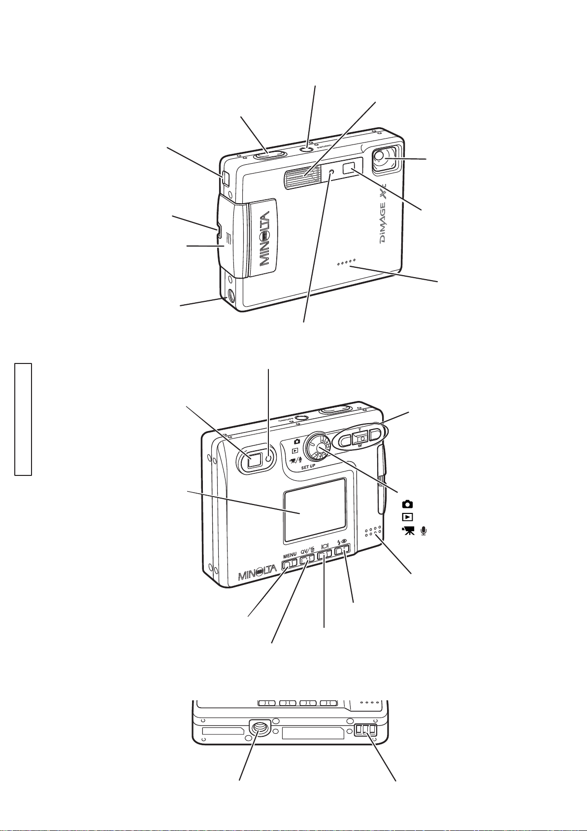
NAMES OF PARTS (Body)
AV-out-terminal/
USB-port
Shutter-release
Main switch
Flash
button
Lens
CHECK LIST
Strap eyelet
Battery/Card
chamber door
DC terminal
Viewfinder
LCD monitor
Self-timer lamp
Indicator lamp
Viewfinder window
Controller
Mode dial
Recording mode
Playback mode
Movie/Audio recording mode
/
SETUP
Setup mode
Microphone
Speaker
Flash-mode button
Menu button
Display button
QV/
Delete button
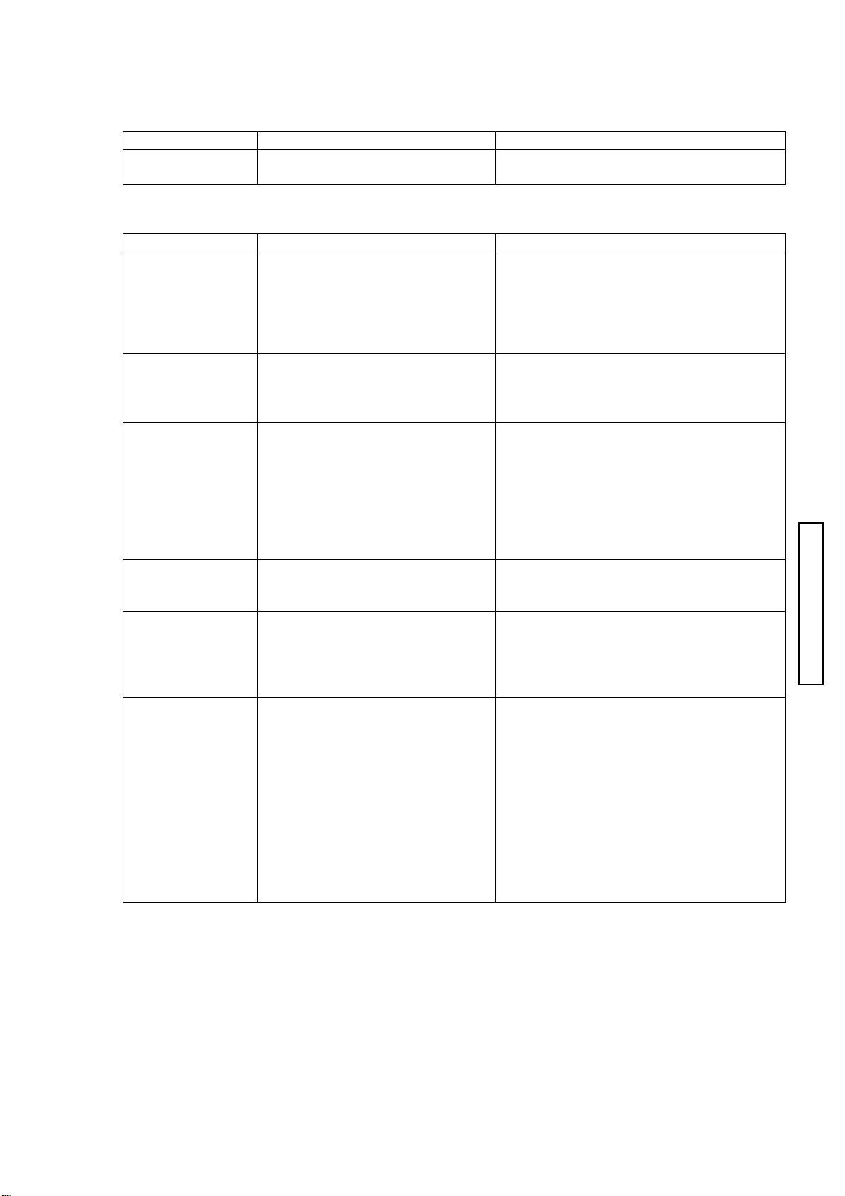
Tripod socket Chager contacts
Page 3
APPEARANCE and FUNCTION
e
Appearance
Item Procedure Requirement / Remarks
Appearance Check the appearance of the
camera visually.
Function
Item Procedure Requirement / Remarks
Battery
Installation
SD Memory Card
Installation
Main Switch ON
(Recording mode)
Viewfinder 1. Bring the camera to eye level. No dust or stain in the viewfinder.
Zoom 1. Press the up/down key of the
Button Functions
Flash-mode
button
Display button
QV/Delete button
1. Slide the battery/card chamber
door down and install the battery
into the camera.
1. Insert a SD memory card into
the camera.
1. Press the main switch.
controller.
Wideangle to Telephoto
Telephoto to wideangle
1. Press the button.
1. Press the button.
1. Press the button.
No scratches, stains, clearance gap
When opening, closing or sliding the
battery chamber door, its motion is not
sticking or loose.
After installing the battery, the battery is
not sticking or loose.
At installing the SD memory card, it is not
sticking or loose.
Pressing the card into the card slot and
then releasing ejects the card.
A live image appears on the LCD monitor.
When the SD memory card and battery
are inserted into the camera initially, a
message “Set date and time” appears on
the LCD monitor.
When the lens barrier opens, its sliding
motion is not sticking or loose. (Check in
both normal and inverted position)
Also, no shadows or an inclined image.
The key operation is smooth.
Image on the LCD or viewfinder zooms
smoothly.
Each time the button is pressed, flash mode
switches: Autoflash > Autoflash with red-ey
reduction > Fill-flash > Flash cancel > Night
portrait > Autoflash
Pressing the button switches:
Full display > Live image only > LCD off
Pressing the button switches:
Live view > Playback>Delete confirmation
(2786)A 3
CHECK LIST
Page 4

4 (2786)A
Menu button
Recording Mode
CHECK LIST
Item Procedure Requirement / Remarks
1. Press the button.
2. Press the left/right keys and
up/down keys.
1. Bring the camera to eye level
and press the shutter-release
button partway down. (S1 ON)
2. Press the shutter-release
button all the way down.(S2 ON)
3. Capture an image in self-timer
mode.
4. Capture an image with flash.
5. View the live image on display
with digital zoom.
Keys control the cursor and change the
settings.
“---“appears when the SD card is not
installed.
AE and AF are activated.
The indicator lamp next to the viewfinder
lights.
After the shutter release, the live view
briefly disappears, then reappears.
Selecting Menu > Basic > Drive mode >
Self-timer sets to self-timer mode.
At S2 ON, self-timer LED blinks and the
shutter will be activated by a 10-sec.
delay.
Set to fill-flash mode.
Flash fires at each shutter release.
After S2, LED blinks in red (charging)
and then in orange (data writing).
When setting to red-eye reduction mode,
the flash fires multiple bursts before the
main burst.
1. Selecting Menu > Custom2 > Digital
zoom selects digital zoom setting and
pressing the center of the controller
changes the setting.
2. Pressing the center of the controller to
select and then enter button sets to the
digital zoom.
3. Press the key up to set to telephoto.
4. Pressing the key continuously switches
optical zoom to digital zoom automatically
and the image will be enlarged by 1.1x,
1.2x, 1.3x…4.0x.
Page 5

(2786)A 5
Item Procedure Requirement / Remarks
Playback Mode 1. Turn the mode dial to playback
mode position.
2. Record an audio caption.
3. Playback the recorded audio
caption.
Menu setting Press the menu button. Pressing the menu button lights the LCD.
AC adapter Connect the AC adapter Pressing the main switch turns on the
Data Transfer
Mode
Insert a SD memory card
1.
into the camera.
Turn on the PC and connect
2.
the camera to the computer via
the USB cable.
3.
Turn on the camera.
4.
Open the folder in the camera.
(shown as removable drive)
To disconnect USB, perform
unplug-eject- process on the
computer, and press the power
switch and disconnect the camera
from the computer.
The latest image appears on the LCD
monitor.
Pressing the left/right keys scrolls to the
next recorded image.
1. Select an image to add an audio caption,
and press the menu button.
2. Select Basic > AudioCaption > Enter
, and start recording for 15 sec. at
maximum (keep 20cm from microphone)
3. Pressing the enter button stops
recording.
4. Pressing the menu button returns to
playback display.
Pressing the enter button starts the audio
playback.
Menu setting in enabled .
See Menu setting list in this manual.
camera.
The data transfer mode indicator
appears on the top left corner of the LCD
monitor.
CHECK LIST
Page 6

6 (2786)A
USB Connection (Data transfer mode)
When the camera is properly connected to
the computer via a USB cable, a removable disk icon
will appear in the “My Computer” folder.
For Windows98 and the Windows98 Second Edition,
the dedicated driver is required.
Files and folders
Std.folder
JPEG file (economy, standard, fine)
TIFF file and thumbnail (TIFF)
WAVE file (Voice memo/Audio caption)
MOV file (Movie recording)
WAVE file (Audio recording)
Date folder
E-mail copy folder
E-mail copy images created from images
in the Std. and date holder will be placed
CHECK LIST
DPOF file
Page 7

MENU settings
Recording mode
Basic Drive mode Single Default
Custom 1 Sensitivity ISO400
Custom 2 Color mode Color Default
(2786)A 7
Tab Menu option Setting Default
Self-timer
Continuous
Image size 2048x1536 Default
1600x1200
1280x960
640x480
Quality TIFF
Fine
Standard Default
Economy
White balance Auto Default
Daylight
Cloudy
Tungsten
Fluoresnt
Key func. Exp. Comp. Default
White balance
Drive mode
Sensitivity
Color mode
ISO200
ISO100
ISO50
Auto Default
Metering mode MultiSegment Default
Spot
Exp. Comp. -2 to +2
Noise reductn On Default
Off
Auto reset On Default
Off
B&W
Sepia
Voice memo On
Off Default
Date imprint YYYY/MM/DD
MM/DD/hr:min
Off Default
Digital zoom On
Off Default
Instant playback On
Off Default
0
CHECK LIST
Page 8

8 (2786)A
Playback mode
CHECK LIST
Movie/Audio mode
Tab Menu option Setting Default
Basic Delete This frame
Custom 1 Slide show Enter
Custom 2 DPOF set This frame
AudioCaption Enter
Lock This frame
Playback All frames
Duration 1 - 60sec. 5sec.
Repeat Ye s
Index print On
E-mail copy This frame
Image size 640x480 Default
All frames
MarkedFrames
All frames
MarkedFrames
Unlock all
MarkedFrames
No Default
All frames
MarkedFrames
Cancel all
Off Default
MarkedFrames
160x120
Tab Menu option Setting Default
Basic RecordingMode Movie Default
Image size 320x240 Default
White balance AUTO Default
Color mode Color Default
Audio
160x120
Daylight
Cloudy
Tungsten
Fluoresnt
B&W
Sepia
Page 9

Setup mode
Basic LCDbrightness Enter
Custom 1 Audio signals On Default
Custom 2 Reset default Enter
Indication Lamp
(2786)A 9
Tab Menu option Setting Default
Format Enter
File # memory On
Off Default
Folder name Std. form Default
Date form
Language
Shutter FX 1 Default
CustomRecord Focus signal
Volu me 3 (High)
Power off 30 min.
Date/Time set Enter
Date format YYYY/MM/DD
Video output NTSC
Transfer mode Data storage Default
日本語/JPN
English
Deutsch
Francais
Espanol
Off
2
Custom
Off
Shutter FX
2 Default
1 (Low)
10 min.
5 min.
3 min. Default
1 min.
MM/DD/YYYY
DD/MM/YYYY
PAL
Remote camera
Varies with each
Varies with each
Varies with each
destination
destination
destination
CHECK LIST
Color Status Description
Glowing Focus is locked and camera ready to take an image.
Green
Red
Orange Blinking quickly (8Hz) The camera is accessing the card.
Blinking quickly (8Hz) Focus is not confirmed.
Blinking slowly (2Hz) Camera shake warning
Off Movie mode
Glowing Power on (Recording, playback)
Blinking quickly (8Hz) Flash is being charged.
Power is insufficient for camera operation.
The card is full or locked.
The card cannot be used with the camera.
Page 10

10 (2786)A
PERFORMANCE
Check Grayscales, Color Reproduction, Ambient Exposure Accuracy and
Flash Exposure Accuracy to verify performance.
Capture images with the given condition, then read the color data with the
Color Calculator 2 (CD-ROM; 2766-0008-75).
Color Calculator 2 Installation
1. Load the Color Calculator 2 CD-ROM to the computer.
2. Click on English folder.
3. Double-click on SETUP.exe folder. The installer program starts and runs
automatically.
4. Follow the direction in the installation screen to the screen until “Finish”
appears.
Using Color Calculator 2
1. Click Program in Start menu, and click on “Color Calculator2”.
2. Open the desired image.
(For detailed operation, refer to ****)
3. Set the modes as below according to the check item.
CHECK LIST
Macbeth Color Checker
Check Item
Grayscales, Color
reproduction
Chart Macbeth Color Checker
Exposure/Flash control
Accuracy
Luminous surface of Light
Source, Gray Chart
Color Space sRGB
Color Display
Mode
RGB and L*a*b*
Calculate Mode Multi Area Center Single Area
Cropping Area
Size
20x20 pixels 256x256 pixels
4. In Multi Area mode, click and drag the edge of the frame to select the entire
color chart.
5. Click on Calculate button. Data calculation starts, and the result is listed
in the right window.
Multi Area mode: The readings for each of 24 areas are listed.
Center Single Area: The readings for the center area is listed.
B G R Y M C
1 2 3 4 5 6
Page 11

(2786)A 11
Grayscales
Measuring Condition Chart: Macbeth Color Checker
Light Source: Light Source-A (Tungsten) 6500 +/- 100 lux
Distance (from the subject): 1.2m
Focal-length: Telephoto
Focus: AF
White-balance: Auto
Image Quality: Standard
Image Size: 1600x1200
Be sure to set the chart right in front of the camera so that the chart center
aligns with the optical axis.
Standard Read L* value of each square, and check if all readings are within the
standard.
Chart L*
1 (White) 85 +/- 10
2 75 +/- 10
3 61 +/- 10
4 (Gray) 45 +/- 10
5 24 +/- 10
6 (Black) 6 +/- 10
Color Reproduction
Measuring Condition Chart: Macbeth Color Checker
Light Source:
Light Source-A (Tungsten) 6500 +/- 100 lux,
Light source-C (Light source-A + LB B16 filter),
White Fluorescent (FLW10W 700 +/- 200 lux) ,
Flash (Built-in)
Distance (from the subject): 1.2m
Focal-length: Telephoto
Focus: AF
White-balance: Auto
Image Quality: Standard
Image Size: 1600x1200
Be sure to set the chart right in front of the camera so that the chart
center aligns with the optical axis.
Standard Read a* and b* value of each square, and confirm that all readings
suffice the standard.
Light source-A
a* b*
B 20+/-15 -31+/-15
G -32+/-15 44+/-15
R 69+/-15 44+/-15
Y 10+/-15 72+/-15
M 67+/-15 16+/-15
C -19+/-15 -6+/-15
Light source-C
a* b*
B 35+/-15 -69+/-15
G -40+/-15 42+/-15
R 65+/-15 29+/-15
Y -2+/-15 72+/-15
M 64+/-15 -23+/-15
C -19+/-15 -21+/-15
CHECK LIST
Page 12

12 (2786)A
White Fluorescent lamp
a* b*
B 40+/-20 -61+/-20
G -39+/-20 44+/-20
R 55+/-20 30+/-20
Y -12+/-20 74+/-20
M 55+/-20 -18+/-20
C -11+/-20 -25+/-20
Ambient Exposure Accuracy
Measuring Condition Luminance Box: EV10
Distance (from the subject): Attach the lens tightly to luminous surface.
Focus: AF
White-balance: Auto
Image Quality: Standard
Image Size: 1600x1200
Standard Take multiple images, and check the reading of average G value meets the
standard.
Standard: Multi-segment; G= 155 to 175
Flash
a* b*
B 18+/-20 -32+/-20
G -35+/-20 31+/-20
R 51+/-20 20+/-20
Y -3+/-20 57+/-20
M 52+/-20 -24+/-20
C -14+/-20 -22+/-20
Flash Exposure Accuracy
Measuring Condition Chart: Standard Reflection Paper II (reflectance: 25%)
CHECK LIST
Be sure to set the chart right in front of the camera so that the chart center
Standard Take multiple images, and check the reading of average G value meets the
Spot ; G= 115 to 135
Light Source: Flash (Perform this check in darkroom)
Distance (from the subject): 1.5m
Focus: AF
White-balance: Auto
Image Quality: Standard
Image Size: 1600x1200
aligns with the optical axis.
standard.
Standard: G=130 to 160
Page 13

(2786)A 13
AAAA
Resolving Power
Equipment Required PC (IBM compatibles; Photoshop installed)
2766 Resolving Power Chart (W)
2766 Resolving Power Chart (T)
Fluorescent Stand SQ967W
SD memory Card
AC Adapter AC-4 or AC-5
Tripod
*1: 2766 Resolving Power Chart (W) contains 3 charts.
Set the A-chart at the center, then set the B-charts at its both side.
Align 3 charts with the positioning lines on them.
Check 1. Insert the SD memory card into the card slot of the camera, and set the
2766 Resolving Power Charts.
2. Set up the equipment as shown below.
3. Light up the chart evenly with Fluorescent Stand SQ967W.
Capture the both charts (for Wideangle, Telephoto) at the specified
position.
The dim lighting may result in the incorrect reading due to low contrast.
If the amount of the light is insufficient, capture each half separately.
4. Open the image with Photoshop.
Do not apply any image correction to test images on Photoshop.
Image correction such as Level, Curves or Contrast may cause incorrect
reading.
B B
CHECK LIST
5. Ensure that the reading is with in standard.
Camera Setting Image Size: 1600 x 1200
Image Quality: TIFF
Flash Mode: Cancel
Exposure Compensation: Use Exposure Compensation mode, if necessary.
Distance (from the chart): 1410 mm for wideangle, 1470 mm for telephoto
Page 14

14 (2786)A
y
d
Standard
Center Corners
Telephoto 950 lines or greater 625 lines or greater
Wideangle 1050 lines or greater 650 lines or greater
Reading
Number of lines
(Television resolution)
Reading
Number of lines
(Television resolution)
A 1400 G 800
B 1300 H 700
C 1200 I 600
D 1100 J 500
E 1000 K 400
F 900
B.C. Lock Voltage
Procedure 1. Press the main switch to start the camera.
2. Lower the voltage of the DC power supply little by little and press the
shutter release button partway down each time when changing the voltage.
Check the voltage when the power turned off.
Standard Ensure the reading meets the standard below.
Use B.C. Check Power Supply Adapter for 2760.
(Yellow plug: 0.5 ohm)
Fig. 1
B.C. Lock Voltage: 3.45V or below
CHECK LIST
Digital Multimeter
B.C. Check Power Supply Adapter
for 2760 (Yellow plug :0.5 ohm)
DC Power Supply
(4.2V, 3A)
Camera: Recording mode
LCD ON
How to connect the IC clip of the B.C. Check Power Suppl
Adapter for 2760 to the camera
1. Press and hold the end of IC clip to thrust the tip.
2. Insert the IC clip to the battery slot until it stops an
in parallel with the battery contact.
3. Rotate the IC clip by 90 degrees to hook the battery
contact.
How to disconnect the clip IC of the B.C. Check Power
Supply Adapter for 2760 to the camera
1. Follow the reverse procedure when disconnecting.
Do not deform the battery contact.
Page 15

(2786)A 15
)
Current Consumption
Standard Ensure the reading meets the standard below.
Use B.C. Check Power Supply Adapter for 2760(Fig.2).
(Yellow plug: 0.5 ohm)
Be sure to insert the SD memory card into the card slot.
Current Leak
Standard Ensure the reading meets the standard below.
Use B.C. Check Power Supply Adapter for 2760.
Measure the reading 16 hours** or longer after loading the battery.
Recording mode (LCD ON): 0.8A or below
Recording mode (LCD OFF): 10mA or below
(Yellow plug: 0.5 ohm; Fig. 2)
Current Leak: 280 microA or below
Note:
This model is equipped with a built-in secondary battery for date/time
backup. The camera battery (NP-200) supplies power regardless of
the main switch on/off. It takes at least 16 hours to charge the backup
battery fully.
Fig. 2
Camera setting:
Insert the SD memory
card to the card slot
when reading the
current consumption.
DC Power Supply (4.7V, 3A
CHECK LIST
B.C. Check Power Supply
Adapter for 2760 (Yellow
plug : 0.5 ohm)
Note:
Direct power from the leak tester (INT;
3V/6V) may disable camera setting.
Be sure to connect another condenser of 4700
microF <7981-9010-11> to the Leak Tester,
adding to the existing one in parallel.
Camera Leak Tester **
(Range: EXT)
 Loading...