

Page 1

(2786)A 1
REPAIR GUIDE
REPAIR GUIDE
This repair guide section contains the disassembly and adjustment procedures.
For the assembly procedure, follow the reverse procedure.
SYMBOLS
■:Cautions and keypoints
: Grease
: Adhesive
: Tool
CONTENTS Page
■Precautions --------------------------------------------------------------------------------------------------------------------- 2
■Discharge ----------------------------------------------------------------------------------------------------------------------- 3
1
Exterior parts, LCD, CP-1 Compl PWB Disassembly ----------------------------------------------------------------- 4
2
ST-1 Compl PWB, PW-1 Compl PWB Disassembly ------------------------------------------------------------------ 5
■PWB Diagram ----------------------------------------------------------------------------------------------------------------- 6
■Adjustments and Checks Required After Repair ----------------------------------------------------------------------- 7
■Adjustment sequence --------------------------------------------------------------------------------------------------------- 7
■Instruction for Adjustment Program ------------------------------------------------------------------------------------- 8
■Lens Adjustment (Focus in the Calibration section)------------------------------------------------------------------ 10
■AWB Adjustment (AWB in the Calibration section) ------------------------------------------------------------------ 11
■Missing Pixel (Defect) Compensation Adjustment (Test in the LCD section) ----------------------------------- 12
■Missing Pixel (Black) Compensation Adjustment (Test in the LCD section)------------------------------------ 13
■LCD Monitor Adjustment (HAFC/RGB Offset/Gain/R Bright/B Bright in the LCD section) --------------- 14
■USB Storage Information Registration ---------------------------------------------------------------------------------- 18
■Measuring Instruments, Tools and Jigs -------------------------------------------------------------------------------- 19
Page 2
2 (2786)A
■■
■Precautions
■■
Chemicals
Handle chemicals of high volatility with care, use of which will affect to your health and environment.
1. Store them sealed in a specific place to prevent exposure to high temperature or direct sunlight.
2. Avoid dividing them into small containers and prevent vaporization.
3. Keep containers sealed when not in use.
4. Avoid using them as much as possible. When required, remove only required amount from the
container to make full use.
Plastic parts
1. When cleaning plastic parts, use cleaning paper or cloth. Never use thinner, ketone, ether.
2. When installing plastic parts, insert the specific screws vertically to the parts. (Be careful not to
tighten too much.
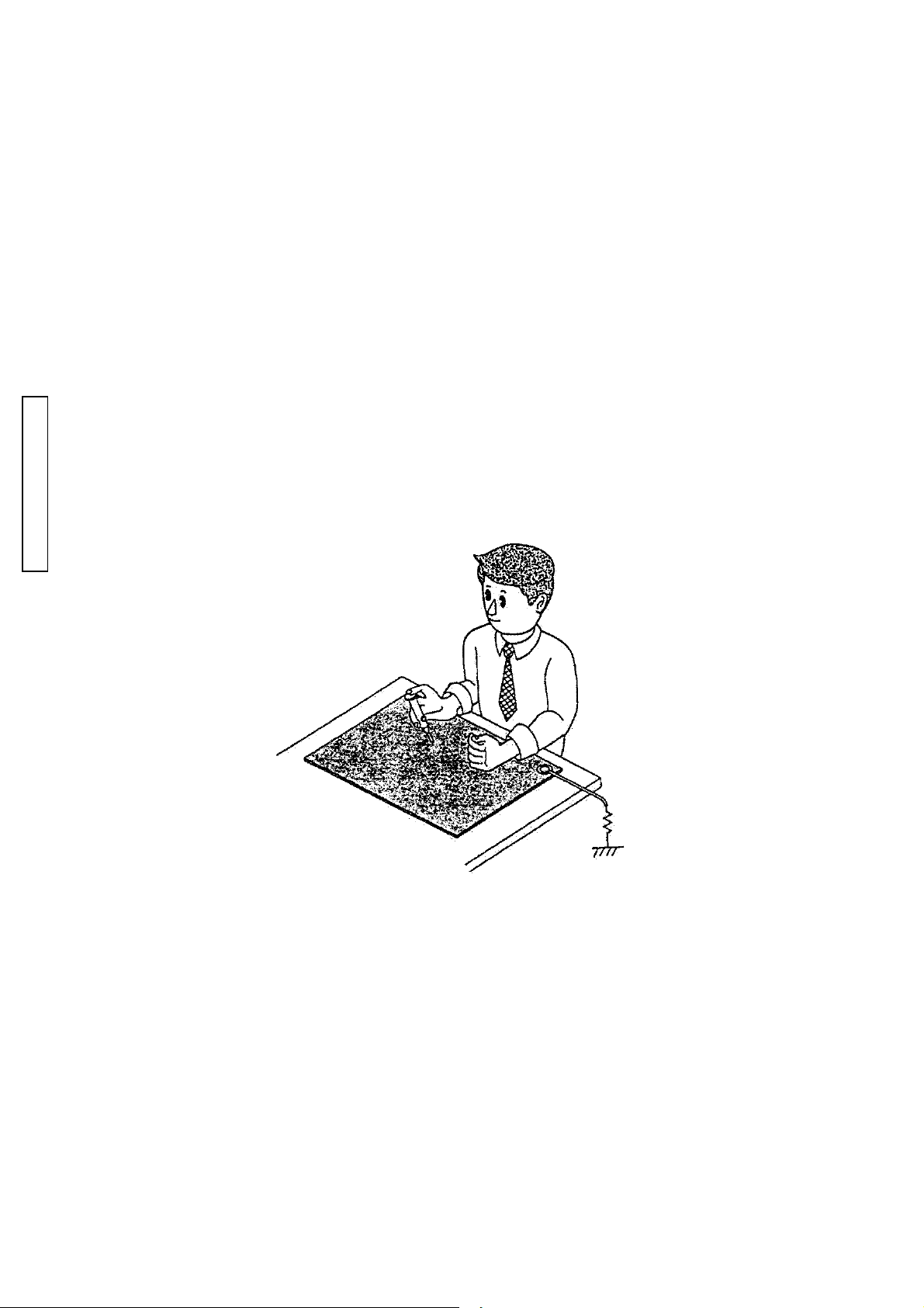
PCBs
Since PCBs use MOS IC, you must reduce static electricity. When repairing a PCB itself, or when
wiring, please perform your work as illustrated below.
If grounding is impossible, connect a cable to a steel desk or shelf.
REPAIR GUIDE
Keep touching the conductiveKeep touching the conductive
Keep touching the conductive
Keep touching the conductiveKeep touching the conductive
mat while you work.mat while you work.
mat while you work.
mat while you work.mat while you work.
Conductive MatConductive Mat
Conductive Mat
Conductive MatConductive Mat
1M1M
1M
1M1M
ΩΩ
Ω
ΩΩ
GNDGND
GND
GNDGND
Page 3
(2786)A 3
REPAIR GUIDE
Discharge
Before disassembly, be sure to discharge the main condenser in the following manner. (Fig. 1)
■■
Fig. 1Fig. 1
■
Fig. 1
■■
Fig. 1Fig. 1
Short-circuit with discharger or resistor of 200-300 ohm/3w.
Check voltage to make sure it is discharged.
Page 4
4 (2786)A
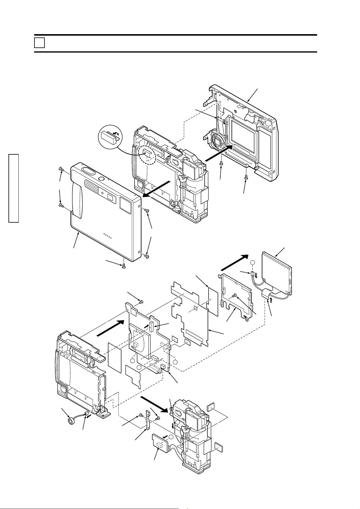
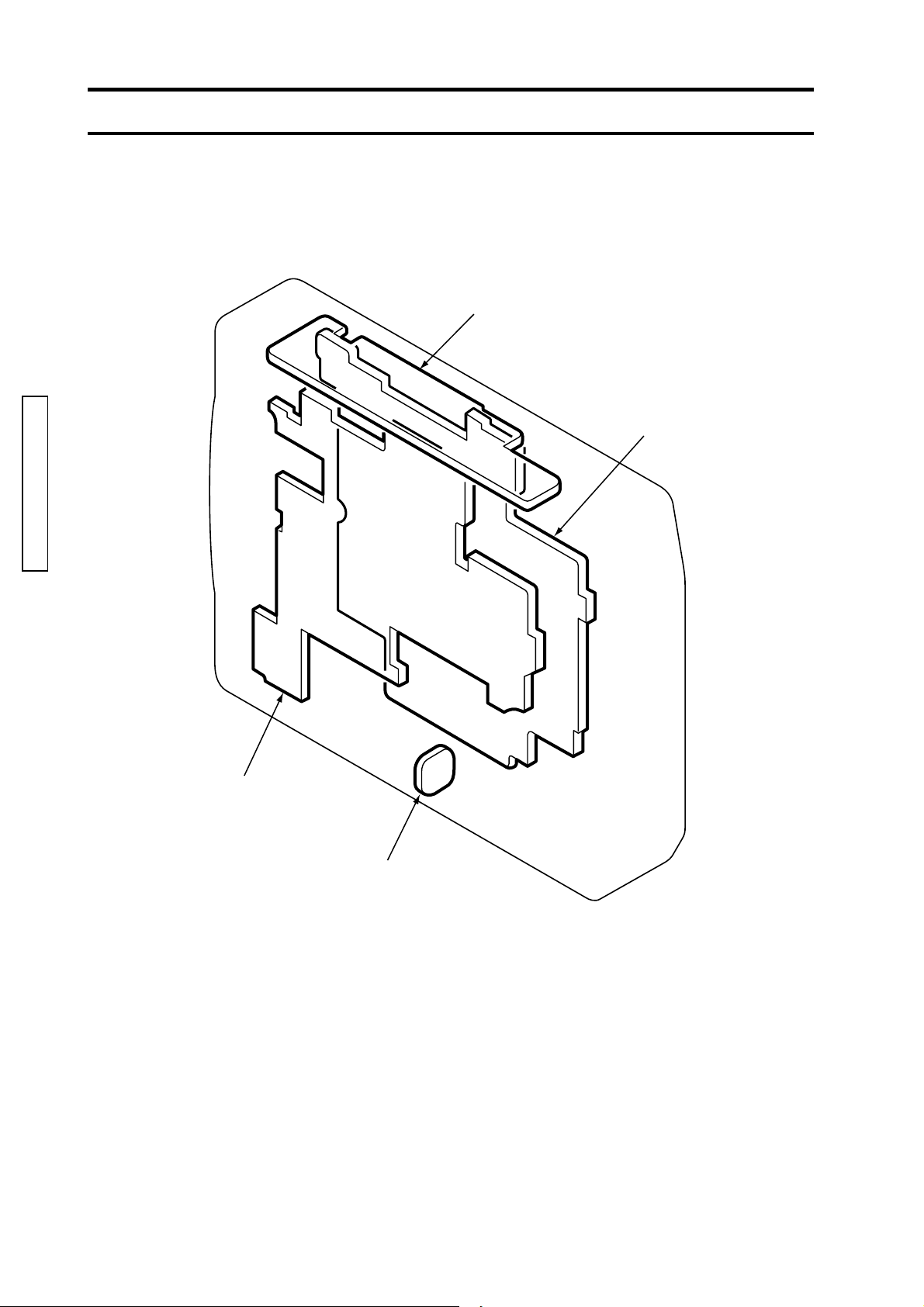
1 Exterior parts, LCD, CP-1 Compl PWB Disassembly
Disassemble the parts in order from 1 to 22.
When assembling, follow the reverse procedure.
4
3
REPAIR GUIDE
2
1
2
1
7
5
2
11
C
6
14
9
15
10
8
12
19
18
21
22
C
A
B
16
13
20
B
A
17
Page 5
REPAIR GUIDE
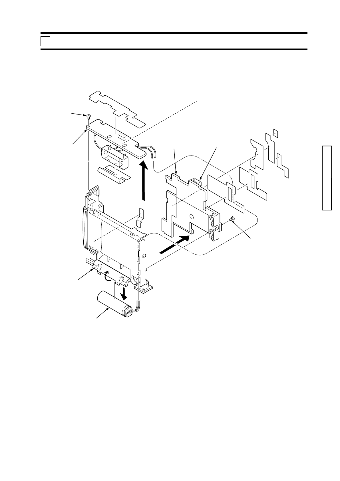
ST-1 Compl PWB,PW-1 Compl PWB Disassembly
2
Disassemble the parts in order from 1 to 7.
When assembling, follow the reverse procedure.
1
(2786)A 5
5
7
4
6
2
3
Page 6
6 (2786)A
■■
■PWB Diagram
■■
ST‑1Compl PWBST‑1Compl PWB
ST‑1Compl PWB
ST‑1Compl PWBST‑1Compl PWB
CP‑1Compl PWBCP‑1Compl PWB
CP‑1Compl PWB
CP‑1Compl PWBCP‑1Compl PWB
REPAIR GUIDE
PW‑1Compl PWBPW‑1Compl PWB
PW‑1Compl PWB
PW‑1Compl PWBPW‑1Compl PWB
ST‑2Compl PWBST‑2Compl PWB
ST‑2Compl PWB
ST‑2Compl PWBST‑2Compl PWB
Page 7

(2786)A 7
REPAIR GUIDE
Adjustments and Checks Required After Repair
After making replacement or repair of the following items, check or adjust as required in the table.
Be sure to perform in a sequential order from the top in the table.
☆: Necessary check ★: Necessary adjustment
Parts
Adjustment/Ch eck item
Lens Adjustment Page 10
AWB Adjustment Page 11
Missing Pixel (Defect)
Compensation Adjustment
Missing Pixe l ( B lac k )
Compensation Adjustment
LCD Monitor Adjustment Page 14
USB Storage Information
Registration
Re solvin g Po w e r Check Ch e ck List
Color Reproduction Check List
Ambient Exposure Accuracy Check List
Flash Exposure Accuracy Check List
Grayscales Che ck List
B.C. Lock Voltage Check List
Current Consumption Check List
Current Leak Check List
Page 12
Page 13
Page 18
CP-1
Compl
PWB
(#0408)
Replacement Replacement Replacement Replacement Replacement
★★★★
★★★★
★★★★
★★★★
★★★ ★
★
☆☆☆☆☆
☆☆☆☆☆
☆☆☆☆☆
☆☆☆☆☆
☆☆☆☆☆
☆☆☆☆☆
☆☆☆☆☆
☆☆☆☆☆
PW-1
Compl
PWB
(#0432,0452)
ST-1
Compl
PWB
(#0406)
Lens
Assy
(#3254-0600)
LCD
(0460)
Adjustment sequence
■Some adjustments should be performed in the order
1.Lens Adjustment
2.AWB Adjustment
3.Missing Pixel (Defect)Compensation Adjustment
4.Missing Pixel (Black)Compensation Adjustment
Adjust in the order from 1 to 3.
Adjust 4 after 2.
The other adjustments can be done independently.
■ Note of the PW-1 Compl PWB (#0432,0452)
Never turn the VR501 and VR502 on the PW-1 Compl PWB (#0432,0452), or the PW-1 Compl PWB
(#0432,0452) has to be replaced.
The output voltage adjustment and the oscillating frequency adjustment of the individual PWB can only
be performed at the parts assembly line, not available with service facilities.
For the same reason, always replace with the PW-1 Compl PWB (#0432,0452) as a set.
Page 8

8 (2786)A
Instruction for Adjustment Program
Adjust #2786with F/X Series Adjustment Program(Ver.1.0).
F/X Series Adjustment Program is usable for the 2776,2777,2783,2785,2788 and 2786 adjustment.
■ System Required
Computer: IBM PC/AT compatible running Windows98, Windows98 Second Edition, Windows 2000
Professional* or Windows Me. *: Windows 2000 Professional is recommended for stable operation.
Memory: A minimum of 40MB RAM
Hard Disk Space: 15MB or more free hard disk space
Monitor: Capable of 32000 colors or greater monitor with a minimum resolution of VGA
■ Contents of F/X Series Adjustment Program CD Ver.1.0
F/X Series Adjustment Program CD (The folders are underlined.)
REPAIR GUIDE
AD J Pro gram
DscCalDi.exe
Camapi32.dll
Driver so ft fo r W in.98
MD SC PD R .inf
MD SC PD R .pdr
MD SC STO R .in f
MD SC STO R .sys
Siemens-Star-Chart.bmp
■ Adjustment Program Installation
1. Insert the F/X Series Adjustment Program CD into the CD-ROM drive.
2. Double-click on the CD-ROM icon, then select "ADJ Program" folder, and copy the folder to the
computer's desktop.
■ Launching Adjustment Program
The dedicated USB driver included in F/X Series Adjustment Program must be installed for Windows98
and Windows98 Second Edition. See Instruction of USB Driver Soft for Windows98. (pg. 10)
1. Connect the camera to the computer with the USB cable USB-500.
2. Start "DscCalDi.exe" file from the ADJ Program on the computer's desktop.
The adjustment screen appears as shown in Fig. 1.
■Adjustments available with Adjustment Program ("DscCalDi.exe" )
Lens Adjustment (Focus in the Calibration section)
Fig. 1 Adjustment screen of F/X SeriesFig. 1 Adjustment screen of F/X Series
Fig. 1 Adjustment screen of F/X Series
AWB Adjustment (AWB in the Calibration section)
Missing Pixel (Black/Defect) Compensation Adjustment
(LCD section)
LCD Monitor Adjustment
(HAFC/RGB Offset/Gain/R Bright/B Bright/VomPP in
the LCD section)
USB Storage Information Registration
(in the USB Storage section)
Fig. 1 Adjustment screen of F/X SeriesFig. 1 Adjustment screen of F/X Series
Adjustment Program ("DscCalDi.exe" )Adjustment Program ("DscCalDi.exe" )
Adjustment Program ("DscCalDi.exe" )
Adjustment Program ("DscCalDi.exe" )Adjustment Program ("DscCalDi.exe" )
Calibration
AWB
Focus
UV Matrix
Cal Mode
Cal Data
USB storage
VID
Get
PID
Set
Upload
OK
LCD Type
OK
Firmware
Image
Initialize
EVF
LCD
R Bright
RGB Offset
Tint
VCO
H AFC Test
Serial
Set
B Bright
VCOMDC
Gain
VCOMPP
Phase
Setting
Language
Set
Rev.
Set
Video Mode
Set
■Caution
Never click "Initialize" or the following items in the adjustment screen.
Cal Mode and Cal Data in the Calibration section (Default settings: 0)
All in the Upload section
LCD Type
All in the Setting section
Page 9

REPAIR GUIDE
(2786)A 9
Installation of USB Driver (Windows98/98 Second Edition only)
The dedicated USB driver included in F/X Series Adjustment Program must be installed for Windows98
and Windows98 Second Edition. If the USB driver supplied with DiMAGE Xt has been installed on the
computer, the adjustment program cannot be launched and an error message "camera is not connected"
appears on the screen. Install the dedicated USB driver with one of the following procedures.
<Type-1><Type-1>
<Type-1>
<Type-1><Type-1>
If the USB driver supplied with DiMAGE Xt has never been installed, follow the procedure below.
1. Connect the camera to the computer via the USB cable.
The "Add NEW Hardware Wizard" window appears.
2. Choose "Specify a location" in the dialog and select "Driver soft for Win.98" folder in the copied " ADJ
Program" folder.
3. Click "Next" to start installation.
4. Follow the direction in the screen until "Finish" appears, and click "Finish".
5. After installing the driver completely, right-click on My Computer on the desktop, and click
Property. The system property window appears.
6. Click the Device Manager tab. The device manager window appears.
7. Confirm that the following devices are listed in the device manager window.
"MINOLTA DiMAGE F200" under the Disk drives
"MINOLTA Digital Camera Mass Storage Driver" under the Universal Serial Bus controllers
<Type-2><Type-2>
<Type-2>
<Type-2><Type-2>
If the USB driver supplied with DiMAGE Xt has already been installed, follow the procedure below.
1. Connect the camera to the computer via the USB cable.
2. Right-click on My Computer on the desktop, and click Property.
The system property window appears.
3. Click the Device Manager tab. The device manager window appears.
4. Confirm that the following devices are listed in the device manager window.
"MINOLTA USB WDM STORAGE" under the Disk drives
"MINOLTA DiMAGE Xt" under the Universal Serial Bus controllers
5. Double click "MINOLTA DiMAGE Xt" under the Universal Serial Bus controllers.
6. Click the Driver tab and click "Update driver".
The "Update Device Driver Wizard" window appears.
7. Select "Specify a location" in the dialog and select "Driver soft for Win.98" folder in the copied "ADJ
Program" folder.
8. Click "Next" to start installation.
9. Follow the direction in the screen until "Finish" appears, and click "Finish".
10. After updating the driver completely, confirm that the following devices are listed in the device
manager window.
"MINOLTA DiMAGE Xt" under the Disk drives
"MINOLTA Digital Camera Mass Storage Driver" under the Universal Serial Bus controllers
<Memo><Memo>
<Memo>
<Memo><Memo>
When the camera is connected to the computer, Serial number information is usable as the connecting
identification. If the serial number information involved in the camera is different from the recorded
serial number of the adjustment program in the computer, the operating system automatically search
the best driver for the device. When both USB drivers supplied with DiMAGE Xt and ADJ Program are
installed in the computer, the operating system may select the USB driver supplied with DiMAGE Xt as a
best driver. In this case, the adjustment program cannot be launched and an error message "Camera is
not connected" appears on the screen. Install the dedicated USB driver with the above procedure <Type-2>.
Setup of Siemens Star Chart Image
The Siemens Star Chart is used in the lens adjustment on page 11.
Prepare the chart with one of the following procedures.
Copy the attached Siemens Star Chart on the last page in 2783 repair guide to enlarge to 11" x 17" or
A3 size paper (x1.414).
Launch Photoshop, then open the "Siemens Start Chart.bmp" file from the F/X Series Adjustment
Program CD, and print it to 11" x 17" or A3 size paper.
Page 10

10 (2786)A
Forcus Resylt
P0=3451
P1=199
C0=-4
C1=-18
C2=-16
STD_AFPOS=633
DscCalDi
OK
Lens Adjustment (Focus in the Calibration section)
This adjustment creates the compensation data for LB value.
Whenever after replacing the CP-1 Compl PWB (#0408), the PW-1 Compl PWB (#0432,0452), the ST-1
Compl PWB (#0406) or the Lens Assy (#3255-0600), be sure to perform the adjustment.
■ Equipment Required
PC (IBM PC/AT Compatible Computer onto which the F/X Series Adjustment Program is installed)
USB cable USB-500
AC Adapter AC-6
Siemens Star Chart
Fluorescent Stand SQ967W
■ Preparation
Light up the chart evenly with Fluorescent Stand SQ967W.
■ Adjustment
1. Turn the mode dial to Auto-recording position.
2. Press the up key (t) to set the lens to the telephoto position.
3. Set the Siemens Star Chart 150cm +/- 3cm apart from the front of the lens. (Fig.1)
Be sure to align the center of the Siemens Star Chart with the center of the image on the LCD
REPAIR GUIDE
monitor.
4. Connect the camera to the computer with the USB cable USB-500, and start Adjustment Program
(DscCalDi.exe).
5. Click "Focus" in the adjustment screen.
"Execute AWB&AGC Gain Calibration. Yes or No" appears on the screen.
6. Click "Yes".
The camera performs adjustment, then the Lens adjustment value is displayed on the screen. (Fig.
2)
7. Confirm the "STD_AFPOS"and P0 reading is not 0 "zero".
0 "zero" means the adjustment failed. Check the setup and re-adjust.
8. Click "OK" to return to the adjustment screen.
Fig. 1Fig. 1
Fig. 1
Fig. 1Fig. 1
CameraCamera
Camera
CameraCamera
150cm150cm
150cm
150cm150cm
Fig. 2Fig. 2
Fig. 2
Fig. 2Fig. 2
Siemens Star ChartSiemens Star Chart
Siemens Star Chart
Siemens Star ChartSiemens Star Chart
±±
3cm3cm
±
3cm
±±
3cm3cm
Page 11

(2786)A 11
REPAIR GUIDE
AWB Adjustment (AWB in the Calibration section)
This adjustment creates the compensation data for WB output against color temperature of the light
source.
Whenever after replacing the CP-1 Compl PWB (#0408), the PW-1 Compl PWB (#0432,0452), the ST-1
Compl PWB (#0406) or the Lens Assy (#3255-0600), be sure to perform the adjustment.
Perform this adjustment in darkroom.
■ Equipment Required
PC (IBM PC/AT Compatible Computer with the F/X Series Adjustment Program is installed)
USB cable USB-500
AC Adapter AC-6
Color Viewer LV-1450DC
■ Preparation
Perform the adjustment 30 minutes or longer after turning on the Color Viewer.
The Color Viewer should be checked and adjusted according to its maintenance instruction on page 23
in 2783 repair guide.
■ Adjustment
1. Turn the mode dial to Auto-recording position.
2. Press the down key (w) to set the lens to the wideangle.
3. Set the camera and Color Viewer as illustrated in Fig 1.
4. Connect the camera to the computer with the USB cable USB-500, and start Adjustment Program
(DscCalDi.exe).
5. Click "AWB" in the adjustment screen.
"Execute AWB&AGC Gain Calibration. Yes or No" appears on the screen.
6. Click "Yes".
The camera performs adjustment, then the AWB adjustment value is displayed on the screen.
7. Click "OK" on the screen to return to the adjustment screen.
Fig. 1Fig. 1
Fig. 1
Fig. 1Fig. 1
CameraCamera
Camera
CameraCamera
Color Viewer LV-1450DCColor Viewer LV-1450DC
Color Viewer LV-1450DC
Color Viewer LV-1450DCColor Viewer LV-1450DC
Page 12

12 (2786)A
Missing Pixel (Defect) Compensation Adjustment (in the LCD section)
The adjustment is an image correct function that can restore the bright spots at long exposure.
Whenever after replacing the CP-1 Compl PWB (#0408), the PW-1 Compl PWB (#0432,0452), the ST-1
Compl PWB (#0406) or the Lens Assy (#3255-0600), be sure to perform the adjustment.
■ Equipment Required
PC (IBM PC/AT Compatible Computer with the F/X Series Adjustment Program is installed)
USB cable USB-500
AC Adapter AC-6
■ Adjustment
1. Turn the mode dial to Auto-recording position.
2. Connect the camera to the computer with the USB cable USB-500, and start Adjustment Program
(DscCalDi.exe).
3. Click the scroll arrow of "Test" in the LCD section of the adjustment screen, and select "CCD Defect"
from the pop-up menu of "Test".
"CCD Defect Detection. Yes or No" appears on the screen.
4. According to the screen, click "Yes".
The camera electronically makes 4-sec. exposure to map out dead pixels. Up to 512 pixels can be
restored at a time. The number of the missing pixels is displayed on the screen. (Fig. 1)
REPAIR GUIDE
Fig. 1Fig. 1
Fig. 1
Fig. 1Fig. 1
DSC
Dsc Calibration
Cal.
CCD Results :
number=512
OK
Copy
5. Click "OK" on the screen to return to the adjustment screen.
■ Adjustment Error ("Defect NG")
When the "Defect NG" appears during adjustment, take the following actions.
-Turn off the camera for 30 minutes or longer to cool down before re-adjusting.
-If the same error appears after re-adjustment, the CCD may be defective.
-Replace the Lens Barrel Assy (#3255-0600).
Page 13

(2786)A 13
REPAIR GUIDE
Missing Pixel (Black) Compensation Adjustment (in the LCD section)
The adjustment is an image correct function that can restore the black spots at exposure.
Whenever after replacing the CP-1 Compl PWB (#0408), the PW-1 Compl PWB (#0432,0452), the ST-1
Compl PWB (#0406) or the Lens Assy (#3255-0600), be sure to perform the adjustment.
■ Equipment Required
PC (IBM PC/AT Compatible Computer with the F/X Series Adjustment Program is installed)
USB cable USB-500
AC Adapter AC-6
Color Viewer LV1450DC
■ Preparation
Perform the adjustment 30 minutes or longer after turning on the Color Viewer.
■ Adjustment
1. Turn the mode dial to Auto-recording position.
2. Press the down key (w) to set the lens to the wideangle.
3. Set the Color Viewer from the front of the lens. (Fig.1)
4. Connect the camera to the computer with the USB cable USB-500, and start Adjustment Program
(DscCalDi.exe).
5. Click the scroll arrow of "Test" in the LCD section of the adjustment screen, and select "CCD Black"
from the pop-up menu of "Test".
The camera electronically makes exposure to map out dead pixels. Up to 512 pixels can be restored
at a time. The number of the missing pixels is displayed on the screen. (Fig. 2)
6. Click "OK" on the screen to return to the adjustment screen.
■ Adjustment Error ("Defect NG")
When the "Defect NG" appears during adjustment, the CCD may be defective.
-Replace the Lens Barrel Assy (#3255-0600).
Fig. 1Fig. 1
Fig. 1
Fig. 1Fig. 1
Fig. 2Fig. 2
Fig. 2
Fig. 2Fig. 2
DSC
Dsc Calibration
Cal.
CCD Black Results :
number=0
OK
Copy
CameraCamera
Camera
CameraCamera
Color Viewer LV1450DCColor Viewer LV1450DC
Color Viewer LV1450DC
Color Viewer LV1450DCColor Viewer LV1450DC
Page 14

14 (2786)A
LCD Monitor Adjustment (HAFC/RGB Offset/Gain/R Bright/B Bright in the LCD section)
The adjustment sets the color balance and position of the LCD monitor.
Whenever after replacing the CP-1 Compl PWB (#0408), the PW-1 Compl PWB (#0432,0452) or the ST1Compl PWB (#0406), be sure to perform the adjustment.
For LCD Monitor Adjustment, Oscilloscope is required. This manual assumes the procedure with Digital
Storagescope DS-8706. When using other model of the oscilloscope, the digital storage function is required.
■ Equipment Required
PC (IBM PC/AT Compatible Computer with the F/X Series Adjustment Program is installed)
USB cable USB-500
AC Adapter AC-6
Digital Storagescope DS-8706
■ Preparation
1. Remove the Cabinet Back (#0132/0152/0172) and LCD(#0460) from the body.
2. Solder 7 lead wires of the 5cm length to the designated test points (CL-410,CL411, CL412, CL413,
CL414, CL416, GND) on the CP-1 Compl PWB (#0408). (Fig. 1)
3. Connect the flex of the Cabinet Back (#0132/0152/0172) and LCD(#0460) to the connectors (CN108 and
CN352).It is unnecessary to fit the Cabinet Back (#0132/0152/0172) to the body.
REPAIR GUIDE
4. Turn the mode dial to Auto-recording position.
5. Connect the camera to the computer with the USB cable USB-500, and start Adjustment Program
(DscCalDi.exe).
6. Check the LCD "HAFC" value in the adjustment menu, and select the same value from the pop-up
menu by clicking the down button. (LCD turns to display as shown in Fig.2 by inputting the value.
Confirm that the LCD is in the condition as shown in Fig.2 before measuring the waveform.)
Fig. 1Fig. 1
Fig. 1
Fig. 1Fig. 1
CL410
(XENB)
CL412(B)
CL413(G)
CL414(R)
CL416
(CSYNC)
GND
CL411
(COM)
Fig. 2Fig. 2
Fig. 2
Fig. 2Fig. 2
■LCD monitor adjustment items.
1.LCD H AFC Adjustment
2.LCD RGB Offset Adjustment
3.LCD Gain Adjustment
4.LCD Red Brightness Adjustment
5.LCD Blue Brightness Adjustment
6.LCD VcomPP
Adjust "3. LCD Gain" after completing "2. LCD RGB Offset" adjustment.
Adjust "4. LCD Red Brightness" and "5. LCD Blue Brightness" after completing "3. LCD Gain" adjust-
ment.
The other adjustments can be done independently.
Page 15

REPAIR GUIDE
■ Setup of Digital Storagescope DS-8706
1. Connect the CH1 and CH2 probes to Digital Storagescope
DS-8706.
2. Set the probe to the magnification "x1".
3. Set MENU of AUTO SET in the following orders.
1) Press the MENU button (3-1) to display the "f:MENU
SELECT".
2) Turn the FUNCTION dial (3-2) to select "MEASURE".
3) Press the FUNCTION dial.
4) Turn the FUNCTION dial to select "MEASURE(B)".
5) Press the FUNCTION dial.
The MEASURE(B) adjust window appears and "OFF" is
high-lighted.
6) Turn the FUNCTION dial to select "[6]T".
7) Press the FUNCTION dial.
8) Press the MENU button so the menu disappears.
The clip of CH2 probe's GND is not used.
Align the cursor with the center of the waveform as illus-
trated in Fig. 4.
■ Adjustment
1. LCD H AFC Adjustment (Horizontal Auto Frequency
Control)
1) Connect the CH1 probe to CL416 and to the GND,
and the CH2 probe to CL410. Two waveforms appear.
2) Click the scroll arrow of "H AFC" in the LCD section of
the adjustment screen, and select the number from the
pop-up menu of "H AFC" until the width-A reading
(from the rise of CL416's waveform to the fall of CL410's
waveform) meets the standard.
Fig. 5Fig. 5
Fig. 5
Fig. 5Fig. 5
3-13-1
3-1
3-13-1
CL410
(CH2)
CL416
(CH1)
Fig. 3Fig. 3
Fig. 3
Fig. 3Fig. 3
Fig. 4Fig. 4
Fig. 4
Fig. 4Fig. 4
(2786)A 15
○○○
○○○○○○
AA
A
AA
○○○○○○
A
○○○
3-23-2
3-2
3-23-2
Standard: Width-A = 4.9 +/- 0.1 micro sec.
2. LCD RGB Offset Adjustment (Brightness Control)
1) Connect the CH1 probe to CL413 and to the GND.
2) A waveform appears. Click the scroll arrow of "RGB
Offset" in the LCD section of the adjustment screen,
and select the number from the pop-up menu of "RGB
Offset" until the waveform of CL413 meets the standard.
Standard: 0.5V +/- 0.1V
Fig. 6Fig. 6
Fig. 6
Fig. 6Fig. 6
CL410
(CH2)
CL416
(CH1)
0.5V ±
0.1Vp-p
CL413
Page 16

16 (2786)A
3. LCD Gain Adjustment (Contrast Control)
1) Connect the CH1 probe to CL413 and to the GND.
2) A waveform appears. Click the scroll arrow of "Gain"
in the LCD section of the adjustment screen, and
select the number from the pop-up menu of "Gain"
until the waveform of CL413 meets the standard.
Standard (CL413): 3.4V +/- 0.1 V
4. LCD Red Brightness Adjustment (Red Signal Control)
1) Connect the CH1 probe to CL413 and to the GND, and
the CH2 probe to CL414.
2) Two waveforms appear. Click the scroll arrow of "R
Bright" in the LCD section of the adjustment screen,
and select the number from the pop-up menu of "R
Bright" until the waveform of CL414 meets the standard.
Fig. 7Fig. 7
Fig. 7
Fig. 7Fig. 7
Fig. 8Fig. 8
Fig. 8
Fig. 8Fig. 8
3.4V ±
0.1Vp-p
CL413
VG
REPAIR GUIDE
5. LCD Blue Brightness Adjustment (Blue Signal Control)
1) Connect the CH1 probe to CL413 and to the GND, and
the CH2 probe to CL412.
2) Two waveforms appear. Click the scroll arrow of "B
Bright" in the LCD section of the adjustment screen,
and select the number from the pop-up menu of "B
Bright" until the waveform of CL412 meets the standard.
Standard (CL414): (VG - 0.1)V +/- 0.1 V
Standard (CL412): (VG + 0.15)V +/- 0.1 V
Fig. 9Fig. 9
Fig. 9
Fig. 9Fig. 9
CL413
(VG-0.1)
±0.1Vp-P
CL414
VG
CL413
CL412
(VG+0.15)
±0.1Vp-p
Page 17

REPAIR GUIDE
6. LCD VcomPP Adjustment
1) Connect the CH1 probe to CL411 and to the GND.
2) A waveform appears. Click the scroll arrow of
"VcomPP" in the LCD section of the adjustment
screen, and select the number from the pop-up menu
of "VcomPP" until the waveform of CL411 meets the
standard.
Standard (CL411): 3.25V +/- 0.1 V
Fig. 10Fig. 10
Fig. 10
Fig. 10Fig. 10
(2786)A 17
3.25V ±
0.1Vp-p
CL411
Page 18

18 (2786)A
USB Storage Information Registration
For USB to work, you must input the correct USB storage information to the camera (#2786).
Otherwise, problem may occur while the camera is connected to the computer via USB cable.
Always ensure that the USB storage information after repairing it .
Whenever after replacing the CP-1 Compl PWB (#0408), be sure to perform the USB storage information
registration.
■ Equipment Required
PC (IBM PC/AT Compatible Computer with the F/X Series Adjustment Program is installed)
USB cable USB-500
AC Adapter AC-6
■ Procedure
1. Turn the mode dial to Auto-recording position.
2. Connect the camera to the computer with the USB cable USB-500, and start Adjustment Program
(DscCalDi.exe).
3. Click "Get" in the USB Storage section of the adjustment screen. (Fig. 1)
4. Ensure that USB storage information as below appears on the computer's screen.
VID :MINOLTA
PID :DIMAGE Xt
REPAIR GUIDE
Serial :Serial number of the camera
Rev. :1.00
If any information appears incorrectly, type the correct data as above, then click "Set" at the
left-bottom corner the computer's screen or click "Set" next to each USB storage information
individually.
■ Caution
Be sure to confirm the USB Storage Information is displayed as above. Once any wrong information is
registered, cancellation is impossible. Especially, "VID" and "PID" are important to connect the camera
to the computer. If the information is wrong, the camera cannot be activated in adjustment mode. In
this case, replacing the CP-1 Compl PWB (#0408) is required.
When more than one camera is connected to the computer, serial number information is usable as their
identification.
Fig. 1Fig. 1
Fig. 1
Fig. 1Fig. 1
Calibration
AWB
Focus
UV Matrix
Cal Mode
Cal Data
USB storage
VID
Get
PID
Set
OK
OK
Upload
Firmware
Image
Initialize
EVF
LCD Type
LCD
R Bright
RGB Offset
Tint
VCO
H AFC Test
Serial
Set
Set
Rev.
B Bright
Gain
Phase
Set
Set
VCOMDC
VCOMPP
Setting
Language
Video Mode
Page 19

(2786)B 19
REPAIR GUIDE
Measuring Instruments, Tools and Jigs
■IBM PC/AT compatibles running Windows98, Windows98 Second Edition or Windows 2000 Professional
and with a USB port as standard interface (Photoshop 6.0 is required for Windows 2000 Professional.)
IBM PC/AT compatibles computer running Windows95 is useful for the performance check with a card
drive and an SD memory card adapter
■A 640 x 480 dots or greater Color Monitor capable of displaying 32000 or greater colors
■Adobe Photoshop
■USB cable USB-500
■Digital Storagescope DS-8706
■Luminance Box (L-2101, L-2111) or Multi Camera Tester (EF-8301)
■DC Power Supply (PR18-5A or MTR 18-3)
■Digital Multimeter (Fluke 83)
■Camera Leak Tester (CL-1101 or CL-1201)
■Macbeth Color Checker <2755-0008-75>
■White Fluorescent (FLW10W) <2757-0007-75> or White Fluorescent (FLW15W) <2757-0012-75>
■B.C. Check Power Adapter for 2760 <2760-0013-76>
■Resolving Power Chart (W) <2766-0005-75>
■Resolving Power Chart (T) <2766-0005-76>
■Color Calculator Ⅱ <2766-0008-75>
■F/X Series Adjustment Program CD Ver.1.0 <7981-5003-01> *1
■Reflection Paper II <7981-3001-52>
■Color Viewer LV-1450DC <7981-8105-01> *2
■Fluorescent Stand SQ967W <7981-9012-61>
■Light Source-A (Tungsten; See Light Source-A Maintenance.)
■Light source-C (Light source-A + Color Temperature Filter LB B16)
Color Temperature Filter LB B16 <2757-0005-75>
■SD Memory Card (for test image storage)
■AC Adapter AC-6
■Tripod
*1 : F/X Series Adjustment Program is usable with 2776,2777,2783,2785,2788 and 2786.
*2 : Input voltage :100 to 240V
Change the adapter plug acording to each situation.
 Loading...