


Tunnel 50 Digit
Minipack-torre S.p.A.
Via Provinciale, 54 - 24044 Dalmine (BG) - Italy
Tel. (035) 563525 – Fax (035) 564945
E-mail: info@minipack-torre.it
http://www.minipack-torre.it
IT ISTRUZIONI PER L’INSTALLAZIONE, L’USO E LA MANUTENZIONE
EN INSTALLATION, OPERATION AND MAINTENANCE
DE INSTALLATIONS-, GEBRAUCHS- UND WARTUNGSANLEITUNG
FR INSTRUCTIONS POUR L’INSTALLATION, L’EMPLOI ET L’ENTRETIEN
ES INSTRUCCIONES PARA LA INSTALACIÓN, USO Y MANTENIMENTO
PT INSTRUÇÕES PARA A INSTALAÇÃO, O USO E A MANUTENÇÃO
EL Ο∆ΗΓΙΕΣ ΓΙΑ ΤΗΝ ΕΓΚΑΤΑΣΤΑΣΗ, ΤΗΧΡΗΣΗ ΚΑΙ ΤΗ ΣΥΝΤΗΡΗΣΗ
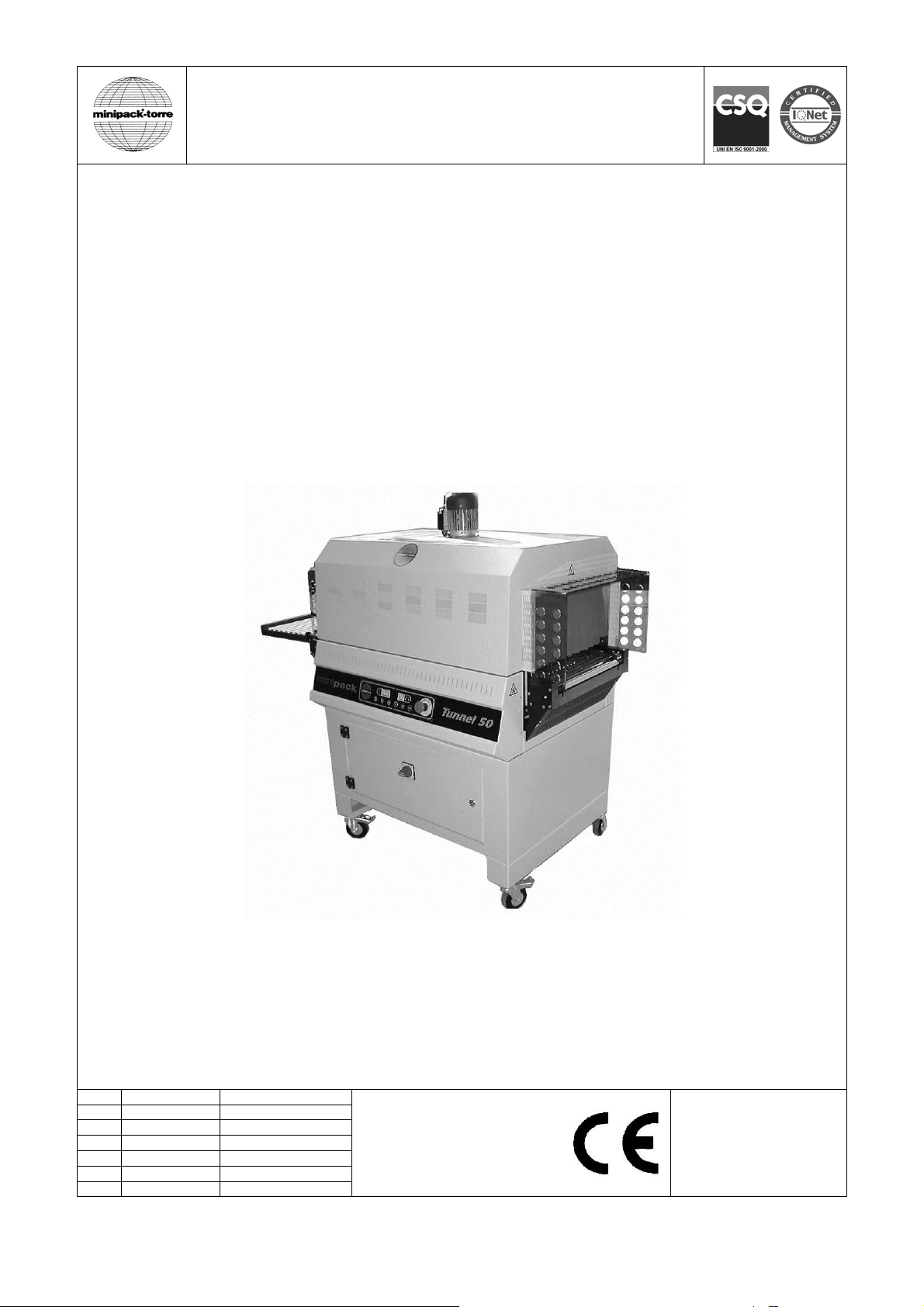
Tunnel 50 Digit
IT LEGGERE ATTENTAMENTE QUESTE ISTRUZIONI PRIMA DI USARE LA MACCHINA
EN BEFORE USING THE MACHINE PLEASE CAREFULLY READ THE INSTRUCTIONS
DE BITTE LESEN SIE DIESE ANLEITUNG GENAU DURCH, BEVOR SIE DIE MASCHINE BENÜTZEN
FR PRIERE DE LIRE ATTENTIVEMENT CE MANUEL D’INSTRUCTIONS AVANT D’UTILISER LA MACHINE
ES LEER ATENTAMENTE ESTE MANUAL ANTES DE USAR LA MÁQUINA
PT ANTES DE USAR A MÁQUINA LER CUIDADOSAMENTE ESTE MANUAL
EL ∆ΙΑΒΑΣΤΕ ΜΕ ΠΡΟΣΟΧΗ ΤΙΣ ΠΑΡΑΚΑΤΩ Ο∆ΗΓΙΕΣ ΧΡΗΣΕΩΣ ΠΡΙΝ ΧΡΗΣΙΜΟΠΟΙΗΣΕΤΕ ΤΗ ΣΥΣΚΕΥΗ
IT
Italiano Pagina 01
DOC. N. FM111070
REV. 03
ED. 01.2014
EN
English Page 13
DE
Deutsch Seite 25
FR
Français Page 37
ES
Español Página 49
PT
Português Página 61
EL
Ελληνικά Σελίδα 73

1
ISTRUZIONI ORIGINALI
Indice IT
Capitolo 1. Descrizione
1.1. Prefazione pagina 02
1.2. Caratteristiche della macchina pagina 02
1.3. Dati tecnici della macchina pagina 03
Capitolo 3. Condizioni d’uso della macchina
3.1. Dimensioni e peso max. della confezione pagina 04
3.2. Condizioni operative della macchina pagina 04
3.3. Ciò che si può confezionare pagina 04
3.4. Ciò che non si deve confezionare pagina 04
Capitolo 4. Norme di sicurezza
4.1. Avvertimenti pagina 05
4.2. Dispositivi di protezione individuale pagina 05
Capitolo 5. Installazione della macchina
5.1. Trasporto e posizionamento pagina 06
5.2. Condizioni ambientali pagina 06
5.3. Posizionamento con confezionatrice automatica, angolare, flow pack, ecc. pagina 07
5.4. Collegamento elettrico pagina 07
Capitolo 6. Regolazione ed approntamento macchina
6.1. Controllo senso di rotazione (riservato al personale di assistenza) pagina 07
6.2. Regolazione pagina 08
6.2.1. Pannello comandi pagina 08
6.2.2. Accensione della macchina pagina 08
6.2.3. Selezione programmi e taratura variabili pagina 08
6.2.4. Spegnimento della macchina pagina 08
6.2.5. Messaggi di allarme pagina 09
6.3. Regolazione del flusso d’aria pagina 09
6.4. Regolazione nastro trasportatore pagina 10
6.5. Confezionamento pagina 10
Capitolo 7. Manutenzione ordinaria
7.1. Cautele per interventi di manutenzione ordinaria pagina 11
7.2. Lubrificazione pagina 11
7.3. Rimozione di sfridi di film plastico e vari pagina 11
7.4. Pulizia della macchina pagina 11
7.5. Sostituzione del cavo di alimentazione pagina 11
7.6. Schema elettrico pagina 11
7.7. Smontaggio, demolizione e smaltimento residui pagina 12
Capitolo 8. Garanzia
8.1. Certificato di garanzia pagina 12
8.2. Condizioni di garanzia pagina 12
Dichiarazione CE di conformità
pagina 85

2
Capitolo 1. Descrizione IT
1.1. Prefazione
Il presente manuale è redatto nel rispetto della norma UNI 10893 del Luglio 2000. È rivolto a tutti gli utilizzatori al fine di
consentire un corretto uso della macchina. Conservarlo in luogo facilmente accessibile vicino alla macchina e noto a tutti
gli utilizzatori. Il presente manuale è parte integrante della macchina ai fini della sicurezza.
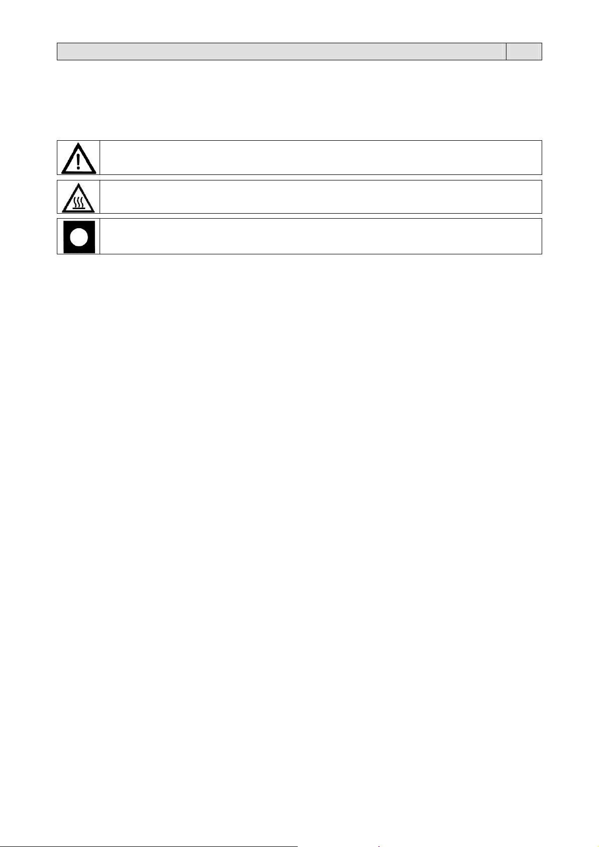
Per migliorare la comprensione precisiamo di seguito i simboli utilizzati.
ATTENZIONE:
Norme antinfortunistiche per l’operatore. Tale avvertimento indica la presenza di pericoli che
possono causare lesioni a chi sta operando sulla macchina.
ATTENZIONE:
Organi caldi. Indica il pericolo di ustioni con rischio di infortunio, anche grave per la persona
esposta.
AVVERTENZA:
Indica la possibilità di arrecare danno alla macchina e/o ai suoi componenti.
Tutti i diritti di riproduzione del presente manuale sono riservati alla ditta costruttrice. La riproduzione, anche parziale, è
vietata a termini di legge. Le descrizioni e le illustrazioni presenti in questo manuale non sono impegnative, di
conseguenza la ditta costruttrice si riserva il diritto di apportare in qualsiasi momento tutte le modifiche che riterrà
opportune. Il presente manuale non può essere ceduto in visione a terzi senza autorizzazione scritta della ditta
costruttrice. La macchina deve essere utilizzata solo per soddisfare le esigenze per cui è stata concepita, ogni altro uso è
da considerarsi “uso improprio”, quindi pericoloso.
Prima di compiere qualsiasi operazione sulla macchina è obbligatorio leggere attentamente tutte le istruzioni del presente
manuale, al fine di evitare possibili danneggiamenti alla macchina stessa, alle persone ed alle cose.
Non è consentito operare in caso di dubbi sulla corretta interpretazione delle istruzioni.
Interpellare il fabbricante per ottenere i necessari chiarimenti.
La macchina non è destinata a essere usata da persone (bambini compresi) le cui capacità fisiche, sensoriali o mentali
siano ridotte, oppure con mancanza di esperienza o di conoscenza, a meno che esse abbiano potuto beneficiare,
attraverso l’intermediazione di una persona responsabile della loro sicurezza, di una sorveglianza o di istruzioni
riguardanti l’uso dell’apparecchio.
I bambini devono essere sorvegliati per sincerarsi che non giochino con la macchina.
Al momento della consegna verificare che la macchina sia completa in tutte le sue parti.
Eventuali anomalie dovranno essere presentate immediatamente al fornitore.
La ditta costruttrice declina ogni responsabilità per uso improprio della macchina e/o per danni causati in seguito ad
operazioni non contemplate in questo manuale.
1.2. Caratteristiche della macchina
Avete acquistato una macchina dalle caratteristiche e prestazioni eccezionali e Vi ringraziamo per la preferenza
accordataci. Il sistema di confezionamento è unico nel suo genere e si è affermato nel mondo con la presenza di oltre
150000 macchine operanti nel campo dell’imballaggio e del confezionamento.
La validità del concetto tecnologico oltre che la qualità dei componenti e materiali impiegati nel processo produttivo e di
collaudo sono la migliore garanzia di un buon funzionamento e affidabilità nel tempo.
Il “Tunnel 50 Digit” è stato progettato per la termoretrazione di prodotti in uscita da confezionatrici automatiche, angolari,
flow pack, o di altro tipo.
Dispone di un particolare sistema di distribuzione dell’aria calda, prodotta da 3 resistenze, che assicura una elevata
capacità di termoretrazione, oltre ad un considerevole risparmio energetico.
Le regolazioni della velocità del nastro trasportatore e della temperatura all’interno del tunnel di retrazione sono regolate
da un pannello comandi di facile utilizzo.
3
Capitolo 1. Descrizione IT
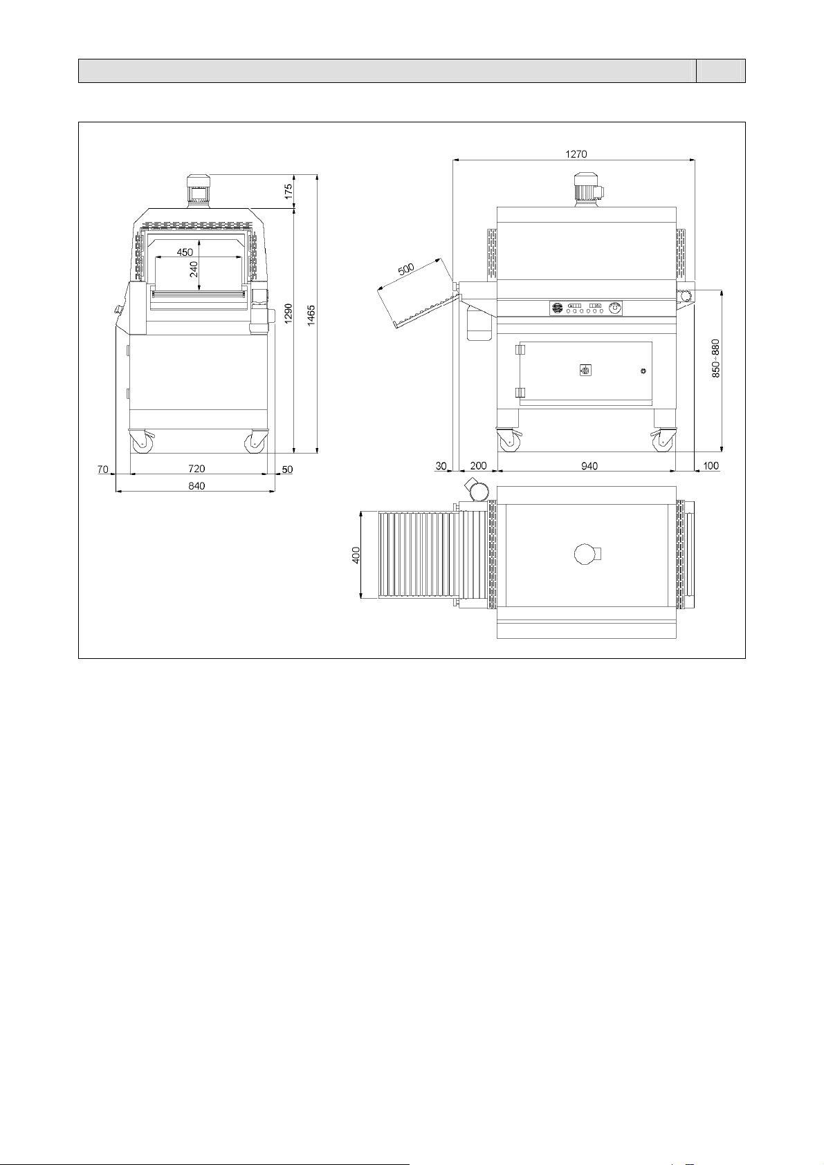
1.3. Dati tecnici della macchina
Dimensioni dell’imballo
1390 x 910 x 1640mm
Peso dell’imballo
193Kg
Peso della macchina
163Kg
4
Capitolo 3. Condizioni d’uso della macchina IT
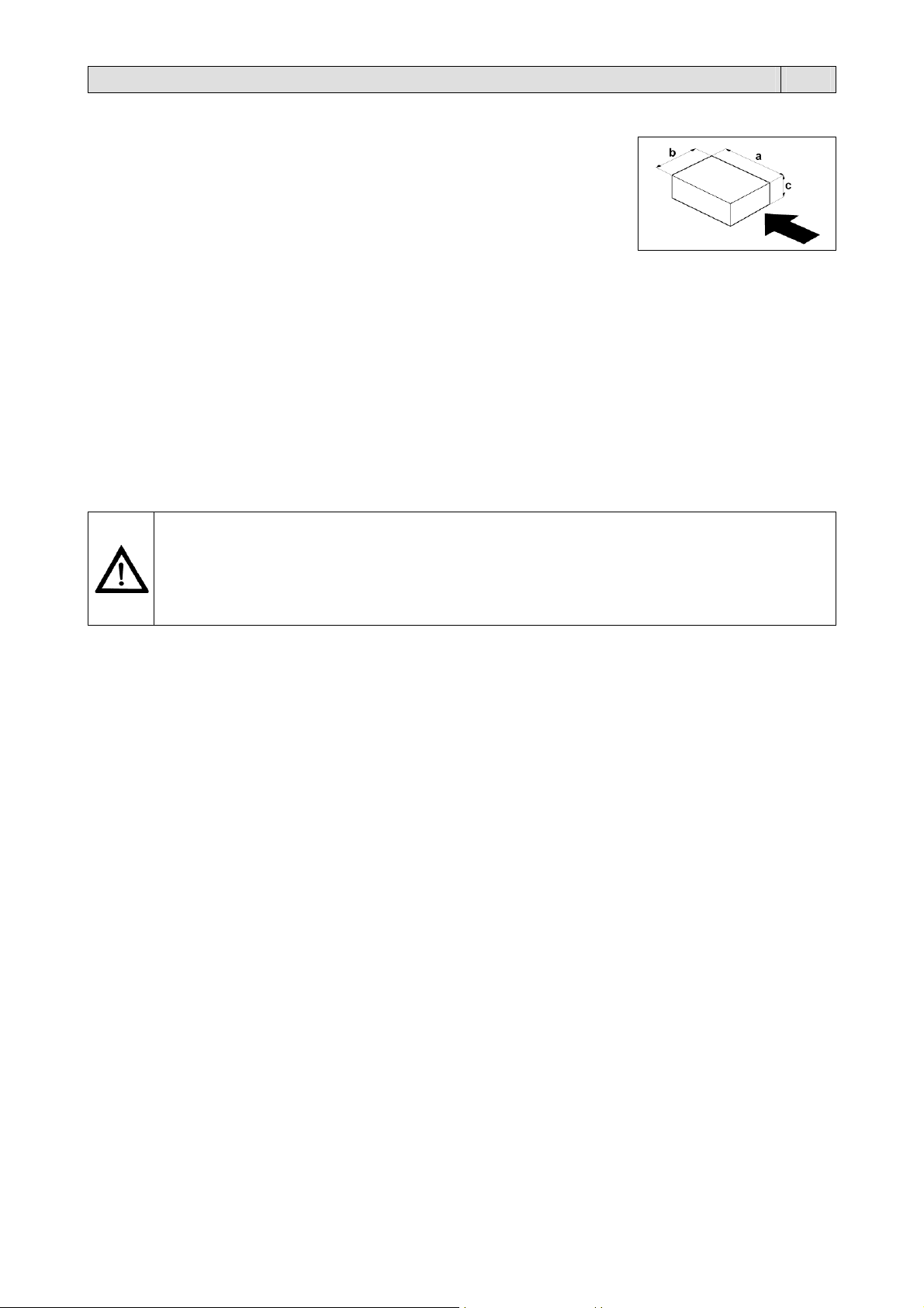
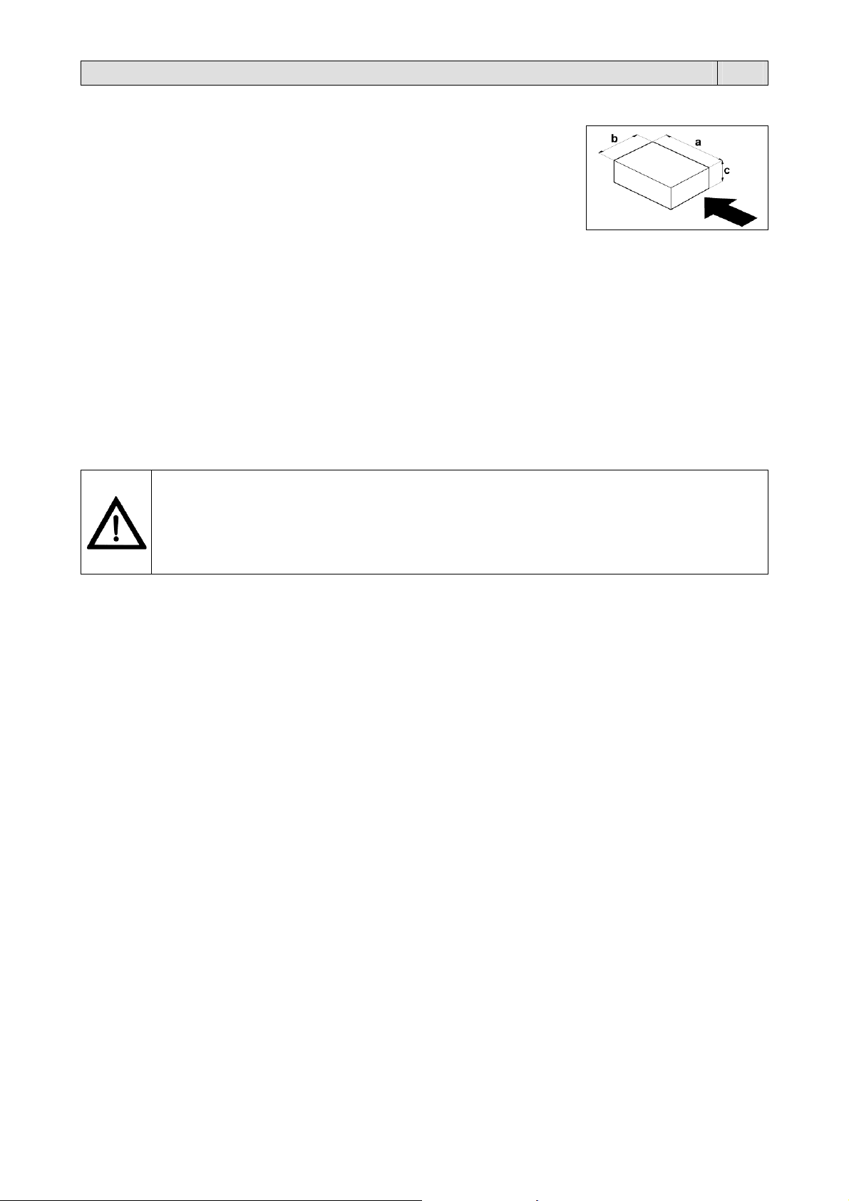
3.1. Dimensioni e peso max. della confezione
a = 740mm
b = 380mm
c = 220mm
Peso max.= 60Kg
N.B.: Il peso da considerare é quello complessivo distribuito sul nastro e non quello del
singolo pacco.
3.2. Condizioni operative della macchina
Non eseguire confezioni di dimensioni uguali o maggiori al passaggio del tunnel.
Lasciare almeno 5cm per lato.
Non eseguire confezioni di dimensioni inferiori al passo delle astine del nastro trasportatore.
La caduta del prodotto tra le astine potrebbe causare notevoli danni al nastro stesso.
3.3. Ciò che si può confezionare
Queste macchine sono in grado di confezionare una vasta gamma di prodotti completamente diversi tra loro, infatti sono
utilizzate con successo nei seguenti settori: alimentare, commercio, grafico e mailing, grande distribuzione, industria,
tessile.
3.4. Ciò che non si deve confezionare
E’ assolutamente vietato confezionare i seguenti tipi di prodotti per evitare di danneggiare in modo permanente la
macchina, oltre che provocare rischi di infortuni all’operatore addetto:
Prodotti bagnati e instabili
Liquidi di qualsiasi tipo e densità in contenitori fragili
Materiali infiammabili ed esplosivi
Bombolette con gas a pressione o di qualsiasi tipo
Polveri sciolte e volatili
Eventuali materiali e prodotti non previsti che possano in qualche modo essere pericolosi per l’utente e
provocare danni alla macchina stessa.
5
Capitolo 4. Norme di sicurezza IT
4.1. Avvertimenti
NON PERMETTERE L’USO DELLA MACCHINA A PERSONALE NON ADDESTRATO!
Pericolo di folgorazione!
Rischio dovuto all’energia elettrica presente nell’impianto elettrico posto all’interno del pannello frontale.
In caso di apertura del pannello è necessario spegnere la macchina e scollegare la spina del cavo di
alimentazione dalla presa di corrente del circuito generale.
Durante il funzionamento della macchina il pannello frontale deve essere correttamente montato.
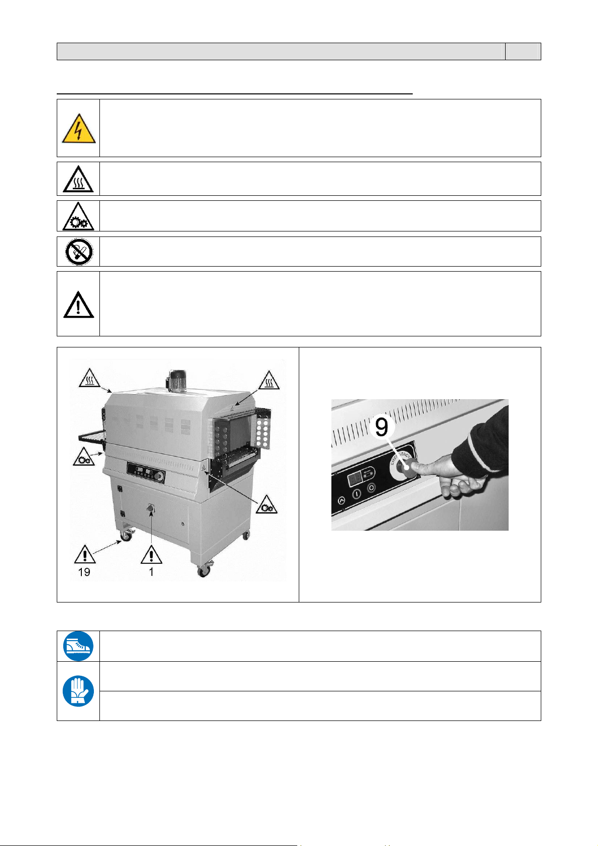
Durante le fasi di lavoro porre attenzione a tutte le parti calde della macchina che possono
raggiungere temperature tali da provocare ustioni!
Non toccare il nastro trasportatore quando è in movimento!
Durante il funzionamento della macchina è vietato fumare!
In caso di blocco della macchina o per fermarla durante il ciclo di lavoro premere il PULSANTE DI
EMERGENZA (9).
Le ruote (19) devono essere utilizzate esclusivamente per “brevi” spostamenti su pavimenti lisci
e orizzontali.
In caso di allontanamento dell’operatore dalla macchina, spegnere la macchina mettendo
l’interruttore generale (1) nella posizione “0” (OFF)!
4.2. Dispositivi di protezione individuale
Utilizzare scarpe di protezione resistenti all’urto, allo schiacciamento e alla compressione del piede
durante il trasporto e lo spostamento della macchina.
Utilizzare guanti di protezione dal pericolo di schiacciamento e dai pericoli meccanici durante il trasporto e
lo spostamento della macchina.
Utilizzare guanti di protezione in base ai rischi dei materiali da confezionare (meccanici, chimici,…) che
resistano alle temperature di contatto (massimo 200°C).

6
Capitolo 5. Installazione della macchina IT
5.1. Trasporto e posizionamento
Nel trasporto e nel posizionamento della macchina si raccomanda di manovrare con molta cautela!
Prima di ogni movimentazione, assicurarsi che il mezzo di sollevamento sia idoneo a sollevare il
carico da movimentare!
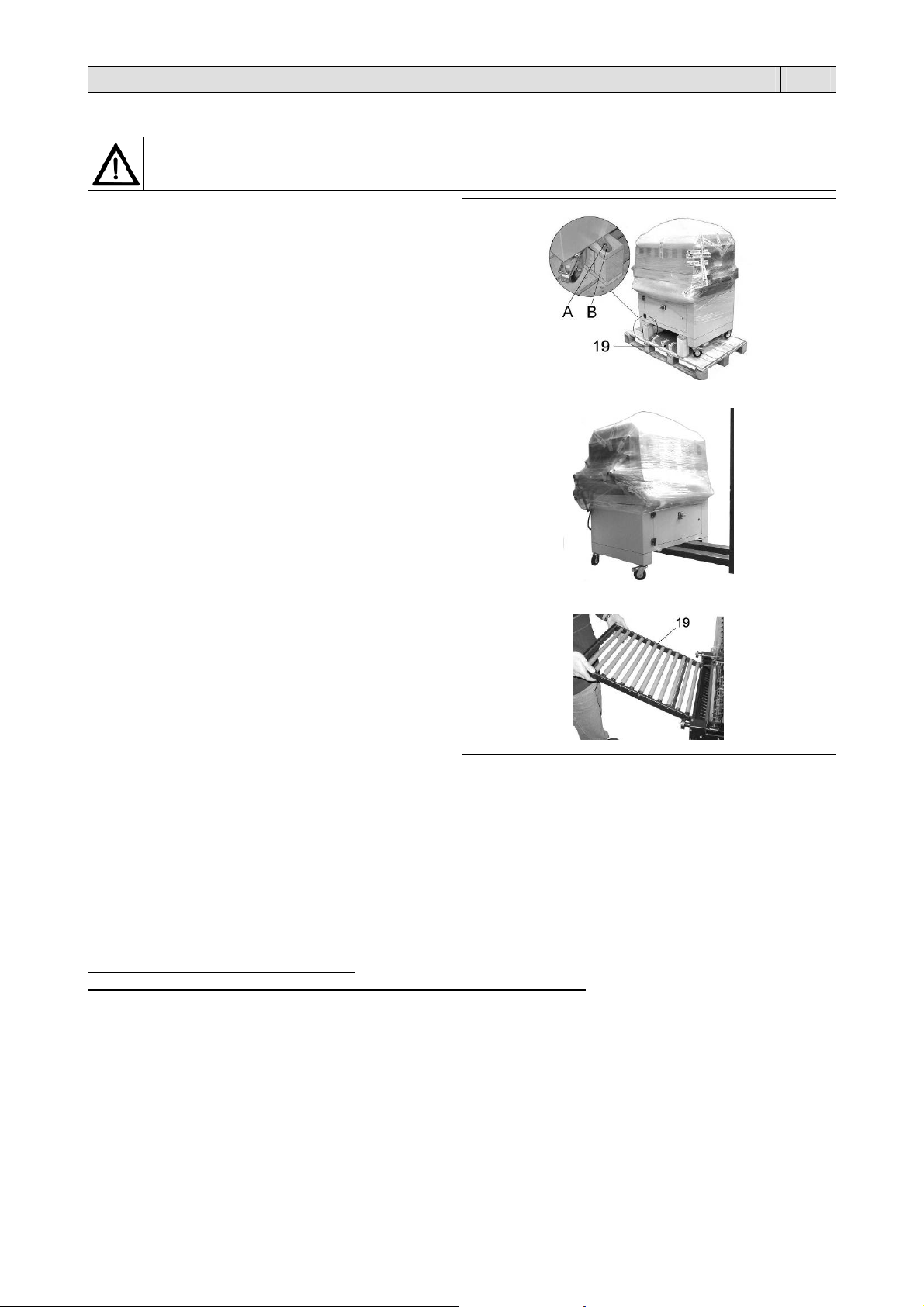
Tagliare con la forbice la reggia avendo cura di
proteggersi gli occhi con degli occhiali e sfilare il
cartone.
Togliere la rulliera (19).
Svitare le 4 viti di fissaggio (A) al pallet, riportando
all’interno della macchina le 4 piastrine (B).
Togliere il tunnel dal pallet utilizzando un carrello
elevatore a forche e posizionarlo sul pavimento.
Posizionare la rulliera (19) agganciandola al nastro
trasportatore.
5.2. Condizioni ambientali
Posizionare la macchina accertandosi che sia livellata sul pavimento, in un ambiente adatto, privo di umidità, materiali
infiammabili, gas, esplosivi. La macchina deve essere installata solamente su superfici lisci, orizzontali e non
infiammabili.
Lasciare uno spazio minimo di 0,5m attorno alla macchina, per non ostruire le prese d’aria.
Bloccare la macchina, una volta ottenuto il corretto posizionamento, agendo sul freno delle ruote.
Condizioni consentite negli ambienti in cui é collocata la macchina:
Temperatura da + 5°C a + 40°C
Umidità relativa da 30% a 90% senza condensazione.
L’illuminazione del locale di utilizzo deve essere conforme alle leggi vigenti nel paese in cui è installata la macchina e
deve comunque essere uniforme e garantire una buona visibilità, per salvaguardare la sicurezza e la salute
dell’operatore.
GRADO DI PROTEZIONE DELLA MACCHINA = IP20
IL RUMORE AEREO PRODOTTO DALLA MACCHINA È INFERIORE A 70 dB(A)

7
Capitolo 5. Installazione della macchina IT
5.3. Posizionamento con confezionatrice automatica, angolare, flow pack, ecc.
Posizionare il “Tunnel 50” in modo che il nastro del tunnel sia il più vicino possibile al nastro in uscita della
“confezionatrice”.
Il nastro del tunnel deve risultare 1mm più alto rispetto a quello della “confezionatrice”, per evitare la caduta dei prodotti
confezionati.
Posizionare il tunnel in modo che il prodotto in uscita dalla “confezionatrice” si posizioni al centro del nastro del tunnel.
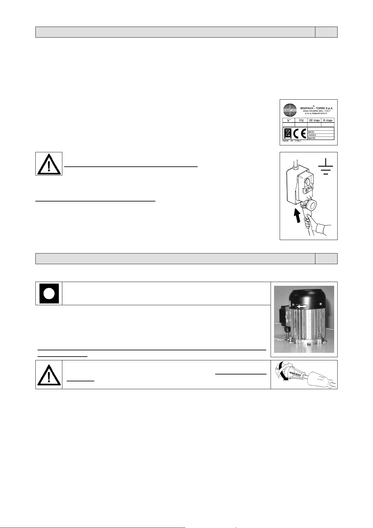
5.4. Collegamento elettrico
Tensione (V): vedere dati targhetta
Frequenza (Hz): vedere dati targhetta
Potenza massima assorbita (W): vedere dati targhetta
Corrente massima assorbita (A): vedere dati targhetta
N.B.: Per qualsiasi comunicazione con il costruttore, citare sempre il modello della macchina e il
numero di matricola indicati sulla targhetta applicata nella parte posteriore della macchina.
RISPETTARE LE NORME PER LA SICUREZZA SUL LAVORO!
Se la macchina non è dotata della spina di alimentazione utilizzare una spina adeguata ai valori
di tensione e amperaggio descritti nella targhetta dati e comunque conforme alle normative
vigenti nel paese d’installazione.
È OBBLIGATORIA LA MESSA A TERRA!
Prima di effettuare il collegamento elettrico assicuratevi che la tensione di rete corrisponda al
voltaggio indicato sulla targhetta applicata nella parte posteriore della macchina e che il contatto
di terra sia conforme alle norme di sicurezza vigenti. In caso di dubbi sulla tensione di rete
contattate l’ente locale distributore dell’energia elettrica.
Collegare la spina del cavo proveniente dal quadro elettrico della macchina in una presa di
corrente del circuito generale che sia facilmente raggiungibile dall’operatore.
Capitolo 6. Regolazione ed approntamento macchina IT
6.1. Controllo senso di rotazione (riservato al personale di assistenza)
Prima di mettere in funzione la macchina verificarne l’esatto senso di
rotazione seguendo queste istruzioni:
1. Collegare il cavo di alimentazione ad una presa trifase più terra.
2. Ruotare l’interruttore generale (1) sulla posizione 1.
3. Premere il pulsante di START (5).
4. Controllare che il senso di rotazione della ventola del motore (M1) corrisponda al senso
indicato dalla freccia.
N.B.: Il controllo del senso di rotazione va eseguito ogni volta che si cambia presa di
alimentazione.
Se il senso di rotazione è contrario, si deve TOGLIERE TENSIONE ALLA
MACCHINA ed invertire due delle tre fasi della spina di alimentazione.
8
Capitolo 6. Regolazione ed approntamento macchina IT
6.2. Regolazione
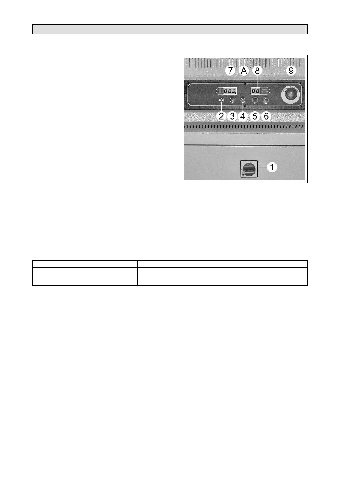
6.2.1. Pannello comandi
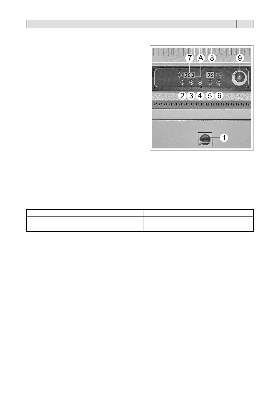
La macchina è dotata di un pannello di comando, dal quale è
possibile impostare tutte le funzioni di programmazione e
funzionamento.
1. Interruttore generale
2. Pulsante di selezione variabili
3. Pulsante “DECREMENTA”. Riduce i valori delle funzioni
impostate
4. Pulsante “INCREMENTA”. Aumenta i valori delle
funzioni impostate
5. Pulsante START
6. Pulsante STOP
7. Display temperatura
8. Display nastro
9. Pulsante di EMERGENZA. Se premuto, arresta
immediatamente la macchina in caso di pericolo
immediato.
6.2.2. Accensione della macchina
Ruotare l’interruttore generale (1) nella posizione 1.
Il display (8) si accende e compare il n° di programma attivo.
Premere il pulsante di START (5).
Prima di usare la macchina attendere che arrivi alla temperatura impostata segnalata dallo spegnimento della spia (A).
Premendo il pulsante (6) compare il numero di programma attivo.
6.2.3. Selezione programmi e taratura variabili
La macchina ha 9 programmi selezionabili (P1 ÷ P9).
Ogni programma è composto da 2 variabili modificabili.
Variabile Campo Caratteristiche Campo
1. Temperatura tunnel
2. Velocità nastro tunnel
000 ÷ 230.
00 ÷ 99.
Valori espressi in °C.
Valori espressi in percentuale:
00: velocità minima; 99: velocità massima
Per selezionare il n° di programma (P1 ÷ P9) premere i pulsanti (3) e (4).
Con il pulsante (2) si entra nel programma visualizzato.
Con il pulsante (2) si scorrono le variabili del programma scelto e con i pulsanti (3) e (4) si modificano i valori
memorizzati. Per convalidare le modifiche premere il pulsante (2).
6.2.4. Spegnimento della macchina
Premere il pulsante di STOP (6). Con questo pulsante si effettua lo spegnimento temporizzato del tunnel (si spengono le
resistenze, il nastro gira alla minima velocità, ma la ventola continua a funzionare per circa 3-4 minuti, in modo da
permettere il raffreddamento del tunnel stesso).
Quando la ventola e il nastro si fermano ruotare l’interruttore generale (1) nella posizione 0.
9
Capitolo 6. Regolazione ed approntamento macchina IT
6.2.5. Messaggi d’allarme
La scheda elettronica prevede la rilevazione di alcuni allarmi che vengono segnalati tramite la visualizzazione sul display
(7) dei seguenti messaggi:
A 1
Allarme “Pulsante di Emergenza”.
Il pulsante di emergenza (9) è premuto.
Sboccare il pulsante ruotandolo verso destra, e successivamente premere il pulsante di START (5).
A 2
Allarme “Inverter”.
Verificare sul display dell’inverter posto nell’impianto elettrico, la codifica dell’anomalia e controllare sul
manuale utente dell’inverter (in dotazione con la macchina) le modalità per il ripristino.
A 3
Allarme “termico motori”.
Verificare il corretto funzionamento del motore della ventola.
A 4
Allarme “temperatura”.
La temperatura ha superato i 230°C oppure la sonda è interrotta.
Verificare la sonda e i relativi collegamenti.
Se dopo avere effettuato gli interventi e i controlli indicati per il ripristino della macchina, l’allarme
rimane, contattare l’assistenza tecnica.
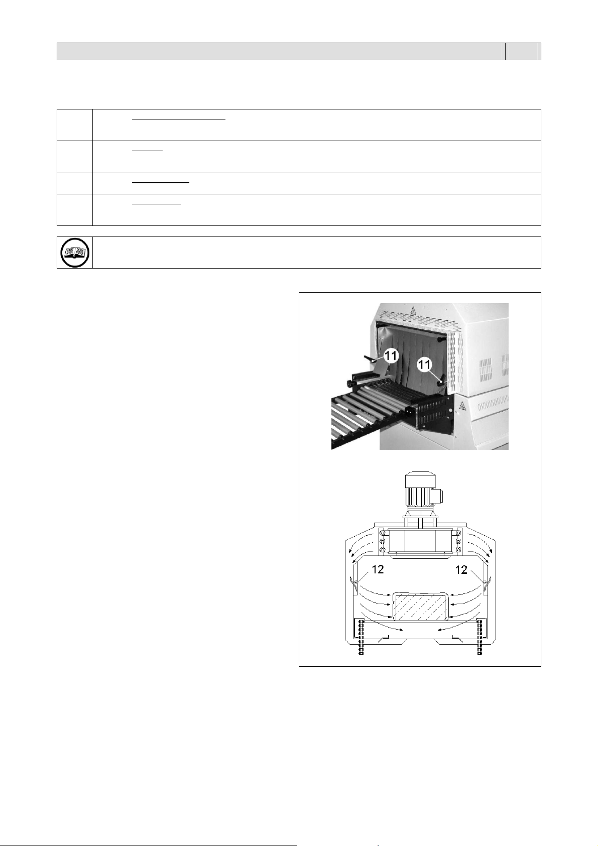
6.3. Regolazione del flusso d’aria
È possibile regolare il flusso dell’aria calda sul prodotto da
confezionare agendo sulle manopole (11).
La rotazione delle manopole (11) determina la posizione
dei deflettori (12), che dirigono il flusso dell’aria calda nella
direzione voluta per ottenere la migliore retrazione.
1
0
Capitolo 6. Regolazione ed approntamento macchina IT
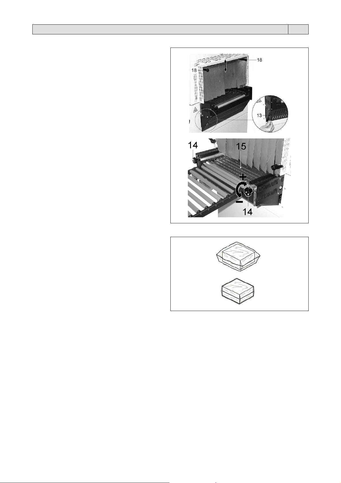
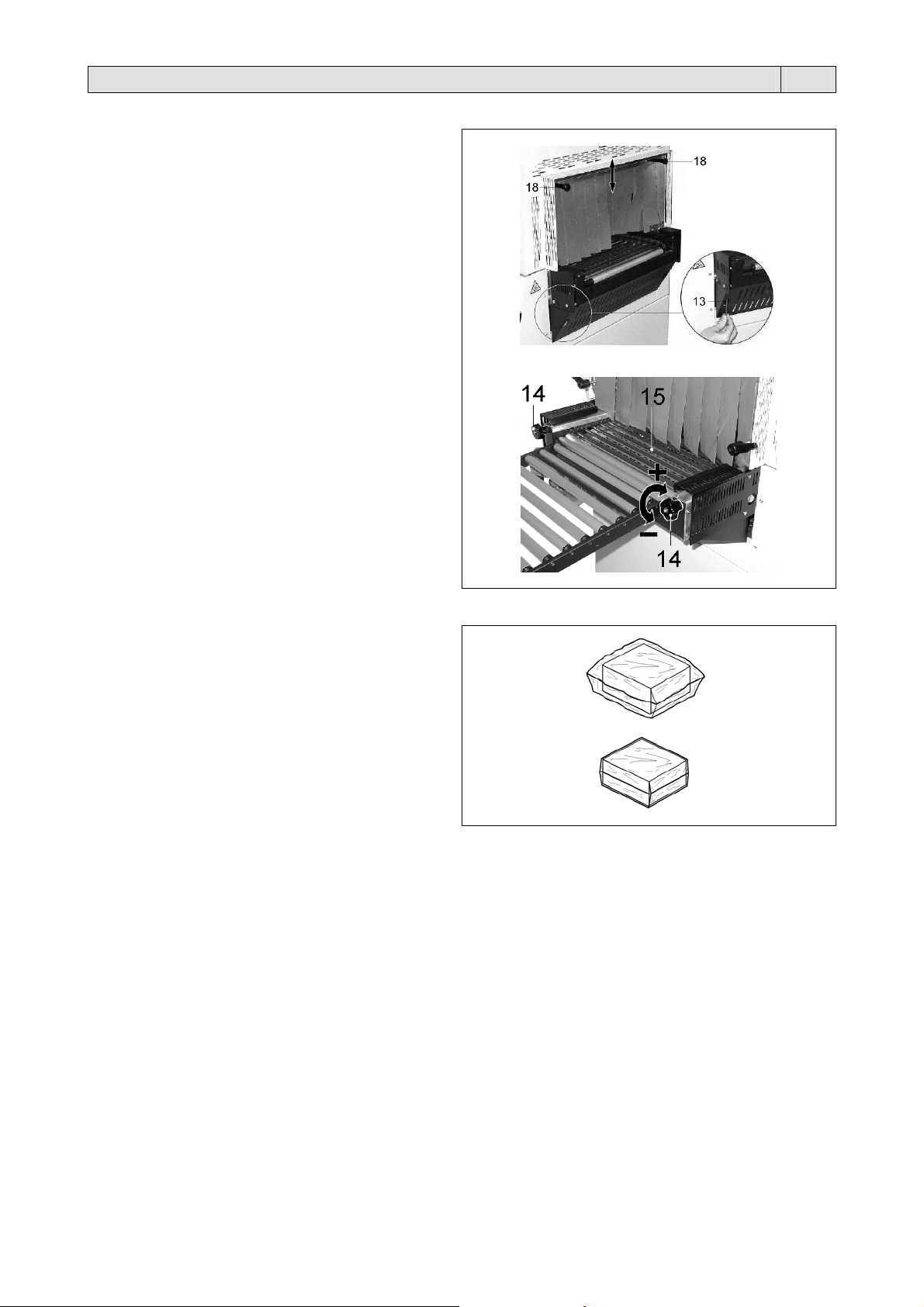
6.4. Regolazione nastro trasportatore
Regolare l’altezza del nastro trasportatore agendo sulle
apposite viti (13).
Regolare le tendine all’ ingresso del tunnel agendo sulle
apposite manopole (18) in modo che le stesse siano a
livello del nastro del tunnel.
Mediante la regolazione dei volantini (14) posti sulle spalle
del nastro trasportatore é possibile fare in modo che i
rullini (15) del nastro, ruotino o siano folli.
Ruotando i volantini in senso orario (+) i rullini (15) non
girano.
Ruotando i volantini in senso antiorario (-) i rullini (15)
girano.
N.B.: Questa regolazione va eseguita solo con il
nastro trasportatore in movimento.
6.5 Confezionamento
Eseguite tutte le regolazioni la macchina é pronta per
procedere al confezionamento.
Premere il pulsante START (5).
Il nastro entra in funzione ed è possibile iniziare a caricare
i prodotti sul nastro stesso.
Il prodotto, racchiuso in un sacchetto floscio (figura A),
entra nel tunnel di retrazione, dove la circolazione di aria
calda favorisce la termoretrazione del film.
A
ll’uscita del tunnel il prodotto confezionato è racchiuso in
un sacchetto che aderisce perfettamente alla sua forma
(figura B).
figura (A)
figura (B)
11
Capitolo 7. Manutenzione ordinaria IT
7.1. Cautele per interventi di manutenzione ordinaria
LA MANUTENZIONE ORDINARIA DEVE ESSERE EFFETTUATA DA PERSONALE QUALIFICATO
OPPORTUNAMENTE ISTRUITO.
Prima di effettuare le operazioni di manutenzione spegnere la macchina agendo sull’interruttore
generale, togliere la spina dalla presa di rete e attendere il raffreddamento della macchina!
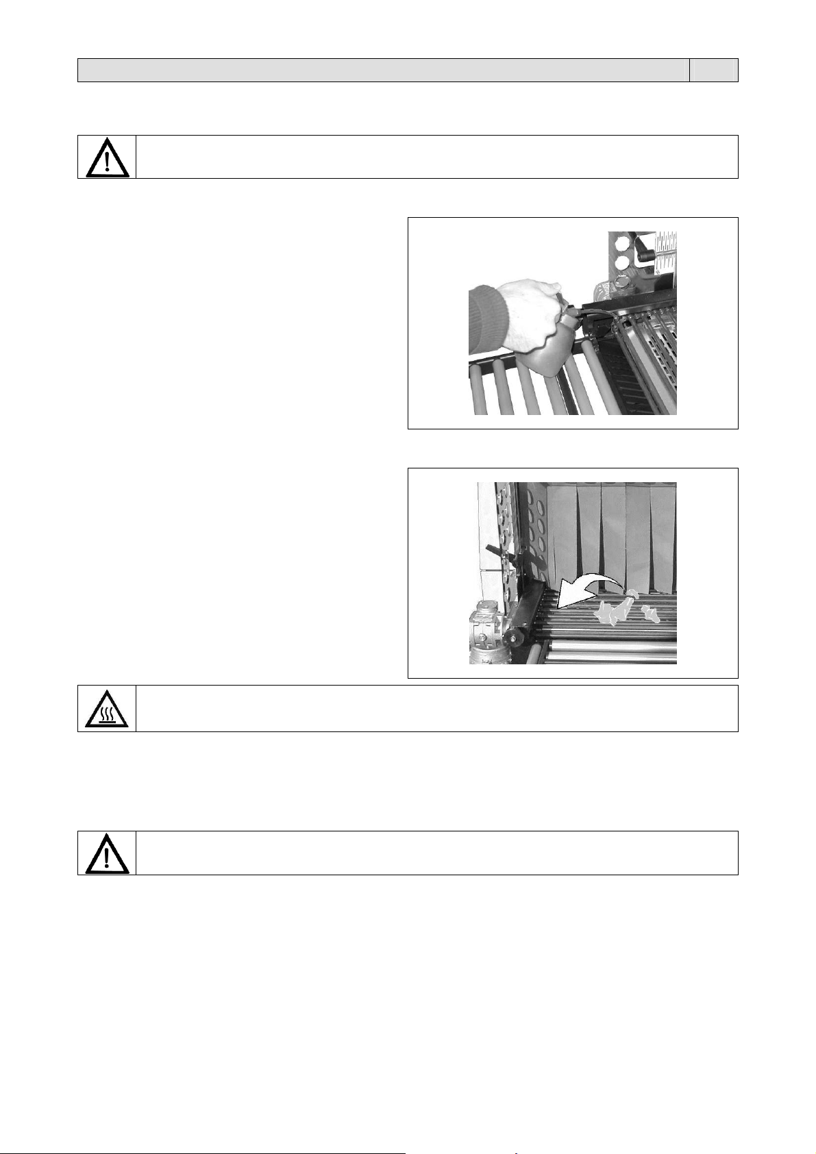
7.2. Lubrificazione
Lubrificare periodicamente le catene del nastro
trasportatore utilizzando lubrificante per alta temperatura,
es:
grasso siliconico
grasso infusibile
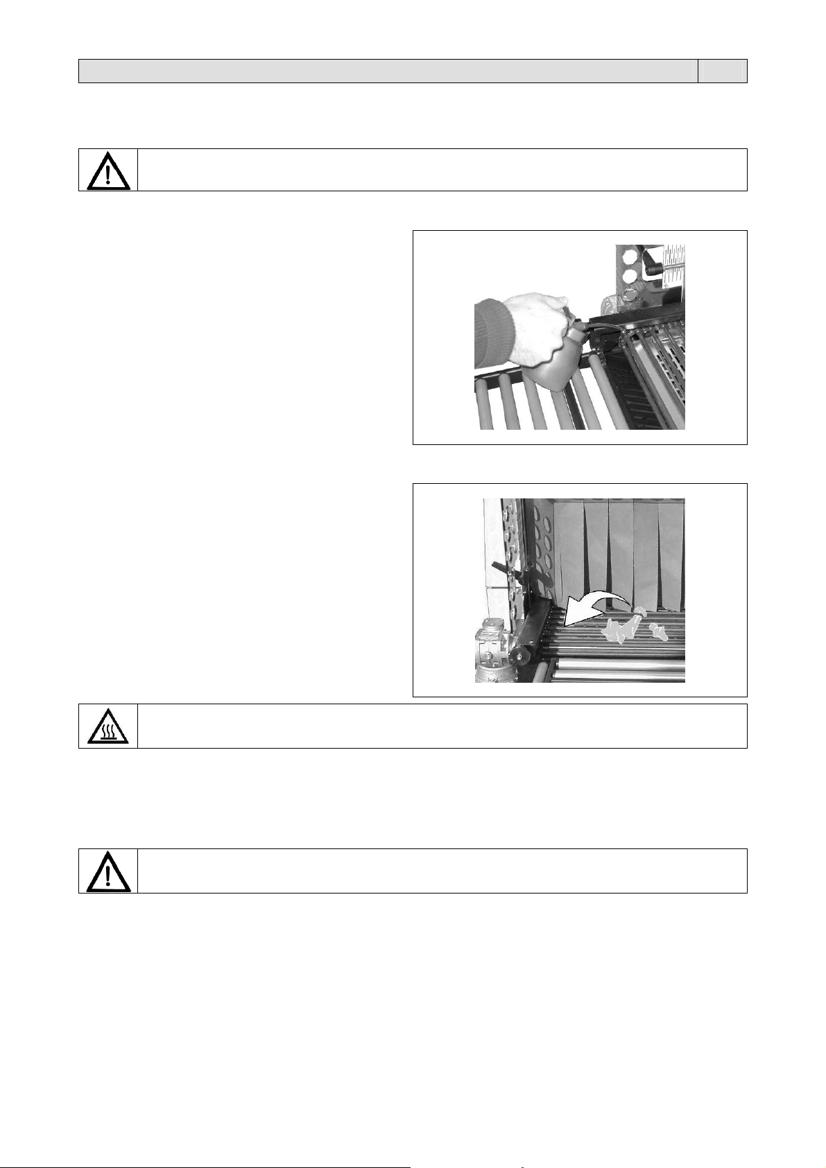
7.3. Rimozione di sfridi di film plastico e vari
È molto importante provvedere con frequenza alla pulizia
interna del tunnel, in modo da asportare tutti i residui di
film dei prodotti confezionati.
Prima di eseguire questa operazione, attendere che il tunnel si sia adeguatamente raffreddato!
7.4. Pulizia della macchina
Per la pulizia del tunnel utilizzare un panno inumidito con acqua.Per nessun motivo utilizzare solventi, ma normali
detergenti.
7.5. Sostituzione del cavo di alimentazione
ATTENZIONE!
Se il cavo di alimentazione è danneggiato, esso deve essere sostituito dal costruttore o dal suo servizio
assistenza tecnica, o comunque da una persona con qualifica similare, in modo da prevenire ogni rischio.
7.6. Schema elettrico (pagine 86/87).
BT1 Termocoppia M1 Motore ventola 1
ER1 Resistore 1 M2 Motore nastro
ER2 Resistore 1 Q1 Interruttore generale
ER3 Resistore 1 QM0 Contattore inverter
F0 Fusibile ausiliari QM1 Contattore motore ventola
F1 Fusibili trasformatore ausiliari QM2 Contattore resistori 1
F2 Fusibili inverter S0 Pulsante emergenza
F3 Fusibili motori ventole SK1 Scheda comando
F4 Fusibili resistori 1 T1 Trasformatore ausiliari
FU2 Fusibile scheda TS1 Inverter
FM1 Termico motore ventola 1

12
Capitolo 7. Manutenzione ordinaria IT
7.7. Smontaggio, demolizione e smaltimento residui
ATTENZIONE!
Le operazioni di smontaggio e demolizione devono essere affidate a personale specializzato a tali attività
e dotato delle competenze meccaniche ed elettriche necessarie a lavorare in condizioni di sicurezza.
Procedere nel seguente modo:
1. scollegare la macchina dalla rete di alimentazione elettrica
2. smontare i componenti
Ciascun rifiuto deve essere trattato, smaltito o riciclato in base alla classificazione ed alle procedure previste
dalla legislazione vigente nel paese di installazione.
Il simbolo indica che questo prodotto non deve essere trattato come rifiuto domestico. Assicurando che il
prodotto venga correttamente eliminato, si faciliterà la prevenzione di potenziali conseguenze negative
per l’ambiente e la salute dell’uomo, che potrebbero altrimenti essere causate da un inappropriato
trattamento del rifiuto di questo prodotto. Per informazioni più dettagliate riguardo il riciclaggio di questo
prodotto, contattare il venditore del prodotto, o in alternativa il servizio di post vendita o l’appropriato
servizio di trattamento dei rifiuti.
Capitolo 8. Garanzia IT
8.1. Certificato di garanzia
La Garanzia ha validità 12 mesi dalla data di installazione alle condizioni riportate sul libretto d’istruzioni. Compilare il
retro della cartolina in ogni sua parte, strappare lungo la linea e spedire.
8.2. Condizioni di garanzia
La garanzia è valida 12 mesi e decorre dalla data di installazione della macchina. La garanzia consiste nella sostituzione
o riparazione gratuita di tutte quelle parti riscontrate da noi difettose per anomalie di materiali. Le riparazioni o sostituzioni
avvengono normalmente presso la casa costruttrice con l’addebito all’acquirente delle spese di trasporto o manodopera.
Qualora le riparazioni o sostituzioni vengano eseguite presso la sede dell’acquirente, quest’ultimo sarà tenuto a pagare
le spese di viaggio, trasferta e manodopera. Le prestazioni di garanzia vengono eseguite esclusivamente a cura della
casa costruttrice o dal rivenditore autorizzato. Per avere diritto a prestazioni di garanzia inviare alla casa costruttrice od al
rivenditore autorizzato il pezzo difettoso, perché sia effettuata la riparazione o sostituzione. La riconsegna di tale pezzo
riparato o sostituito, rien trerà nell’adempimento delle operazioni di garanzia. La garanzia viene annullata:
1. per il mancato immediato invio postale del CERTIFICATO DI GARANZIA al momento dell’acquisto, debitamente
compilato e firmato entro 20 giorni.
2. per la errata installazione, la inadeguata alimentazione, negligenza d’uso e manomissione da parte di persone non
autorizzate.
3. per modifiche effettuate sulla macchina senza il consenso scritto della casa.
4. qualora la macchina non sia più proprietà del primo acquirente
La casa costruttrice declina a termine di legge ogni responsabilità per danni a persone o cose qualora venga
effettuata un’errata installazione o collegamento alla rete di alimentazione elettrica o esclusione della messa a
terra od in caso di manomissioni della macchina stessa. La casa costruttrice si riserva di approntare modifiche
e cambiamenti secondo esigenze tecniche e di funzionamento
PER QUALUNQUE CONTROVERSIA LEGALE
IL FORO COMPETENTE È QUELLO DI BERGAMO (ITALIA).

13
TRANSLATION OF THE
ORIGINAL INSTRUCTIONS
Contents EN
Chapter 1. Description
1.1. Preface page 14
1.2. Machine features page 14
1.3. Machine technical data page 15
Chapter 3. Machine usage conditions
3.1. Max. weight and dimensions of the package page 16
3.2. Machine operating conditions page 16
3.3. Items that may be packaged page 16
3.4. Items which must not be packed page 16
Chapter 4. Safety standards
4.1. Warnings page 17
4.2. Individual protection devices page 17
Chapter 5. Machine installation
5.1. Transport and positioning page 18
5.2. Environmental conditions page 18
5.3. Positioning with automatic, angular, flow pack, etc. packaging machine page 19
5.4. Electrical connections page 19
Chapter 6. Machine adjustment and setting up
6.1. Direction of rotation check (reserved to the assistance personel) page 19
6.2. Adjustment page 20
6.2.1. Control panel page 20
6.2.2. Switching the machine on page 20
6.2.3. Program selection and variable setting page 20
6.2.4. Switching machine off page 20
6.2.5. Alarm messages page 21
6.3. Air flow adjustment page 21
6.4. Conveyor belt adjustment page 22
6.5. Packaging page 22
Chapter 7. Ordinary maintenance
7.1. Instructions for ordinary maintenance work page 23
7.2. Lubrication page 23
7.3. Plastic film and other scrap removal page 23
7.4. Machine cleaning page 23
7.5. Replacement of the supply cord page 23
7.6. Wiring diagram page 23
7.7. Disassembling, demolition and elimination of residuals page 24
Chapter 8. Guarantee
8.1. Certificate of guarantee page 24
8.2. Guarantee conditions page 24
CE declaration of conformity page 85

14
Chapter 1. Description EN
1.1. Preface
This manual has been drawn up in compliance with the UNI10893 standard dated July 2000. It is meant for all users in
order to enable them to use the machine correctly. Keep it in a place which can be easily accessed in the proximity of the
machine and which is known to all users. This manual is an integral part of the machine for safety reasons. We wish to
specify the symbols in use here below in order to improve understanding of them.
ATTENTION:
Accident prevention rules for the operator. This warning indicates the presence of dangers which
can injure the person operating on the machine.
ATTENTION:
Hot parts. Shows the danger of burning, thus involving the risk of a serious accident for the exposed
person.
WARNING:
It indicates the possibility of damaging the machine and/or its components.
All reproduction rights of this manual are reserved to the manufacturer. Partial or complete reproduction is forbidden as
provided by the law. Descriptions and pictures provided in this manual are not binding. Therefore the manufacturer,
reserves the right to make any change considered necessary. This manual cannot be transferred for viewing to third
parties without authorisation in writing from the manufacturing company. The machine must be used only for the purpose
it was built for. Any other use shall be considered “improper” and therefore dangerous. Before carrying out any operation
on the machine it is compulsory to read carefully all instructions provided in this manual, in order to avoid possible
damage to the machine, to people and property.
Do not operate if in doubt about the correct interpretation of the instructions.
Contact the manufacturer in order to obtain the necessary explanation.
This machine is not intended for use by persons (including children) with reduced physical, sensory or mental
capabilities, or lack experience and knowledge, unless they have been given supervision or instruction concerning use of
the machine by a person responsible for their safety.
Children should be supervised to ensure that they do not play with the machine.
Upon delivery check that the machine is complete in all parts.
Possible faults shall be immediately reported to the manufacturer.
The manufacturing company declines any liability in case of machine improper use and/or in case of damage resulting
from operations carried out on the machine that are not mentioned in this manual.
1.2. Machine features
You have bought a machine with outstanding features and performance and we thank you very much for your confidence
in choosing it. The system is unique in its kind and has achieved worldwide success with more than 150000 units
operating in the field of packaging and wrapping.
The technological concept underlining its design, as well as the components and materials used in the manufacturing and
testing process are the best assurance of proper operation and long-lasting liability.
The “Tunnel 50 Digit” has been designed for the heat shrinking of products leaving the automatic, angular, flow pack and
other types of packaging machines.
It has a special hot air distribution system, produced by 3 resistors, which provides a high heat shrinking capacity as well
as considerable energy-saving.
Speed control of the conveyor belt and the temperature inside the shrink tunnel are adjusted by an easy to use control
panel.

1
5
Chapter 1. Description EN
1.3. Machine technical data
Package sizes
1390 x 910 x 1640mm
Package weight
193Kg
Machine weight
163Kg
1
6
Chapter 3. Machine usage conditions EN
3.1. Max. weight and dimensions of the package
a = 740mm
b = 380mm
c = 220mm
Max weight = 60Kg
NOTE: The weight to be considered is the total weight distributed on the conveyor belt,
and not the one of the single package.
3.2. Machine operating conditions
Do not makes packages as big or larger than the tunnel clearance.
Leave at least 5cm on each side.
Do not carry out packages whose dimensions are lower than the rods pitch of the conveyor belt.
The product fall between the rods could cause remarkable damages to the belt itself.
3.3. Items that may be packaged
These machines are capable of packing a wide range of completely different products.
They are used successfully in the following sectors: food, marketing, graphics and mailing, large distribution, industry,
fabrics.
3.4. Items which must not be packed
The products listed below must absolutely not be wrapped to avoid permanent damage to the machine and serious
injuries to the operator:
Wet and unstable products
Liquids of any kind and density in fragile containers
Flammable and explosive materials
Pressurised gas cylinder of any kind
Bulk and volatile powders
Any materials and products not listed but which might harm operator and cause damages to the
machine.

1
7
Chapter 4. Safety standards EN
4.1. Warnings
THE MACHINE CAN NOT BE USED BY UNTRAINED PERSONNEL!
Danger of electrocution!
Risk due to presence of electrical power in electrical system inside front panel.
When the panel is opened, the machine must be switched off and the plug must be pulled from the socket
of the main circuit.
While the machine is running, the front panel must be mounted properly.
During work pay attention to all hot parts of the machine. The temperature they can reach is so high
that it can cause burns!
Do not touch the transport belt while it is moving!
Smoking is forbidden while the machine is operating!
In case of blocking of the machine or in order to stop it during the working cycle press
EMERGENCY PUSHBUTTON (9).
The wheels (19) must be used only for moving the unit short distances across smooth, horizontal
floors.
If it is necessary to leave the machine unattended, switch it off by turning the main switch (1) to
the “0” (OFF) position!
4.2. Individual protection devices
Wear safety shoes that protect feet from impacts, crushing and compression while moving or handling the
machine.
Wear safety gloves that protect the hands from crushing and mechanical hazards and while moving or
handling the machine.
Wear safety gloves that protect the hands against the specific risks associated with the materials to be
packed (mechanical, chemical) and against coming into contact with the high temperatures present (up to
200°C).
1
8
Chapter 5. Machine installation EN
5.1. Transport and positioning
Handle with great care during transport and positioning!
Before any movement, make sure that the lifting means is suitable for the load to be lifted!
Cut the strap with scissors make sure you protect
your eyes by wearing glasses and withdraw the
cardboard.
Remove the roller plate (19).
Unscrew the 4 fastening screws (A) to the pallet,
putting the 4 plates (B) back inside the machine.
Using a fork lift, remove the tunnel from its pallet and
level it on the ground.
Position the roller plate (19), coupling it to the
conveyor belt.
5.2. Environmental conditions
Place the machine level on the floor in a suitable environment free from humidity, gases, explosives, combustible
materials. The machine may only be installed on smooth, flat non-inflammable surfaces.
Leave a minimum space of 0,5m around the machine so that not to obstruct air inlets.
Once the correct position is achieved, lock the machine by means of the wheel brakes.
Working environment conditions:
Temperature from + 5°C to + 40°C
Relative humidity from 30% to 90%, without condensation
The lighting of the operation room shall comply with the laws in force in the country where the machine is installed.
However, it shall be uniform and allow good visibility in order to safeguard the operator’s safety and health.
MACHINE PROTECTION FACTOR = IP20
THE AIRBORNE NOISE MADE BY THE MACHINE IS LOWER THAN 70 dB(A)
19
Chapter 5. Machine installation EN
5.3. Positioning with automatic, angular, flow pack, etc. packaging machine
Position the “Tunnel 50” so that the conveyor belt of the tunnel is as close to the outfeed belt of the “packaging machine”
as possible.
The tunnel conveyor belt must be 1mm higher than that of “packaging machine”, to keep packaged products from falling.
Position the tunnel so that the outfeed product from “packaging machine” is positioned at the centre of the tunnel
conveyor belt.
5.4. Electrical connections
Voltage (V): see data on plate
Frequency (Hz): see data on plate
Maximum absorbed power (W): see data on plate
Maximum absorbed current (A): see data on plate
N.B.: When contacting the Manufacturer, always indicate the model and the serial number
specified on the plate on the rear part of the machine.
OBSERVE HEALTH AND SAFETY REGULATIONS!
If the machine is not equipped with the power supply plug, use a plug that is suitable for the
voltage and amperage values described by the rating plate and that can comply with the rules in
force in the installation country.
GROUNDING OF THE UNIT IS OBLIGATORY!
Before making electrical connections, make sure the mains voltage matches the one on the
plate on machine rear and that the ground contact complies with the safety rules in force.
In case of doubts about the mains voltage, contact the local power supply company.
Insert the plug on the cable from machine electrical cabinet in a mains power supply socket that
can be reached easily by the operator.
Chapter 6. Machine adjustment and setting up EN
6.1. Direction of rotation check (reserved to the assistance personel)
Before starting machine operation check the correct direction of rotation
by following these instructions:
1. Connect the power cord to a three phase plug plus earthing.
2. Turn the main switch (1) into position 1.
3. Press START button (5).
4. Check that the rotation sense of the motor fan (M1) shown in the picture corresponds
to the sense indicated by the arrow.
N.B.: The control of direction of rotation should be carried out each time you change
the electrical plug.
In case the rotating sense is directed counterclockwise, DISCONNECT THE
MACHINE and reverse two of the three phases of the feeding plug.
2
0
Chapter 6. Machine adjustment and setting up EN
6.2. Adjustment
6.2.1. Control panel
The machine is fitted with a control panel, from which all
programming and operation functions can be set.
1. Main switch
2. Variables selection switch
3. Button “DECREASE”. Reduces set function values
4. Button “INCREASE”. Increases set function values
5. START button
6. STOP button
7. Temperature display
8. Belt display
9. EMERGENCY pushbutton. If pressed, it immediately
stops the machine in case of immediate danger.
6.2.2. Switching the machine on
Turn the main switch (1) into pos. 1.
The display (8) turns on and the number of the currently selected program will appear.
Press START button (5).
Before using the machine, wait until the adjusting temperature is reached. This is signalled by the extinction of the
warning light (A).
Press button (6) to display the active programme number.
6.2.3. Program selection and variable setting
The machine is equipped with 9 selectionable programs (P1 ÷ P9).
Each program is composed by 2 variables which can be modified.
Variable Field Field features
1. Tunnel temperature
2. Tunnel belt speed
000 ÷ 230.
00 ÷ 99.
Values expressed in °C.
Values expressed in percentage:
00: minimum speed; 99: maximum speed
Push button (3) and (4) to select the number of the program.
Press button (2) to access the programme on the display.
Through button (2) it is possible to look through the variables of the selected program, while through buttons (3) and (4)
the memorized values can be modified. To validate modifications, press button (2).
6.2.4. Switching machine off
Press STOP button (6).
Press this button to provide for the timed power off of the tunnel (resistances are powered off, the tape turns at the
minimum speed, but the fan wheel continues to work for about 3-4 minutes so as to enable the tunnel to cool down).
When the fan wheel and tape stop, turn main switch (1) and set it to 0.

21
Chapter 6. Machine adjustment and setting up EN
6.2.5. Alarm messages
The electronic board detects series of alarms that are indicated on the display (7) by the following messages:
A 1
“Emergency pushbutton” alarm.
Emergency pushbutton (9) is held down.
Release the button by turning it to the right. Afterwards press START button (5).
A 2
“Inverter” alarm.
Check the failure coding on the inverter display arranged on the electrical installation.
Check for the reset procedure on the inverter user manual (supplied with the machine).
A 3
“Motor Thermal Switch” alarm
Check the correct operation of the fan wheel motor.
A 4
“Temperature” alarm.
The temperature has exceeded 230°C or the probe is interrupted.
Check the probe and the relating connections.
If the alarm remains after having carried out the indicated interventions and controls to restore the
machine, contact the technical assistance.
6.3. Air flow adjustment
It is possible to adjust the air flow on the product to pack
by acting on the knobs (11).
The rotation of knobs (11) determines the position of the
flaps (12) which drive the hot air flow into the desired
direction so to obtain the best shrinking.
22
Chapter 6. Machine adjustment and setting up EN
6.4. Conveyor belt adjustment
A
djust the height of the conveyor belt with the special
screws (13).
A
djust curtains acting placed on tunnel inlet on the proper
knobs (18) to get them at the same level of tunnel belt.
Through adjustment of handwheels (14) fitted on conveyor
belt it is possible to get the belt rollers (15) turn or make
them idle ones.
Turning handwheels clockwise (+), rollers (15) will not turn.
Turning handwheels counterclockwise (-), rollers (15) will
turn.
N.B.: Such an adjustment shall be done when
conveyor belt is moving.
6.5. Packaging
Once all adjustments have been made, the machine is
ready to start working.
Press START button (5).
The belt is activated and products can start to be loaded
onto it.
The product, enclosed in a slack bag (figure A), enters the
shrink tunnel where the hot air circulation favours heat
shrinking of the film.
When the packaged product exits the tunnel, it is enclosed
in a bag which perfectly adheres to its shape (figure B).
figure (A)
figure (B)
23
Chapter 7. Ordinary maintenance EN
7.1. Instructions for ordinary maintenance work
ORDINARY MAINTENANCE MUST BE CARRIED OUT BY QUALIFIED, APPROPRIATELY TRAINED STAFF.
Before carrying out maintenance, switch the machine off with the main ON/OFF switch, disconnect
it and wait for the machine to cool down!
7.2. Lubrication
Periodically lubricate the conveyor belt chains using
lubricant for high temperature such as:
grease with silicone
non melting grease
7.3. Plastic film and other scrap removal
It is very important to periodically clean the tunnel inside
so to remove all scraps.
Wait for the tunnel to cool down properly before cleaning it!
7.4. Machine cleaning
Use a cloth moistened with water for tunnel cleaning.
Do not use solvents but common detergents
7.5. Replacement of the supply cord
ATTENTION!
If the supply cord is damaged, it must be replaced by the manufacturer, its service agent or similarly
qualified persons in order to avoid a hazard.
7.6. Wiring diagram (page 86/87).
BT1 Thermocouple M1 Fan motor 1
ER1 Resistor 1 M2 Belt motor
ER2 Resistor 1 Q1 Main switch
ER3 Resistor 1 QM0 Inverter contactor
F0 Auxiliary fuse QM1 Fan motor contactor
F1 Transformer inlet fuses QM2 Resistors contactor 1
F2 Inverter fuses S0 Emergency pushbutton
F3 Fan motor fuses SK1 Control board
F4 Resistors fuses 1 T1 Auxiliary transformer
FU2 Board fuse TS1 Inverter
FM1 Fan motor guard 1

24
Chapter 7. Ordinary maintenance EN
7.7. Disassembling, demolition and elimination of residuals
ATTENTION!
All disassembling and demolition operations must be done by qualified personnel with mechanical and
electrical expertise required to work in safe conditions.
Proceed as follows:
1. disconnect machine from power mains
2. disassemble components
All wastes must be treated, eliminated or recycled according to their classification and to the procedures in
force established by the laws in force in the country where the equipment has been installed.
The symbol indicates that this product shall not be treated as household waste. By making sure that the
product will be properly disposed of, you will facilitate the prevention of potential negative effects for the
environment and human health, which might be otherwise caused by the improper waste treatment of this
product. For more detailed information about the recycling of this product, please contact the product
seller or, as an alternative, the after-sales service or the corresponding waste treatment service.
Chapter 8. Guarantee EN
8.1. Certificate of guarantee
The guarantee runs for 12 months after the installation date under the conditions set out in the instruction manual. Fill in
the card with all data requested, tear out along the perforations and send in.
8.2. Guarantee conditions
The guarantee runs for 12 months and comes into force on the installation date of the machine. The guarantee covers
free replacement or repair of any parts due to defects arising from faulty material. The repairs or replacement are usually
carried out at the manufacturer’s premises, with transport or labour charged to the buyer. If the repair or replacement is
carried out at the buyer’s premises, he shall bear the travelling, transfer and labour costs. Work under guarantee can be
carried out exclusively by the manufacturer or by the authorised dealer. In order to be entitled to repairs under the
guarantee, the faulty part must be sent for repair or replacement to the manufacturer or his authorised dealer. The return
of such repaired or replaced part will be considered fulfilment of the guarantee. The guarantee is voided:
1. in case of failure to mail the CERTIFICATE OF GUARANTEE, duly filled in and signed, with in 20 days after the date
of purchase.
2. in case of inappropriate installation, power supply, misuse and mishandling by unauthorised persons.
3. in case of changes made to the machine without prior agreement in writing from the manufacturer.
4. if the machine is no longer the property of the first buyer.
The manufacturer declines all liability for personal injury or damage in case of inappropriate installation or
connection to the power mains or omission of connection to earth or in case of any mishandling of the machine.
The manufacturer undertakes to carry out any variations and changes made necessary by technical and
operating requirements.
IN THE EVENT OF DISPUTES THE COURT OF BERGAMO (ITALY)
SHALL HAVE SOLE JURISDICTION.

2
5
ÜBERSETZUNG DER ORIGINAL-
ANLEITUNG
Inhaltsverzeichnis DE
Kapitel 1. Beschreibung
1.1. Vorwort Seite 26
1.2. Eigenschaften der Maschine Seite 26
1.3. Technische Daten der Maschine Seite 27
Kapitel 3. Verwendung der Maschine
3.1. Max. Gewicht und Größen der Verpackungen Seite 28
3.2. Einsatztbediengungen des Geräts Seite 28
3.3. Was verpackt werden kann Seite 28
3.4. Was nicht verpackt werden darf Seite 28
Kapitel 4. Sicherheitsvorschriften
4.1. Warnungen Seite 29
4.2. Persönliche Schutzausrüstungen Seite 29
Kapitel 5. Einbau der Maschine
5.1. Beförderung und Aufstellung Seite 30
5.2. Umweltbedingungen Seite 30
5.3. Positionierung mit automatischer, Flow Pack-, L-Verpackungsmaschine usw Seite 31
5.4. Elektrischer Anschluss Seite 31
Kapitel 6. Einstellung und Vorbereitung der Maschine
6.1. Prüfung der Drehrichtung (den Techniker vorbehaltet) Seite 31
6.2. Einstellung Seite 32
6.2.1. Steuertafel Seite 32
6.2.2. Maschine Einschalten Seite 32
6.2.3. Auswahl der Programme und Einstellung der Variablen Seite 32
6.2.4. Ausschalten der Maschine Seite 32
6.2.5. Alarmmeldungen Seite 33
6.3. Regelung der Luftströmung Seite 33
6.4. Die Regulierung des Förderbandes Seite 34
6.5. Verpacken Seite 34
Kapitel 7. Ordentliche Wartung
7.1. Vorsichtsmaßnahmen für die ordentlichen Wartungsarbeiten Seite 35
7.2. Schmierung Seite 35
7.3. Entfernung von Abfällen des plastischen Films und anderer Art Seite 35
7.4. Reinigung der Maschin Seite 35
7.5. Auswechseln des Stromversorgungskabels Seite 35
7.6. Schaltbild Seite 35
7.7. Abbau, Verschrottung und Entsorgung der Rückstände Seite 36
Kapitel 8. Garantie
8.1. Garantieschein Seite 36
8.2. Garantiebedingungen Seite 36
Konformitätserklärung Seite 85
2
6
Kapitel 1. Beschreibung DE
1.1. Vorwort
Das vorliegende Handbuch wurde gemäß den Norm UNI 10893 von Juli 2000 verfasst. Es richtet sich an alle Benutzer
und dient zur korrekten Bedienung der Maschine. Bewahren Sie es an einem leicht zugänglichen Ort in der Nähe der
Maschine auf, der allen Benutzern bekannt ist. Das vorliegende Handbuch ist in Bezug auf die Sicherheit ein
wesentlicher Teil der Maschine. Zur besseren Verständlichkeit werden die verwendeten Symbole hier in der Folge
erläutert.
ACHTUNG:
Vorschriften zum Unfallschutz für den Bediener. Diese Warnung weist auf bestehende Gefahren hin,
die zu Verletzungen des Maschinenbedieners führen können.
ACHTUNG:
Heiße Maschinenteile. Zeigt eine Verbrennungsgefahr durch heiße Maschinenteile an, die für die
ausgesetzte Person auch schwerwiegend sein kann.
VORSICHT:
Weist auf die Gefahr hin, dass die Maschine bzw. deren Komponenten beschädigt werden könnten.
Alle Rechte des vorliegenden Handbuchs sind dem Hersteller vorbehalten. Die Vervielfältigung, auch auszugsweise, ist
gesetzlich verboten. Die in diesem Handbuch enthaltenen Beschreibungen und Abbildungen sind unverbindlich. Der
Hersteller behält sich vor, jederzeit Änderungen vorzunehmen, die er als notwendig erachtet. Dieses Handbuch darf ohne
schriftliche Genehmigung des Herstellers nicht zur Einsicht an Dritte ausgehändigt werden. Die Maschine darf nur für
den vorgesehenen Anwendungszweck eingesetzt werden; jede andere Anwendung ist als „unsachgemäß“ und somit als
gefährlich anzusehen.
Vor Bedienung der Maschine müssen sorgfältig alle Hinweise in diesem Handbuch durchgelesen werden, um potentielle
Schäden an Maschine, Personen oder Gegenständen zu vermeiden.
Bei Zweifeln an der richtigen Auslegung der Hinweise darf die Maschine nicht betrieben werden.
Bitte wenden Sie sich für die notwendigen Erläuterungen an den Hersteller.
Die Maschine ist nicht dazu bestimmt, von Personen (einschließlich Kindern) angewandt zu werden, deren körperliche,
mentale oder Sinnesfähigkeiten eingeschränkt sind, oder die zu wenig Erfahrung oder Kenntnisse haben, außer wenn sie
durch eine Person, die für ihre Sicherheit verantwortlich ist, überwacht werden oder von dieser Anweisungen über den
Gebrauch des Geräts erhalten.
Kinder müssen ständig überwacht werden, um sicherzustellen, dass sie nicht mit der Maschine spielen.
Prüfen Sie bei der Auslieferung der Maschine, ob sie in allen ihren Teilen vollständig ist.
Eventuelle Auffälligkeiten müssen sofort dem Lieferanten mitgeteilt werden.
Der Hersteller lehnt jede Haftung für unsachgemäße Anwendung der Maschine und/oder Schäden ab, die auf Tätigkeiten
zurückzuführen sind, die nicht in diesem Handbuch vorgesehen sind.
1.2. Eigenschaften der Maschine
Sie haben ein äußerst leistungsfähiges Gerät mit außergewöhnlichen Eigenschaften erworben, und wir danken Ihnen für
die getroffene Wahl.Das Verpackungssystem ist einzing in seiner Art, seine Stellung wird durch die Anzahl von über
150000 weltweit verkauften Geräten bestätigt.
Der Wert des technologischen Konzepts, die Qualität der Einzelteile und der in der Fertigung verwendeten Werkstoffe
sowie der Endkontrolle sind die beste Garantie für ein zuverläßiges Funktionieren über einen langen Zeitraum.
Der “Tunnel 50 Digit” wurde für das Wärmeschrumpfen von Produkten am Austritt aus den automatischen, Flow-Pack-,
L-Verpackungsmaschinen oder aus weiteren Bauarten entworfen.
Er verfügt über ein spezielles System zur Verteilung der Warmluft, die durch 3 Widerstände erzeugt wird und neben
einer beträchtlichen Energieersparnis eine hohe Wärmeschrumpfleistung garantiert.
Die Regelung der Geschwindigkeit des Förderbands und der Temperatur innerhalb des Schrumpftunnels erfolgen über
eine leicht zu betätigende Bedientafel.

2
7
Kapitel 1. Beschreibung DE
1.3. Technische Daten der Maschine
Größen der Verpackung
1390 x 910 x 1640mm
Gewicht der Verpackung
193Kg
Gewicht der Maschine
163Kg
 Loading...