

minipack MV 250 Installation Manual
M
M
M
V
V
V
S
S
S
W
W
W
I
I
I
N
N
N
G
G
G
L
L
L
I
I
I
D
D
D
S
S
S
U
U
U
E
E
E
S
S
S
R
R
R
E
E
E
E
I
E
I
E
I
R
R
R
S
S
S
M
M
M
A
A
A
N
N
N
U
U
U
A
A
A
L
L
L
Versie 06.02 DIG.EN
Minipack-america LLC
Address
Tel
Fax
E-mail
Internet
1832 N. Glassell Street
Orange, CA USA
92865-4322
(+ 1) 714.283.4200
(+ 1) 714.283.4268
Support@minipack-america.com
www.minipack-america.com

MV SWING LID SERIES USER MANUAL
This manual refers to the MV SWING LID series. The general instructions apply to the models in this category.
Minipack cannot be held responsible for any damage caused by deviating machine specifications.
This manual has been compiled with the utmost of care. Minipack accepts no responsibility for any errors in this manual
and/or the results of misinterpretation of this manual.
Minipack is not liable for damages and/or problems that arise from using spare parts that are not supplied by Supplier
Minipack reserves the right to change specifications and/or spare parts without prior notification.
All rights reserved. No part of this publication may be reproduced by photocopy, printing or in any other way without prior
consent from Minipack.
LIABILITY
1. We exclude all liability in so far as it is not provided for by American law.
2. Our liability shall never exceed the total amount money of the order in question.
3. Barring the generally applicable legal rules of public order and good faith we are not liable to pay for any damage of
any sort whatsoever, directly or indirectly, including business losses, to movable or immovable property, or to
persons, either at the other party or at third parties.
4. We are in any case not liable for damages arising from or cause by the use of the product supplied or by the
unsuitability of it for the goal for which the other party purchased it.
GUARANTEE
1. Subject to the following limitations we give 12 months guarantee on the products supplied by us. This guarantee is
limited to manufacturing faults that occur and does therefore not cover breakdowns involving any parts of the
supplied product that are exposed to any form of wear or usage.
2. The guarantee on parts or additions provided from third party suppliers is limited to the guarantee provided us by
the third party supplier.
3. The guarantee expires if the other party and/or third parties engaged by him use the supplied product
incompetently.
4. The guarantee also expires if the other party and/or third parties engaged by him carry out activities on i.e. make
modifications to the supplied product.
5. If we replace parts in compliance with the obligations of this guarantee then the replaced parts become our
property.
6. If the other party does not, not sufficiently, or not in a timely fashion fulfil any of the obligations arising from the
agreement reached between the parties then we are not obliged to provide this guarantee for as long as the
situation is occurring.
The stipulations of the guarantee and liability are part of the general terms and conditions of sale which will be sent to
you if requested.
Versie 06.02 DIG.EN 2

MV SWING LID SERIES USER MANUAL
CONTENT USER MANUAL
INTRODUCTION / LIABILITY /
GUARANTEE
CONTENTS INSTRUCTION MANUAL ……….………………………………………………………….. 3
MACHINE REGISTRATION ……….………………………………………………………….. 4
…….……………………………………………………………..
2
IMPORTANT FOR INSTALLATION – READ THIS FIRST!!!! …..……………………………………………..
IMPORTANT FOR USE – READ THIS FIRST!!!! ………………………………………………………
5
7
WARNING SIGNS ……….………………………………………………………….. 8
IMPORTANT MACHINE PARTS ……….………………………………………………………….. 9
STARTING UP AND OPERATING ……….………………………………………………………….. 10
ON/OFF switch / Master switch 10
Start machine 10
Standard operating steps 11
MACHINE CONTROL PANEL ……….………………………………………………………….. 12
Control panel versions 12
Control panel layout 13
Operation mode 14
Program mode 16
Other modes 16
PROGRAMMING ……….………………………………………………………….. 17
Manual programming 17
Automatic programming 18
MACHINE MAINTENANCE ……….………………………………………………………….. 20
General 20
Important before and during maintenance 20
Standard maintenance schedule 21
Vacuum pump maintenance 21
Seal system maintenance 26
List of maintenance parts 27
TECHNICAL SPECIFICATIONS ……….………………………………………………………….. 29
ELECTRICAL DIAGRAMS ……….………………………………………………………….. 30
FAILURE NOTICES 32
PNEUMATIC DIAGRAMS ……….………………………………………………………….. 33
PROBLEM SOLVING ……….………………………………………………………….. 34
FACTORY SETTINGS CONTROL ……….………………………………………………………….. 36
REMARKS ON SPECIAL APPLICATIONS ……….………………………………………………………….. 37
Machine with gas flush system 37
Packaging liquid products 37
MAINTENANCE SCHEDULE / NOTES ……….…………………………………………………………... ….. 38
REMOVAL FRONT PANEL ……….………………………………………………………….. 39
Versie 06.02 DIG.EN 3
MV SWING LID SERIES USER MANUAL
PRIOR TO STARTING TO USE THE MACHINE,
Register the machine using the following data. This information is necessary if Minipack or your Supplier is contacted
concerning questions or references about the specific machine.
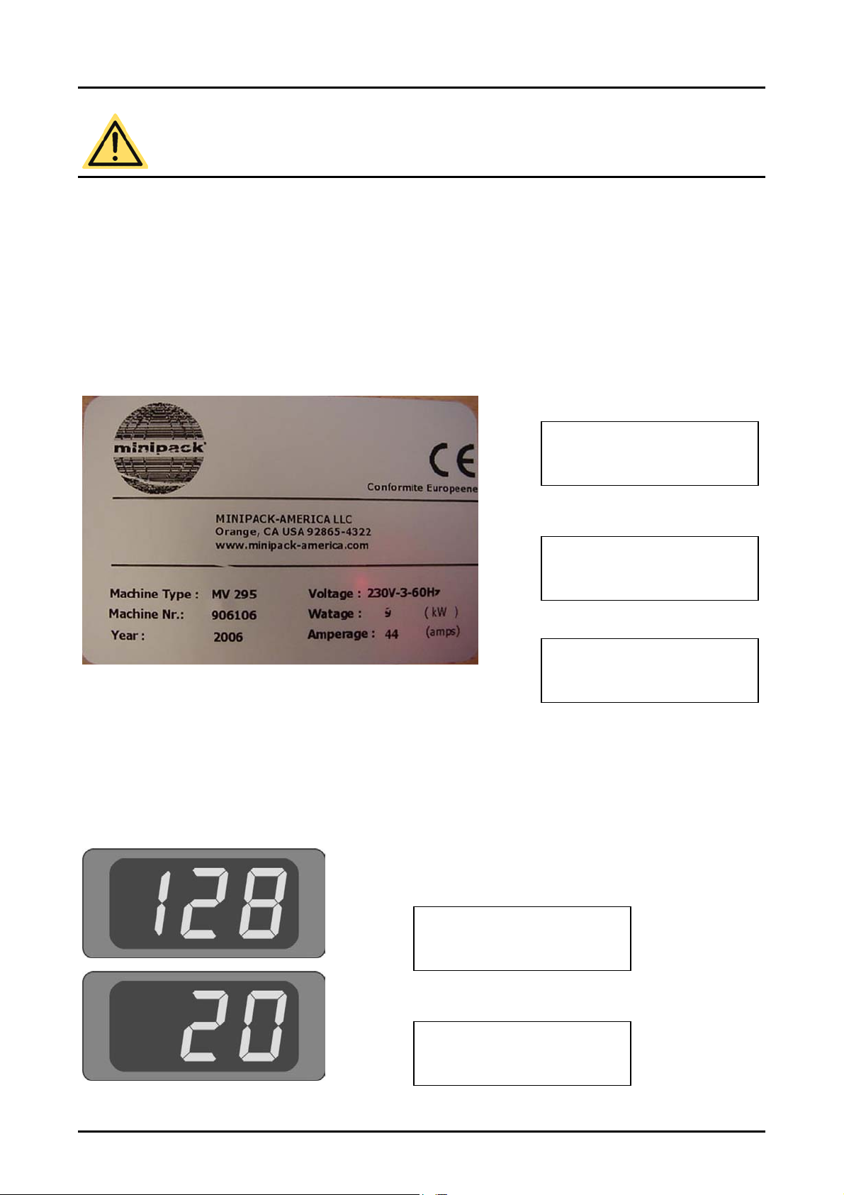
DATA ON MACHINE TAG
Relevant data for answering questions can be found on the machine tag. The machine tag is located at the rear of the
machine. Note down the following data:
CONTROL PANEL DATA
When starting the machine, two codes first appear on the large display in succession before control panel switches to
operation mode. The first code indicates the model of the machine and the second code indicates the control software
version. Write both codes in the space below:
Versie 06.02 DIG.EN 4
MACHINE REGISTRATION TO BE COMPLETED BY THE USER
1. MACHINE TYPE
2. MACHINE NUMBER (MACHINE NO.)
3. VOLTAGE (TENSION)
4. CODE 1
5. CODE 2

MV SWING LID SERIES USER MANUAL
IMPORTANT FOR INSTALLATION!!! READ THIS FIRST!!!
GENERAL
First read this manual carefully before the machine is put into operation.
This manual contains relevant information and instructions for starting up, maintenance and applications.
If problems arise with the machine that could have been avoided by referring to this manual then the guarantee
expires.
Supplier wishes the customer lots of pleasure for an extended period from the purchase of the machine. If there are
any problems or questions then the customer can always approach Minipack or Supplier.
ENVIRONMENT
The machine must be moved or transported in an upright position. The machine may NOT be tilted as this can cause
damage to the pump.
Place the machine on a flat, level floor. This is essential for problem free operation of the machine.
Enough space must be left around the machine for good ventilation. The space must be at least 12 inches.
The ambient temperature in which the machine is operated must be between 41 Farenheit ( 5
(30
for advice.
NEVER place the machine directly next to a heat source or a steaming device (for example a combi-steamer,
dishwasher or stove)
POWER / EARTH
Check that the voltage stated on the machine tag is the same as the mains voltage.
Check the direction which the pump is turning.
Always connect the machine correctly to an earthed socket to avoid danger for fire or electrical shocks (earth
connection is green/yellow).
The power cable must always be free and nothing may be placed on it.
Replace the power cable immediately if damaged.
Always disconnect the power if there are problems with the machine or during maintenance, prior to starting work on
the machine.
If the machine is stationary for long periods then the power should always be disconnected.
0
0
C). When operating the machine in other ambient temperatures the user must contact the Minipack or Supplier
C) and 86 Farenheit
Versie 06.02 DIG.EN 5

MV SWING LID SERIES USER MANUAL
VACUUM PUMP
Check before starting the machine if there is oil in the pump (see page 22). NEVER start the machine without oil in
the pump.
Use the right type of oil for the pump (see page 23).
After moving and/or transporting the machine, always first check the oil level before re-starting operation.
When starting the machine for the first time or after a lengthy idle period, first run the conditioning program before
operating the machine (see page 21).
CONNECTING THE GAS FLUSH SYSTEM (if applicable)
NEVER use flammable gasses or gas mixtures containing too much oxygen. There is a danger of explosion when
using the aforementioned gasses. Accidents and/or damage caused by using abovementioned gasses void all
liability on the part of Supplier as well as the guarantee.
The gas bottles must always be correctly secured. If the gas flush function and/or the machine is not in use then the
main cock of the gas bottle must always be closed.
The pressure of the pressure reducing valve on the gas bottle may NEVER be set to more than 15 Psi.
15 Psi. Is app. equal to 1 atmosphere/ATO.
A higher pressure may damage the machine.
The diameter of the hose nipple connector for the gas is for all machines (MV 250, 275, 285 and 295) 0,51 inch
(13 mm) The connector is at the rear of the machine.
For more information about the use of gas bottles, consult an authorised gas supplier
CONNECTING COMPRESSED AIR FOR EXTERNAL SEALING PRESSURE (if applicable)
The pressure from the compressor may NEVER be set to more than 15 Psi . A higher pressure may damage the
machine.
Only dry compressed air may be used for the external seal pressure.
The diameter of the hose nipple connector the compressor is 0,23 inch (6 mm’ (rear side of the machine)
For more information about the use of compressed air, consult an authorised gas supplier
Versie 06.02 DIG.EN 6

MV SWING LID SERIES USER MANUAL
IMPORTANT FOR OPERATION !!! READ THIS FIRST !!!
GENERAL
Never pack products that can be damaged during or after vacuum packaging. Live oats may never be vacuumed.
Refer to this manual if in doubt as to the operation and/or functioning of the machine. If the manual does not offer a
solution consult the Minipack or Supplier.
The guarantee and/or liability expires if damage is caused by repairs and/or changes made by you. In the case of
malfunctions contact the Minipack or Supplier.
In the case of malfunctions always stop the machine and remove the power cable from the wall socket.
GENERAL MAINTENANCE
It is essential that the machine is serviced regularly to guarantee operation and to keep the machine in optimal and
safe condition. The maintenance schedule is clearly defined on page 21. The guarantee and/or liability automatically
expires due to overdue or sloppy maintenance.
Always remove the power cable from the wall socket for maintenance work; the machine must be completely
disconnected.
If there are doubts about the maintenance activities or if the machine fails to work correctly always contact the
supplier.
Versie 06.02 DIG.EN 7
MV SWING LID SERIES USER MANUAL
VACUUM PUMP
Regularly check the level and quality of the oil in the pump. If there is too little oil or the quality of the oil is bad
(turbid), replace or top up the oil before operating the machine (see page 22). Let the pump conditioning program run
at least one full cycle before replacing the oil (see page 21).
Use the right type of oil for the pump when replacing or filling up (see page 23).
Use the conditioning program at least once a week to enhance correct and long-lasting pump operation (see page
21).
USE OF GAS FLUSH SYSTEM (if applicable)
NEVER use flammable gasses or gas mixtures containing too much oxygen. Use thereof can cause risk of
explosions. Accidents and/or damage caused by using abovementioned gasses voids all liability on the part of
Supplier as well as the guarantee.
The gas bottles must always be correctly secured. If the gassing function and/or the machine is not in use then the
main cock of the gas bottle must always be closed.
The pressure of the pressure reducing valve on the gas bottle may NEVER be set to more than 14,5 Psi. A higher
pressure may damage the machine.
For more information about the use of gas bottles, consult an authorised gas supplier
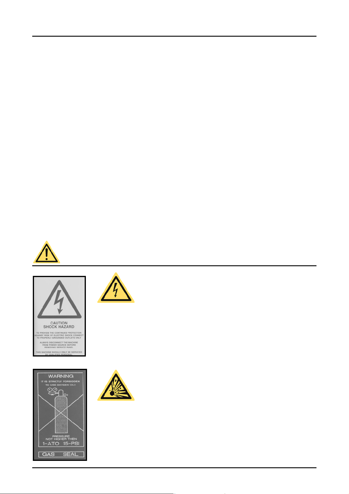
WARNING SIGNS ON THE MACHINE!!!
ONLY use the prescribed power supply voltage.
Insert the plug firmly into the mains wall socket.
Always connect the machine to an earthed wall socket
Always remove the plug during maintenance or when the machine is not in use for extended periods.
NEVER use flammable gasses or gas mixtures containing too much oxygen. Use thereof can cause
risk of explosions
Accidents and/or damage caused by using abovementioned gasses void(s) all liability on the part of
Supplier as well as the guarantee.
Versie 06.02 DIG.EN 8
MV SWING LID SERIES USER MANUAL
A
w
w
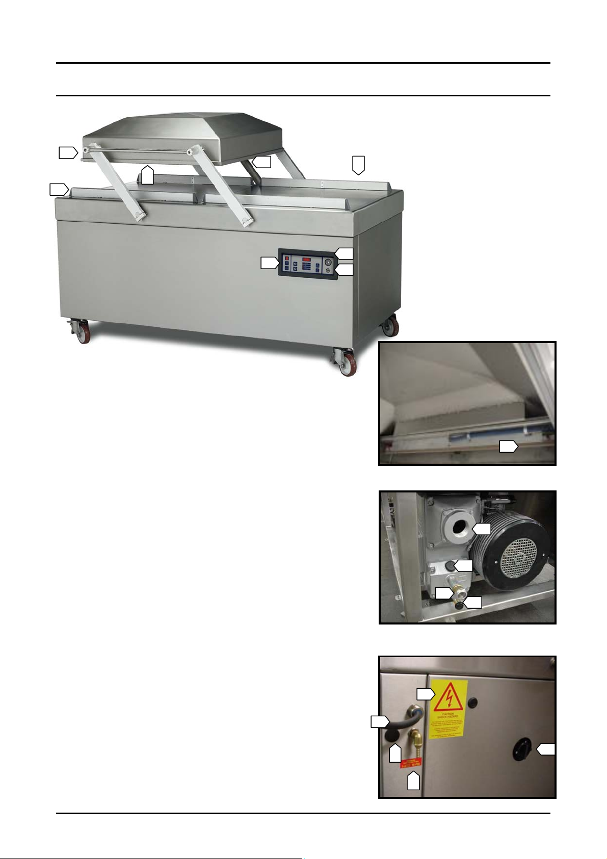
IMPORTANT MACHINE PARTS
4
2
1
5
6
3
8
7
Inside lid
1. Sealing bar(s) in lids mounted by using bolts
2. Silicone holder(s) on holders in on work plate
3. Gas flush nozzles mounted on silicone holders (if applicable)
4. Lid rubber in lid for hermetic seal
5. Vacuum / Ventilation Pipe
6. Control panel
7. ON/OFF switch
8. Vacuum pressure meter
9. Master switch
10. Oil drain plug/elbow
11. Oil filler cap
12. Oil inspection window
13. Exhaust filter opening
14. Power cable
15. Gas bottle connector (if applicable) caution max 1 Bar
16. Seal pressure connector (if applicable) caution max 1 Bar
17. Warning stickers
ppearance of parts and machines can deviate from illustrations
1
Side vie
13
11
12
10
Rear vie
17
14
15
16
Versie 06.02 DIG.EN 9
9
MV SWING LID SERIES USER MANUAL
STARTING AND OPERATING THE MACHINE
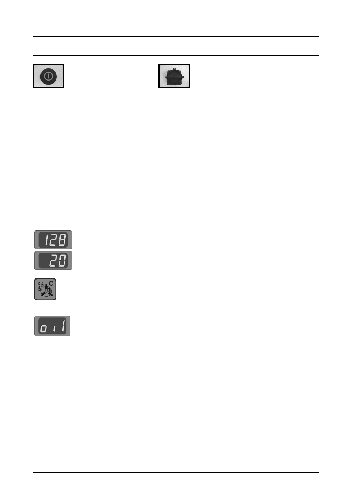
ON/OFF SWITCH MASTER SWITCH
The ON/OFF switch is used to turn the machine on and off before and after operation.
When the machine is turned on (with the ON/OFF switch), the pump runs continuously. The 3 phase pumps need time to
warm up and turning them on and off has a detrimental effect on their lifespan.
A sleeper function is activated on these machines. This means the pump will start running directly when the machine is
switched on, but after finishing the first cycle the pump will stop after 10 minutes. If the next cycle is made within the
mentioned 10 minutes, the pump keeps on running without stopping the pump. Contact your Minipack for more
information on the sleeper function.
STARTING THE MACHINE
When the machine is connected and the master switch is switched to 1 then the machine can be turned on using the
ON/OFF switch. When starting the machine two codes first appear in succession on the large display before control
panel switches to operation mode.
The first code indicates the model of the machine
version. Note both codes on page 4 as they are important for the Minipack or Supplier when making
enquiries and/or if any problems arise.
After switching to operation mode the machine is ready for use. If the machine is new or has been
unused for a longer period of time then it is advisable to run the pump conditioning program (15
minutes) to heat up and clean the pump. For instructions on the conditioning program, see page 21.
After switching to the operation mode the display could read [ OIL ]. This means that the operating
hours counter is turned on and the set number of operating hours has elapsed. The hour counter is
turned off by default but the client or supplier can activate it as a reminder for regular maintenance
activities. This function is default switch OFF.
When [ OIL ] is displayed the machine can be still be used as usual but it is advisable to either turn off
the hour counter or to reset it. More information on how to set or turn off the operating hours counter
can be found on page 16.
. The second code indicates the control software
Versie 06.02 DIG.EN 10
MV SWING LID SERIES USER MANUAL
STANDARD OPERATING STEPS FOR THE MACHINE
1. Turn the machine on with the ON/OFF switch. Heat up the pump with the condition program when machine has
stood idle for some time (instructions page 21).
2. Fill the vacuum bag with product. Select the correct format bag that easily fits around the product but is not too
large for the product. Ensure hygienic conditions during this operation. Packaging materials, product and hands
must be clean and if possible dry.
3. Lay the vacuum bag on the working plate. The open side must be laid over the sealing bar or silicone holder. The
bag may however not extrude from the chamber. If the product is a lot lower than the height of the sealing bar or
silicone holder then insert plates which are supplied standard with the machine can be used. This makes the
operation easier and reduces the cycle time.
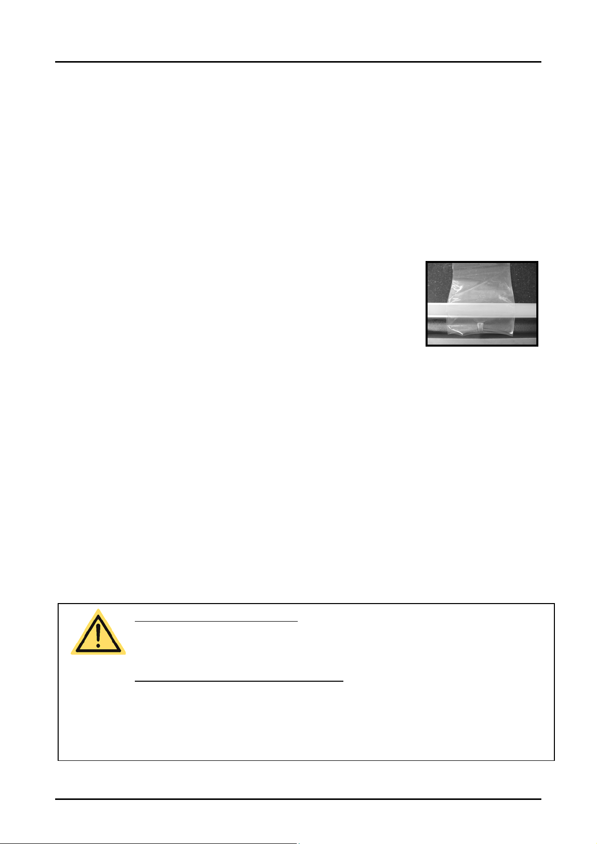
4. The vacuum bag must be laid without folds over the sealing bar or silicone holder.
5. For a gas flush system the opening of the vacuum bag must be pulled over the gas
nozzles (see illustration).
6. Multiple vacuum bags can be placed over the sealing bar/silicone holder if the
sealing bar/silicone holder is longer than the vacuum bag. Vacuum bags may not
however be laid on top of each other on the bar/holder. If there are multiple bars/holders
then all bars/holders can of course be used during the same cycle.
MV SWING LID SERIES
7. Use the [PROG] key to choose the desired program. See page 17 for instructions about programming.
8. Close the lid and the machine automatically runs through the full cycle of all activated functions. The lid opens
automatically when the last function “ventilation” has been completed.
9. If necessary the cycle can be partially or fully interrupted by pressing the [VACUUM STOP] key or the [STOP] key.
The [VACUUM STOP] key interrupts the active function (vacuum, gas flushing, sealing, or soft-air ventilation) and
automatically continues with the next function.
The [STOP] key interrupts the entire cycle and goes immediately to the ventilation function.
10. After cycle completion, the packed product (or products) can be removed from the machine.
11. If the machine is equipped with a cut-off sealing system then the remaining flap on the vacuum bag can be torn off.
SAFETY and PRODUCT PROTECTION
The packing process can be partially or fully interrupted at all times:
Stop active function, press [VACUUM STOP] key
Stop full machine cycle, press [STOP] key
OPTIMAL AND EFFICIENT PACKAGING RESULT
Use the correct size and good quality vacuum bags
Maximum 75% product filling in vacuum bag
Place vacuum bag fold free over sealing bar/silicone holder (use correct number in insert plates in chamber)
Pull vacuum bag far enough over gas nozzles (for gas flush) so that no gas is lost and the bag does not
move during gas flushing
Versie 06.02 DIG.EN 11

MV SWING LID SERIES USER MANUAL
MACHINE CONTROL PANEL
CONTROL PANEL VERSIONS
General
Digital Time Control
Digital Sensor Control
Contact the Minipack or Supplier for information about special operating panels not shown above.
The digital control panels are implemented with 9 pre-select programs that can be individually
set with different function values (to be able to pack different products) Program 0 can not be
set and is used for servicing and testing. A program cycle is the complete program of set
functions that the machine runs through to package a product.
The control panels are designed with a operation mode and a program mode.
The operation mode is used during operational activities for selecting the program number
with the required program cycle. The set values of the function program can also be seen in
the operation mode but not changed.
The program mode is used to change the function values within the programs.
The control panels are implemented standard with an automatic conditioning program for the
regular maintenance of the pump and two STOP keys for complete cycle interruption or for
only active function interruption. There are also a number of built-in service programs. Contact
the Minipack or Supplier for more information about these programs.
The value of all active functions can be set for a certain time period.
The vacuum function, gas flush function (if installed), and soft air function can be set in whole
seconds up to a maximum of 99 seconds.
The seal function can be set with an interval of 0.1 seconds and a maximum of 6.0 seconds.
The value of the vacuum function and the gas flush function (if installed) can be set as a
percentage of the vacuum. This is the percentage of the under pressure in the vacuum
chamber related to the outside pressure 1 atmosphere/ATO (0%).
The maximum vacuum percentage setting of the vacuum function is 99%.
The minimum vacuum percentage setting of the gas flush function is 30%. This means that
the chamber is flushed with gas to 30% under pressure in relation to 1 atmosphere. It is often
expressed as 70% is flushed with gas (99+% - 30% = 70%).
The time for the soft air function can be set on whole seconds (max. 99 seconds).
The time for the seal function can be set on 0.1 seconds (max. 6.0 seconds).
The digital sensor control comes standard with the VACUUM PLUS function. The VACUUM
PLUS function is a time operated additional vacuum function for setting extra time after
reaching the 99% value of the vacuum function (only applicable if 99% is set for the vacuum
function). This function provides additional vacuum time for vacuuming any trapped air out of
the package.
Versie 06.02 DIG.EN 12
 Loading...