

Page 1

LINK:
CONTENT & A-Z
OWNER'S MANUAL.
MINI HARDTOP 2 DOOR / 4 DOOR.
Online Edition for Part no. 01402723718 - VI/18
Page 2

Online Edition for Part no. 01402723718 - VI/18
Page 3

WELCOME TO MINI.
OWNER'S MANUAL.
MINI HARDTOP 2 DOOR / 4 DOOR.
Thank you for choosing a MINI.
The more familiar you are with your vehicle, the better control you will have
on the road. We therefore strongly suggest:
Read this Owner's Manual before starting off in your new MINI. Also use the
Integrated Owner's Manual in your vehicle. It contains important information
on vehicle operation that will help you make full use of the technical features
available in your MINI. The manual also contains information designed to
enhance operating reliability and road safety, and to contribute to
maintaining the value of your MINI.
Any updates made after the editorial deadline can be found in the appendix of
the printed Owner's Manual for the vehicle.
Get started now. We wish you driving fun and inspiration with your MINI.
Online Edition for Part no. 01402723718 - VI/18
3
Page 4

TABLE OF CONTENTS
NOTES
Information.............................................................................................................................. 8
QUICK REFERENCE
Your MINI at a glance........................................................................................................20
AT A GLANCE
Cockpit.................................................................................................................................... 38
Central Information Display (CID)..................................................................................42
Voice activation system.................................................................................................... 51
General settings................................................................................................................... 54
Owner's Manual media.......................................................................................................66
CONTROLS
Opening and closing........................................................................................................... 70
Seats, mirrors, and steering wheel.................................................................................89
Transporting children safely............................................................................................99
Driving..................................................................................................................................104
Displays................................................................................................................................128
Lights.................................................................................................................................... 147
Safety.....................................................................................................................................153
Driving stability control systems.................................................................................174
Driving comfort................................................................................................................. 179
Climate control...................................................................................................................199
Interior equipment............................................................................................................207
Storage compartments.....................................................................................................214
Cargo area............................................................................................................................217
4
Online Edition for Part no. 01402723718 - VI/18
Page 5

Navigation, Entertainment and Communication can be called up via
the Integrated Owner's Manual in the vehicle.
DRIVING TIPS
Things to remember when driving.............................................................................. 226
Saving fuel...........................................................................................................................231
MOBILITY
Refueling..............................................................................................................................240
Fuel........................................................................................................................................242
Wheels and tires................................................................................................................244
Engine compartment........................................................................................................267
Engine oil.............................................................................................................................270
Coolant..................................................................................................................................274
Maintenance....................................................................................................................... 276
Replacing components.................................................................................................... 278
Breakdown assistance..................................................................................................... 289
Care........................................................................................................................................297
REFERENCE
Technical data.................................................................................................................... 304
Appendix..............................................................................................................................308
Everything from A to Z....................................................................................................310
© 2018 Bayerische Motoren Werke
Aktiengesellschaft
Munich, Germany
Reprinting, including excerpts, only with the written consent of BMW AG, Munich.
US English ID5 VI/18, 07 18 490
Printed on environmentally friendly paper, bleached without chlorine, suitable for recycling.
Online Edition for Part no. 01402723718 - VI/18
5
Page 6

6
Online Edition for Part no. 01402723718 - VI/18
Page 7

NOTES
Information ................................................................................................... 8
Online Edition for Part no. 01402723718 - VI/18
7
Page 8

NOTES Information
Information
Using this Owner's Manual
Orientation
The fastest way to find information on a
particular topic is by using the index.
An initial overview of the vehicle is provided in the first chapter.
Updates made after the editorial
deadline
Due to updates after the editorial deadline,
differences may exist between the printed
Owner's Manual and the Integrated Owner's
Manual in the vehicle.
Notes on updates can be found in the appendix of the printed Owner's Manual for
the vehicle.
Owner's Manual for Navigation,
Entertainment, Communication
The Owner's Manual for Navigation, Entertainment, and Communication can be obtained as printed book from the service center.
The topics are also discussed in the
Integrated Owner's Manual in the vehicle.
are available on the Internet: www.miniusa.com.
Integrated Owner's Manual in the
vehicle
The Integrated Owner's Manual specifically
describes features and functions found in
the vehicle. The Integrated Owner's Manual
can be displayed on the Control Display. Additional information, refer to page 66.
MINI Motorer’s Guide app
The app specifically describes features and
functions found in the vehicle. The app can
be displayed on smartphones and tablets.
MINI Driver’s Guide Web
Driver’s Guide Web shows the most suitable information for the selected vehicle. If
possible, only equipment and functions that
are actually installed in the vehicle will be
explained. Driver’s Guide Web can be displayed in any current browser.
Symbols and displays
Symbols in the Owner's Manual
Additional sources of information
Dealer’s service center
A dealer’s service center will be glad to answer questions at any time.
Internet
The Owner's Manual and general Information about MINI, for example on technology,
8
Online Edition for Part no. 01402723718 - VI/18
Symbol Meaning
Precautions that must be
followed in order to avoid the
possibility of injury to yourself
and to others as well as serious
damage to the vehicle.
Measures that can be taken to
help protect the environment.
Page 9

Information NOTES
Symbol Meaning
"..." Control Display texts used to
select individual functions.
›...‹ Verbal instructions to use with
the voice activation system..
››...‹‹ Responses generated by the
voice activation system.
Action steps
Action steps to be carried out are presented
as numbered list. The steps must be carried
out in the defined order.
1. First action step.
2. Second action step.
Enumerations
Enumerations without mandatory order or
alternative possibilities are presented as list
with bullet points.
– First possibility.
– Second possibility.
This also applies to safety-related functions
and systems.
When using these functions and systems,
the applicable laws and regulations must be
observed.
For any options and equipment not described in this Owner's Manual, refer to the
Supplementary Owner's Manuals.
Your dealer’s service center is happy to answer any questions that you may have
about the features and options applicable to
your vehicle.
Status of the Owner's Manual
Basic information
The manufacturer of your vehicle pursues a
policy of constant development that is conceived to ensure that our vehicles continue
to embody the highest quality and safety
standards. In rare cases, therefore, the features described in this Owner's Manual may
differ from those in your vehicle.
Symbols on vehicle components
This symbol on a vehicle component
indicates that further information on the
component is available in the Owner's
Manual.
Vehicle features and options
This Owner's Manual describes all models
and all standard, country-specific and optional equipment that is offered in the
model series. Therefore, this Owner's
Manual also describes and illustrates features and functions that are not available in
a vehicle, for example because of the selected optional features or the country-specific version.
Online Edition for Part no. 01402723718 - VI/18
Updates made after the editorial
deadline
Due to updates after the editorial deadline,
differences may exist between the printed
Owner's Manual and the Integrated Owner's
Manual in the vehicle.
Notes on updates can be found in the appendix of the printed Owner's Manual for
the vehicle.
For Your Own Safety
Manufacturer
The manufacturer of this MINI is Bayerische Motoren Werke Aktionengesellschaft,
BMW AG.
9
Page 10

NOTES Information
Intended use
Follow the following when using the vehicle:
– Owner's Manual.
– Information on the vehicle. Do not re-
move stickers.
– Technical vehicle data.
– The traffic, speed, and safety laws where
the vehicle is driven.
– Vehicle documents and statutory docu-
ments.
Warranty
Your vehicle is technically configured for
the operating conditions and registration
requirements applying in the country of
first delivery, also known as homologation.
If your vehicle is to be operated in a different country it might be necessary to adapt
your vehicle to potentially differing operating conditions and registration requirements. If your vehicle does not comply with
the homologation requirements in a certain
country you may not be able to lodge warranty claims for your vehicle there. Further
information on warranty is available from a
dealer’s service center.
Maintenance and repairs
WARNING
Improperly performed work on the vehicle
paint can lead to a failure or malfunction
of the radar sensors and thereby result in a
safety risk. There is a risk of accidents or
risk of damage to property. Have paintwork or paintwork repairs on bumpers of
vehicles with radar sensors performed by a
dealer’s service center or another qualified
service center or repair shop only.
Advanced technology, e. g. the use of modern materials and high-performance elec-
tronics, requires suitable maintenance and
repair work.
The manufacturer of your vehicle recommends that you entrust corresponding procedures to a MINI dealer’s service center. If
you choose to use another service facility,
the manufacturer of your vehicle recommends use of a facility that performs work,
for instance maintenance and repair, according to MINI specifications with properly trained personnel, referred to in this
Owner's Manual as "another qualified service center or repair shop".
If work is performed improperly, for instance maintenance and repair, there is a
risk of subsequent damage and related
safety risks.
Parts and accessories
The manufacturer of your vehicle recommends the use of parts and accessory products approved by the manufacturer of the
MINI.
Approved parts and accessories, and advice
on their use and installation are available
from a MINI dealer's service center.
MINI parts and accessories were tested by
the manufacturer of the MINI for their
safety and suitability in MINI vehicles.
The manufacturer of your vehicle warrants
genuine MINI parts and accessories.
The manufacturer of your vehicle does not
evaluate whether each individual product
from another manufacturer can be used
with MINI vehicles without presenting a
safety hazard, even if a country-specific official approval was issued. The manufacturer of your vehicle does not evaluate
whether these products are suitable for
MINI vehicles under all usage conditions.
California Proposition 65 Warning
California law requires vehicle manufacturers provide the following warning:
10
Online Edition for Part no. 01402723718 - VI/18
Page 11

WARNING
Engine exhaust and a wide variety of Automobile components and parts, including
components found in the interior furnishings in a vehicle, contain or emit chemicals known to the State of California to
cause cancer and birth defects and reproductive harm. In addition, certain fluids
contained in vehicles and certain products
of component wear contain or emit chemicals known to the State of California to
cause cancer and birth defects or other reproductive harm. Battery posts, terminals
and related accessories contain lead and
lead compounds. Batteries also contain
other chemicals known to the State of California to cause cancer. Wash your hands
after handling. Used engine oil contains
chemicals that have caused cancer in laboratory animals. Always protect your skin
by washing thoroughly with soap and water. For more information go to
www.P65Warnings.ca.gov/passenger-vehicle.
WARNING
Operating, servicing and maintaining a
passenger vehicle or off-highway motor
vehicle can expose you to chemicals including engine exhaust, carbon monoxide,
phthalates, and lead, which are known to
the State of California to cause cancer and
birth defects or other reproductive harm.
To minimize exposure, avoid breathing exhaust, do not idle the engine except as
necessary, service your vehicle in a wellventilated area and wear gloves or wash
your hands frequently when servicing
your vehicle. For more information go to
www.P65Warnings.ca.gov/passenger-vehicle.
Information NOTES
Service and warranty
We recommend that you read this publication thoroughly. Your vehicle is covered by
the following warranties:
– New Vehicle Limited Warranty.
– Rust Perforation Limited Warranty.
– Federal Emissions System Defect War-
ranty.
– Federal Emissions Performance War-
ranty.
– California Emission Control System Lim-
ited Warranty.
Detailed information about these warranties
is listed in the Service and Warranty Information Booklet for US models or in the Warranty and Service Guide Booklet for Canadian models.
Your vehicle has been specifically adapted
and designed to meet the particular operating conditions and homologation requirements in your country and continental region in order to deliver the full driving
pleasure while the vehicle is operated under
those conditions. If you wish to operate
your vehicle in another country or region,
you may be required to adapt your vehicle
to meet different prevailing operating conditions and homologation requirements.
You should also be aware of any applicable
warranty limitations or exclusions for such
country or region. In such case, please contact Customer Relations for further information.
Maintenance
Maintain the vehicle regularly to sustain
the road safety, operational reliability and
the New Vehicle Limited Warranty.
Specifications for required maintenance
measures:
– MINI Maintenance system.
Online Edition for Part no. 01402723718 - VI/18
11
Page 12

NOTES Information
– Service and Warranty Information Book-
let for US models.
– Warranty and Service Guide Booklet for
Canadian models.
If the vehicle is not maintained according to
these specifications, this could result in serious damage to the vehicle. Such damage is
not covered by the MINI New Vehicle Limited Warranty.
Data memory
General information
Electronic control devices are installed in
the vehicle. Electronic control units process
data they receive from vehicle sensors, selfgenerate or exchange with each other. Some
control units are necessary for the vehicle
to function safely or provide assistance during driving, for instance driver assistance
systems. Furthermore, control devices facilitate comfort or infotainment functions.
Information about stored or exchanged data
can be requested from the manufacturer of
the vehicle, in a separate booklet, for example.
Personal reference
Each vehicle is marked with a unique vehicle identification number. Depending on the
country, the vehicle owner can be identified
with the vehicle identification number, license plate and corresponding authorities.
In addition, there are other options to track
data collected in the vehicle to the driver or
vehicle owner, e.g. via utilized services.
Operating data in the vehicle
Control units process data to operate the vehicle.
For example, this includes:
– Status messages for the vehicle and its
individual components, e.g., wheel rotational speed, wheel speed, deceleration,
transverse acceleration, engaged safety
belt indicator.
– Ambient conditions, e.g., temperature,
rain sensor signals.
The processed data is only processed in the
vehicle itself and generally volatile. The
data is not stored beyond the operating period.
Electronic components, e.g. control units
and ignition keys, contain components for
storing technical information. Information
about the vehicle condition, component usage, maintenance requirements or faults
can be stored temporarily or permanently.
This information generally records the state
of a component, a module, a system, or the
environment, for instance:
– Operating states of system components,
e.g., fill levels, tire inflation pressure,
battery status.
– Malfunctions and faults in important
system components, for instance lights
and brakes.
– Responses by the vehicle to special sit-
uations such as airbag deployment or
engagement of the driving stability control systems.
– Information on vehicle-damaging
events.
The data is required to perform the control
device functions. Furthermore, it also
serves to recognize and correct malfunctions, and helps the vehicle manufacturer to
optimize vehicle functions.
The majority of this data is transient and is
only processed within the vehicle itself.
Only a small share of the data is stored
event-related in event or fault memories.
When servicing, for instance during repairs,
service processes, warranty cases, and qual-
12
Online Edition for Part no. 01402723718 - VI/18
Page 13

Information NOTES
ity assurance measures, this technical information can be read out from the vehicle together with the vehicle identification
number.
A dealer’s service center or another qualified service center or repair shop can read
out the information. The socket for OBD Onboard Diagnosis required by law in the vehicle is used to read out the data.
The data is collected, processed, and used
by the relevant organizations in the service
network. The data documents technical conditions of the vehicle, helps with the identification of the fault, compliance with warranty obligations and quality improvement.
Furthermore, the manufacturer has product
monitoring duties to meet in line with product liability law. To fulfill these duties, the
vehicle manufacturer needs technical data
from the vehicle. The data from the vehicle
can also be used to check customer claims
for warranty and guaranty.
Fault and event memories in the vehicle can
be reset when a dealer’s service center or
another qualified service center or repair
shop performs repair or servicing work.
Data entry and data transfer into
the vehicle
General information
Depending on the vehicle equipment, comfort and individual settings can be stored in
the vehicle and modified or reset at any
time.
For example, this includes:
– Settings for the seat and steering wheel
positions.
– Suspension and climate control settings.
If necessary, data can be transferred to the
entertainment and communication system
of the vehicle, e.g. via smartphone.
This includes the following depending on
the respective equipment:
– Multimedia data such as music, films or
photos for playback in an integrated
multimedia system.
– Address book data for use in conjunc-
tion with an integrated hands-free sys-
tem or an integrated navigation system.
– Entered navigation destinations.
– Data on the use of Internet services.
This data can be stored locally in the vehicle
or is found on a device that has been connected to the vehicle, e.g., a smartphone,
USB stick or MP3 player. If this data is
stored in the vehicle, it can be deleted at
any time.
This data is only transmitted to third parties
upon personal request as part of the use of
online services. This depends on the selected settings for the use of the services.
Incorporation of mobile end devices
Depending on the vehicle equipment, mobile devices connected to the vehicle, for instance smartphones, can be controlled via
the vehicle control elements.
The sound and picture from the mobile device can be played back and displayed
through the multimedia system. Certain information is transferred to the mobile device at the same time. Depending on the
type of incorporation, this includes, for instance position data and other general vehicle information. This optimizes the way in
which selected apps, for instance navigation
or music playback, work.
There is no further interaction between the
mobile device and the vehicle, for instance
active access to vehicle data.
How the data will be processed further is
determined by the provider of the particular
app being used. The extent of the possible
Online Edition for Part no. 01402723718 - VI/18
13
Page 14

NOTES Information
settings depends on the respective app and
the operating system of the mobile device.
Services
General information
If the vehicle has a wireless network connection, this enables data to be exchanged
between the vehicle and other systems. The
wireless network connection is realized via
an in-vehicle transmitter and receiver unit
or via personal mobile devices brought into
the vehicle, for instance smartphones. This
wireless network connection enables 'online
functions' to be used. These include online
services and apps supplied by the vehicle
manufacturer or by other providers.
Services from the vehicle
manufacturer
Where online services from the vehicle
manufacturer are concerned, the corresponding functions are described in the appropriate place, for instance the Owner's
Manual or manufacturer's website. The relevant legal information pertaining to data
protection is provided there too. Personal
data may be used to perform online services. Data is exchanged over a secure connection, for instance with the IT systems of
the vehicle manufacturer intended for this
purpose.
Any collection, processing, and use of personal data above and beyond that needed to
provide the services must always be based
on a legal permission, contractual arrangement or consent. It is also possible to activate or deactivate the data connection as a
whole. That is, with the exception of functions and services required by law such as
Assist systems.
Services from other providers
When using online services from other providers, these services are the responsibility
of the relevant provider and subject to their
data privacy conditions and terms of use.
The vehicle manufacturer has no influence
on the content exchanged during this process. Information on the way in which personal data is collected and used in relation
to services from third parties, the scope of
such data, and its purpose, can be obtained
from the relevant service provider.
Event Data Recorder EDR
This vehicle is equipped with an event data
recorder EDR. The main purpose of an EDR
is to record, in certain crash or near crashlike situations, such as an air bag deployment or hitting a road obstacle, data that
will assist in understanding how a vehicle’s
systems performed. The EDR is designed to
record data related to vehicle dynamics and
safety systems for a short period of time,
typically 30 seconds or less.
The EDR in this vehicle is designed to record such data as:
– How various systems in your vehicle
were operating.
– Whether or not the driver and passen-
ger safety belts were fastened.
– How far, if at all, the driver was depress-
ing the accelerator and/or brake pedal.
– How fast the vehicle was traveling.
This data can help provide a better understanding of the circumstances in which
crashes and injuries occur.
EDR data is recorded by your vehicle only if
a nontrivial crash situation occurs; no data
is recorded by the EDR under normal driving conditions and no personal data, for instance name, gender, age, and crash location, are recorded.
However, other parties, such as law enforcement, could combine the EDR data with the
14
Online Edition for Part no. 01402723718 - VI/18
Page 15
Information NOTES
type of personally identifying data routinely
acquired during a crash investigation.
To read data recorded by an EDR, special
equipment is required, and access to the vehicle or the EDR is needed. In addition to
the vehicle manufacturer, other parties,
such as law enforcement, that have the special equipment, can read the information if
they have access to the vehicle or the EDR.
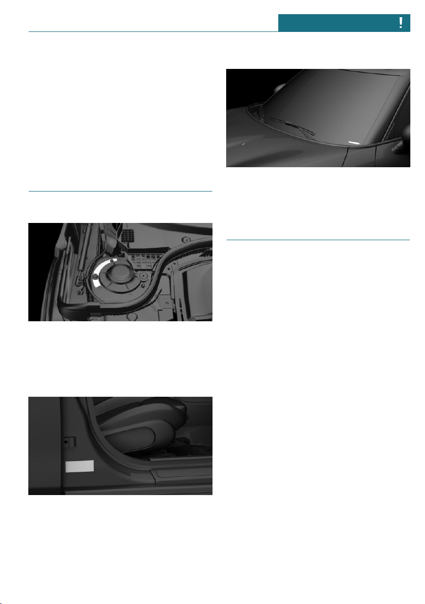
Vehicle identification number
Engine compartment
The vehicle identification number can be
found in the engine compartment, on the
right-hand side of the vehicle.
Type label
The vehicle identification number can be
found on the type label, on the right-hand
side of the vehicle.
Windshield
The vehicle identification number can also
be found behind the windshield.
Reporting safety defects
For US customers
The following only applies to vehicles
owned and operated in the US.
If you believe that your vehicle has a defect
which could cause a crash or could cause injury or death, you should immediately inform the National Highway Traffic Safety
Administration NHTSA, in addition to notifying MINI of North America, LLC, P.O. Box
1227, Westwood, New Jersey 07675-1227,
Telephone 1-800-831-1117.
If NHTSA receives similar complaints, it
may open an investigation, and if it finds
that a safety defect exists in a group of vehicles, it may order a recall and remedy
campaign.
However, NHTSA cannot become involved
in individual problems between you, your
dealer, or MINI of North America, LLC.
To contact NHTSA, you may call the Vehicle
Safety Hotline toll-free at 1-888-327-4236
(TTY: 1-800-424-9153); go to http://
www.safercar.gov; or write to: Administrator, NHTSA, 400 Seventh Street, SW.,
Washington, DC 20590. You can also obtain
Online Edition for Part no. 01402723718 - VI/18
15
Page 16

NOTES Information
other information about motor vehicle
safety from http://www.safercar.gov
For Canadian customers
Canadian customers who wish to report a
safety-related defect to Transport Canada,
Defect Investigations and Recalls, may call
the toll-free hotline 1-800-333-0510. You
can also obtain other information about motor vehicle safety from http://www.tc.gc.ca/
roadsafety.
16
Online Edition for Part no. 01402723718 - VI/18
Page 17

Information NOTES
Online Edition for Part no. 01402723718 - VI/18
17
Page 18

18
Online Edition for Part no. 01402723718 - VI/18
Page 19

QUICK REFERENCE
Your MINI at a glance ............................................................................ 20
Online Edition for Part no. 01402723718 - VI/18
19
Page 20
QUICK REFERENCE Your MINI at a glance
Your MINI at a glance
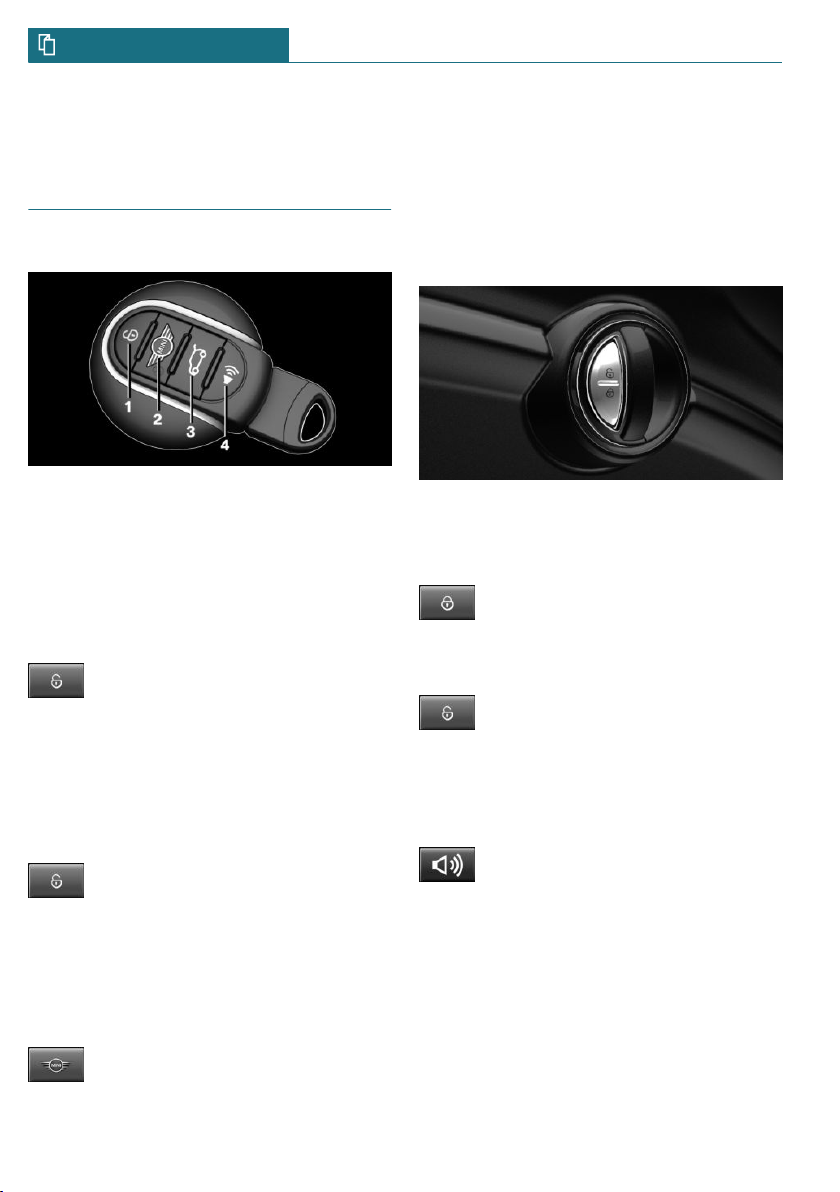
Opening and closing
Buttons on the remote control
1 Unlocking
2 Locking
3 Unlocking the tailgate
4 Panic mode
Unlocking the vehicle
Press button on the remote control.
Depending on the settings, either only the
driver's door or all vehicle access points are
unlocked.
If only the driver's door is unlocked, press
the button of the remote control again to
unlock the other vehicle access points.
Press and hold this button on the
remote control after unlocking.
The windows and the glass sunroof are
opened, as long as the button on the remote
control is pressed.
Locking the vehicle
Press button on the remote control.
Buttons for the central locking
system
Overview
Buttons for the central locking system.
Locking
Pressing the button locks the vehicle if the front doors are closed.
Unlocking
Pressing the button unlocks the vehicle.
Panic mode
You can trigger the alarm system if you find
yourself in a dangerous situation.
Press button on the remote control
and hold for at least 3 seconds.
To switch off the alarm: press any button.
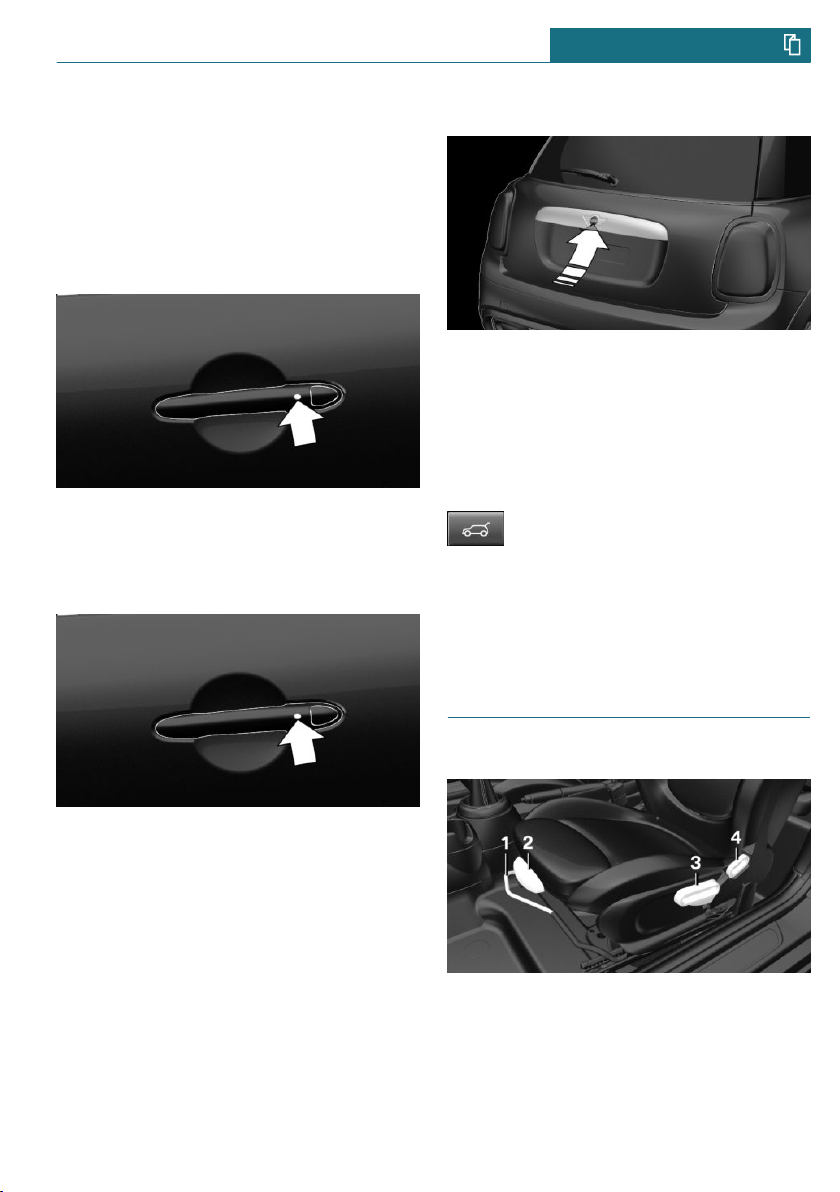
Comfort Access
Concept
The vehicle can be accessed without activating the remote control.
All vehicle access points are locked.
20
Online Edition for Part no. 01402723718 - VI/18
Page 21
Your MINI at a glance QUICK REFERENCE
All you need to do is to have the remote
control with you, such as in your pants
pocket.
The vehicle automatically detects the remote control when it is in close proximity
or in the car's interior.
Unlocking the vehicle
On the driver's or front passenger's door
handle, press the button.
Locking the vehicle
Unlocking the tailgate
Unlock the vehicle and press the button on
the tailgate.
– Unlock the vehicle and press the button
on the tailgate.
– If carrying the remote control, press the
button on the tailgate.
Press and hold button on the remote
control for approx. 1 second.
Depending on the setting, the doors may be
unlocked.
Seats, mirrors, and steering wheel
On the driver's or front passenger's door
handle, press the button.
Online Edition for Part no. 01402723718 - VI/18
Manually adjustable seats
1 Forward/backward
2 Thigh support
3 Height
4 Backrest tilt
21
Page 22
QUICK REFERENCE Your MINI at a glance
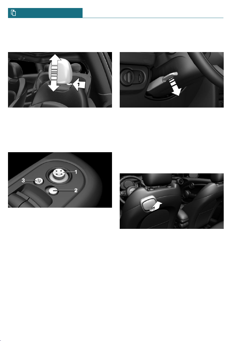
Adjusting the head restraint
Height
– To raise: push the head restraint up.
– To lower: press the button, arrow 1, and
push the head restraint down.
Adjusting the exterior mirrors
Adjusting the steering wheel
In four directions
1. Fold the lever down.
2. Move the steering wheel to the prefer-
red height and angle to suit your seating
position.
3. Fold the lever back up.
Entering the rear
1. Pull lever up to the stop.
1 Settings
2 Selecting a mirror, Automatic Curb Mon-
itor
3 Folding in and out
22
Online Edition for Part no. 01402723718 - VI/18
2. Fold backrest forward.
3. Push the seat forward.
Original position
1. Push the seat back into the original po-
sition.
2. Fold back the backrest to lock the seat.
Page 23
Your MINI at a glance QUICK REFERENCE
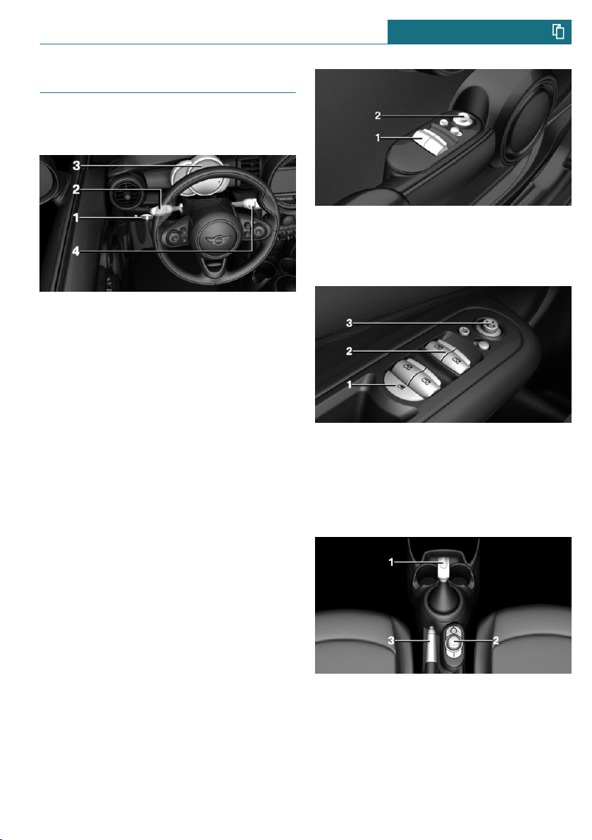
Displays and control elements
In the vicinity of the steering
wheel
1 Low beams, fog lights
2 High beams, headlight flasher, turn sig-
nal
3 Instrument cluster
4 Washer/wiper system
Indicator/warning lights
Instrument cluster
The indicator/warning lights can light up in
a variety of combinations and colors.
Several of the lights are checked for proper
functioning and light up temporarily when
the engine is started or the ignition is
switched on.
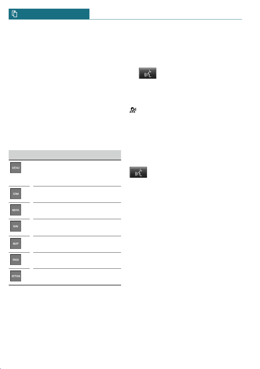
1 Power windows
2 Exterior mirrors
For 5-door models:
1 Safety switch
2 Power windows
3 Exterior mirrors
All around the selector lever
Driver's door
For 3-door models:
1 Selector lever
2 Controller with buttons
3 Parking brake
Online Edition for Part no. 01402723718 - VI/18
23
Page 24
QUICK REFERENCE Your MINI at a glance
Central Information Display (CID)
Concept
The Central Information Display (CID) combines the functions of a multitude of
switches. These functions can be operated
via the Controller or touchscreen.
Controller
General information
The buttons can be used to open the menus
directly. The Controller can be used to select menu items and enter the settings.
Buttons on the Controller
Button Function
Press once: call up main menu.
Press twice: open recently used
menus.
Open the Communication menu.
Open the Media/Radio menu.
Open destination input menu for
navigation.
Open navigation map.
Open the previous display.
Open the Options menu.
Voice activation
Using the voice activation system
Activating the voice activation system
1. Press the button on the steering
wheel.
2. Wait for the signal.
3. Say the command.
This symbol in the instrument cluster
indicates that the voice activation system is
active.
If no other commands are available, operate
the function via the Central Information
Display (CID).
Terminating the voice activation system
Press the button on the steering
wheel or ›Cancel‹.
Help on the voice activation system
– To have information on the operating
principle of the voice activation system
read out loud: ›General information on
voice control‹.
– To have help for the current menu read
out loud: ›Help‹.
Information on Emergency Requests
Do not use the voice activation system to
initiate an Emergency Request. In stressful
situations, the voice and vocal pitch can
change. This can unnecessarily delay the establishment of a phone connection.
Instead, use the SOS button close to the interior mirror.
24
Online Edition for Part no. 01402723718 - VI/18
Page 25
Your MINI at a glance QUICK REFERENCE
Driving
Starting and stopping the engine
Ignition on/off
– On: press the Start/Stop
button.
Most of the indicator/
warning lights light up for
a varied length of time.
– Off: press the Start/Stop button again.
All indicator lights go out.
– Radio-ready state: when the ignition is
switched off, press the ON/OFF button
on the radio or when the engine is running, press the Start/Stop button.
Some electronic systems/power consumers remain ready for operation.
Starting/stopping the engine
Steptronic transmission: starting
1. Depress the brake pedal.
2. Engage selector lever position P or N.
3. Press the Start/Stop button.
Manual transmission: switching off
1. With the vehicle at a standstill, press
the Start/Stop button.
2. Shift into first gear or reverse.
3. Set the parking brake.
Auto Start/Stop function
Steptronic transmission: switches the engine off automatically while stationary to
save fuel. The engine starts automatically
when the brake pedal is released.
Manual transmission: switches the engine
off automatically while stationary to save
fuel. As soon as the clutch pedal is depressed, the engine starts automatically.
Parking brake
Applying
The lever automatically engages after being
pulled up.
Releasing
Manual transmission: starting
1. Depress the brake pedal.
2. Press on the clutch pedal and shift to
neutral.
3. Press the Start/Stop button.
Steptronic transmission: switching off
1. When the vehicle is stationary, apply
the parking brake.
2. Engage selector lever position P.
3. Press the Start/Stop button.
Online Edition for Part no. 01402723718 - VI/18
Raise lever slightly, press the button and
guide the lever down.
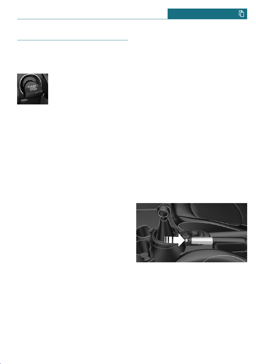
Manual transmission
Shifting
When shifting into 5th or 6th gear, push
the gearshift lever to the right in order to
prevent inadvertent shifting into the 3rd or
4th gear.
25
Page 26
QUICK REFERENCE Your MINI at a glance
Reverse gear
Select only when the vehicle is stationary.
To overcome the resistance push the gear-
shift lever dynamically to the left and engage reverse gear with a forward shifting
movement.
Steptronic transmission
Selector lever positions
Parking position P.
Reverse R.
Neutral N.
Drive mode D.
Engage selector lever position P or R only
when the vehicle is stationary.
To prevent the vehicle from creeping after
you select a drive mode or reverse, maintain
pressure on the brake pedal until you are
ready to start.
Selector lever lock
A lock prevents an inadvertent change from
selector lever position P to another selector
lever position and, depending on the transmission version, inadvertent switching to
selector lever position P or R.
To release the lock: with the brake pedal depressed, press the button on the front or
side of the selector lever.
Steptronic transmission, Sport and
manual mode
Sport program:
Press the selector lever to the left out of se-
lector lever position D.
Manual mode:
– To shift down: press the selector lever
forward.
– To shift up: pull the selector lever rear-
wards.
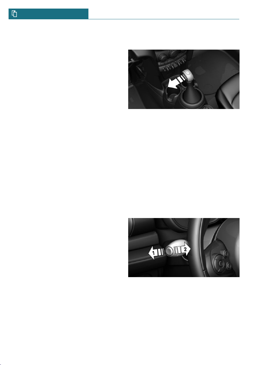
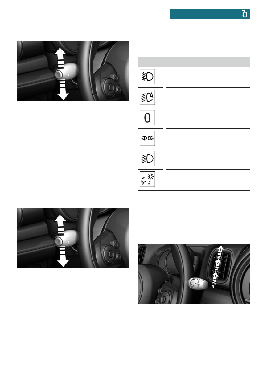
High beams, headlight flasher, turn
signal, roadside parking light
High beams, headlight flasher
26
Push the lever forward or pull it backward.
– High beams on, arrow 1.
The high beams light up when the low
beams are switched on.
– High beams off/headlight flasher, ar-
row 2.
Online Edition for Part no. 01402723718 - VI/18
Page 27
Your MINI at a glance QUICK REFERENCE
Turn signal
– On: press the lever past the resistance
point.
– Off: lightly tap the lever to the resist-
ance point.
– Off: press the lever past the resistance
point in the opposite direction.
– Triple turn signal activation: lightly tap
the lever up or down.
– Brief signaling: press the lever to the re-
sistance point and hold it there for as
long as you want the turn signal to flash.
Canada: roadside parking light
Lights and lighting
Light functions
Symbol Function
Front fog lights.
Automatic headlight control.
Lights off.
Daytime running lights.
Parking lights.
Low beams.
Instrument lighting.
Washer/wiper system
Illuminate the vehicle on one side.
– On: with the ignition switched off, press
the lever either up or down past the resistance point for approx. 2 seconds.
– Off: briefly press the lever to the resist-
ance point in the opposite direction.
Online Edition for Part no. 01402723718 - VI/18
Switching the wipers on/off and brief
wipe
Switching on
Press the lever up until the desired position
is reached.
– Resting position of the wipers: posi-
tion 0.
27
Page 28
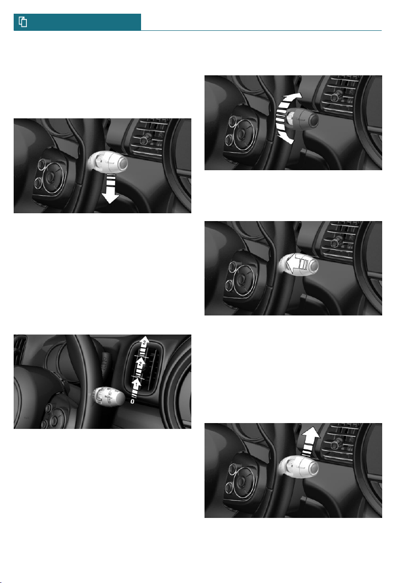
QUICK REFERENCE Your MINI at a glance
– Rain sensor: position 1.
– Normal wiper speed: position 2.
– Fast wiper speed: position 3.
Brief wipe and switching off
Press the lever down.
– Switching off: press the lever down until
it reaches its standard position.
– Brief wipe: press the lever down from
the standard position.
Rain sensor
Activating/deactivating
Set interval or sensitivity of the rain
sensor
Turn the thumbwheel on the wiper lever.
Cleaning the windshield
Pull the lever.
To activate: press the lever up once from its
standard position, arrow 1.
To deactivate: press the lever back into the
standard position.
28
Online Edition for Part no. 01402723718 - VI/18
Canada: wiper system
Switching the wipers on/off and brief
wipe
Switching on
Tap up the lever or press it past the resistance point.
Page 29
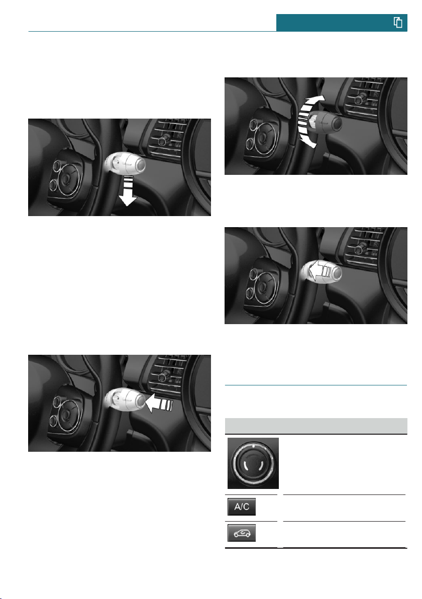
Your MINI at a glance QUICK REFERENCE
– Normal wiper speed: tap up once.
– Fast wiper speed: tap up twice or tap
once beyond the resistance point.
Brief wipe and switching off
Press the lever down.
– To switch off fast wipe: press down
twice.
– To switch off normal wipe: press down
once.
– Brief wipe: press down once.
Rain sensor
Activating/deactivating
Set interval or sensitivity of the rain
sensor
Turn the thumbwheel on the wiper lever.
Cleaning the windshield
Pull the lever.
Press the button on the wiper lever.
Online Edition for Part no. 01402723718 - VI/18
Climate control
Air conditioner
Button Function
Temperature.
Air conditioning.
Recirculated-air mode.
29
Page 30
QUICK REFERENCE Your MINI at a glance
Button Function
Control the air flow, manual.
Control the manual air distribution.
Windshield defroster.
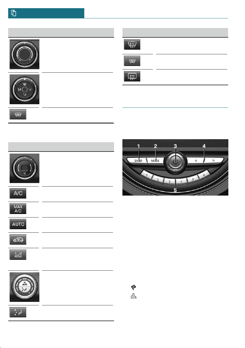
Automatic climate control
Button Function
Temperature.
Air conditioning.
Button Function
Defrost and defog the windows.
Windshield defroster.
Rear window defroster.
Infotainment
Radio
Control elements
30
Maximum cooling.
AUTO program.
Recirculated-air mode.
Automatic recirculated-air
control AUC/recirculatedair mode.
Control the air flow, manual.
Air distribution, manual.
Online Edition for Part no. 01402723718 - VI/18
1 Change waveband
2 Changing the entertainment source
3 Sound output on/off, volume
4 Change station/track
5 Programmable memory buttons
Navigation destination entry
Entering a destination via address
State/province
1. "Navigation"
2. "Enter address"
3. "State/Province?"
4. Move the Controller to the right to se-
lect the state from the list.
Page 31

Your MINI at a glance QUICK REFERENCE
Entering the address
The address can be entered in any order.
Example: entering the address via the town/
city
1. "City/Postal code?"
2. Enter the town/city.
The list is narrowed down further with
each entry.
3. Select the symbol.
4. Select a town/city from the list.
5. If necessary, enter the street.
6. Select the street as you would the town/
city.
7. If necessary, enter a house number.
8. Select the symbol.
9. Select a house number or range of house
numbers from the list.
Starting destination guidance
"Start guidance"
If only the town/city was entered: destina-
tion guidance is started to the town/city
center.
6. To perform additional steps on the mo-
bile phone, refer to the mobile phone
owner's manual: e.g., search for or connect the Bluetooth device or a new device.
The Bluetooth name of the vehicle appears on the mobile phone display. Select the Bluetooth name of the vehicle.
7. Depending on the mobile device, a con-
trol number is displayed or the control
number must be entered.
– Compare the control number dis-
played on the Control Display with
the control number on the display of
the device.
Confirm the control number on the
device and on the Control Display.
– Enter and confirm the same control
number on the device and via the
Central Information Display (CID).
The device is connected and displayed
in the device list.
The mobile phone is connected and will appear at the top of the list of mobile phones.
Using the phone
Pairing the mobile phone
After the mobile phone is paired once with
the vehicle, the mobile phone can be operated using the Central Information Display
(CID), the steering wheel buttons and spoken instructions.
1. "My MINI"
2. "System settings"
3. "Mobile devices"
4. "Connect new device"
The Bluetooth name of the vehicle is
displayed on the Control Display.
5. Select the functions for which the mo-
bile phone is to be used.
Online Edition for Part no. 01402723718 - VI/18
Accepting a call
Incoming call can be accepted via the Central Information Display (CID) or the button
on the steering wheel.
Via the Central Information Display (CID)
"Accept"
Via the button on the steering wheel
Press button.
Via the instrument cluster
Use the OK button on the steering wheel to
select: "Accept"
31
Page 32

QUICK REFERENCE Your MINI at a glance
Dialing a number
1. "Communication"
2. "Dial number"
3. Select the numbers individually.
4. Select the symbol.
If connection is to be set up via the additional phone:
1. Press button.
2. "Call via"
Apple CarPlay preparation
Concept
CarPlay allows certain functions of a compatible Apple iPhone to be used via Siri
voice operation and the Central Information
Display (CID).
Functional requirements
– Compatible iPhone.
iPhone 5 or later with iOS 7.1 or later.
– Corresponding mobile wireless contract.
– Bluetooth, WiFi, and Siri voice opera-
tion are switched on on the iPhone.
Pairing iPhone with CarPlay
Pair iPhone via Bluetooth with the vehicle.
Select CarPlay as the function:
"Apple CarPlay"
The iPhone is connected to the vehicle and
displayed in the device list.
Refueling
Refueling
Fuel cap
1. Grasp the fuel filler flap at the rear edge
and open it.
2. Turn the fuel cap counterclockwise.
3. Place the fuel cap in the bracket at-
tached to the fuel filler flap.
Switching on Bluetooth and CarPlay
Via the Central Information Display (CID):
1. "My MINI"
2. "System settings"
3. "Mobile devices"
4. "Settings"
5. Select the following settings:
– "Bluetooth®"
– "Apple CarPlay"
32
Online Edition for Part no. 01402723718 - VI/18
Gasoline
For the best fuel efficiency, the gasoline
should be sulfur-free or very low in sulfur
content.
Refuel only with unleaded gasoline without
metallic additives.
Information on the recommended fuel grade
can be found in the Owner's Manual.
Page 33

Your MINI at a glance QUICK REFERENCE
Wheels and tires
Tire inflation pressure specifications
For 5-door models:
The tire inflation pressure values can be
found on the sign on the door pillar.
Electronic oil measurement
Requirements
A current measured value is available after
approx. 30 minutes of driving. During a
shorter trip, the status of the last, sufficiently long trip is displayed.
Displaying the engine oil level
Via the Central Information Display (CID):
1. "My MINI"
2. "Vehicle status"
3. "Engine oil level"
The engine oil level is displayed.
Adding engine oil
General information
Switch off the ignition and safely park the
vehicle before engine oil is added.
Adding
For 3-door models:
The tire inflation pressure values can be
found on the sign on the door pillar.
Checking the tire inflation pressure
Regularly check the tire inflation pressure
and correct it as needed:
– At least twice a month.
– Before embarking on an extended trip.
After correcting the tire inflation
pressure
Reinitialize the Flat Tire Monitor.
Reset the Tire Pressure Monitor.
Online Edition for Part no. 01402723718 - VI/18
Only add engine oil when the message is
displayed in the instrument cluster.
Observe the quantity to be added in the
message.
Take care not to add too much engine oil.
Observe recommended engine oil types.
33
Page 34

QUICK REFERENCE Your MINI at a glance
Providing assistance
Hazard warning flashers
The button is located above the Control Display.
Breakdown assistance
MINI Roadside Assistance
This service can be reached around the
clock in many countries.
1. "MINI Connected"
2. "MINI Assist"
3. "MINI Roadside Assistance"
The contact to the MINI Roadside Assistance is established.
A telephone number is displayed, if
needed. Select to dial the telephone
number on a connected mobile phone.
34
Online Edition for Part no. 01402723718 - VI/18
Page 35

Your MINI at a glance QUICK REFERENCE
Online Edition for Part no. 01402723718 - VI/18
35
Page 36

36
Online Edition for Part no. 01402723718 - VI/18
Page 37

AT A GLANCE
Cockpit ........................................................................................................ 38
Central Information Display (CID) ...................................................... 42
Voice activation system ......................................................................... 51
General settings ....................................................................................... 54
Owner's Manual media ........................................................................... 66
Online Edition for Part no. 01402723718 - VI/18
37
Page 38

AT A GLANCE Cockpit
Cockpit
Vehicle features and options
This chapter describes all standard, countryspecific and optional features offered with
the series. It also describes features that are
not necessarily available in your vehicle,
e. g., due to the selected options or country
versions. This also applies to safety-related
functions and systems. When using these
functions and systems, the applicable laws
and regulations must be observed.
In the vicinity of the steering wheel
1 Power windows 85
2 Exterior mirror operation 95
3 Buttons of the central locking sys-
tem 75
4 Lights
Front fog lights 150
Light switch 147
38
Online Edition for Part no. 01402723718 - VI/18
Lights off
Daytime running lights 149
Parking lights 147
Low beams 147
Page 39

Cockpit AT A GLANCE
Automatic headlight control 148
Cornering light 149
High-beam Assistant 149
Instrument lighting 151
5 Steering wheel buttons, left
Camera-based cruise control
on/off 179
Cruise control on/off 185
Cruise control: store speed
Pausing, continuing cruise
control
Cruise control: increase speed
Cruise control: reduce speed
Camera-based cruise control:
reduce distance
Roadside parking lights 148
Onboard Computer 138
7 Instrument cluster 128
8 Steering column stalk, right
Windshield wipers 114
Rain sensor 115
Cleaning windows 112
Rear window wiper 113
Clean the rear window 113
9 Steering wheel buttons, right
Voice activation 51
Telephone
Camera-based cruise control:
increase distance
6 Steering column stalk, left
Turn signal 110
High beams, headlight flasher 110
High-beam Assistant 149
Online Edition for Part no. 01402723718 - VI/18
Confirm the selection 138
Move selection up 138
Move selection down 138
Increase volume
Reduce volume
10 Horn, entire surface
39
Page 40

AT A GLANCE Cockpit
11 Adjust the steering wheel 97 12 Unlock hood 268
In the vicinity of the center console
1 Hazard warning system 289
Intelligent Safety 164
2 Control Display 42
3 Radio/Multimedia
4 Glove compartment 214
5 Climate control 199
6 PDC Park Distance Con-
trol 187
Rearview camera 190
Parking assistant 194
Auto Start/Stop func-
tion 107
40
Online Edition for Part no. 01402723718 - VI/18
Start/stop the engine and
switch the ignition on/
off 104
DSC Dynamic Stability Control
174
MINI Driving Modes
switch 176
7 Steptronic transmission selector
lever 119
Manual transmission selector
lever 118
8 Controller with buttons 45
Controller with buttons 45
9 Parking brake 109
Page 41

In the vicinity of the roofliner
Cockpit AT A GLANCE
1 Emergency Request,
SOS 290
2 Indicator light, front-seat pas-
senger airbag 156
3 Reading lights 151
Online Edition for Part no. 01402723718 - VI/18
4 Ambient light 151
5 Panoramic glass sunroof 87
6 Interior lights 151
41
Page 42

AT A GLANCE Central Information Display (CID)
Central Information Display (CID)
Vehicle features and options
This chapter describes all standard, countryspecific and optional features offered with
the series. It also describes features that are
not necessarily available in your vehicle,
e. g., due to the selected options or country
versions. This also applies to safety-related
functions and systems. When using these
functions and systems, the applicable laws
and regulations must be observed.
Concept
The Central Information Display (CID) combines the functions of a multitude of
switches. These functions can be operated
via the Controller or touchscreen.
Safety information
WARNING
Operating the integrated information systems and communication devices while
driving can distract from traffic. It is possible to lose control of the vehicle. There is
a risk of an accident. Only use the systems
or devices when the traffic situation allows. As warranted, stop and use the systems and devices while the vehicle is stationary.
Input and display
Letters and numbers
Depending on the menu, you can switch between entering upper and lower case letters
and numbers:
Symbol Function
or
Insert blank space.
Use voice activation.
Confirm entry.
Without navigation system
Select the symbol.
Entry comparison
When entering names and addresses, the
choice is narrowed down with every letter
entered and letters may be added automatically.
Entries are continuously compared with
data stored in the vehicle.
– Only those letters are offered during en-
try for which data is available.
– Destination search: place names can be
entered in all languages that are available on the Control Display.
Activating/deactivating the
functions
Several menu items are preceded by a
checkbox. The checkbox indicates whether
the function is activated or deactivated. Selecting the menu item activates or deactivates the function.
Change between capital and
lower-case letters.
42
Online Edition for Part no. 01402723718 - VI/18
Page 43

Central Information Display (CID) AT A GLANCE
Function is activated.
Function is deactivated.
Status information
General information
The status field can be found in the upper
area of the Control Display. Status information is displayed in the form of symbols.
Radio
Symbol Meaning
HD Radio station is being re-
ceived.
Satellite radio is switched on.
Telephone
Symbol Meaning
Incoming or outgoing call.
Missed call.
Signal strength of cellular net-
work.
Symbol flashes: network search.
Cellular network is not available.
Roaming is active.
SMS text message received.
Message received.
Reminder.
Sending not possible.
Entertainment
Symbol Meaning
Bluetooth audio.
USB audio interface.
Mobile phone audio interface.
Additional symbols
Symbol Meaning
Check Control message.
The sound output has been
switched off.
Encrypted connection not ac-
tive.
Request for the current vehicle
position.
Checking the current vehicle po-
sition.
Split screen
General information
Additional information can be displayed on
the right side of the split screen, for instance information from the Onboard Computer.
In the divided screen view, the so-called
split screen, this information remains visible even when switching to another menu.
Switching the split screen on/off
1. Press button.
2. "Split screen"
Online Edition for Part no. 01402723718 - VI/18
43
Page 44

AT A GLANCE Central Information Display (CID)
Selecting the display
The display can be selected in menus,
where the split screen is supported.
1. Move the Controller to the right until
the split screen is selected.
2. Press the Controller.
3. Select the desired setting.
Specifying the number of displays
It is possible to specify the number of displays.
1. Move the Controller to the right until
the split screen is selected.
2. Press the Controller.
3. "Personalize menu"
4. Select the desired setting.
5. Move the Controller to the left.
Control elements
Overview
Control Display
General information
To clean the Control Display, follow the care
instructions, refer to page 301.
In the case of very high temperatures on
the Control Display, for instance due to intense solar radiation, the brightness may be
reduced down to complete deactivation.
Once the temperature is reduced, for instance through shade or air conditioning,
the normal functions are restored.
Safety information
NOTICE
Objects in the area in the front of the Control Display can shift and damage the Control Display. There is a risk of damage to
property. Do not place objects in the area
in front of the Control Display.
Switching on/off automatically
The Control Display is switched on automatically after unlocking.
In certain situations, the Control Display is
switched off automatically, for instance if
no operation is performed on the vehicle for
several minutes.
1 Control Display with touchscreen
2 Controller with buttons and, depending
on the equipment version, with touchpad
44
Online Edition for Part no. 01402723718 - VI/18
Switching on/off manually
The Control Display can also be switched off
manually.
1. Press button.
2. "Turn off control display"
Press the Controller or any button on the
Controller to switch it back on again.
Page 45

Central Information Display (CID) AT A GLANCE
Controller with navigation system
General information
The buttons can be used to open the menus
directly. The Controller can be used to select menu items and enter the settings.
Some functions of the Central Information
Display (CID) can be operated using the
touchpad on the Controller, refer to
page 49:
Operation
– Turn.
– Press.
Buttons on the Controller
Button Function
Press once: call up main menu.
Press twice: open recently used
menus.
Open the Communication menu.
Open the Media/Radio menu.
Open destination input menu for
navigation.
Open navigation map.
Open the previous display.
Open the Options menu.
Controller without navigation
system
– Move in four directions.
Online Edition for Part no. 01402723718 - VI/18
General information
The buttons can be used to open the menus
directly. The Controller can be used to select menu items and enter the settings.
Some functions of the Central Information
Display (CID) can be operated using the
touchpad on the Controller, refer to
page 49:
Operation
– Turn.
45
Page 46

AT A GLANCE Central Information Display (CID)
Button Function
Operating with the Controller
– Press.
Opening the main menu
Press the button.
– Move in two directions.
Open the previous display.
Open the Options menu.
Buttons on the Controller
Button Function
Press once: call up main menu.
Press twice: open recently used
menus.
Open the Communication menu.
Open the Media/Radio menu.
46
Online Edition for Part no. 01402723718 - VI/18
The main menu is displayed.
All Central Information Display (CID) func-
tions can be called up via the main menu.
Selecting menu items
Highlighted menu items can be selected.
1. Turn the Controller until the desired
menu item is highlighted.
2. Press the Controller.
Page 47

Central Information Display (CID) AT A GLANCE
Changing between displays
After a menu item is selected, for instance
"System settings", a new display appears.
– Move the Controller to the left.
Closes the current display and shows the
previous display.
– Press button.
The previous display opens.
– Move the Controller to the right.
New display is opened.
An arrow indicates that additional displays
can be opened.
Opening recently used menus
The recently used menus can be displayed.
Press button twice.
Opening the Options menu
Press button.
The "Options" menu is displayed.
The Options menu consists of various areas:
– Screen settings, for instance "Split
screen".
– Control options for the selected main
menu, for instance for "Media/Radio".
– If applicable, further operating options
for the selected menu, for instance "Save
station".
Changing settings
Settings, such as brightness, can be entered.
1. "My MINI"
2. "System settings"
3. "Displays"
4. "Control display"
5. "Brightness at night"
6. Turn the Controller until the desired set-
ting is displayed.
7. Press the Controller.
Entering letters and numbers
Input
1. Turn the Controller: select letters or
numbers.
2. : confirm entry.
Deleting
Symbol Function
Press the Controller: delete
letters or number.
or
Hold the Controller down: delete all letters or numbers.
Using alphabetical lists
For alphabetical lists with more than 30 entries, the letters for which there is an entry
are displayed at the left edge.
1. Turn the Controller to the left or right
quickly.
All letters for which there are entries
are displayed on the left edge.
2. Select the first letter of the desired en-
try.
The first entry of the selected letter is
displayed.
Operating via touchscreen
General information
The Control Display is equipped with a
touchscreen.
Online Edition for Part no. 01402723718 - VI/18
47
Page 48

AT A GLANCE Central Information Display (CID)
Touch screen with your fingers. Do not use
any objects.
Opening the main menu
Tap on symbol.
The main menu is displayed.
All Central Information Display (CID) func-
tions can be called up via the main menu.
Selecting menu items
Tap desired menu item.
2. Tap on symbol.
Changing settings
Settings such as brightness can be changed
via the touchscreen.
1. "My MINI"
2. "System settings"
3. "Displays"
4. "Control display"
5. "Brightness at night"
6. To create the desired setting:
– Slide in the selected field to the right
or left, until the desired setting is
displayed.
– , Tap on symbol.
Entering letters and numbers
Input
1. Touch the symbol on the touch-
screen.
A keyboard is displayed in the Control
Display.
2. Enter letters and numbers.
Changing between displays
After a menu item is selected, a new display
opens.
An arrow indicates that additional displays
can be opened.
– Swipe to the left.
– Tap arrow.
New display is opened.
Opening recently used menus
1. Tap on symbol.
48
Online Edition for Part no. 01402723718 - VI/18
Deleting
Symbol Function
Tapping the symbol: delete the
letter or number.
Tapping and holding the symbol
for an extended period: delete all
letters or numbers.
Operating navigation map
The navigation map can be moved with the
touchscreen.
Page 49

Central Information Display (CID) AT A GLANCE
Function Operation
Enlarge/shrink
map.
Drag in or out with the
fingers.
Touchpad
General information
Some functions of the Central Information
Display (CID) can be operated using the
touchpad on the Controller:
Selecting functions
1. "My MINI"
2. "System settings"
3. "Touchpad"
4. Select the desired function.
– "Speller": enter letters and numbers.
– "Map": using the map.
– "Search fields": write letters without
selecting the list field.
– "Audio feedback": pronounces en-
tered letters and numbers.
Entering letters and numbers
Entering letters requires some practice at
the beginning. When entering, pay attention to the following:
– The system distinguishes between up-
per and lower-case letters and numbers.
To make entries, it may be necessary to
change between upper and lower-case
letters, numbers and characters, refer to
page 47.
– Enter characters as they are displayed
on the Control Display.
– Always enter associated characters,
such as accents or periods so that the
letter can be clearly recognized. The set
language determines what input is pos-
sible. Where necessary, enter special
characters via the Controller.
– To delete a character, swipe to the left
on the touchpad.
– To enter a blank space, swipe to the
right in the center of the touchpad.
– To enter a hyphen, swipe to the right in
the upper area of the touchpad.
– To enter an underscore, swipe to the
right in the lower area of the touchpad.
Using the map
The map in the navigation system can be
moved via the touchpad.
Function Operation
Move map. Swipe in the appropriate
direction.
Enlarge/
shrink map.
Display menu. Tap once.
Drag in or out on the
touchpad with fingers.
Programmable memory buttons
General information
The Central Information Display (CID) functions can be stored on the programmable
memory buttons and called up directly, for
instance radio stations, navigation destinations, phone numbers and menu entries.
Settings are stored for the driver profile
currently used.
Storing a function
1. Select the function via the Central Infor-
mation Display (CID).
2. Press and hold the desired but-
ton, until a signal sounds.
Online Edition for Part no. 01402723718 - VI/18
49
Page 50

AT A GLANCE Central Information Display (CID)
Running a function
Press button.
The function will work immediately.
This means, for instance that the number is
dialed when a phone number is selected.
Displaying the key assignment
Touch buttons with finger. Do not wear
gloves or use objects.
The button assignment is displayed at the
top edge of screen.
Deleting the button assignments
1. Press buttons 1 and 6 simultaneously
for approx. 5 seconds.
2. "OK"
50
Online Edition for Part no. 01402723718 - VI/18
Page 51

Voice activation system AT A GLANCE
Voice activation system
Vehicle features and options
This chapter describes all standard, countryspecific and optional features offered with
the series. It also describes features that are
not necessarily available in your vehicle,
e. g., due to the selected options or country
versions. This also applies to safety-related
functions and systems. When using these
functions and systems, the applicable laws
and regulations must be observed.
Concept
Most functions displayed on the Control
Display can be operated by voice commands
via the voice activation system. The system
supports you with announcements during
input.
General information
– Functions that can only be used when
the vehicle is stationary can only be operated via the voice activation system to
a limited extent.
– The system uses a special microphone
on the driver's side.
– ›...‹ in the Owner's Manual denotes ver-
bal instructions to use with the voice activation system.
– Say the commands, numbers, and letters
smoothly and with normal volume, emphasis, and speed.
– Always say commands in the language
of the voice activation system.
Functional requirements
Via the Control Display, set a language that
is also supported by the voice activation
system so that the spoken commands can be
identified.
To set the language, refer to page 54.
Using the voice activation system
Activating the voice activation
system
1. Press the button on the steering
wheel.
2. Wait for the signal.
3. Say the command.
This symbol in the instrument cluster
indicates that the voice activation system is
active.
No other commands may be available. In
this case, operate the function via the Central Information Display (CID).
Terminating the voice activation
system
Press the button on the steering
wheel or ›Cancel‹.
Using a smartphone via voice
activation
A smartphone connected to the vehicle can
be used via voice activation.
Online Edition for Part no. 01402723718 - VI/18
51
Page 52

AT A GLANCE Voice activation system
Activate voice command response on the
smartphone for this purpose.
1. Press and hold the button on
the steering wheel for approx. 3 seconds.
Voice command response is activated on
the smartphone.
2. Release the button.
If activation is successful, a confirmation appears on the Control Display.
If it was not possible to activate voice command response, the list of Bluetooth devices
appears on the Control Display.
Possible commands
General information
Most menu items on the Control Display can
be voiced as commands.
Commands from other menus can also be
spoken.
You may select list entries such as phone
list entries via voice activation. Read these
list entries out loud exactly as they are
shown in the respective list.
Displaying possible commands
The following is displayed in the top area of
the Control Display:
– Some possible commands for the current
menu.
– Some possible commands from other
menus.
– Status of the voice recognition.
– Encrypted connection is not availa-
ble.
Help on the voice activation system
– To have information on the operating
principle of the voice activation system
read out loud: ›General information on
voice control‹.
– To have help for the current menu read
out loud: ›Help‹.
Example: opening the tone settings
The commands of the menu items are spoken just as they are selected via the Controller.
1. Switch on the Entertainment sound out-
put, if needed.
2. Press button on the steering
wheel.
3. ›Media and radio‹
4. ›Tone‹
Settings
Setting the voice dialog
You can set the system to use standard dialog or a short version.
The short version of the voice dialog plays
back short messages in abbreviated form.
1. "My MINI"
2. "System settings"
3. "Language"
4. "Speech mode:"
5. Select the desired setting.
52
Online Edition for Part no. 01402723718 - VI/18
Page 53

Voice activation system AT A GLANCE
Activating voice recognition via
the server
The voice recognition feature via the server
provides a dictation function and a natural
method of entering destinations while improving the quality of voice recognition. To
use the functions, data is transmitted to a
service provider via an encrypted connection and stored locally there.
1. "My MINI"
2. "System settings"
3. "Language"
4. "Server speech recognition"
Speaking during voice output
It is possible to answer during inquiries of
the voice activation system. The function
can be deactivated if inquiries are often undesirably interrupted, for instance due to
background noise or talking.
1. "My MINI"
2. "System settings"
3. "Language"
4. "Speaking during voice output"
Setting the language
The language to be used for voice activation
and system announcements can be set.
Adjusting the volume
Turn the volume button during the spoken
instructions until the desired volume is set.
– The volume remains constant even if the
volume of other audio sources is
changed.
– The volume is stored for the profile cur-
rently used.
Information on Emergency Requests
Do not use the voice activation system to
initiate an Emergency Request. In stressful
situations, the voice and vocal pitch can
change. This can unnecessarily delay the establishment of a phone connection.
Instead, use the SOS button, refer to
page 290, close to the interior mirror.
Environmental conditions
– Keep the doors, windows, and glass sun-
roof closed to prevent noise interference.
– Avoid making other noise in the vehicle
while speaking.
1. "My MINI"
2. "System settings"
3. "Language"
4. "Language:"
5. Select the desired language.
Online Edition for Part no. 01402723718 - VI/18
53
Page 54

AT A GLANCE General settings
General settings
Vehicle features and options
This chapter describes all standard, countryspecific and optional features offered with
the series. It also describes features that are
not necessarily available in your vehicle,
e. g., due to the selected options or country
versions. This also applies to safety-related
functions and systems. When using these
functions and systems, the applicable laws
and regulations must be observed.
Language
Setting the language
Via the Central Information Display (CID):
1. "My MINI"
2. "System settings"
3. "Language"
4. "Language:"
5. Select the desired setting.
The setting is stored for the driver profile
currently used.
Setting the voice dialog
Voice dialog for the voice activation system,
refer to page 52.
Time
3. "Date and time"
4. "Time zone:"
5. Select the desired setting.
The setting is stored for the driver profile
currently used.
Setting the time
Via the Central Information Display (CID):
1. "My MINI"
2. "System settings"
3. "Date and time"
4. "Time:"
5. Turn the Controller until the desired
hours are displayed.
6. Press the Controller.
7. Turn the Controller until the desired mi-
nutes are displayed.
8. Press the Controller.
Setting the time format
Via the Central Information Display (CID):
1. "My MINI"
2. "System settings"
3. "Date and time"
4. "Time format:"
5. Select the desired setting.
The setting is stored for the driver profile
currently used.
Setting the time zone
Via the Central Information Display (CID):
1. "My MINI"
2. "System settings"
54
Online Edition for Part no. 01402723718 - VI/18
Page 55

General settings AT A GLANCE
Date
Setting the date
Via the Central Information Display (CID):
1. "My MINI"
2. "System settings"
3. "Date and time"
4. "Date:"
5. Turn the Controller until the desired day
is displayed.
6. Press the Controller.
7. Make the settings for the month and
year.
Setting the date format
Via the Central Information Display (CID):
1. "My MINI"
2. "System settings"
3. "Date and time"
4. "Date format:"
5. Select the desired setting.
The setting is stored for the driver profile
currently used.
Setting the units of measurement
You can set the units of measurement for
some values, for example, fuel consumption,
distances and temperature.
Via the Central Information Display (CID):
1. "My MINI"
2. "System settings"
3. "Units"
4. Select the desired menu item.
5. Select the desired setting.
The setting is stored for the driver profile
currently used.
Activating/deactivating the display of the current vehicle position
Concept
If vehicle location has been activated, the
current vehicle position can be displayed in
the MINI Connected app.
Activating/deactivating
Via the Central Information Display (CID):
1. "My MINI"
2. "Vehicle settings"
3. "Vehicle tracking"
4. "Vehicle tracking"
5. Select the desired setting.
Activating/deactivating popup windows
For some functions, popup windows are displayed automatically on the Control Display.
Some of these popup windows can be activated or deactivated.
Via the Central Information Display (CID):
1. "My MINI"
2. "System settings"
3. "Pop-ups"
4. Select the desired setting.
The setting is stored for the driver profile
currently used.
Online Edition for Part no. 01402723718 - VI/18
55
Page 56

AT A GLANCE General settings
Control Display
Brightness
Via the Central Information Display (CID):
1. "My MINI"
2. "System settings"
3. "Displays"
4. "Control display"
5. "Brightness at night"
6. Turn the Controller until the desired
brightness is set.
7. Press the Controller.
The setting is stored for the driver profile
currently used.
Depending on the light conditions, the
brightness settings may not be clearly visible.
Screensaver
If no entries are made via the Central Information Display (CID), a screensaver can be
displayed after an adjustable time.
Via the Central Information Display (CID):
Messages
Concept
The menu centrally displays all messages arriving in the vehicle in list form.
General information
The following messages can be displayed:
– Traffic messages.
– Check Control messages.
– Communication messages, for example
e-mails, SMS text messages or remind-
ers.
– Service requirements messages.
Messages are additionally displayed in the
status field.
Retrieving messages
Via the Central Information Display (CID):
1. "Notifications"
2. Select the desired message.
The respective menu is opened, where the
message is displayed.
1. "My MINI"
2. "System settings"
3. "Displays"
4. "Control display"
5. "Screensaver"
6. Select the desired setting.
The setting is stored for the driver profile
currently used.
56
Online Edition for Part no. 01402723718 - VI/18
Deleting messages
All messages, except Check Control messages, can be deleted from the list. Check
Control messages are displayed as long as
they are relevant.
Via the Central Information Display (CID):
1. "Notifications"
2. Select the desired message.
3. Press button.
4. "Delete this notification" or "Delete all
notifications"
Settings
The following settings can be adjusted:
Page 57

General settings AT A GLANCE
– Select the applications, from which mes-
sages will be permitted.
– Sort the messages according to date or
priority.
Via the Central Information Display (CID):
1. "My MINI"
2. "System settings"
3. "Notifications"
4. Select the desired setting.
Data protection
Data transfer
Concept
The vehicle offers various functions which
require data to be transferred to MINI or a
service provider. The data transfer can be
deactivated for some functions.
General information
With data transfer deactivated, the respective function cannot be used.
Only make these settings while stationary.
Activating/deactivating the data
transfer
Follow the instructions on the Control Display.
Via the Central Information Display (CID):
1. Switch on the ignition.
2. "My MINI"
3. "System settings"
4. "Data privacy"
5. Select the desired setting.
Deleting personal data in the
vehicle
Concept
Depending on the usage, the vehicle stores
personal data, such as stored radio stations.
This personal data can be permanently de-
leted via the Central Information Display
(CID).
General information
Depending on the vehicle equipment, the
following data is deleted:
– Driver profile settings.
– Stored radio stations.
– Stored programmable memory buttons.
– Travel and Onboard Computer informa-
tion.
– Music collection.
– Navigation, for instance stored destina-
tions.
– Phone book.
– Office data, for instance voice notes.
– Login accounts.
Altogether, the deletion of the data can take
up to 15 minutes.
Functional requirement
Data can only be deleted while stationary.
Deleting data
Heed and follow the instructions on the
Control Display.
Via the Central Information Display (CID):
1. Switch on the ignition.
2. "My MINI"
3. "System settings"
4. "Data privacy"
5. "Delete personal data"
Online Edition for Part no. 01402723718 - VI/18
57
Page 58

AT A GLANCE General settings
6. "Delete personal data"
7. "OK"
8. Exit and lock the vehicle.
After 15 minutes, the deletion process is
completed.
If not all of the data was deleted, repeat the
deletion.
Canceling deletion
Start the engine to cancel deletion of the
data.
Connections
Concept
Various connection types are available for
using mobile devices in the vehicle. The
connection type to select depends on the
mobile device and the desired function.
General information
The following overview shows possible
functions and the suitable connection types
for them. The scope of functions depends on
the mobile device.
Function Connec-
tion type
Making calls via the handsfree system.
Using phone functions via
the Central Information Display (CID).
Using the smartphone Office functions.
Playing music from the
smartphone or the audio
player.
Bluetooth.
Bluetooth
or USB.
Function Connec-
tion type
Using compatible apps via
the Central Information Display (CID).
USB storage device:
Exporting and importing
driver profiles.
Performing software up-
dates.
Playing music.
Playing videos from the
smartphone or the USB storage device.
Using Apple CarPlay apps
via the Central Information
Display (CID) and voice operation.
The following connection types require onetime pairing with the vehicle:
– Bluetooth.
– Apple CarPlay
Paired devices are automatically recognized
later on and connected to the vehicle.
Bluetooth
or USB.
USB.
USB.
Bluetooth
and WiFi.
Safety information
WARNING
Operating the integrated information systems and communication devices while
driving can distract from traffic. It is possible to lose control of the vehicle. There is
a risk of an accident. Only use the systems
or devices when the traffic situation allows. As warranted, stop and use the systems and devices while the vehicle is stationary.
58
Online Edition for Part no. 01402723718 - VI/18
Page 59

General settings AT A GLANCE
Compatible devices
General information
Information on mobile devices compatible
with the vehicle can be found at www.miniusa.com/bluetooth.
Malfunctions may occur with devices not
listed or deviating software versions.
Displaying the vehicle identification
number and software part number
When looking for compatible devices, you
may have to state the vehicle identification
number and the software part number.
These numbers can be displayed in the vehicle.
Via the Central Information Display (CID):
1. "My MINI"
2. "System settings"
3. "Mobile devices"
4. "Settings"
5. "Bluetooth® info"
6. "System information"
A software update, refer to page 64, can
be performed, if needed.
Bluetooth connection
Functional requirements
– Compatible device, refer to page 59,
with Bluetooth interface.
– The remote control is in the vehicle.
– The device is ready for operation.
– Bluetooth is activated on the device and
in the vehicle, refer to page 59.
– Bluetooth pre-settings, such as visibil-
ity, may be required on the device; refer
to the owner's manual of the device.
Switching on Bluetooth
Via the Central Information Display (CID):
1. "My MINI"
2. "System settings"
3. "Mobile devices"
4. "Settings"
5. "Bluetooth®"
Activating/deactivating telephone
functions
To use all supported functions of a mobile
phone, the following functions must be activated prior to pairing.
Via the Central Information Display (CID):
1. "My MINI"
2. "System settings"
3. "Mobile devices"
4. "Settings"
5. Select desired setting:
– "Office"
Activate function to transmit short
messages, e-mails, calendars, tasks,
notes, and reminders to the vehicle.
Costs can be incurred by transmitting all data to the vehicle.
– "Contact images"
Activate function to show the contact pictures.
6. Move the Controller to the left.
Pairing the mobile device with the
vehicle
Via the Central Information Display (CID):
1. "My MINI"
2. "System settings"
3. "Mobile devices"
4. "Connect new device"
Online Edition for Part no. 01402723718 - VI/18
59
Page 60

AT A GLANCE General settings
5. Select the functions for which the de-
vice will be used:
– "Telephone"
– "Bluetooth® audio"
– "Apps"
– "Apple CarPlay"
The Bluetooth name of the vehicle is
displayed on the Control Display.
6. Search for Bluetooth devices in the vi-
cinity of the mobile device.
The Bluetooth name of the vehicle ap-
pears on the mobile device display.
Select the Bluetooth name of the vehi-
cle.
7. Depending on the mobile device, a con-
trol number is displayed or the control
number must be entered.
– Compare the control number dis-
played on the Control Display with
the control number on the display of
the device.
Confirm the control number on the
device and on the Control Display.
– Enter and confirm the same control
number on the device and via the
Central Information Display (CID).
The device is connected and displayed
in the device list.
If connection was not successful: Frequently Asked Questions, refer to page 60.
Frequently asked questions
All requirements are met and all required
steps were completed in the specified order.
Despite that, the mobile device does not
function as expected.
In this case, the following explanations can
help:
Why could the mobile phone not be paired
or connected?
– There are too many Bluetooth devices
connected to the mobile phone or vehicle.
In the vehicle, delete Bluetooth connections with other devices.
Delete all known Bluetooth connections
from the device list on the mobile phone
and start a new device search.
– The mobile phone is in power-save mode
or has only a limited remaining battery
life.
Charge mobile phone.
Why does the mobile phone no longer react?
– The applications on the mobile phone do
not function anymore.
Switch the mobile phone off and on
again.
– Possibly too high or too low ambient
temperatures for mobile phone operation.
Do not subject the mobile phone to extreme ambient temperatures.
Why can phone functions not be used via
the Central Information Display (CID)?
– The mobile phone may not be properly
configured, for instance as Bluetooth audio device.
Connect the mobile phone with the telephone or additional phone function.
Why are no or not all phone book entries
displayed or why are they incomplete?
– Transmission of the phone book entries
is not yet complete.
– It is possible that only the phone book
entries of the mobile phone or the SIM
card are transmitted.
– It may not be possible to display phone
book entries with special characters.
– It may not be possible to transmit con-
tacts from social networks.
60
Online Edition for Part no. 01402723718 - VI/18
Page 61

General settings AT A GLANCE
– The number of phone book entries to be
stored is too high.
– Data volume of the contact too large, for
instance due to stored information such
as notes.
Reduce the data volume of the contact.
– A mobile phone is only connected as an
audio source.
Reconfigure the mobile phone and con-
nect it with the telephone or additional
phone function.
How can the phone connection quality be
improved?
– The strength of the Bluetooth signal on
the mobile phone can be adjusted, depending on the mobile phone.
– Insert mobile phone into the wireless
charging tray.
– Adjust the volume of the microphone
and loudspeakers separately.
If all points in this list have been checked
and the required function is still not available, contact the hotline, a dealer’s service
center or another qualified service center or
repair shop.
USB connection
General information
Mobile devices with a USB port are connected to the USB interface.
– Mobile phones.
– Audio devices with USB port, for in-
stance MP3 player.
– USB storage devices.
Common file systems are supported.
FAT32 and exFAT are the recommended
formats.
The following applications are possible:
– Exporting and importing driver profiles,
refer to page 79.
– Playing music files via USB audio.
– Playing videos via USB video.
– Loading of software updates, refer to
page 64.
Follow the following when connecting:
– Do not use force when plugging the con-
nector into the USB interface.
– Use a flexible adapter cable.
– Protect the USB storage device against
mechanical damage.
– Due to the large number of USB media
available on the market, it cannot be
guaranteed that every device is operable
on the vehicle.
– Do not expose USB media to extreme en-
vironmental conditions, such as very
high temperatures; refer to the owner's
manual of the device.
– Due to the many different compression
techniques, proper playback of the me-
dia stored on the USB storage device
cannot be guaranteed in all cases.
– A connected USB storage device will be
supplied with charging current via the
USB interface if the device supports
this.
– To ensure proper transmission of the
stored data, do not charge a USB storage
device via the onboard socket, when it
is connected to the USB interface.
– Depending on how the USB storage de-
vice is being used, settings may be re-
quired on the USB storage device, refer
to the owner's manual of the device.
Not compatible USB media:
– USB hard drives.
– USB hubs.
– USB memory card readers with multiple
inserts.
– HFS-formatted USB media.
– Devices such as fans or lamps.
Online Edition for Part no. 01402723718 - VI/18
61
Page 62

AT A GLANCE General settings
Functional requirement
Compatible device, refer to page 59, with
USB interface.
Connecting the device
Connect the USB storage device using a
suitable adapter cable to a USB interface,
refer to page 213.
The USB storage device is connected to the
vehicle and displayed in the device list.
Apple CarPlay preparation
Concept
CarPlay allows certain functions of a compatible Apple iPhone to be used via Siri
voice operation and the Central Information
Display (CID).
Functional requirements
– Compatible iPhone, refer to page 59.
iPhone 5 or later with iOS 7.1 or later.
– Corresponding mobile wireless contract.
– Bluetooth, WiFi, and Siri voice opera-
tion are switched on on the iPhone.
Switching on Bluetooth and CarPlay
Via the Central Information Display (CID):
1. "My MINI"
2. "System settings"
3. "Mobile devices"
4. "Settings"
5. Select the following settings:
– "Bluetooth®"
– "Apple CarPlay"
Pairing iPhone with CarPlay
Pairing an iPhone with the vehicle, refer to
page 59, via Bluetooth
Select CarPlay as the function:
"Apple CarPlay"
The iPhone is connected to the vehicle and
displayed in the device list, refer to
page 63.
Operation
For more information, refer to the
Integrated Owner's Manual in the vehicle or
the printed Owner's Manual for navigation,
entertainment, communication.
Frequently asked questions
All requirements are met and all required
steps were completed in the specified order.
Despite that, the mobile device does not
function as expected.
In this case, the following explanations can
help:
The iPhone has already been paired with
Apple CarPlay. When a new connection is
established, CarPlay can no longer be selected.
– Delete the iPhone concerned from the
device list.
– On the iPhone, delete the vehicle con-
cerned from the list of stored vehicles
under Bluetooth and under WiFi.
– Pair the iPhone as a new device.
If the steps listed have been carried out and
the required function is still not available:
contact the hotline, a dealer’s service center
or another qualified service center or repair
shop.
Managing mobile devices
General information
– After one-time pairing, the devices are
automatically recognized and recon-
nected when the ignition is switched on.
62
Online Edition for Part no. 01402723718 - VI/18
Page 63

General settings AT A GLANCE
– The data stored on the SIM card or in
the mobile phone are transferred to the
vehicle after recognition.
– For some devices, certain settings may
be necessary, for instance authorization,
see owner's manual of the device.
Displaying the device list
All devices paired and/or connected with
the vehicle are displayed in the device list.
Via the Central Information Display (CID):
1. "My MINI"
2. "System settings"
3. "Mobile devices"
A symbol indicates, for which function a device is used.
Symbol Function
"Telephone"
"Additional telephone"
"Bluetooth® audio"
"Apps"
"Apple CarPlay"
Configuring the device
Functions can be activated or deactivated
for paired and connected devices.
Via the Central Information Display (CID):
1. "My MINI"
2. "System settings"
3. "Mobile devices"
4. Select the desired device.
5. Select the desired setting.
If a function is assigned to a device, the
function will be deactivated where appropriate for a device that is already connected
and the device will be disconnected.
Disconnecting the device
The connection of the device to the vehicle
is disconnected.
The device remains paired and can be con-
nected again, refer to page 63.
Via the Central Information Display (CID):
1. "My MINI"
2. "System settings"
3. "Mobile devices"
4. Select device.
5. "Disconnect device"
Connecting the device
A disconnected device can be reconnected.
Via the Central Information Display (CID):
1. "My MINI"
2. "System settings"
3. "Mobile devices"
4. Select device.
5. "Connect device"
The functions that were assigned to the de-
vice before disconnecting are assigned to
the device when it is reconnected. If the de-
vice is already connected, these functions
are deactivated.
Deleting the device
Via the Central Information Display (CID):
1. "My MINI"
2. "System settings"
3. "Mobile devices"
4. Select device.
5. "Delete device"
The device is disconnected and removed
from the device list.
Online Edition for Part no. 01402723718 - VI/18
63
Page 64

AT A GLANCE General settings
Swapping the telephone and additional
phone
If two mobile phones are connected to the
vehicle, the functions of the phone and additional phone can be switched.
Via the Central Information Display (CID):
1. "My MINI"
2. "System settings"
3. "Mobile devices"
4. "Settings"
5. "Swap telephone/additional tel."
Software update
General information
The vehicle supports a large number of mobile devices, for instance mobile phones and
MP3 players. Software updates are available
for many of the supported devices. The vehicle is maintained up-to-date via regular
vehicle software updates.
Updates and related current information is
available on the Internet at www.mini.com/
update.
Displaying the installed software
version
The software version installed in the vehicle
is displayed.
Via the Central Information Display (CID):
1. "My MINI"
2. "System settings"
3. "Software update"
4. "Show current version"
If an update has been carried out before, select the desired version to display additional
information.
Updating software via USB
The software may only be updated when the
vehicle is stationary.
Via the Central Information Display (CID):
1. Store the file for the software update in
the main directory of a USB flash drive.
2. Connect the USB data storage to a USB
interface.
3. "My MINI"
4. "System settings"
5. "Software update"
6. "Update software"
7. "USB"
8. "Install software"
9. "OK"
10. Wait for the update to complete.
11. Confirm system restart.
Restoring the software version
The software version before the last software update and the version before the first
software update can be restored.
The software may only be restored when
the vehicle is stationary.
Via the Central Information Display (CID):
1. "My MINI"
2. "System settings"
3. "Software update"
4. "Restore software"
– "Previous version"
5.
The previous software version is restored.
– "Default software settings"
The first software version is restored.
6. "Remove software"
7. "OK"
64
Online Edition for Part no. 01402723718 - VI/18
Page 65

8. Wait for restore.
9. Confirm system restart.
General settings AT A GLANCE
Online Edition for Part no. 01402723718 - VI/18
65
Page 66

AT A GLANCE Owner's Manual media
Owner's Manual media
Vehicle features and options
This chapter describes all standard, countryspecific and optional features offered with
the series. It also describes features that are
not necessarily available in your vehicle,
e. g., due to the selected options or country
versions. This also applies to safety-related
functions and systems. When using these
functions and systems, the applicable laws
and regulations must be observed.
General information
You can use the following media formats to
call up the content in the Owner's Manual:
– Printed Owner's Manual, refer to
page 66.
– Integrated Owner's Manual in the vehi-
cle, refer to page 66.
Printed Owner's Manual
Concept
The printed Owner's Manual describes all
standard, country-specific, and optional features offered with the series.
General information
The Owner's Manual for Navigation, Entertainment, and Communication can be obtained as printed book from the service center.
Supplementary Owner's Manuals
Also follow the instructions of the Supplementary Owner's Manuals, which are included in addition to the onboard literature.
Integrated Owner's Manual in the vehicle
Concept
The Integrated Owner's Manual specifically
describes features and functions found in
the vehicle. The Integrated Owner's Manual
can be displayed on the Control Display.
Selecting the Owner's Manual
1. Press button.
2. "My MINI"
3. "Owner's Manual"
4. Select the required method of accessing
the contents.
Scrolling through the owner's
manual
Turn the Controller, until the next or previous contents are displayed.
Context help
General information
The section of the Owner's Manual relating
to the function that is currently selected
can be displayed directly.
66
Online Edition for Part no. 01402723718 - VI/18
Page 67

Owner's Manual media AT A GLANCE
Opening via Central Information
Display (CID)
Change directly to the Options menu from
the function on the Control Display:
1. Press button.
2. "Owner's Manual"
Opening when a Check Control
message is displayed
Directly from the Check Control message on
the Control Display:
"Owner's Manual"
Changing between a function and the
Owner's Manual
To switch from a function, for instance
radio, to the Owner's Manual on the Control
Display and to alternate between the two
displays:
1. Press the button.
2. "Owner's Manual"
3. Select the desired page in the Owner's
Manual.
Programmable memory buttons
General information
The Owner's Manual can be stored on the
programmable memory buttons and called
up directly.
Storing
1. Select the desired entry point via the
Central Information Display (CID):
– "Quick reference"
– "Search by pictures"
– "Keyword search"
– "Animations"
2. Press and hold the desired but-
ton, until a signal sounds.
Executing
Press button.
The Owner's Manual is displayed
immediately.
4. Press the button again to return to
last displayed function.
5. Press the button to return to the
page of the Owner's Manual displayed
last.
To alternate continuously between the last
displayed function and the last displayed
page of the Owner's Manual, repeat steps 4
& 5. Opens a new display every time.
Online Edition for Part no. 01402723718 - VI/18
67
Page 68

68
Online Edition for Part no. 01402723718 - VI/18
Page 69

CONTROLS
Opening and closing ................................................................................ 70
Seats, mirrors, and steering wheel ..................................................... 89
Transporting children safely ................................................................ 99
Driving ...................................................................................................... 104
Displays .................................................................................................... 128
Lights ........................................................................................................ 147
Safety ......................................................................................................... 153
Driving stability control systems ..................................................... 174
Driving comfort ...................................................................................... 179
Climate control ....................................................................................... 199
Interior equipment ................................................................................ 207
Storage compartments ......................................................................... 214
Cargo area ................................................................................................ 217
Online Edition for Part no. 01402723718 - VI/18
69
Page 70

CONTROLS Opening and closing
Opening and closing
Vehicle features and options
This chapter describes all standard, countryspecific and optional features offered with
the series. It also describes features that are
not necessarily available in your vehicle,
e. g., due to the selected options or country
versions. This also applies to safety-related
functions and systems. When using these
functions and systems, the applicable laws
and regulations must be observed.
Remote control
General information
The vehicle is supplied with two remote
controls with integrated key.
Each remote control contains a replaceable
battery. Replacing the battery, refer to
page 73.
You may set the button functions, depending on the vehicle equipment and country
version. Settings, refer to page 82.
The vehicle stores personal settings for every remote control. Driver profile, refer to
page 79.
The remote controls hold information about
required maintenance. Service data in the
remote control, refer to page 276.
To prevent possible locking in of the remote
control, take the remote control with you
when exiting the vehicle.
Safety information
WARNING
People or animals in the vehicle can lock
the doors from the inside and lock themselves in. In this case, the vehicle cannot
be opened from the outside. There is a risk
of injury. Take the remote control with
you so that the vehicle can be opened from
the outside.
WARNING
Unlocking from the inside is only possible
with special knowledge.
Persons who spend a lengthy time in the
vehicle while being exposed to extreme
temperatures are at risk of injury or death.
Do not lock the vehicle from the outside
when there are people in it.
WARNING
Unattended children or animals can cause
the vehicle to move and endanger themselves and traffic, for instance due to the
following actions:
– Pressing the Start/Stop button.
– Releasing the parking brake.
– Opening and closing the doors or
windows.
– Engaging selector lever position N.
– Using vehicle equipment.
There is a risk of accidents or injuries. Do
not leave children or animals unattended
in the vehicle. Take the remote control
with you when exiting and lock the vehicle.
70
Online Edition for Part no. 01402723718 - VI/18
Page 71

Opening and closing CONTROLS
Overview
1 Unlocking
2 Locking
3 Unlocking the tailgate
4 Panic mode
Unlocking
Press the button on the remote control.
Depending on the settings, refer to
page 82, the following access points are
unlocked.
– Driver's door and fuel filler flap.
Press the button on the remote control
again to unlock the other vehicle access
points.
– All doors, tailgate, and fuel filler flap.
In addition, the following functions are executed:
– Unlocking is confirmed by the turn sig-
nals and the horn. This function must be
activated in the settings, refer to
page 82.
– The settings stored in the driver profile,
refer to page 79, are applied.
– The interior lights, refer to page 151,
and the MINI logo projection are
switched on, provided that the interior
lights were not switched off manually.
– Depending on the settings, the welcome
light and headlight courtesy delay feature, refer to page 148, are switched on.
– Exterior mirrors folded through conven-
ient closing are folded open.
– The alarm system, refer to page 83, is
switched off.
The light functions may depend on the ambient brightness.
Convenient opening
Press and hold this button on the
remote control after unlocking.
The windows and the glass sunroof are
opened, as long as the button on the remote
control is pressed.
Locking
1. Close the driver's door.
2. Press button on the remote con-
trol.
The following functions are executed:
– All doors, the tailgate, and the fuel filler
flap are locked.
– Locking is confirmed by the turn signals
and the horn. This function must be activated in the settings, refer to
page 82.
– The alarm system, refer to page 83, is
switched on.
If the engine or ignition is still switched on
when you lock the vehicle, the vehicle horn
honks twice. In this case, the engine or ignition must be switched off by means of the
Start/Stop button.
Online Edition for Part no. 01402723718 - VI/18
71
Page 72

CONTROLS Opening and closing
With Comfort Access: convenient
closing
Safety information
WARNING
With convenient closing, body parts can
be jammed. There is a risk of injury. Make
sure that the area of movement of the
doors is clear during convenient closing.
Closing
Press and hold this button on the
remote control in the area close to
the vehicle.
The windows and the glass sunroof are
closed, as long as the button on the remote
control is pressed.
The exterior mirrors are folded in.
Switch on interior lights and
courtesy light
Press button on the remote control
with the vehicle locked.
The MINI logo projection is also switched
on.
These functions are not available if the interior lights were switched off manually.
The light functions may depend on the ambient brightness.
After locking, wait 10 seconds before pressing the button again.
Tailgate
Depending on the vehicle equipment and
country version, it is possible to specify
whether the tailgate can be unlocked with
the remote control and how the vehicle
doors will respond to this. Adjust the settings, refer to page 82.
Safety information
WARNING
Body parts can be jammed when operating
the tailgate. There is a risk of injury. Make
sure that the area of movement of the tailgate is clear during opening and closing.
NOTICE
The tailgate swings back and up when it
opens. There is a risk of damage to property. Make sure that the area of movement
of the tailgate is clear during opening and
closing.
NOTICE
Sharp-edged or pointed objects can hit the
windows and heat conductors while driving. There is a risk of damage to property.
Cover the edges and ensure that pointed
objects do not hit the windows.
Opening
Press and hold the button on the remote control for approx. 1 second.
The tailgate is unlocked and can be swung
upward.
General information
To avoid locking it in the vehicle, do not
place the remote control in the cargo area.
72
Online Edition for Part no. 01402723718 - VI/18
Panic mode
You can trigger the alarm system if you find
yourself in a dangerous situation.
Page 73

Opening and closing CONTROLS
– Press button on the remote con-
trol and hold for at least 3 seconds.
– Briefly press the button on the remote
control three times in succession.
To switch off the alarm: press any button.
Replacing the battery
1. Remove the integrated key from the re-
mote control, refer to page 75.
2. Slide the integrated key into the open-
ing and raise the cover.
The battery compartment is accessible.
3. Slide the integrated key in the cover of
the battery compartment and raise the
cover.
4. Push battery in the direction of the ar-
row using a pointed object and lift it
out.
5. Insert a type CR 2032 battery with the
positive side facing up.
6. Insert lid and cover.
7. Push the integrated key into the remote
control until it engages.
Have old batteries disposed of by a
dealer’s service center or another
qualified service center or repair
shop or take them to a collection point.
Additional remote controls
Additional remote controls are available
from a dealer’s service center or another
qualified service center or repair shop.
Loss of the remote controls
A lost remote control can be blocked and replaced by a dealer’s service center or another qualified service center or repair
shop.
Malfunction
General information
A Check Control message is displayed.
Remote control detection by the vehicle
may malfunction under the following circumstances:
Online Edition for Part no. 01402723718 - VI/18
73
Page 74

CONTROLS Opening and closing
– The battery of the remote control is dis-
charged. Replacing the battery, refer to
page 73.
– Interference of the radio connection
from transmission towers or other
equipment with high transmitting
power.
– Shielding of the remote control due to
metal objects.
Do not transport the remote control to-
gether with metal objects.
– Interference of the radio connection
from mobile phones or other electronic
devices in direct proximity to the remote control.
Do not transport the remote control together with electronic devices.
– Interference of radio transmission by a
charging process of mobile devices, for
instance charging of a mobile phone.
– The remote control is in direct proximity
of the wireless charging tray.
Place the remote control down at a dif-
ferent location.
In the case of interference, the vehicle can
be unlocked and locked from the outside
with the integrated key, refer to page 74.
Starting the engine via emergency
detection of the remote control
It is not possible to switch on the driveready state if the remote control has not
been detected.
Proceed as follows in this case:
1. Hold the remote control as shown
against the marked area on the steering
column. Pay attention to the display in
the instrument cluster.
2. If the remote control is detected:
Start the engine within 10 seconds.
If the remote control is not detected,
slightly change the position of the remote
control and repeat the procedure.
Frequently asked questions
What precautions can be taken to be able to
open a vehicle with an accidentally locked
in remote control?
– The options provided by the Remote
Services of the MINI Connected app include the ability to lock and unlock a vehicle.
This requires an active MINI Connected
contract and the MINI Connected app
must be installed on a smartphone.
– Unlocking the vehicle can be requested
via the MINI Connected Call Center.
An active MINI Connected contract is
required.
It is not possible to start the engine if the
remote control has not been detected.
74
Online Edition for Part no. 01402723718 - VI/18
Integrated key
General information
The driver's door can be locked and unlocked without remote control using the
integrated key.
Page 75

Opening and closing CONTROLS
Safety information
WARNING
Unlocking from the inside is only possible
with special knowledge.
Persons who spend a lengthy time in the
vehicle while being exposed to extreme
temperatures are at risk of injury or death.
Do not lock the vehicle from the outside
when there are people in it.
NOTICE
The door lock is permanently joined with
the door. The door handle can be moved.
When pulling the door handle with the
integrated key inserted, paint or the
integrated key can be damaged. There is a
risk of damage to property. Remove the
integrated key before pulling the outside
door handle.
Removing
To do this, slide the integrated key into
the opening from below and remove the
lid.
2. Unlock or lock the door lock using the
integrated key.
The other doors must be unlocked or locked
from the inside.
Alarm system
The alarm system is not switched on if the
vehicle is locked with the integrated key.
The alarm system is triggered when the
door is opened, if the vehicle has been unlocked via the door lock. In order to stop
this alarm, unlock vehicle with the remote
control or switch on the ignition, if needed,
through emergency detection of the remote
control, refer to page 73.
Press the button, arrow 1, and pull out the
integrated key, arrow 2.
Locking/unlocking via the door
lock
1. Remove lid on the door lock.
Online Edition for Part no. 01402723718 - VI/18
Buttons for the central locking system
General information
In the event of a severe accident, the vehicle is automatically unlocked. The hazard
warning system and interior lights come on.
75
Page 76

CONTROLS Opening and closing
Overview
Buttons for the central locking system.
Locking
Press the button with the front
doors closed.
– The fuel filler flap remains unlocked.
– The vehicle is not secured against theft
when locking.
Unlocking
Press button.
Opening
– Press button to unlock the doors
together, and then pull the door handle
above the armrest.
– Front doors: pull the door handle on the
door to open the door. The other doors
remain locked.
– Back doors: pull twice on the door han-
dle on the door to be opened; the first
time unlocks the door, the second time
opens it. The other doors remain locked.
Comfort Access
Concept
The vehicle can be accessed without activating the remote control.
All you need to do is to have the remote
control with you, such as in your pants
pocket.
The vehicle automatically detects the remote control when it is in close proximity
or in the car's interior.
General information
Comfort Access supports the following
functions:
– Unlocking and locking the vehicle.
– Convenient closing.
– Open the tailgate.
Functional requirements
– To lock the vehicle, the remote control
must be located outside of the vehicle
near the doors.
– The next unlocking and locking cycle is
not possible until after approx. 2 seconds.
Unlocking
76
On the driver's or front passenger's outer
door handle, press the button.
Depending on the settings, refer to
page 82, only the driver's door and the
Online Edition for Part no. 01402723718 - VI/18
Page 77

Opening and closing CONTROLS
fuel filler flap may be unlocked. Unlike
when unlocking with the remote control,
pressing the button on the outer door handle again does not unlock the other vehicle
access points. Rather, the vehicle is locked
again.
If a door of a locked vehicle was opened
from the inside via the door opener, pressing the button on the outer door handle first
locks the vehicle again. To unlock, the button on the outer door handle must be
pressed again.
This is the case whether the vehicle was
locked automatically after driving off or via
the central locking system button from the
inside.
Locking
Closing
Press and hold down the button on the driver's or front passenger's outer door handle.
In addition to locking, the windows and
glass sunroof will be closed.
The exterior mirrors are folded in.
Opening the tailgate
General information
If the tailgate is opened via Comfort Access,
locked doors are not unlocked.
To avoid locking it in the vehicle, do not
place the remote control in the cargo area.
On the driver's or front passenger's outer
door handle, press the button.
Convenient closing
Safety information
WARNING
With convenient closing, body parts can
be jammed. There is a risk of injury. Make
sure that the area of movement of the
doors is clear during convenient closing.
Online Edition for Part no. 01402723718 - VI/18
Safety information
WARNING
Body parts can be jammed when operating
the tailgate. There is a risk of injury. Make
sure that the area of movement of the tailgate is clear during opening and closing.
NOTICE
The tailgate swings back and up when it
opens. There is a risk of damage to property. Make sure that the area of movement
of the tailgate is clear during opening and
closing.
77
Page 78

CONTROLS Opening and closing
NOTICE
Sharp-edged or pointed objects can hit the
windows and heat conductors while driving. There is a risk of damage to property.
Cover the edges and ensure that pointed
objects do not hit the windows.
Opening
Press button next on tailgate.
The tailgate is unlocked and can be swung
upward.
Do not transport the remote control together with electronic devices.
Wet or snowy conditions may disrupt the
locking request recognition function on the
door handles.
In the case of a malfunction, unlock and
lock the vehicle using the buttons of the remote control or using the integrated key, refer to page 74.
Tailgate
General information
To avoid locking it in the vehicle, do not
place the remote control in the cargo area.
Depending on the vehicle equipment and
country version, it is possible to specify
whether the tailgate can be unlocked with
the remote control and how the vehicle
doors will respond to this. Adjust the settings, refer to page 82.
Malfunction
Remote control detection by the vehicle
may malfunction under the following circumstances:
– The battery of the remote control is dis-
charged. Replacing the battery, refer to
page 73.
– Interference of the radio connection
from transmission towers or other
equipment with high transmitting
power.
– Shielding of the remote control due to
metal objects.
Do not transport the remote control to-
gether with metal objects.
– Interference of the radio connection
from mobile phones or other electronic
devices in direct proximity to the remote control.
78
Online Edition for Part no. 01402723718 - VI/18
Safety information
WARNING
Body parts can be jammed when operating
the tailgate. There is a risk of injury. Make
sure that the area of movement of the tailgate is clear during opening and closing.
NOTICE
The tailgate swings back and up when it
opens. There is a risk of damage to property. Make sure that the area of movement
of the tailgate is clear during opening and
closing.
Page 79

Opening and closing CONTROLS
NOTICE
Sharp-edged or pointed objects can hit the
windows and heat conductors while driving. There is a risk of damage to property.
Cover the edges and ensure that pointed
objects do not hit the windows.
Opening and closing
Opening from the outside
With manual transmission:
With the vehicle stationary, press
the button in the driver's floor area twice in
quick succession.
Closing
Recessed grips on the interior trim of the
tailgate can be used to conveniently pull
down the tailgate.
– Without Comfort Access: unlock vehicle.
With Comfort Access: unlock the vehicle or have the remote control with you.
Press button next on tailgate.
– Press and hold button on the re-
mote control for approx. 1 second.
Depending on the setting, the doors may
also be unlocked. Unlocking with the remote control, refer to page 72.
The tailgate is unlocked and can be swung
upward.
Opening from the inside
With Steptronic transmission:
With the vehicle stationary, press
the button in the driver's floor area.
If the vehicle is locked, selector lever posi-
tion P must be engaged first.
Online Edition for Part no. 01402723718 - VI/18
Driver profile
Concept
In the driver profiles, individual settings for
several drivers can be stored and called up
again when required.
General information
There are three driver profiles with which
personal vehicle settings can be stored. Every remote control has one of these driver
profiles assigned.
If the vehicle is unlocked using a remote
control, the assigned personal driver profile
will be activated. All settings stored in the
driver profile are automatically applied.
If several drivers use their own remote control, the vehicle will adjust the personal settings during unlocking. These settings are
also restored, if the vehicle has been used in
the meantime by a person with a different
remote control.
79
Page 80

CONTROLS Opening and closing
Changes to the settings are automatically
stored in the driver profile currently activated.
If another driver profile is selected via the
Central Information Display (CID), the settings stored in it will be applied automatically. The new driver profile is assigned to
the remote control currently used.
There is an additional guest profile available
that is not assigned to any remote control: it
can be used to apply settings in the vehicle
without changing the personal driver profiles.
Functional requirements
For the system to be able to identify the
driver profile associated to a particular
driver, the detected remote control must be
clearly allocated to the driver.
This is the case when:
– The driver is only carrying his or her
own remote control.
– The driver unlocks the vehicle.
– The driver gets into the vehicle through
the driver's door.
Settings
The settings for the following systems and
functions are stored in the active profile.
The scope of storable settings depends on
country and equipment.
– Unlocking and locking.
– Lights.
– Radio.
– Instrument cluster.
– Programmable memory buttons.
– Volumes, tone.
– Control Display.
– Climate control.
– Navigation.
– PDC Park Distance Control.
– Rearview camera.
– Head-up Display.
– MINI Driving Modes.
– Intelligent Safety.
Profile management
Selecting a driver profile
Regardless of the remote control in use, a
different driver profile may be activated.
This allows you to call up personal vehicle
settings, even if you did not unlock the vehicle with your own remote control.
Via the Central Information Display (CID):
1. "My MINI"
2. "Driver profiles"
3. Select driver profile.
4. "OK"
– All settings stored in the called-up
driver profile are automatically applied.
– The called-up driver profile is assigned
to the remote control being used at the
time.
– If the driver profile is already assigned
to a different remote control, this driver
profile will apply to both remote controls.
Using a guest profile
The guest profile is for individual settings
that are stored in none of the three personal
driver profiles.
Via the Central Information Display (CID):
1. "My MINI"
2. "Driver profiles"
3. "Drive off (guest)"
4. "OK"
The guest profile cannot be renamed. It is
not assigned to the current remote control.
80
Online Edition for Part no. 01402723718 - VI/18
Page 81

Opening and closing CONTROLS
Renaming a driver profile
A personal name can be assigned to the ac-
tive driver profile to avoid confusion be-
tween the driver profiles.
Via the Central Information Display (CID):
1. "My MINI"
2. "Driver profiles"
3. Select driver profile.
The driver profile marked with this
symbol can be renamed.
4. "Change driver profile name"
5. Enter profile name.
6. Select the symbol.
Resetting a driver profile
The settings of the driver profile currently
in use are reset to their factory settings.
Via the Central Information Display (CID):
1. "My MINI"
2. "Driver profiles"
3. Select driver profile.
The driver profile marked with this
symbol can be reset.
4. "Reset driver profile"
5. "OK"
Exporting driver profiles
Most settings of the active driver profile
can be exported.
Exporting is helpful when storing and retrieving personal settings, for instance before delivering the vehicle to a workshop.
The stored driver profiles can be taken into
another vehicle.
Via the Central Information Display (CID):
1. "My MINI"
2. "Driver profiles"
3. Select driver profile.
The driver profile marked with this
symbol can be exported.
4. "Export driver profile (USB)"
Select USB storage device as needed.
Importing driver profiles
Profiles stored on a USB storage device can
be imported via the USB interface.
The existing settings of the active driver
profile are overwritten with the settings of
the imported driver profile.
Via the Central Information Display (CID):
1. "My MINI"
2. "Driver profiles"
3. Select the driver profile to overwrite.
The driver profile marked with this
symbol can be overwritten.
4. "Import driver profile (USB)"
Select USB storage device as needed.
5. Select the driver profile to be imported.
Displaying driver profiles during start
The driver profiles can be displayed during
each start to select the desired profile.
Via the Central Information Display (CID):
1. "My MINI"
2. "Driver profiles"
3. "Show driver profiles at startup"
System limits
A clear assignment between the remote
control and driver may not be possible in
the following cases, for example.
– The passenger unlocks the vehicle with
his or her own remote control, but another person is driving.
– The driver unlocks the vehicle via Com-
fort Access and has multiple remote
controls with him or her.
Online Edition for Part no. 01402723718 - VI/18
81
Page 82

CONTROLS Opening and closing
– The driver changes, but the vehicle is
not locked and unlocked.
– Multiple remote controls are located
outside of the vehicle.
Settings
General information
Depending on the package and country version, various settings are available for the
remote control functions.
These settings are stored for the driver profile, refer to page 79, currently used.
Unlocking
Doors
Via the Central Information Display (CID):
1. "My MINI"
2. "Vehicle settings"
3. "Doors/Key"
4. "Driver's door" or "All doors"
5. Select desired setting:
– "Driver's door only"
Only the driver's door and the fuel
filler flap are unlocked. Pressing
again unlocks the entire vehicle.
– "All doors"
The entire vehicle is unlocked.
Tailgate
Via the Central Information Display (CID):
The text next to the symbol indicates
the current setting.
5. Select desired setting:
– "Tailgate"
Only the tailgate is unlocked.
– "Tailgate and door(s)"
The tailgate and the doors are unlocked.
– "Tailgate opens after unlocking"
The vehicle must be unlocked before
the tailgate can be used with the remote control.
– "Button lock"
It is not possible to use the tailgate
via the remote control.
Depending on the vehicle equipment and
country version, this setting may not be offered.
Automatic locking
Via the Central Information Display (CID):
1. "My MINI"
2. "Vehicle settings"
3. "Doors/Key"
4. Select desired setting:
– "Lock automatically"
The vehicle locks automatically after
a short period of time if no door is
opened after unlocking.
– "Lock after starting to drive"
The vehicle locks automatically after
you drive off.
1. "My MINI"
2. "Vehicle settings"
3. "Doors/Key"
4.
82
Automatic unlocking
Via the Central Information Display (CID):
1. "My MINI"
2. "Vehicle settings"
Online Edition for Part no. 01402723718 - VI/18
Page 83

Opening and closing CONTROLS
3. "Doors/Key"
4. "Unlock at end of trip"
After the engine is switched off by
pressing the Start/Stop button, the
locked vehicle is automatically unlocked.
Confirmation signals from the
vehicle
Via the Central Information Display (CID):
1. "My MINI"
2. "Vehicle settings"
3. "Doors/Key"
4. Deactivate or activate the desired con-
firmation signals.
– "Flash for lock/unlock"
Unlocking is signaled by two flashes,
locking by one.
– With alarm system:
"Acoustic signal for lock/unlock"
Unlocking is signaled by one honk of
the horn.
– Locking the vehicle while a device is
connected to the socket for the OBD Onboard-Diagnosis. Socket for the OBD Onboard Diagnosis, refer to page 277.
The alarm system signals these changes visually and acoustically:
– Acoustic alarm:
Depending on local regulations, the
acoustic alarm may be suppressed.
– Visual alarm:
By flashing the exterior lighting.
Overview
Indicator light on the interior mirror.
Alarm system
General information
When the vehicle is locked, the vehicle
alarm system reacts to the following
changes:
– Unauthorized opening of a door, the
hood or the tailgate.
– Movements in the car's interior.
– Changes in the vehicle tilt, e. g., during
attempts at stealing a wheel or when
towing the vehicle.
– Disconnected battery voltage.
– Improper use of the socket for Onboard
Diagnosis.
Online Edition for Part no. 01402723718 - VI/18
Switching on/off
When you unlock and lock the vehicle, either with the remote control or with Comfort Access, the alarm system is switched
off and on at the same time.
Opening the doors with the alarm
system switched on
The alarm system is triggered when a door
is opened if the door was unlocked using
the integrated key in the door lock.
Switching off the alarm, refer to page 84.
Opening the tailgate with the alarm
system switched on
The tailgate can be opened even when the
alarm system is switched on.
83
Page 84

CONTROLS Opening and closing
After the tailgate is closed, it is locked and
monitored again provided the doors are
locked. The hazard warning system flashes
once.
Panic mode
You can trigger the alarm system if you find
yourself in a dangerous situation.
– Press button on the remote con-
trol and hold for at least 3 seconds.
– Briefly press the button on the remote
control three times in succession.
To switch off the alarm: press any button.
Signals of the indicator light
– The indicator light flashes briefly every
2 seconds:
The alarm system is switched on.
– Indicator light flashes for approx.
10 seconds, then it flashes briefly every
2 seconds:
Interior motion sensor and tilt alarm
sensor are not active, as doors, hood, or
tailgate are not correctly closed. Correctly closed access points are secured.
When the still open access points are
closed, interior motion sensor and tilt
alarm sensor will be switched on.
– The indicator light goes out after un-
locking:
The vehicle has not been tampered with.
– The indicator light flashes after unlock-
ing until the engine ignition is switched
on, but no longer than approx. 5 minutes:
An alarm has been triggered.
Tilt alarm sensor
The tilt of the vehicle is monitored.
The alarm system responds in situations
such as attempts to steal a wheel or when
the vehicle is towed.
Interior motion sensor
The windows and the glass sunroof must be
closed for the system to function properly.
Avoiding unintentional alarms
General information
The tilt alarm sensor and interior motion
sensor can trigger an alarm, although no unauthorized action occurred.
Possible situations for an unwanted alarm:
– In automatic vehicle washes.
– In duplex garages.
– During transport on trains carrying ve-
hicles, at sea or on a trailer.
– With animals in the vehicle.
– When the vehicle is locked after start of
fueling.
The tilt alarm sensor and the interior mo-
tion sensor can be switched off in such situations.
Switching off the tilt alarm sensor and
interior motion sensor
Press the remote control button
again within 10 seconds as soon as
the vehicle is locked.
The indicator light lights up for approx.
2 seconds and then continues to flash.
The tilt alarm sensor and interior motion
sensor are switched off until the vehicle is
locked again.
Switching off the alarm
– Unlock the vehicle with the remote con-
trol or switch on the ignition, if needed
84
Online Edition for Part no. 01402723718 - VI/18
Page 85

Opening and closing CONTROLS
through emergency detection of remote
control, refer to page 73.
– With Comfort Access: If you have the
remote control with you, unlock the vehicle using the button on the driver's
side or passenger side door.
Power windows
General information
If an accident of a certain severity occurs,
the windows are automatically closed except a gap.
Safety information
WARNING
When operating the windows, body parts
and objects can be jammed. There is a risk
of injury or risk of damage to property.
Make sure that the area of movement of
the windows is clear during opening and
closing.
Overview
On 3-door models
On 5-door models
Power windows
Safety switch
Opening
– Press the switch to the resistance
point.
The window opens while the switch is
being held.
– Press the switch beyond the resist-
ance point.
The window opens automatically. Press-
ing the switch again stops the motion.
Convenient opening via the remote control,
refer to page 71.
Power windows
Closing
– Pull the switch to the resistance
point.
The window closes while the switch is
being held.
– Pull the switch beyond the resist-
ance point.
The window closes automatically if the
door is closed. Pulling the switch again
stops the motion.
Convenient closing via the remote control,
refer to page 72.
Online Edition for Part no. 01402723718 - VI/18
85
Page 86

CONTROLS Opening and closing
Closing via Comfort Access, refer to
page 77.
Jam protection system
General information
If the closing force exceeds a specific value
as one of the front windows closes, the closing action is interrupted.
The window opens slightly.
Safety information
WARNING
Accessories on the windows such as antennas can impact jam protection. There is
a risk of injury. Do not install accessories
in the area of movement of the windows.
Closing without the jam protection
system
In case of danger from the outside or if ice
might prevent normal closing, proceed as
follows:
1. Pull the switch past the resistance
point and hold it there.
The window closes with limited jam pro-
tection. If the closing force exceeds a
specific threshold, closing is interrupted.
2. Pull the switch past the resistance
point again within approx. 4 seconds
and hold it there.
The window closes without jam protection.
On 5-door models: safety switch
General information
The safety switch in the driver's door can be
used to prevent children, for instance from
opening and closing the rear windows using
the switches in the rear.
If an accident of a certain severity occurs,
the safety function is switched off automatically.
Switching on/off
Press button.
The LED lights up if the safety func-
tion is switched on.
Malfunction
General information
In certain situations a window can only be
operated to a limited extent.
– After a power failure during the opening
or closing process, the a window can
only be operated to a limited extent. The
system must be initialized in this case.
– The power window motors are equipped
with overheating protection. If a window is opened and closed several times
within a short period of time, the overheating protection switches the motor
off temporarily. Depending on the degree of overheating, it may only be possible to close the window or it may not
be possible to operate it at all.
In this case: allow the power window
motor to cool down.
Initializing the system
The system can be initialized when the vehicle is stationary and the engine is running.
86
Online Edition for Part no. 01402723718 - VI/18
Page 87

Opening and closing CONTROLS
During initialization, the affected window
closes without jam protection.
WARNING
When operating the windows, body parts
and objects can be jammed. There is a risk
of injury or risk of damage to property.
Make sure that the area of movement of
the windows is clear during opening and
closing.
1. Open the affected window completely.
2. Pull the switch to the resistance
point and hold.
The window closes.
3. Continue holding the switch pulled
to the resistance point.
The window opens and closes once or
twice after approx. 15 seconds, depending on the vehicle's equipment.
4. Release switch.
Panoramic glass sunroof
General information
In the event of a severe accident, the glass
sunroof is automatically closed.
Safety information
WARNING
Body parts can be jammed when operating
the glass sunroof. There is a risk of injury.
Make sure that the area of movement of
the glass sunroof is clear during opening
and closing.
Overview
Tilting the glass sunroof
Press back the switch up to or
beyond the resistance point
and release it.
The glass sunroof is raised.
Opening glass sunroof
When the glass sunroof is closed
Press the switch back beyond
the resistance point and release it twice.
The glass sunroof is opened.
Pressing the switch again
stops the motion.
With the glass sunroof completely
raised
– Slide switch back to the re-
sistance point and hold.
The glass sunroof is
opened as long as the
switch is pressed.
– Press the switch back beyond the resist-
ance point and release it.
The glass sunroof is opened.
Pressing the switch again stops the mo-
tion.
Online Edition for Part no. 01402723718 - VI/18
87
Page 88

CONTROLS Opening and closing
Comfort position
In some models, the wind noises in the car's
interior are lowest when the glass sunroof
is not fully open. In these models, the automatic function initially only opens the glass
sunroof up to this comfort position.
Pressing the switch again opens the glass
sunroof fully.
Closing glass sunroof
With the glass sunroof open
– Slide switch forward to the
resistance point and hold.
The glass sunroof is closed
as long as the switch is
pressed and stops in the
raised position.
– Press the switch forward beyond the re-
sistance point and release it.
The glass sunroof is closed and stops in
the raised position.
Pressing the switch again stops the mo-
tion.
– Press the switch forward beyond the re-
sistance point and release it twice.
The glass sunroof is closed.
Pressing the switch again stops the mo-
tion.
With the glass sunroof completely
raised
Press the switch forward beyond the resistance point and
release it.
The glass sunroof is closed.
Jam protection system
General information
If the closing force exceeds a specific value
as a glass sunroof closes, the closing action
is interrupted.
The glass sunroof opens slightly.
Closing without the jam protection
system
If there is an external danger, proceed as
follows:
1. Push the switch forward past the resist-
ance point and hold it.
The glass sunroof closes with limited
jam protection. If the closing force exceeds a specific threshold, closing is interrupted.
2. Push the switch forward again past the
resistance point and hold until the glass
sunroof closes without jam protection.
Make sure that the closing area is clear.
Initializing after a power
interruption
After a power failure during the opening or
closing process, the glass sunroof can only
be operated to a limited extent. The system
must be initialized in this case. MINI recommends having this work performed only
by a dealer's service center or another qualified service center or repair shop.
88
Online Edition for Part no. 01402723718 - VI/18
Page 89

Seats, mirrors, and steering wheel CONTROLS
Seats, mirrors, and steering wheel
Vehicle features and options
This chapter describes all standard, countryspecific and optional features offered with
the series. It also describes features that are
not necessarily available in your vehicle,
e. g., due to the selected options or country
versions. This also applies to safety-related
functions and systems. When using these
functions and systems, the applicable laws
and regulations must be observed.
Sitting safely
An ideal seating position that meets the
needs of the occupants can make a vital
contribution to relaxed, fatigue-free driving.
In the event of an accident, the correct seating position plays an important role. Follow
the information in the following chapters:
– Seats, refer to page 89.
– Safety belts, refer to page 91.
– Head restraints, refer to page 93.
– Airbags, refer to page 153.
WARNING
With a backrest inclined too far to the
rear, the efficacy of the safety belt can no
longer be ensured. There is a risk of sliding under the safety belt in an accident.
There is a risk of injuries or danger to life.
Adjust the seat prior to starting the trip.
Adjust the backrest so that it is in the
most upright position as possible and do
not adjust again while driving.
WARNING
There is a risk of jamming when moving
the seats. There is a risk of injury or risk
of damage to property. Make sure that the
area of movement of the seat is clear prior
to any adjustment.
Adjusting seats
Overview
Front seats
Safety information
WARNING
Seat adjustments while driving can lead to
unexpected movements of the seat. Vehicle control could be lost. There is a risk of
an accident. Only adjust the seat on the
driver's side when the vehicle is stationary.
Online Edition for Part no. 01402723718 - VI/18
1 Forward/backward
2 Thigh support
3 Height
4 Backrest tilt
89
Page 90

CONTROLS Seats, mirrors, and steering wheel
Forward/backward
Pull the lever and slide the seat in the desired direction.
After releasing the lever, move the seat forward or back slightly making sure it engages properly.
Height
Lumbar support
The curvature of the seat backrest can be
adjusted in a way that it supports the lumbar region of the spine. The lower back and
the spine are supported for upright posture.
Turn the wheel in order to increase or decrease the curvature.
Thigh support
Pull the lever up or press it down as often as
needed to reach the desired height.
Backrest tilt
Pull the lever, and apply your weight to the
backrest or lift it off, as necessary.
90
Online Edition for Part no. 01402723718 - VI/18
Pull the lever at the front of the seat and adjust the thigh support.
In 3-door models: entering the rear
Safety information
WARNING
There is a risk of jamming when moving
the seats. There is a risk of injury or risk
of damage to property. Make sure that the
area of movement of the seat is clear prior
to any adjustment.
Page 91

Seats, mirrors, and steering wheel CONTROLS
WARNING
Unexpected movements of the rear seat
backrest while driving may occur due to
an unlocked rear seat backrest. Vehicle
control could be lost. There is a risk of injury. Fold back and lock the rear seat backrests before driving.
Fold the rear seat backrest down
1. Pull lever up to the stop.
2. Fold the rear seat backrest forward.
3. Push the seat forward.
Original position
The driver's seat features a mechanical
memory function for forward/back and
backrest adjustment.
1. Push the seat back into the original po-
sition.
2. Fold back the backrest to lock the seat.
If the backrest is folded back when the seat
is not yet in the original position, the seat
engages in the current position. In this
case, manually adjust longitudinal direction,
refer to page 90.
Front seat heating
Overview
Seat heating
Switching on
Press button once for each temperature level.
The maximum temperature is reached when
three LEDs are lit.
If the trip is continued within approx.
15 minutes after a stop, seat heating is activated automatically with the temperature
selected last.
When GREEN Mode is activated, refer to
page 232, the heater output is reduced.
Switching off
Press and hold the button, until the
LEDs go out.
Safety belts
Number of safety belts and safety
belt buckles
The vehicle is fitted with four or five safety
belts to ensure occupants' safety. However,
they can only offer protection when adjusted correctly.
Online Edition for Part no. 01402723718 - VI/18
91
Page 92

CONTROLS Seats, mirrors, and steering wheel
The two outer safety belt buckles of the rear
seat are intended for the persons sitting on
the left and right.
The center safety belt buckle of the rear
seat is intended for the person sitting in the
middle.
General information
Always make sure that safety belts are being worn by all occupants before driving off.
Although airbags enhance safety by providing added protection, they are not a substitute for safety belts.
If needed, disengage the safety belt in the
rear from the belt buckle on the side.
The upper shoulder strap's anchorage point
will be correct for adult seat occupants of
every build if the seat is correctly adjusted.
Safety information
WARNING
Use of a safety belt to buckle more than
one person will potentially defeat the ability of the safety belt to serve its protective
function. There is a risk of injuries or danger to life. Do not allow more than one person to wear a single safety belt. Infants
and children are not allowed on an occupant's lap, but must be transported and secured in designated child restraint systems.
occupants are wearing safety belts correctly.
WARNING
With a rear backrest that is not locked, the
protective function of the middle safety
belt is not guaranteed. There is a risk of
injuries or danger to life. If you are using
the middle safety belt, lock the wider rear
seat backrest.
WARNING
The efficacy of safety gear, including
safety belts, may not be fully functional or
fail in the following situations:
– The safety belts or safety belt buckles
are damaged, soiled, or changed in
any other way.
– Belt tensioners or belt retractors
were modified.
Safety belts can be imperceptibly damaged
in the event of an accident. There is a risk
of injuries or danger to life. Do not modify
safety belts, safety belt buckles, belt tensioners, belt retractors or belt anchors and
keep them clean. Have the safety belts
checked after an accident at the dealer’s
service center or another qualified service
center or repair shop.
WARNING
The efficacy of safety gear, including
safety belts, can be limited or lost when
safety belts are fastened incorrectly. An
incorrectly fastened safety belt can cause
additional injuries, for instance in the
event of an accident or during braking and
evasive maneuvers. There is a risk of injuries or danger to life. Make sure that all
92
Online Edition for Part no. 01402723718 - VI/18
Correct use of safety belts
– Wear the safety belt twist-free and tight
to your body over your lap and shoulders.
– Wear the safety belt deep on your hips
over your lap. The safety belt may not
press on your stomach.
– Do not rub the safety belt against sharp
edges, or guide it or jam it in across
hard or fragile objects.
Page 93

Seats, mirrors, and steering wheel CONTROLS
– Avoid thick clothing.
– Re-tighten the safety belt frequently up-
ward around your upper body.
Buckling the safety belt
1. Slowly guide the safety belt out of the
holder when fastening it.
2. Insert the tongue plate into the safety
belt buckle. The safety belt buckle must
engage audibly.
Unbuckling the safety belt
1. Hold the safety belt firmly.
2. Press the red button in the belt buckle.
3. Guide the safety belt back into its roll-
up mechanism.
Front head restraints
Safety information
WARNING
A missing protective effect due to removed or not correctly adjusted head restraints can cause injuries in the head and
neck area. There is a risk of injury.
– Before driving, install the removed
head restraints on the occupied seats.
– Adjust the head restraint so its center
supports the back of the head at as
close to eye level as possible.
– Adjust the distance so that the head
restraint is as close as possible to the
back of the head. Adjust the distance
via the backrest tilt as needed.
WARNING
Body parts can be jammed when moving
the head restraint. There is a risk of injury.
Make sure that the area of movement is
clear when moving the head restraint.
Safety belt reminder for driver's
seat and front passenger seat
Display in the instrument cluster
The indicator light lights up and a
signal sounds. Make sure that the
safety belts are positioned correctly.
The safety belt reminder can also be activated if objects are placed on the front passenger seat.
Online Edition for Part no. 01402723718 - VI/18
WARNING
Objects on the head restraint reduce the
protective effect in the head and neck
area. There is a risk of injury.
– Do not use seat or head restraint cov-
ers.
– Do not hang objects, for instance
clothes hangers, directly on the head
restraint.
– Only use accessories that have been
determined to be safe for attachment
to a head restraint.
– Do not use any accessories, for in-
stance pillows, while driving.
93
Page 94

CONTROLS Seats, mirrors, and steering wheel
Adjusting the height: John Cooper
Works sport seat
The height of the head restraints cannot be
adjusted.
Adjusting the height
– To lower: press the button, arrow 1, and
push the head restraint down.
– To raise: push the head restraint up.
After setting the height, move the head restraint up or down slightly, making sure it
engages properly.
Removing: John Cooper Works
sport seat
The head restraints cannot be removed.
3. Press the button, arrow 1, and pull the
head restraint out completely.
Installing
Proceed in the reverse order to install the
head restraint.
Rear head restraints
Safety information
WARNING
A missing protective effect due to removed or not correctly adjusted head restraints can cause injuries in the head and
neck area. There is a risk of injury.
– Before driving, install the removed
head restraints on the occupied seats.
– Adjust the head restraint so its center
supports the back of the head at as
close to eye level as possible.
– Adjust the distance so that the head
restraint is as close as possible to the
back of the head. Adjust the distance
via the backrest tilt as needed.
Removing
Only remove the head restraint if no one
will be sitting in the seat in question.
1. If necessary, fold the rear seat backrest
forward.
2. Pull head restraint up as far as possible.
94
Online Edition for Part no. 01402723718 - VI/18
WARNING
Body parts can be jammed when moving
the head restraint. There is a risk of injury.
Make sure that the area of movement is
clear when moving the head restraint.
WARNING
Objects on the head restraint reduce the
protective effect in the head and neck
area. There is a risk of injury.
– Do not use seat or head restraint cov-
ers.
Page 95

Seats, mirrors, and steering wheel CONTROLS
– Do not hang objects, for instance
clothes hangers, directly on the head
restraint.
– Only use accessories that have been
determined to be safe for attachment
to a head restraint.
– Do not use any accessories, for in-
stance pillows, while driving.
Adjusting the height
– To lower: press the button, arrow 1, and
push the head restraint down.
– To raise: push the head restraint up.
After setting the height, move the head restraint up or down slightly, making sure it
engages properly.
that the head restraint engages correctly.
Removing
Only remove the head restraint if no one
will be sitting in the seat in question.
1. Fold down the rear seat backrest, refer
to page 219, in question.
2. Pull head restraint up against the resist-
ance.
3. Press the button, arrow 1, and pull the
head restraint out completely.
Installing
Proceed in the reverse order to install the
head restraint.
Fold down
– To fold down: press the button, arrow 1,
and press down the head restraint, arrow 2.
– Forward: fold the head restraint toward
the front as far as it will go. Make sure
Online Edition for Part no. 01402723718 - VI/18
Mirrors
Exterior mirrors
General information
The mirror on the front passenger side is
more curved than the driver's side mirror.
95
Page 96

CONTROLS Seats, mirrors, and steering wheel
Safety information
WARNING
Objects reflected in the mirror are closer
than they appear. The distance to the traffic behind could be incorrectly estimated,
for instance while changing lanes. There is
a risk of an accident. Estimate the distance
to the traffic behind by looking over your
shoulder.
Overview
1 Settings
2 Selecting a mirror, Automatic Curb Mon-
itor
3 Folding in and out
Folding in and out
NOTICE
Depending on the vehicle width, the vehicle can be damaged in vehicle washes.
There is a risk of damage to property. Before washing, fold in the mirrors by hand
or with the button.
Press button.
Folding is only possible up to a speed of approx. 15 mph/20 km/h.
Folding the mirrors in and out is helpful in
the following situations:
– In vehicle washes.
– On narrow roads.
Mirrors that were folded in are folded out
automatically at a speed of approx.
25 mph/40 km/h.
Automatic heating
Both exterior mirrors are automatically
heated whenever the ignition is switched
on.
Selecting a mirror
To change over to the other mirror:
Slide the switch.
Adjusting electrically
Press button.
The mirror movement follows the
button movement.
Malfunction
In case of an electrical malfunction, adjust
the mirror by pressing the edges of the mirror glass.
96
Online Edition for Part no. 01402723718 - VI/18
Automatic dimming feature
The exterior mirror on the driver's side is
automatically dimmed. Photocells in the
car's interior mirror, refer to page 97, are
used to control this.
Automatic Curb Monitor, exterior
mirror
Concept
If reverse gear is engaged, the mirror glass
on the front passenger side is tilted downward. This improves your view of the curb
and other low-lying obstacles when parking,
for instance.
Page 97

Seats, mirrors, and steering wheel CONTROLS
Activating
1. Slide the switch to the driver's
side mirror position.
2. Engage selector lever position R.
Deactivating
Slide the switch to the passenger's
side mirror position.
Interior mirror, manually dimmable
Flip lever
To reduce the blinding effect of the interior
mirror, flip the lever forward.
Interior mirror, automatic dimming
feature
Overview
Photocells are used for control:
– In the mirror glass.
– On the back of the mirror.
Functional requirements
– Keep the photocells clean.
– Do not cover the area between the inte-
rior mirror and the windshield.
Steering wheel
Turn knob
Turn the knob to reduce the blinding effect
by the interior mirror.
Online Edition for Part no. 01402723718 - VI/18
Safety information
WARNING
Steering wheel adjustments while driving
can lead to unexpected steering wheel
movements. Vehicle control could be lost.
There is a risk of an accident. Adjust the
steering wheel while the vehicle is stationary only.
97
Page 98

CONTROLS Seats, mirrors, and steering wheel
Settings
1. Fold the lever down.
2. Move the steering wheel to the prefer-
red height and angle to suit your seating
position.
3. Fold the lever back up.
98
Online Edition for Part no. 01402723718 - VI/18
Page 99

Transporting children safely CONTROLS
Transporting children safely
Vehicle features and options
This chapter describes all standard, countryspecific and optional features offered with
the series. It also describes features that are
not necessarily available in your vehicle,
The right place for children
Safety information
WARNING
Unattended children or animals can cause
the vehicle to move and endanger themselves and traffic, for instance due to the
following actions:
– Pressing the Start/Stop button.
– Releasing the parking brake.
– Opening and closing the doors or
windows.
– Engaging selector lever position N.
– Using vehicle equipment.
There is a risk of accidents or injuries. Do
not leave children or animals unattended
in the vehicle. Take the remote control
with you when exiting and lock the vehicle.
Always transport children in the
rear seat
General information
Accident research shows that the safest
place for children is in the rear seat.
Transport children younger than 13 years of
age or shorter than 5 ft/150 cm only in the
rear seat in suitable child restraint systems
e. g., due to the selected options or country
versions. This also applies to safety-related
functions and systems. When using these
functions and systems, the applicable laws
and regulations must be observed.
designed for the age, weight and size of the
child. Children 13 years of age or older must
wear a safety belt as soon as a suitable child
restraint system can no longer be used due
to their age, weight, and size.
Safety information
WARNING
The safety belt cannot be fastened correctly on children shorter than 5 ft,
150 cm without suitable additional child
restraint systems. The efficacy of safety
gear, including safety belts, can be limited
or lost when safety belts are fastened incorrectly. An incorrectly fastened safety
belt can cause additional injuries, for instance in the event of an accident or during braking and evasive maneuvers. There
is a risk of injuries or danger to life. Secure children shorter than 5 ft, 150 cm using suitable child restraint systems.
Children on the front passenger
seat
General information
Before using a child restraint system on the
front passenger seat, ensure that the front,
knee, and side airbags on the front passen-
Online Edition for Part no. 01402723718 - VI/18
99
Page 100

CONTROLS Transporting children safely
ger side are deactivated. Automatic deactivation of front-seat passenger airbags, refer
to page 155.
Safety information
WARNING
Active front-seat passenger airbags can injure a child in a child restraint system
when the airbags are activated. There is a
risk of injury. Make sure that the frontseat passenger airbags are deactivated and
that the PASSENGER AIRBAG OFF indicator light lights up.
WARNING
The stability of the child restraint system
is limited or compromised with incorrect
seat adjustment or improper installation of
the child seat. There is a risk of injuries or
danger to life. Make sure that the child restraint system fits securely against the
backrest. If possible, adjust the backrest
tilt for all affected backrests and correctly
adjust the seats. Make sure that seats and
backrests are securely engaged or locked.
If possible, adjust the height of the head
restraints or remove them.
Installing child restraint systems
Move the front passenger seat as far up as
possible before folding down the backrest.
Safety information
WARNING
The protective effect of damaged child restraint systems or of child restraint systems exposed to an accident and their fastening systems can be limited or lost. A
child can e.g.,not sufficiently restrained,
for instance in the event of an accident or
braking and evasive maneuvers. There is a
risk of injuries or danger to life. Have damaged child restraint systems or of child restraint systems exposed to an accident and
their fastening systems checked and possibly replaced by the dealer’s service center
or another qualified service center or repair shop.
WARNING
The stability of the child restraint system
is limited or compromised with incorrect
seat adjustment or improper installation of
the child seat. There is a risk of injuries or
danger to life. Make sure that the child restraint system fits securely against the
backrest. If possible, adjust the backrest
tilt for all affected backrests and correctly
adjust the seats. Make sure that seats and
backrests are securely engaged or locked.
If possible, adjust the height of the head
restraints or remove them.
General information
Pay attention to the specifications of the
child restraint system manufacturer when
selecting, installing, and using child restraint systems.
In order to faciliate the installation of a
back-facing child restraint system in the
rear:
100
Online Edition for Part no. 01402723718 - VI/18
On the rear seats
In order to facilitate the installation of a
back-facing child restraint system:
Move the front passenger seat as far up as
possible before folding down the backrest.
 Loading...