

Page 1

Service Manual
|
Anesthesia System
Page 2

Service Manual
|
Anesthesia System
Page 3

Intellectual Property Statement
SHENZHEN MINDRAY BIO-MEDICAL ELECTRONICS CO., LTD. (hereinafter called
Mindray) owns the intellectual property rights to this product and this manual. This manual may
refer to information protected by copyrights or patents and does not convey any license under the
patent rights of Mindray, nor the rights of others. Mindray does not assume any liability arising
out of any infringements of patents or other rights of third parties.
Mindray intends to maintain the contents of this manual as confidential information. Disclosure
of the information in this manual in any manner whatsoever without the written permission of
Mindray is strictly forbidden. Release, amendment, reproduction, distribution, rent, adaption and
translation of this manual in any manner whatsoever without the written permission of Mindray is
strictly forbidden.
、 , and are the registered trademarks or trademarks owned by
Mindray in China and other countries. All other trademarks that appear in this manual are used
only for editorial purposes without the intention of improperly using them. They are the property
of their respective owners.
Contents of this manual are subject to changes without prior notice.
Revision History
This manual has a revision number. This revision number changes whenever the manual is
updated due to software or technical specification change. Contents of this manual are subject to
change without prior notice. Revision 1.0 is the initial release of the document.
© Copyright 2021-2022 Shenzhen Mindray Bio-Medical Electronics Co., Ltd. All rights
reserved.
I
Page 4

Preface
Manual Purpose
This manual provides detailed information about the assembling, dissembling, testing and
troubleshooting of the equipment to support effective troubleshooting and repair. It is not
intended to be a comprehensive, in-depth explanation of the product architecture or technical
implementation. Observance of the manual is a prerequisite for proper equipment maintenance
and prevents equipment damage and personal injury.
This manual is based on the maximum configuration. Therefore, some contents may not apply to
your monitor. If you have any question, please contact our Customer Service Department.
Intended Audience
This manual is geared for biomedical engineers, authorized technicians or service representatives
responsible for troubleshooting, repairing and maintaining the anesthesia machines.
II
Page 5

Table of Content
Intellectual Property Statement ............................................................................................. I
Revision History ...................................................................................................................... I
Preface ..................................................................................................................................... II
Manual Purpose ........................................................................................................................ II
Intended Audience .................................................................................................................... II
Table of Content ...................................................................................................................... 1
1 Safety ................................................................................................................................. 1-1
1.1 Safety Information .......................................................................................................... 1-1
1.1.1 Warnings ............................................................................................................. 1-1
1.1.2 Cautions ............................................................................................................. 1-8
1.1.3 Notes ................................................................................................................ 1-12
2 Theory of Operation ........................................................................................................ 2-1
2.1 System Overview ............................................................................................................ 2-1
2.1.1 Introduction ........................................................................................................ 2-1
2.1.2 Appearance ......................................................................................................... 2-3
2.1.3 Labels ............................................................................................................... 2-15
2.1.4 Acronyms and Abbreviations ........................................................................... 2-19
2.2 Subsystems .................................................................................................................... 2-22
2.2.1 Electrical Circuit .............................................................................................. 2-22
2.2.2 Power System ................................................................................................... 2-25
2.2.3 Display System ................................................................................................. 2-28
2.2.4 Monitoring System ........................................................................................... 2-32
2.2.5 EFCS Flowmeter System ................................................................................. 2-35
2.2.6 Auxiliary O2/Air System .................................................................................. 2-38
2.2.7 Electronic Vaporizer System (A9) .................................................................... 2-44
2.2.8 Other Parts ........................................................................................................ 2-44
2.3 Pneumatic Part .............................................................................................................. 2-52
2.3.1 Symbols ............................................................................................................ 2-59
2.3.2 Gas Supply Subsystem ..................................................................................... 2-59
2.3.3 Flowmeter Subsystem ...................................................................................... 2-66
2.3.4 Vaporizer Subsystem ........................................................................................ 2-67
2.3.5 Breathing Subsystem ........................................................................................ 2-72
2.3.6 Auxiliary Gas Supply Subsystem ..................................................................... 2-79
2.3.7 AGSS Subsystem ............................................................................................. 2-80
2.3.8 Negative Pressure Suction Subsystem ............................................................. 2-84
3 Installation Guide ............................................................................................................. 3-1
3.1 Preparations ..............................................................................................................
3.1.1 Accessories ......................................................................................................... 3-1
3.1.2 Tools ................................................................................................................... 3-1
3.2 Installation Procedure ...................................................................................................... 3-1
3.2.1 Unpacking .......................................................................................................... 3-2
1
....... 3-1
Page 6

3.2.2 Installation .......................................................................................................... 3-5
3.3 Tests After Installation .................................................................................................. 3-12
4 Device Maintenance ......................................................................................................... 4-1
4.1 Maintenance Overview ................................................................................................... 4-1
4.2 Maintenance Period ......................................................................................................... 4-1
4.3 Pre-Maintenance Check .................................................................................................. 4-1
4.4 Parts of the Maintenance Packages ................................................................................. 4-1
4.4.1 Installation Positions of the Sealing Rings and Filters in the Maintenance Packages
..................................................................................................................................... 4-1
4.5 Maintenance Report ........................................................................................................ 4-6
5 Testing ............................................................................................................................... 5-1
5.1 Power-on Self-Test .......................................................................................................... 5-1
5.1.1 Performing the Power-on Self-Test .................................................................... 5-1
5.1.2 Power-on Self-Test Alarm Messages .................................................................. 5-1
5.2 System Check .................................................................................................................. 5-2
5.2.1 Performing the System Check ............................................................................ 5-3
5.3 Gas Supply Tests ............................................................................................................. 5-4
5.3.1 O2 Supply Test ................................................................................................... 5-4
5.3.2 N2O Supply Test ................................................................................................ 5-4
5.3.3 AIR Supply Test ................................................................................................. 5-4
5.4 Cylinder Supply Tests ..................................................................................................... 5-5
5.4.1 N2O Cylinder Supply Test ................................................................................. 5-5
5.4.2 O2 Cylinder Supply Test .................................................................................... 5-5
5.4.3 AIR Cylinder Supply Test .................................................................................. 5-6
5.5 EFCS Accuracy Test ........................................................................................................ 5-6
5.6 BFCS Function Tests ....................................................................................................... 5-7
5.6.1 Checking Needle Valve Correspondence ........................................................... 5-7
5.6.2 Checking Needle Valve Not Closed ................................................................... 5-7
5.6.3 Accuracy Confirmation Test ............................................................................... 5-8
5.7 Electronic Vaporizer Test (A9 only) ................................................................................ 5-8
5.7.1 Vaporizer Monitoring Function Test .................................................................. 5-8
5.7.2 Vaporizer Self-Locking Test ............................................................................... 5-9
5.7.3 Vaporizer Interlock Test ..................................................................................... 5-9
5.7.4 Vaporizer Accuracy Test ................................................................................... 5-10
5.8 Mechanical Vaporizer Test (A8 only) ............................................................................. 5-11
5.8.1 Vaporizer Interlock Test .................................................................................... 5-11
5.8.2 Vaporizer Back Pressure Test ............................................................................ 5-11
5.8.3 Vaporizer Accuracy Test .................................................................................... 5-11
5.8.4 Vaporizer Leak Test .......................................................................................... 5-12
5.9 Other Functional Tests .................................................................................................. 5-13
5.9.1 High-Flow O2 Supply Test ............................................................................... 5-13
5.9.2 High-Pressure O2 Output Test ......................................................................... 5-13
5.9.3 O2 Flush Test ................................................................................................... 5-14
5.9.4 Mechanical ACGO Function Test .................................................................... 5-14
5.9.5 Internal AG Module Test (A9 Only) ................................................................ 5-14
5.10 Circuit Function Tests ................................................................................................. 5-15
5.10.1 O2 Concentration and Tidal Volume Test ....................................................... 5-15
5.10.2 APL Valve Test ............................................................................................... 5-15
5.10.3 Patient Circuit Heating Test ........................................................................... 5-16
5.10.4 Sample Gas Return Test ................................................................................. 5-16
5.11 Active AGSS Check .................................................................................................... 5-16
2
Page 7

5.12 Negative Pressure Suction Tests .................................................................................. 5-17
5.13 Alarm Tests .................................................................................................................. 5-17
5.13.1 Power Failure Alarm Test ............................................................................... 5-17
5.13.2 Breathing Circuit Alarm Tests ........................................................................ 5-17
5.13.3 O2 Supply Failure and Balance Gas Branch Flow Not Achieved Alarm Tests5-18
5.13.4 Ventilator-Related Alarm Tests ....................................................................... 5-19
5.14 System Ventilation Performance Tests ........................................................................ 5-21
5.14.1 Manual Mode Ventilation Test ....................................................................... 5-21
5.14.2 VCV Adult Ventilation Mode Test ................................................................. 5-21
5.14.3 VCV Pediatric Ventilation Mode Test ............................................................ 5-22
5.14.4 PCV Adult Ventilation Mode Test .................................................................. 5-23
5.15 Sensor Zero Point Check ............................................................................................. 5-23
5.16 Constant Flow Test (Checking the Flow Sensor Accuracy) ........................................ 5-24
5.17 Constant Flow Test (Checking the Pressure Sensor Accuracy) ................................... 5-25
5.18 Electrical Tests ............................................................................................................ 5-27
5.18.1 Auxiliary Power Receptacle Test .................................................................... 5-27
5.18.2 Work Light Test .............................................................................................. 5-27
5.18.3 Electrical Safety Inspection Test .................................................................... 5-28
6 System Calibration ........................................................................................................... 6-1
6.1 Overview ......................................................................................................................... 6-1
6.2 Precautions ...................................................................................................................... 6-1
6.2.1 Warnings ............................................................................................................. 6-1
6.2.2 Cautions ............................................................................................................. 6-2
6.2.3 Notes .................................................................................................................. 6-2
6.3 System Calibration .......................................................................................................... 6-3
6.3.1 Flow Calibration (User) ..................................................................................... 6-5
6.3.2 O2 Sensor Calibration (User) ........................................................................... 6-12
6.3.3 Flowmeter Zeroing (User) ................................................................................ 6-20
6.3.4 High-flow O2 Supply Zeroing (User) .............................................................. 6-23
6.3.5 Pressure Calibration (Service) .......................................................................... 6-27
6.3.6 Expiratory Valve Calibration (Service) ............................................................ 6-39
6.3.7 Pressure and Flow Zeroing (Service) ............................................................... 6-43
6.3.8 Total Flow Sensor Calibration (Service) .......................................................... 6-46
6.3.9 Internal AG Calibration (User) ......................................................................... 6-51
6.3.10 External AG Calibration (User) ...................................................................... 6-52
6.3.11 NMT Sensor Check (User) (Canada Only) .................................................... 6-53
6.3.12 Vaporizer Injector Calibration (Service) (A9 Only) ....................................... 6-56
6.4 Tests After Calibration .................................................................................................. 6-62
7 Troubleshooting ................................................................................................................ 7-1
7.1 Precautions ...................................................................................................................... 7-1
7.2 Power-On Troubleshooting ............................................................................................. 7-1
7.2.1 Power-On and Display Failures ......................................................................... 7-1
7.2.2 Auxiliary Outlet Failures .................................................................................... 7-2
7.2.3 Leak Test Failures in Auto Mode ....................................................................... 7-2
7.2.4 Leak Test Failures in Manual Mode ................................................................... 7-4
7.3 Technical Alarms ............................................................................................................. 7-5
7.3.1 Power-On Self-Test Alarms ................................................................................ 7-5
7.3.2 CPU Board Runtime Alarms ............................................................................. 7-11
7.3.3 Power Board Runtime Alarms .......................................................................... 7-12
7.3.4 Electronic Flowmeter and BFCS Runtime Alarms .......................................... 7-15
7.3.5 VCM Runtime Alarms ..................................................................................... 7-20
3
Page 8

7.3.6 Electronic Vaporizer Runtime Alarms .............................................................. 7-27
7.3.7 AGSS Module Runtime Alarms ....................................................................... 7-31
7.3.8 Auxiliary O2/Air Module Runtime Alarms ...................................................... 7-31
7.3.9 HFNC Module Runtime Alarms ...................................................................... 7-32
7.3.10 External AG Module Runtime Alarms ........................................................... 7-32
7.3.11 Internal AG Module Runtime Alarms ............................................................ 7-36
7.3.12 BIS Module Runtime Alarms ......................................................................... 7-37
7.3.13 CO2 Module Runtime Alarms ........................................................................ 7-41
7.3.14 NMT Module Runtime Alarms ...................................................................... 7-44
7.4 Typical Troubleshooting ................................................................................................ 7-46
7.4.1 Failure to Exit the Standby Mode ..................................................................... 7-46
7.4.2 Auto/Manual Switchover Failure ..................................................................... 7-46
7.4.3 Mechanical Ventilation Stop ............................................................................ 7-47
7.4.4 Inaccurate Tidal Volume Control...................................................................... 7-47
7.4.5 Inaccurate Airway Pressure Control ................................................................. 7-48
7.4.6 Inaccurate PEEP Control .................................................................................. 7-49
7.4.7 Irregular Flow Waveforms ............................................................................... 7-50
7.4.8 BFCS Failures .................................................................................................. 7-51
7.4.9 Electronic Vaporizer Failures ........................................................................... 7-52
7.4.10 AGSS Failures ................................................................................................ 7-54
7.4.11 Auxiliary O2/Air and HFNC Module Failures ............................................... 7-55
7.5 After-Service Tests ........................................................................................................ 7-57
7.6 Diagnostic Tests ............................................................................................................ 7-57
7.6.1 Valves Test ........................................................................................................ 7-57
7.6.2 Insp Valve Test ................................................................................................. 7-62
7.6.3 PEEP Valve Test ............................................................................................... 7-63
7.6.4 Safety Valve Test .............................................................................................. 7-64
7.6.5 FCS Tests ......................................................................................................... 7-65
7.6.6 Vaporizer Tests (A9) ......................................................................................... 7-69
7.6.7 HFNC Test........................................................................................................ 7-75
8 Repair and Disassembly .................................................................................................. 8-1
8.1 Disassemble the O2 Cell Holder Assembly .................................................................... 8-1
8.1.1 Prepare for Disassembly..................................................................................... 8-1
8.1.2 Remove the O2 Cell Holder Assembly .............................................................. 8-1
8.2 Disassemble the Sodalime Absorber Canister Assembly ................................................ 8-1
8.2.1 Prepare for Disassembly..................................................................................... 8-1
8.2.2 Remove the Sodalime Absorber Canister Assembly .......................................... 8-2
8.3 Disassemble the Bypass Assembly ................................................................................. 8-2
8.3.1 Prepare for Disassembly..................................................................................... 8-2
8.3.2 Remove the Bypass Assembly ........................................................................... 8-2
8.4 Disassemble the Bag Arm Assembly .............................................................................. 8-3
8.4.1 Prepare for Disassembly..................................................................................... 8-3
8.4.2 Remove the Bag Arm Assembly ........................................................................ 8-3
8.5 Disassemble the Patient Circuit Assembly ...................................................................... 8-3
8.5.1 Prepare for Disassembly..................................................................................... 8-3
8.5.2 Remove the Patient Circuit Assembly ................................................................ 8-4
8.6 Disassemble the APL Valve Assembly ............................................................................ 8-4
8.6.1 Prepare for Disassembly..................................................................................... 8-4
8.6.2 Remove the APL Valve Assembly ...................................................................... 8-4
8.7 Disassemble the Locking Nuts of the Inspiration and Expiration Connectors ................ 8-5
8.7.1 Prepare for Disassembly..................................................................................... 8-5
8.7.2 Remove the Locking Nuts of the Inspiration and Expiration Connectors .......... 8-5
4
Page 9

8.8 Disassemble the Inspiration and Expiration Connectors ................................................. 8-6
8.8.1 Prepare for Disassembly..................................................................................... 8-6
8.8.2 Remove the Inspiration and Expiration Connectors ........................................... 8-6
8.9 Disassemble the Water Collection Cup ........................................................................... 8-6
8.9.1 Prepare for Disassembly..................................................................................... 8-6
8.9.2 Remove the Water Collection Cup ..................................................................... 8-6
8.10 Disassemble the Volume Exchanger Assembly ............................................................. 8-7
8.10.1 Prepare for Disassembly................................................................................... 8-7
8.10.2 Remove the Volume Exchanger Assembly ....................................................... 8-7
8.11 Disassemble the VE Box Assembly .............................................................................. 8-7
8.11.1 Prepare for Disassembly ................................................................................... 8-7
8.11.2 Remove the VE Box Assembly ........................................................................ 8-8
8.12 Disassemble the VE Mounting Box In-Position Switch ............................................... 8-8
8.12.1 Prepare for Disassembly................................................................................... 8-8
8.12.2 Remove the VE Mounting Box In-Position Switch ......................................... 8-9
8.13 Pre-disassembly (Disassemble Housings and Some System Parts) .............................. 8-9
8.13.1 Open the Service Door ..................................................................................... 8-9
8.13.2 Remove the Auxiliary Output Assembly .......................................................... 8-9
8.13.3 Remove the Rear Cover Plate of the Work Surface ....................................... 8-10
8.13.4 Remove the Work Surface Cover Plate FRU ................................................. 8-10
8.13.5 Remove the Instrument Panel Assembly ........................................................ 8-10
8.13.6 Remove the Upper-Left Cover Plate ............................................................... 8-11
8.13.7 Remove the Display Assembly ...................................................................... 8-12
8.14 Disassemble the N2O, Air, and O2 Inlet Assemblies .................................................. 8-12
8.14.1 Prepare for Disassembly................................................................................. 8-12
8.14.2 Remove the N2O, Air, and O2 Inlet Assemblies ............................................ 8-13
8.15 Disassemble the Pipeline Negative Pressure Inlet Assembly ...................................... 8-13
8.15.1 Prepare for Disassembly................................................................................. 8-13
8.15.2 Remove the Pipeline Negative Pressure Inlet Assembly ................................ 8-14
8.16 Disassemble the Pressure Switch (Gas Inlet) .............................................................. 8-14
8.16.1 Prepare for Disassembly................................................................................. 8-14
8.16.2 Remove the Pressure Switch (Gas Inlet) ........................................................ 8-15
8.17 Disassemble the I/O Interface Board .......................................................................... 8-15
8.17.1 Prepare for Disassembly................................................................................. 8-15
8.17.2 Remove the I/O Interface Board .................................................................... 8-15
8.18 Disassemble the Monitoring Board ............................................................................. 8-16
8.18.1 Prepare for Disassembly................................................................................. 8-16
8.18.2 Remove the Monitoring Board ....................................................................... 8-16
8.19 Disassemble the AC-DC Board ................................................................................... 8-17
8.19.1 Prepare for Disassembly................................................................................. 8-17
8.19.2 Remove the AC-DC Board ............................................................................. 8-17
8.20 Disassemble the DC-DC Board................................................................................... 8-18
8.20.1 Prepare for Disassembly................................................................................. 8-18
8.20.2 Remove the DC-DC Board ............................................................................ 8-18
8.21 Disassemble the Motherboard ..................................................................................... 8-19
8.21.1 Prepare for Disassembly................................................................................. 8-19
8.21.2 Pre-disassembly .............................................................................................. 8-19
1.9.2 Remove the Motherboard FRU ........................................................................ 8-19
8.22 Disassemble the Pressure Regulator Assembly (0645) ............................................... 8-20
8.22.1 Prepare for Disassembly................................................................................. 8-20
8.22.2 Remove the Pressure Regulator Assembly (0645) ......................................... 8-20
8.23 Disassemble the EFCS Flowmeter Monitoring Board ................................................ 8-20
8.23.1 Prepare for Disassembly................................................................................. 8-20
5
Page 10

8.23.2 Remove the EFCS Flowmeter Monitoring Board .......................................... 8-21
8.24 Disassemble the EFCS Flowmeter FRU (O2/N2O/Air) ............................................. 8-21
8.24.1 Prepare for Disassembly................................................................................. 8-21
8.24.2 Remove the EFCS Flowmeter FRU (O2/N2O/Air) ....................................... 8-21
8.25 Disassemble the EFCS Flowmeter Flow Sensors ....................................................... 8-22
8.25.1 Prepare for Disassembly................................................................................. 8-22
8.25.2 Remove the EFCS Flowmeter Flow Sensors ................................................. 8-22
8.26 Disassemble the N2O, Air, and O2 Cylinder Yoke Assemblies .................................. 8-23
8.26.1 Prepare for Disassembly................................................................................. 8-23
8.26.2 Remove the N2O, Air, and O2 Cylinder Yoke Assemblies ............................ 8-24
8.27 Disassemble the Sensor Adapter Board PCBA ........................................................... 8-24
8.27.1 Prepare for Disassembly................................................................................. 8-24
8.27.2 Remove the Sensor Adapter Board PCBA ..................................................... 8-25
8.28 Disassemble the High-Flow O2 Supply Assembly or Auxiliary O2/Air Assembly .... 8-25
8.28.1 Prepare for Disassembly................................................................................. 8-25
8.28.2 Remove the High-Flow O2 Supply Assembly or Auxiliary O2/Air Assembly8-26
8.29 Disassemble the System Switch Assembly ................................................................. 8-26
8.29.1 Prepare for Disassembly................................................................................. 8-26
8.29.2 Remove the System Switch Assembly ........................................................... 8-27
8.30 Disassemble the High-Flow O2 Therapy Flowmeter or Auxiliary Output Flowmeter
Assembly ............................................................................................................................. 8-27
8.30.1 Prepare for Disassembly................................................................................. 8-27
8.30.2 Remove the High-Flow O2 Therapy Flowmeter or Auxiliary Output Flowmeter
Assembly ................................................................................................................... 8-28
8.31 Disassemble the Upper-Half Drawer Assembly .......................................................... 8-28
8.31.1 Prepare for Disassembly................................................................................. 8-28
8.31.2 Remove the Upper-Middle Drawer Assembly ............................................... 8-28
8.32 Disassemble the Lower Drawer Assembly .................................................................. 8-29
8.32.1 Prepare for Disassembly................................................................................. 8-29
8.32.2 Remove the Lower Drawer Assembly ............................................................ 8-29
8.33 Disassemble the CO2 Locking Assembly ................................................................... 8-30
8.33.1 Prepare for Disassembly................................................................................. 8-30
8.33.2 Remove the CO2 Locking Assembly ............................................................. 8-30
8.34 Disassemble the AGSS Assembly ............................................................................... 8-31
8.34.1 Prepare for Disassembly................................................................................. 8-31
8.34.2 Remove the AGSS Assembly ......................................................................... 8-31
8.35 Disassemble the Module Rack Assembly ................................................................... 8-32
8.35.1 Prepare for Disassembly................................................................................. 8-32
8.35.2 Remove the Module Rack Assembly ............................................................. 8-32
8.36 Disassemble the Battery Box Assembly ...................................................................... 8-33
8.36.1 Prepare for Disassembly................................................................................. 8-33
8.36.2 Remove the Battery Box Assembly................................................................ 8-33
8.37 Disassemble the Anesthesia Calculation Pipeline Assembly ...................................... 8-34
8.37.1 Prepare for Disassembly................................................................................. 8-34
8.37.2 Remove the Anesthesia Calculation Pipeline Assembly ................................ 8-34
8.38 Disassemble the Drive Gas Assembly ......................................................................... 8-34
8.38.1 Prepare for Disassembly................................................................................. 8-34
8.38.2 Remove the Drive Gas Assembly ................................................................... 8-35
8.39 Disassemble the ACGO Assembly .............................................................................. 8-35
8.39.1 Prepare for Disassembly................................................................................. 8-35
8.39.2 Remove the ACGO Assembly ........................................................................ 8-35
8.40 Disassemble the O2 Cell Calibration Valve Assembly ................................................ 8-36
8.40.1 Prepare for Disassembly................................................................................. 8-36
6
Page 11

8.40.2 Remove the O2 Cell Calibration Valve Assembly ......................................... 8-36
8.41 Disassemble the Air Filter ........................................................................................... 8-37
8.41.1 Prepare for Disassembly................................................................................. 8-37
8.41.2 Remove the Air Filter ..................................................................................... 8-37
8.42 Disassemble the AG Module ....................................................................................... 8-37
8.42.1 Prepare for Disassembly................................................................................. 8-37
8.42.2 Remove the AG Module ................................................................................. 8-38
8.43 Disassemble the Valve Cover ...................................................................................... 8-38
8.43.1 Prepare for Disassembly................................................................................. 8-38
8.43.2 Remove the Valve Cover Assembly ............................................................... 8-38
8.44 Disassemble the One-Way Valve ................................................................................ 8-39
8.44.1 Prepare for Disassembly................................................................................. 8-39
8.44.2 Remove the One-Way Valve .......................................................................... 8-39
8.45 Disassemble the Vaporizer Manifold Assembly (A9) ................................................. 8-39
8.45.1 Prepare for Disassembly................................................................................. 8-39
8.45.2 Remove the Vaporizer Manifold Assembly .................................................... 8-40
8.46 Disassemble the Electronic Vaporizer Base Interface Board PCBA (A9) ................... 8-41
8.46.1 Prepare for Disassembly................................................................................. 8-41
8.46.2 Remove the Electronic Vaporizer Base Interface Board PCBA ..................... 8-41
8.47 Disassemble the O-ring of gas connector (A9) ........................................................... 8-41
8.47.1 Prepare for Disassembly................................................................................. 8-41
8.47.2 Remove the O-ring of gas connector (A9) ..................................................... 8-42
8.48 Disassemble the Pneumatically-Controlled Lock Assemblies (A9) ............................ 8-42
8.48.1 Prepare for Disassembly................................................................................. 8-42
8.48.2 Remove the Pneumatically-Controlled Lock Assemblies .............................. 8-43
8.49 Disassemble the Small-Screen CPU Board (Without the Display Cable) ................... 8-43
8.49.1 Prepare for Disassembly................................................................................. 8-43
8.49.2 Remove the Small-Display CPU Board Assembly (Without the Display Cable)8-44
8.50 Disassemble the Small Display ................................................................................... 8-44
8.50.1 Prepare for Disassembly................................................................................. 8-44
8.50.2 Remove the Small Display Assembly ............................................................ 8-45
8.51 Disassemble the Backup Flowmeter Assembly ........................................................... 8-46
8.51.1 Prepare for Disassembly................................................................................. 8-46
8.51.2 Remove the Backup Flowmeter Assembly .................................................... 8-46
8.52 Disassemble the Backup Flowmeter Door Electromagnet .......................................... 8-47
8.52.1 Prepare for Disassembly................................................................................. 8-47
8.52.2 Remove the Backup Flowmeter Door Electromagnet .................................... 8-48
8.53 Disassemble the Indicator Light Board ....................................................................... 8-48
8.53.1 Prepare for Disassembly................................................................................. 8-48
8.53.2 Remove the Indicator Light Board ................................................................. 8-48
8.54 Disassemble the Segment Display .............................................................................. 8-49
8.54.1 Prepare for Disassembly................................................................................. 8-49
8.54.2 Remove the Segment Display ........................................................................ 8-49
8.55 Disassemble the Encoder Beside the Segment Display .............................................. 8-50
8.55.1 Prepare for Disassembly................................................................................. 8-50
8.55.2 Remove the Encoder Beside the Segment Display ........................................ 8-50
8.56 Disassemble the BFCS Switch Control Board ............................................................ 8-51
8.56.1 Prepare for Disassembly................................................................................. 8-51
8.56.2 Remove the BFCS Switch Control Board ...................................................... 8-52
8.57 Disassemble the BFCS Door Assembly ...................................................................... 8-52
8.57.1 Prepare for Disassembly................................................................................. 8-52
8.57.2 Remove the BFCS Door Assembly ................................................................ 8-52
8.58 Disassemble the Backup Flowmeter Keyboard ........................................................... 8-53
7
Page 12

8.58.1 Prepare for Disassembly................................................................................. 8-53
8.58.2 Remove the Backup Flowmeter Keyboard .................................................... 8-53
8.59 Disassemble the Alarm Lamp Board ........................................................................... 8-54
8.59.1 Prepare for Disassembly................................................................................. 8-54
8.59.2 Removing the Alarm Lamp Board ................................................................. 8-54
8.60 Disassemble the Speaker ............................................................................................. 8-54
8.60.1 Prepare for Disassembly................................................................................. 8-54
8.60.2 Remove the Speaker ....................................................................................... 8-55
8.61 Disassemble the Display Service Kit .......................................................................... 8-55
8.61.1 Prepare for Disassembly................................................................................. 8-55
8.61.2 Remove the Display Service Kit .................................................................... 8-55
8.62 Disassemble the CPU Board PCBA ............................................................................ 8-55
8.62.1 Prepare for Disassembly................................................................................. 8-55
8.62.2 Remove the CPU Board PCBA ...................................................................... 8-56
8.63 Disassemble the Key Lighting Board .......................................................................... 8-56
8.63.1 Prepare for Disassembly................................................................................. 8-56
8.63.2 Remove the Key Lighting Board ................................................................... 8-56
8.64 Disassemble the Encoder Knob (Top Hat-shaped) ...................................................... 8-57
8.64.1 Prepare for Disassembly................................................................................. 8-57
8.64.2 Remove the Encoder Knob (Top Hat-shaped) ................................................ 8-57
8.65 Disassemble the Flow Regulator Encoder and Two Gas Knobs ................................. 8-58
8.65.1 Prepare for Disassembly................................................................................. 8-58
8.65.2 Remove the Flow Regulator Encoder and Two Gas Knobs ........................... 8-58
8.66 Disassemble the Airway Pressure Gauge .................................................................... 8-58
8.66.1 Prepare for Disassembly................................................................................. 8-58
8.66.2 Remove the Airway Pressure Gauge .............................................................. 8-59
8.67 Disassemble the Auto/Manual Switch Assembly ........................................................ 8-59
8.67.1 Prepare for Disassembly................................................................................. 8-59
8.67.2 Remove the Auto/Manual Switch Assembly .................................................. 8-60
8.68 Disassemble the Upper-Left Cover Plate FRU ........................................................... 8-60
8.68.1 Prepare for Disassembly................................................................................. 8-60
8.68.2 Remove the Upper-Left Cover Plate FRU ..................................................... 8-61
8.69 Disassemble the O2 Cell Door Cover Assembly ......................................................... 8-61
8.69.1 Prepare for Disassembly................................................................................. 8-61
8.69.2 Remove the O2 Cell Door Cover Assembly .................................................. 8-62
8.70 Disassemble the O2 Cell Cable ................................................................................... 8-62
8.70.1 Prepare for Disassembly................................................................................. 8-62
8.70.2 Remove the O2 Cell Cable ............................................................................. 8-62
8.71 Disassemble the Circuit Adapter Block Assembly ...................................................... 8-63
8.71.1 Prepare for Disassembly................................................................................. 8-63
8.71.2 Remove the Circuit Adapter Block Assembly ................................................ 8-63
8.72 Disassemble the Circuit Switch (Hook Lock) ............................................................. 8-64
8.72.1 Prepare for Disassembly................................................................................. 8-64
8.72.2 Remove the Circuit Switch (Hook Lock) ....................................................... 8-64
8.73 Disassemble the Circuit Heater ................................................................................... 8-65
8.73.1 Prepare for Disassembly................................................................................. 8-65
8.73.2 Remove the Circuit Heater ............................................................................. 8-65
8.74 Disassemble the Auto/Manual Position Detection Switch .......................................... 8-66
8.74.1 Prepare for Disassembly................................................................................. 8-66
8.74.2 Remove the Auto/Manual Position Detection Switch .................................... 8-66
8.75 Disassemble the APL Valve Mounting Base Assembly .............................................. 8-67
8.75.1 Prepare for Disassembly................................................................................. 8-67
8.75.2 Remove the APL Valve Mounting Base Assembly ........................................ 8-67
8
Page 13

8.76 Disassemble the Auto/Manual Drive Valve Assembly ................................................ 8-68
8.76.1 Prepare for Disassembly................................................................................. 8-68
8.76.2 Remove the Auto/Manual Drive Valve Assembly .......................................... 8-68
8.77 Disassemble the STEINCO 5-Inch Central Control Caster ........................................ 8-68
8.77.1 Prepare for Disassembly................................................................................. 8-68
8.77.2 Remove the STEINCO 5-Inch Central Control Caster .................................. 8-69
8.78 Disassemble the STEINCO 5-Inch Standalone Brake Casters .................................... 8-72
8.78.1 Prepare for Disassembly................................................................................. 8-72
8.78.2 Remove the STEINCO 5-Inch Standalone Brake Casters .............................. 8-73
9 Software Upload ............................................................................................................... 9-1
9.1 Preparations ..................................................................................................................... 9-2
9.2 Upgrading the Software .................................................................................................. 9-3
9.3 Upgrade via USB Drive .................................................................................................. 9-6
9.4 Test After Upgrade .......................................................................................................... 9-6
10 Software Function Activation ...................................................................................... 10-1
10.1 Application of Software Function Activation Codes ................................................... 10-1
10.2 Activation Procedure ................................................................................................... 10-2
11 FRUs ............................................................................................................................... 11-1
11.1 Mechanical Subsystem ................................................................................................. 11-1
11.1.1 Display Assembly ............................................................................................ 11-1
11.1.2 Cylinder Yoke Assembly ................................................................................. 11-3
11.1.3 High-Flow O2 Therapy Flowmeter Assembly, and System Switch Assembly11-4
11.1.4 High-Flow O2 Supply Assembly, Anesthesia Calculation Inlet Pipeline Assembly,
and EFCS Flowmeter Service Part ............................................................................. 11-5
11.1.5 Instrument Panel Assembly ............................................................................. 11-6
11.1.6 O2 Cell Door Cover Assembly, O2 Cell Calibration Valve Assembly, and ACGO
Assembly .................................................................................................................... 11-8
11.1.7 Built-in AG Assembly (A9) ............................................................................. 11-9
11.1.8 Gas Inlet Assembly ........................................................................................ 11-10
11.1.9 Drawer and Battery Box Assemblies ............................................................. 11-12
11.1.10 Circuit Adapter Block Assembly ................................................................. 11-13
11.1.11 Boards .......................................................................................................... 11-14
11.1.12 Work Surface and Left Cover Plate ............................................................. 11-15
11.1.13 Mechanical Vaporizer Subsystem (A8) ....................................................... 11-17
11.1.14 AGSS Assembly .......................................................................................... 11-18
11.1.15 VE Mounting Box Assembly ....................................................................... 11-19
11.1.16 Sensor Adapter Board PCBA ...................................................................... 11-20
11.1.17 Drive Gas Assembly .................................................................................... 11-25
11.1.18 Sensor Assembly ......................................................................................... 11-26
11.2 Gas Supply Subsystem ............................................................................................... 11-27
11.2.1 O2 Inlet Asse mbly ......................................................................................... 11-27
11.3 Flowmeter Subsystem ................................................................................................ 11-28
11.3.1 EFCS Assembly ............................................................................................. 11-28
11.4 Vaporizer Subsystem(A9) ........................................................................................... 11-29
11.4.1 Electronic Vaporizer Base ............................................................................. 11-29
11.4.2 Sevoflurane Doser Package ........................................................................... 11-30
11.5 Breathing Circuit Subsystem ...................................................................................... 11-31
11.5.1 Patient Circuit Material Package ................................................................... 11-31
11.5.2 Patient circuit assembly ................................................................................. 11-32
11.5.3 Circuit Connector Adapter Assembly ............................................................ 11-33
9
Page 14

A Tube Connection Diagrams ........................................................................................... A-1
A.1 A8 Tube Connection Diagram ....................................................................................... A-1
A.2 A9 Tube Connection Diagram ....................................................................................... A-2
B Guide Rail Load ............................................................................................................... B-1
10
Page 15

1 Safety
1.1 Safety Information
DANGER
Indicates an imminent hazard that, if not avoided, will result in death or serious
injury.
WARNING
Indicates a potential hazard or unsafe practice that, if not avoided, could result in
death or serious injury.
CAUTION
Indicates a potential hazard or unsafe practice that, if not avoided, could result in
minor personal injury or product/property damage.
NOTE
Provides application tips or other useful information to ensure that you get the most
from your product.
1.1.1 Warnings
WARNING
Do not operate the anesthesia system before reading this manual.
All analog or digital equipment connected to this system must be certified passing
the specified IEC standards (such as IEC 60950 for data processing equipment and
IEC 60601-1 for medical electrical equipment). All configurations shall comply
with the valid version of IEC 60601-1. The personnel who are responsible for
connecting the optional equipment to the I/O signal port shall be responsible for
medical system configuration and system compliance with IEC 60601-1.
This equipment must only be operated by trained, skilled medical staff.
Before putting the system into operation, the operator must verify that the
equipment, connecting cables, and accessories are in correct working order and
operating condition.
1-1
Page 16

WARNING
The equipment must be connected to a properly installed power outlet with
protective earth contacts only. If the installation does not provide for a protective
earth conductor, disconnect it from the power line or operate from the equipment’s
internal battery supply.
Multiple AC power outlets are provided on the rear of the equipment. These
outlets are intended to supply power to additional equipment that form a part of
the anesthesia system (i.e. vaporizers, etc.). Do not connect other equipment to
these outlets, as patient leakage current may be affected. Each outlet is rated 3 A.
The total current that may be drawn through all outlets is 5 A on the system. Do
not attempt to exceed these load ratings. Do not connect the additional MPSOs
(Multiple Portable Socket Outlets, i.e. multiple outlet extension cords) or extension
cords to these outlets.
Do not place MPSOs on the floor.
Connect the anesthesia system to an AC power source before the internal battery is
depleted.
Do not open the equipment housings. All servicing and future upgrades must be
carried out only by trained and authorized Mindray personnel.
Do not rely exclusively on the audible alarm system for patient monitoring.
Adjustment of alarm volume to a low level may result in a hazard to the patient.
Alarm settings should be customized according to different patient situations.
Constantly keeping the patient under close surveillance is the most reliable way for
safe patient monitoring.
The physiological parameters and alarm messages displayed on the screen of the
equipment are for the caregiver’s reference only and cannot be directly used as the
basis for clinical treatment.
Dispose the packaging material, observing the applicable waste control regulations
and keeping it out of children's reach.
To avoid the possibility of explosion, do not use the equipment in the presence of
flammable anesthetic agents, vapors or liquids. Do not use flammable anesthetic
agents such as ether and cyclopropane for this equipment. Use only non-flammable
anesthetic agents that meet the requirements specified in ISO 80601-2-13. The A8
anesthesia system can be used with Halothane, Isoflurane, Sevoflurane and
Desflurane. The A9 anesthesia system can be used with Isoflurane, Sevoflurane and
Desflurane. Only one anesthetic agent can be used at a time.
For A8 anesthesia system, fresh gas flow must never be switched off before the
vaporizer is switched off. The vaporizer must never be left switched on without a
fresh-gas flow. Otherwise, anesthetic agent vapor at a high concentration can get
into the equipment lines and ambient air, causing harm to people and materials.
To avoid the risk of electric shock, this equipment must only be connected to a
supply mains with protective earth.
The use of anti-static or electrically conductive breathing tubes, when utilizing high
frequency electric surgery equipment, may cause burns, and is therefore not
recommended in any application of this equipment.
Possible electric shock hazard. The equipment may only be opened by authorized
service personnel.
The patient should be visually monitored by qualified personnel. In certain
situations, life-threatening circumstances may occur that may not necessarily
1-2
Page 17

WARNING
trigger an alarm.
Set the alarm limits properly based on the patient conditions so that the alarm is
triggered before a hazardous situation occurs. Incorrectly set alarm limits may
result in operating personnel not being aware of drastic changes in the patient’s
condition.
Connection of both medical and non-medical equipment to the auxiliary mains
socket outlet(s) may increase the leakage currents to values exceeding the allowable
limits.
Electric shock and fire hazard. Do not clean the equipment while it is powered on
and/or plugged into an outlet.
Disconnect the power plug from the mains supply before removing the rear panels
or servicing the equipment.
Malfunction of the central gas supply system may cause more than one or even all
devices connected to it to stop their operation simultaneously.
The anesthesia system will cease to deliver gas when the gas supply pressure is
smaller than 200 kPa (29 psi).
Standard gas terminal connectors tailored to the attributes of gases should be used
on the gas supply hose assembly to avoid damage to people and materials from
improper connectors used.
Use a cleaning and disinfection schedule that conforms to your institution's
disinfection and risk-management policies.
Refer to the material safety data sheet as applicable.
Refer to the operation and maintenance manuals of all disinfection equipment.
Do not inhale fumes produced during any disinfection process.
Use extreme care while handling the CO2 absorbent as it belongs to caustic
irritant.
Use care in lifting and manipulating vaporizers during the installing process as
their weight may be greater than expected, based on their size and shape.
Do not use talc, calcium stearate, corn starch or similar materials, as these
materials may enter the patient's lungs or airway, causing irritation or injury.
All gas supplies should be of medical grade.
Single use respiratory hoses, face masks, sensors, soda lime, water traps, sampling
lines, airway adapters, and other single use items may be considered potential
biologically hazardous items and should not be reused. Dispose of these items in
accordance with hospital policy and local regulations for contaminated and
biologically hazardous items.
To avoid endangering the patient, do not perform test or maintenance when the
equipment is in use.
Review the performance specifications of the disposal system that the transferring
and receiving systems are intended to be used with, to ensure compatibility.
The equipment should not be used adjacent to or stacked with other equipment. If
adjacent or stacked use is necessary, the equipment should be observed to verify
normal operation in the configuration in which it will be used.
Ensure that the current alarm presets are appropriate before use on each patient.
A hazard can exist if different alarm presets are used for the same or similar
1-3
Page 18

WARNING
equipment in any single area.
Due to the size and weight of the equipment, it should only be moved by qualified
personnel.
Overloading machine may cause tipping. Equipment attached to the side of the
equipment should be within the rated weights to prevent dumping of the machine.
Excess load may cause a tip hazard while moving the equipment. Before moving,
remove all equipment from the top shelf and all monitoring equipment installed to
the side of the equipment. Use care when moving the equipment up or down a
slope, around a corner, and across threshold. Do not attempt to roll the equipment
over hoses, cords, or other obstacles.
Leaks or internal venting of sampled gas may affect accuracy. Perform proper
preoperative tests to ensure that the equipment is operating properly. Leaky
circuits can not be used.
Connecting the equipment's exhaust port to the hospital’s waste gas scavenging
system is strongly recommended to prevent exposure of hospital personnel to the
waste gas.
Pins of connectors identified with the ESD warning symbol should not be touched.
Connections should not be made to these connectors unless ESD precautionary
procedures are used.
Operation of the equipment below the minimum flow values may cause inaccurate
results.
This equipment/system is intended for use by healthcare professionals only. This
equipment/system may cause radio interference or may disrupt the operation of
nearby equipment. It may be necessary to take mitigation measures, such as
reorienting or relocating the equipment, or shielding the location it was placed.
Ensure that an independent means of ventilation (e.g. a self-inflating manual
resuscitator with mask) is available whenever the equipment is in use.
The use of accessories with damaged packaging may cause biocontamination or
failure. The operator should check the integrity of accessory packaging before use.
Before using the anesthesia system after cleaning or disinfecting, power on the
system and follow the on-screen prompts to perform leak test and compliance test.
Improperly cleaned materials may result in biocontamination. Use a cleaning and
disinfection schedule that conforms to your institution's disinfection and
risk-management policies.
Refer to the material safety data sheet as applicable.
Refer to the operation and maintenance manuals of all disinfection equipment.
User should follow the recommended disinfection routine for this equipment and
any reusable accessories.
Oxygen, when present in high concentrations, can significantly increase the chance
of fire or explosion. Oil and grease may be ignited at the same time. Therefore, oil
and grease should not be used where oxygen enrichment may occur.
Use of lubricants not recommended by Mindray may increase the danger of fire or
explosion. Please use lubricants as approved by Mindray.
Low-pressure regulators and flow-meters are susceptible to high pressure, and
may burst if improperly maintained or disassembled while under pressure.
Changing or disassembling connectors should be performed only by qualified
1-4
Page 19

WARNING
personnel.
Do not disassemble the low-pressure regulator, flow-metering device, or connector
while under pressure. Sudden release of pressure may cause injury.
Check the specifications of the AGSS processing system and the specifications of
the anesthesia system to ensure compatibility and to prevent a mismatched
processing system.
Avoid connecting two or more hose assemblies in series as this may cause a loss of
pressure and flow.
A hazard may exist due to the use of improper connectors. Ensure all assemblies
use the proper connectors.
Avoid replacing a high-pressure flexible connection with one of lower nominal inlet
pressure.
Reusing breathing circuits or reusable accessories that are not disinfected may
cause cross-contamination. Disinfect the breathing circuits and reusable
accessories before use.
Inspect all breathing system components carefully before each use. Ensure all
components contain no obstructions or debris that can cause a potential hazard to
the patient.
Use breathing circuits and manual bags in accordance with ASTM F1208 and
compatible with standard 22mm male conical fittings per ASTM specifications
F1054.
The mains plug is used to isolate the anesthesia system circuits electrically from the
supply mains. Do not place the anesthesia system to a place where it is difficult to
operate the plug.
Do not touch the patient when connecting external devices via the I/O signal ports
or replacing the oxygen cell to prevent patient leakage current from exceeding the
requirements specified by the standard.
If the Drive Gas Pressure Low alarm occurs when the gas supply pressure is
greater than 200 kPa (29 psi), contact your service personnel or Mindray.
Make sure that CO2 can be fully absorbed by the absorbent after the CO2
absorbent is replaced or a CO2 absorbent canister is installed.
Before moving the anesthesia system, remove the objects from the top shelf and
bracket to prevent the system from tilting.
AGSS is not recommended to be used when the breathing tubes between the waste
gas disposal system and AGSS get clogged, the extracted flow of the waste gas
disposal system is deficient or the waste gas disposal system fails to work properly,
as the waste gas in the AGSS may flow out to the atmosphere at a rate higher than
100 mL/min.
When anesthetic gas delivery equipment needs to be configured for the A8
anesthesia system, make sure to configure a monitor that is compliant with the ISO
80601-2-55 standard for monitoring the anesthetic gas concentration monitoring,
and make sure that the anesthetic gas concentration monitoring range of the
monitor can fully cover the adjustable range of values of the anesthetic gas delivery
equipment.
For A8 anesthesia system, when the Isoflurane anesthetic vaporizer is used,
confirm whether the set concentration of the vaporizer exceeds the monitorable
1-5
Page 20

WARNING
range of the AG module. If it is the case, the anesthesia system won't be able to
guarantee the monitoring precision of the AG module.
According to international laws and regulations, the equipment is required to
monitor the O2 concentration when applied to patients. If the equipment you are
using is not configured with this feature, please use a monitor compliant with the
corresponding international standards for O2 concentration monitoring. The gas
sampling tube of the monitor should be connected to the Y-shaped three-way valve
of the breathing system of the equipment.
CO2 concentration monitoring is recommended when the equipment is applied to
patients. If the equipment you are using is not configured with this feature, please
use a monitor compliant with the corresponding international standards for CO2
concentration monitoring. The gas sampling tube of the monitor should be
connected to the Y-shaped three- way valve of the breathing system of the
equipment.
The Anesthesia Machine and its parts shall not be serviced or maintained while in
use with a PATIENT.
Multiple AC power outlets are provided on the rear of the equipment. These
outlets are intended to supply power to additional equipment that form a part of
the anesthesia system (i.e. vaporizers, Mindray N series monitors, etc.). Do not
connect other equipment to these outlets, as patient leakage current may be
affected. Each outlet is rated 3 A. The total current that may be drawn through all
outlets is 5 A on the system. Do not attempt to exceed these load ratings. Do not
connect additional MPSOs (Multiple Portable Socket Outlets, i.e. multiple outlet
extension cords) or extension cords to these outlets.
The anesthesia system may lose its balance if it is tilted more than 10 degrees. Use
extreme caution when moving or resting the equipment on slopes of over 10
degrees. Before moving, remove all equipment from the top shelf, all monitoring
equipment mounted to the side of this machine, all brackets, cylinders, objects on
the top self and worktable and in the drawers.
Do not move the anesthesia system after unpacking it.
No modification of this equipment is allowed.
The service personnel must be properly qualified and thoroughly familiar with the
operation of the equipment.
External exhaust outlets of Anesthesia Machine shall not be located to place which
has any electrical component.
Whenever using anesthetic gases, nitrous oxide, oxygen, or any hospital gas, always
follow the appropriate agent evacuation/collection procedures. Use the hospital gas
evacuation system.
Use only an approved lubricant on any O-ring in contact with oxygen. Krytox® is
the recommended oxygen service lubricant.
For continued protection against fire hazard, replace all fuses with the specified
type and rating.
In order to prevent an electric shock, the machine (protection class I) may only be
connected to a correctly grounded mains connection (socket outlet with grounding
contact).
To avoid explosion hazard, do not use the equipment in the presence of flammable
anesthetic agent, vapors or liquids.
1-6
Page 21

WARNING
Remove all accessory equipment from the shelf before moving the anesthesia
machine over bumps or on any inclined surface. Heavy top loading can cause the
machine to tip over causing injury.
Possible explosion hazard. Do not operate machine near flammable anesthetic
agents or other flammable substances. Do not use flammable anesthetic agents
(e.g., ether or cyclopropane.)
The use of anti-static or electrically conductive respiration tubes, when utilizing
high frequency electric surgery equipment, may cause burns and is therefore not
recommended in any application of this machine.
Possible electric shock hazard. The machine may only be opened by authorized
service personnel.
Compressed gasses are considered Dangerous Goods/Hazardous Materials per
I.A.T.A (International Air Transport Association). and D.O.T. (Department Of
Transport) regulations. It is a violation of federal and international law to
transport dangerous goods without the packages being appropriately identified,
packed, marked, classified, labeled and documented according to D.O.T. and
I.A.T.A. regulations. Please refer to the applicable I.A.T.A. Dangerous Goods
Regulations and /or the Code of Federal Regulations 49 (Transportation, Parts
171-180) for further information.
Avoid exposure to respiratory gases by always directing the fresh gas flow from the
fresh gas outlet to the waste gas scavenger.
1-7
Page 22

1.1.2 Cautions
CAUTION
To ensure patient safety, use only parts and accessories specified in this manual.
At the end of its service life, the equipment, as well as its accessories, must be
disposed of in compliance with the guidelines regulating the disposal of such
products, and in accordance with local regulations for contaminated and
biologically hazardous items.
Magnetic and electrical fields are capable of interfering with the proper
performance of the equipment. Ensure that all external devices operating in the
vicinity of the equipment comply with the relevant EMC requirements. Mobile
phones, x-ray equipment, and MRI equipment are possible sources of interference
as they may emit higher levels of electromagnetic radiation.
This system operates correctly at the electrical interference levels identified in this
manual. Higher levels can cause nuisance alarms that may stop automatic
ventilation. Be aware of false alarms caused by high-intensity electrical fields.
Perform the daily checks specified on the checklist. In case of a system fault, do not
operate the system until the fault has been corrected.
Before starting the equipment, users must be familiar with the information
contained in this Operator’s Manual and must have been trained by an authorized
representative.
If the equipment does not function as described, it must be examined and repaired
as necessary by qualified service personnel before being put back to use.
Handle the equipment with care to prevent damage or functional faults.
Ensure that the gas supply of the equipment always complies with the technical
specifications.
Before clinical use, the equipment must be correctly calibrated and/or the
respective tests must be performed, as described in this Operator’s Manual.
If system faults occur during the initial calibration or testing, the equipment should
not be operated until those faults have been corrected by a qualified service
personnel.
After servicing, functional, sensor, and system tests must be performed before
clinical use.
Only vaporizers with Selectatec Interlock-Systems may be used with A8 anesthesia
system.
Each time you replace the vaporizer, please carry out leak test for the breathing
circuit.
Use cleaning agent sparingly. Excess fluid could enter the equipment and cause
damage.
Do not autoclave any parts of the equipment unless specifically identified as
autoclavable in this manual. Clean the equipment only as specified in this manual.
To prevent system damage:
Refer to the documentations provided by the manufacturer of the cleaning agent.
Never use organic, halogenated or petroleum-based solvents, anesthetic agents,
glass cleaning agents, acetone or other irritant agents.
Never use abrasive agents (i.e. steel wool or silver polish) to clean components.
1-8
Page 23

CAUTION
Keep all liquids away from electronic components.
Prevent liquid from entering the equipment.
All cleaning solutions used must have a pH value between 7.0 and 10.5.
Never immerse the oxygen sensor or its connector into any type of liquid. Dispose
the O2 sensor according to the manufacturer's specifications.
Do not fumigate using peracetic acid or formaldehyde.
The valve disc in each of the inhalation and exhalation valve assemblies on the
breathing system is fragile and must be handled with care while disassembling the
valve cage from the valve assembly.
Only connect Mindray approved devices to the equipment's communication ports.
Devices connected to the ethernet ports must comply with IEC 60950.
Do not connect any non-isolated devices to the DB9/RS232C interface of the
equipment.
Do not connect any devices to the SB ports other than Mindray approved USB
storage devices and a supported USB mouse.
Do not wash the inner surface of the oxygen sensor.
Do not perform soaking or high-temperature processing on the O2 sensor.
Users should monitor oxygen percentage (FiO2%) when using the Auxiliary
O2/Air Flow Meters. Without oxygen monitoring, it would be impossible to know
the concentration of oxygen delivered to the patient.
The equipment is NOT suitable for use in a magnetic resonance imaging (MRI)
environment.
To ensure measurement accuracy and to avoid possible damage to the equipment,
use only Mindray-approved cables and accessories.
Use the power cord provided with the product. If a substitute is necessary, use
power cord in compliance with the specification.
Do not use a damaged device or accessory. Periodically check all cables (e.g., AC
line cord and patient connection cables) for damage that may occur through
normal use. Replace cables if damaged in any way.
Use of other oxygen sensors may cause improper oximeter performance.
Unintended movement may occur if the casters are not locked.
The operator should lock casters during use of the equipment.
Unsecured devices may slide off the top shelf. Devices should be securely attached
to the top shelf.
The voltage on the auxiliary outlets should be the same voltage as the outlet into
which the equipment is plugged. Ensure that devices plugged into the auxiliary
outlets are rated for the same supply voltage as the equipment.
For the A8 anesthesia system, during the transport and storage of the vaporizer,
block the gas inlet and outlet of the vaporizer with plugs to prevent foreign
substances from entering the vaporizer.
Do not use any flow outlets as handles when moving the equipment. The flow
outlets may become damaged. Use the metal side bars on the main body when
moving the equipment.
Do not push down on the bag arm forcefully or hang heavy objects onto it.
Excessive weight may bend and damage the bag arm.
1-9
Page 24

CAUTION
Use caution when disconnecting [quick connectors], as the sudden release of
pressure may cause injury.
Avoid factors that can contribute to deterioration of the hose assemblies. Factors
include excessive bending, crushing, abrasion, system pressures and temperatures
that exceed hose ratings, and improper installation.
Be careful in lifting and manipulating the breathing system during disassembly of
the system.
When the electronic flow control system is disabled, the backup flow control
system will be enabled. The initial flow of backup flow control system is 1 L/min of
O2. The backup flow control system display only has a total flowmeter which can
display a maximum flow of 15 L/min.
Turn the flow control knob of the backup flow control system slowly. To avoid
damaging the control valves, do not turn further when the flowmeter reading is out
of range. When turning a flow control knob clockwise to decrease flow, the
flowmeter should reach 1 L/min before the knob reaches its most clockwise
mechanical stop (off) position.
Do not turn any further when the knob has reached the off position. Turning a
flow control knob counter clockwise increases flow.
Prevent or avoid using and storing the gas supply hose assembly in an environment
exposed to ultraviolet light or oxidizing agents, or in a high-temperature or moist
environment to avoid damage to people and materials because of the release of
pressure from aged hoses in the assembly.
This device uses high pressure compressed gas. When attaching or disconnecting
backup gas cylinders, always turn the cylinder valves slowly. Use the A8/A9 flow
meters to bleed down the pressure, watching the cylinder gauge indicate the
depleting cylinder pressure, before disconnecting the cylinder from the yoke.
Always open and close cylinder valves fully.
This device operates using compressed gas at high pressures from the hospital
central supply. When connecting gas supply lines attach the hose connection to the
machine before connecting the quick disconnect fitting to the hospital source.
Disconnect the supply hose from the hospital source connection prior to
disconnecting it from the A8/A9 gas connection fittings.
Refer to Section 4.2 Maintenance Period for assistance when performing scheduled
periodic maintenance.
Do not leave gas cylinder valves open if the pipeline supply is in use and the system
master switch is turned to 'ON'. If used simultaneously, cylinder supplies could be
depleted, leaving an insufficient reserve supply in the event of pipeline failure.
Use cleaning agent sparingly. Excess fluid could enter the machine, causing
damage.
This machine must only be operated by trained, skilled medical staff.
Perform the electrical safety inspection as the last step after completing a repair or
after routine maintenance. Perform this inspection with all covers, panels, and
screws installed.
After changing the CO2 absorbent, carry out a system leak test.
Only Selectatec™ compatible vaporizers with Interlock-System may be used with
the A8 unit。
1-10
Page 25

CAUTION
After each exchange of a vaporizer, carry out a system Leak test.
Do not clean the machine while it is on and/or plugged in.
Pressing “cancel” at any time during the procedure will cancel the session's
settings and reload the previously-stored calibration coefficients.
Depleted sodalime changes color. Replace the sodalime if approximately 2/3 of the
absorber content is discolored. CO2 absorbent can be safely changed without
stopping mechanical ventilation.
This equipment contains parts sensitive to damage by electrostatic discharge
(ESD). Use ESD precautionary procedures when touching, removing, or inserting
parts or assemblies.The ventilator must be inspected and serviced regularly by
trained service personnel.
1-11
Page 26

1.1.3 Notes
NOTE
Figures in this manual are provided for reference purposes only.
Screens may differ based on the system configuration and selected parameters.
Put the equipment in a location where you can easily see the screen and access the
operating controls.
Keep this manual close to the equipment so that it can be obtained conveniently
when needed.
The software was developed in compliance with IEC 60601-1.The possibility of
hazards arising from software errors is minimized.
This manual describes all features and options. Your equipment may not have all
of them.
The equipment is intended to be operated with its integral Breathing Pressure
monitoring in use.
The equipment is intended to be operated with its integral Breathing Pressure
limiting devices in use.
The equipment is intended to be operated with its integral Expiratory Volume
monitoring in use.
The equipment is intended to be operated with its integral Breathing System
integrity Alarm System in use.
The equipment is intended to be operated with its integral Continuous Pressure
Alarm in use.
The equipment is intended to be operated with its integral O2 monitoring in use.
An Anesthesia Vapor Delivery Device is to be used with an Anesthetic Agent
Monitor complying with ISO 80601-2-55. The connection of Patient Circuit and
Agent monitor should be made by a sample line.
Continuously monitor the anesthetic agent concentration when using the anesthesia
system to ensure accurate output of the anesthetic agent.
Check the liquid level of the anesthetic agent before and during all operations.
When the liquid level is below the warning line, more anesthetic agent needs to be
added. For the A8 anesthesia system, refer to the vaporizer Instructions For Use
for filling the vaporizer and other information. For the A9 anesthesia system, refer
to the Operator’s Manual for filling the vaporizer and other information.
The system is designed to be equipped with an anesthetic vapor delivery device that
complies with ISO 80601-2-13.
The battery supply of this equipment is not a user serviceable component. Only an
authorized service representative can replace the battery supply. If the system is
not used for a long time, contact a service representative to have the battery supply
disconnected. The disposal of battery should comply with local regulations. At the
end of the battery life, dispose of the battery supply in accordance with local
regulations.
Areas designated for the servicing of oxygen equipment shall be clean, free of oil
and grease, and not be used for the repair of other equipment.
Opening the cylinder valve quickly may cause unexpected pressure difference and
lead to potential fire or explosion hazard due to the oxygen pressure shock. Open
1-12
Page 27

NOTE
and close the cylinder valve slowly.
Changes in inlet pressure, outlet resistance, or ambient temperature may affect the
accuracy of flow values.
The power supplies, terminal units and pipeline systems can be supplied by one or
several different manufacturers.
Regional or national regulations that apply to manufacturers of medical equipment
can exist.
The product does not contain latex parts.
The operator should stay right in front of the equipment within four meters away
from the display to facilitate observation of the displayed information on the
equipment.
Some alarm settings on this equipment are not configurable by users.
The tidal volume and minute ventilation displayed on this equipment are measured
in BTPS conditions. The fresh gas flow is measured in STPD conditions.
For the method of connecting this equipment to an external monitor or other
devices, please see Anesthesia System Bracket Installation Instructions.
All the materials of this equipment exposed to gases are compatible with O2, air
and N2O.
To avoid abnormal gas supply, the anesthesia system has a 758 kPa (110 psi)
pressure relief valve installed at the gas supply inlet. When the gas supply pressure
is abnormally elevated, the pressure relief valve is turned on to ensure the proper
operation of the anesthesia system. When the pressure relief valve is on, the
anesthesia system and the O2 flush are both operating properly, and their P-F
(pressure/flow) characteristics are consistent with those under rated conditions.
The pressure at the high-pressure O2 outlet will be elevated to 758 kPa (110 psi),
and the maximum flow rate meets requirements in the specifications.
The defibrillation restoration time is 15 seconds unless otherwise stipulated.
Unauthorized servicing may void the remainder of the warranty. Check with the
factory or with a local authorized distributor to determine the warranty status of a
particular instrument.
1-13
Page 28

FOR YOUR NOTES
1-14
Page 29

2 Theory of Operation
2.1 System Overview
2.1.1 Introduction
The A8/A9 Anesthesia System is a simple and convenient anesthetic gas delivery system that
produces anesthesia gas and controls delivery of anesthesia gas by using a configured vaporizer.
It supports automatic and manual ventilation. It can also monitor various parameters of patients,
such as the airway pressure, inspired tidal volume, and expired tidal volume.
The A8/A9 Anesthesia System provides the following ventilation modes:
Volume Control Ventilation (VCV)
Pressure Control Ventilation (PCV)
Pressure Control Ventilation - Volume Guarantee (PCV-VG)
Synchronized Intermittent Mandatory Ventilation - Volume Control (SIMV-VC)
Synchronized Intermittent Mandatory Ventilation - Pressure Control (SIMV-PC)
Synchronized Intermittent Mandatory Ventilation - Volume Guarantee (SIMV-VG)
Continuous Positive Airway Pressure/Pressure Support (CPAP/PS)
Airway Pressure Release Ventilation (APRV)(optional)
Adaptive Minute Ventilation (AMV) (Canada only)
Spontaneous ventilation in Manual mode with the Airway Pressure Limit (APL) fully open
Manual Ventilation through the use of a breathing bag
Electronic Positive End Expiratory Pressure (PEEP) is available in all ventilation modes.
Control over inspiratory flow (Tslope) is possible in PCV, SIMV, and PS modes. Automatic
fresh gas compensation helps deliver more accurate volumes due to manual changes in fresh
gas flow rate.
The A8/A9 fresh gas electronic flow metering system inherits the features of a traditional
anesthesia system and moreover is enhanced in ease of use. The dual-tube electronic flow meter
displays more precise readouts. A knob guard prevents inadvertent movement of the flow control
knobs. Gas supply gauges indicate the pipeline and cylinder gas supply pressures in real time. An
auxiliary O2 flow meter is placed on the upper left to make it convenient to read the O2 flow rate.
The O2 flush button is in the traditional position near the front left corner of the table top.
Safety systems within the A8/A9 work to prevent hypoxic mixtures from being delivered to the
patient. Nitrous oxide will not be delivered unless oxygen pressure is present. The safety system
ensures that the oxygen content in the gas mixture exceeds 21%.
The heating system of the A8/A9 patient breathing circuit minimizes condensed water and sends
gas back warmed and humid gas to the patient. The pressure gauge, APL valve, and manual
breathing bag of the patient breathing circuit support fast plug and unplug to facilitate their
installation and maintenance. The APL valve has a rotary knob that provides a clear view of the
manual breathing pressure setting. The sodalime absorber canister can be opened and closed
quickly through a handle. It can absorb sodalime in standard Pre-paks or loose-fill sodalime. A
drainage valve is configured for the sodalime absorber canister.
Two flow sensors are configured on the patient breathing circuit to monitor the flow of inspired
and expired gases and monitor the airway pressure. An O2 sensor is used to monitor the inspired
oxygen concentration. The operator can rotate and fix the patient breathing circuit as required. In
addition, the patient breathing circuit is equipped with a side plug for gas leakage detection. The
2-1
Page 30

Anesthesia Gas Scavenging System (AGSS) connectors are at the rear of the A8/A9.
When the A8/A9 uses AC power supply, the A8/A9 power management system supplies power
for its main system while charging its internal battery. In case of an AC power failure, the A8/A9
operates on battery power. The main system switch can power on and off the system. The four
auxiliary AC sockets on the A8/A9 at the rear of the machine operate independent of the main
system switch.
NOTE
The heater for the patient breathing circuit system does not operate when the
A8/A9 is working on battery power.
2-2
Page 31
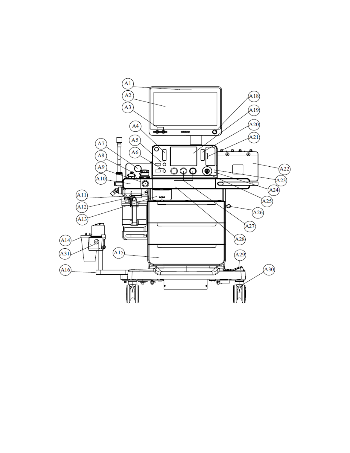
2.1.2 Appearance
2.1.2.1 Main Unit (Front View)
Front view of the A8 anesthesia machine.
2-3
Page 32
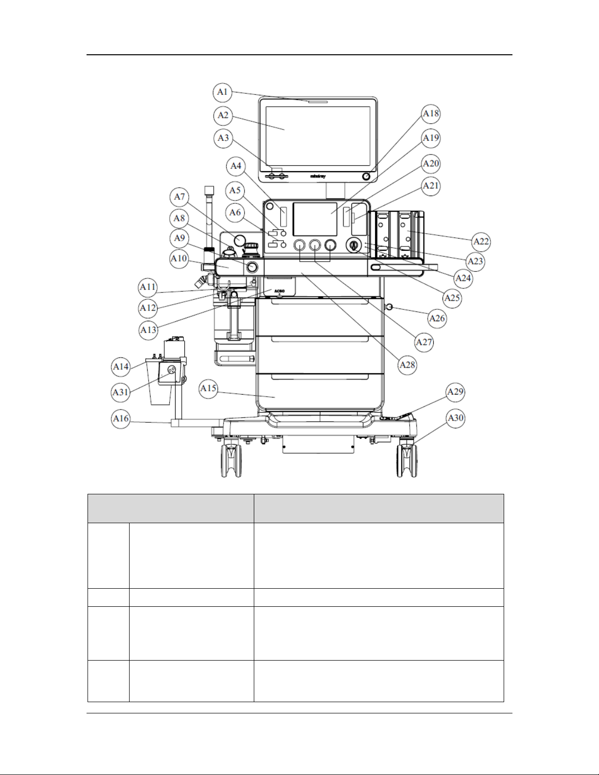
Front view of the A9 anesthesia machine.
Part Description
A1 Alarm lamp In case of an alarm, the alarm lamp is turned on in red,
yellow, or cyan, indicating different alarm priorities. Red
indicates a high priority, yellow indicates a middle
priority, and cyan indicates a low priority. If the alarm
lamp is off, no alarm is generated.
A2 Main display /
A3 Flow or O2 concentration
control knob of the
electronic flow control
system (EFCS)
A4 Auxiliary flowmeter
(O2/air) or high-flow O2
supply
You can rotate the knob to adjust the flow or O2
concentration.
There is a float in the flow tube. The scale corresponding
to the middle of the float is the current gas flow. The
flowmeter has a flow control knob to control the flow.
2-4
Page 33

r
r
r
Part Description
The gas flow increases when you rotate the knob
counterclockwise, and decreases when you rotate the
knob clockwise.
A5 Total flow control knob of
the auxiliary flowmete
A6 O2 concentration control
knob of the auxiliary
flowmete
A7 Negative pressure gauge The gauge is used to indicate the negative pressure.
A8 Negative pressure suction
switch
A9 O2 flush button The O2 flush button is used to supply oxygen at high
You can rotate the knob to adjust the total flow of the
auxiliary flowmeter.
You can rotate the knob to adjust the O2 concentration in
the total flow of the auxiliary flowmeter.
The switch is used to change the working mode of the
negative pressure suction device. It can be set to FULL,
OFF, or REG. FULL indicates that the negative pressure
suction device works continuously at maximum pressure,
and the regulating knob does not work. OFF indicates
that negative pressure is disabled and the negative
pressure suction device does not work. REG indicates
that you can rotate the negative pressure regulating knob
to adjust the pressure of the negative pressure suction
device. The negative pressure increases when you rotate
the negative pressure regulating knob counterclockwise,
and decreases when you rotate the negative pressure
regulating knob clockwise.
flow through the inspiratory limb of the breathing
system.
A10 O2 sensor door cover You can install the O2 sensor after opening the door
cover.
A11 Hook The hook is used to hold the breathing system.
A12 Negative pressure suction
tube fastene
A13 ACGO (standalone outlet
and switch)
A14 Negative pressure suction
liquid collection bottle
A15 Storage drawers Three (3) storage drawers that can be locked are
A16 Liquid collection bottle
and humidifier bracket
A18 Display control knob You can press the control knob to select a menu item or
The fastener is used to fasten the pipeline of the negative
pressure suction device.
The ACGO switch is used to enable/disable the ACGO
function. The ACGO standalone outlet is used to output
fresh gas.
The liquid collection bottle is used to collect effusions,
hematocele, pus, and other contaminants from the
patient.
provided.
The bracket is used to fasten the negative pressure
suction liquid collection bottle and humidifier.
confirm the settings. You can scroll the menu items or
change the settings by rotating the control knob
2-5
Page 34

Part Description
clockwise or counter clockwise.
A19 Status display A8: used to display the status of the gas supply pressure,
volume exchanger, electronic AGSS, and heating module
of the breathing system.
A9: used to display the status of the gas supply pressure,
volume exchanger, electronic AGSS, electronic
anesthetic vaporizer, and heating module of the breathing
system.
A20 Main flowmeter of the
backup flow control
system (BFCS)
A21 BFCS switch You can press the switch button to pen the BFCS control
A22 Vaporizer mounting
manifold
A23 Battery charge indicator The indicator is on when the battery is being charged.
A24 AC power status indicator The indicator is on when the system is connected to AC
A25 System switch The system switch is used to turn on or off the system.
A26 Key and lock The key and lock are used to lock the drawer.
A27 Pipeline supply pressure
gauge
The main flowmeter displays the total flow of the BFCS.
door. The flow regulating knob can be used to control the
air and O2 flow. The gas flow increases when you rotate
the knob counterclockwise, and decreases when you
rotate the knob clockwise.
A8: used to install two Selectatec vaporizers. The
mounting bar supports two vaporizers. There is an
interlock mechanism inside the vaporizers, so that only
one vaporizer is used to deliver one anesthetic agent at a
time.
A9: used to install and lock electronic vaporizers (two
electronic vaporizers can be installed).
power.
The gauge is used to indicate the pressure at the O2, air,
and N2O pipeline inlets.
A28 Volume exchanger door
cover
A29 Caster lock The caster lock is a brake used to lock/release all casters
A30 Caster The system is moved with the casters. The caster lock of
A31 Humidifier The humidifier must be connected to the pipeline when
You can open the volume exchanger door cover by
pulling the unlock button at the bottom right outward as
instructed.
when you step on it.
the machine is controlled by the central brake.
you enable high-flow O2 supply.
2-6
Page 35
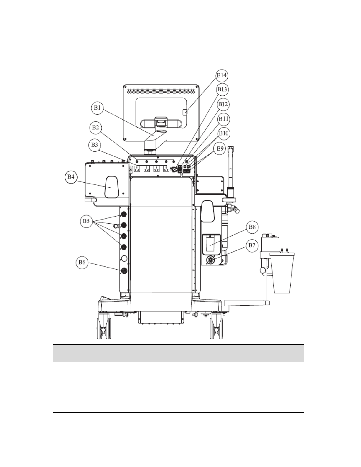
2.1.2.2 Main Unit (Rear View)
Part Description
B1 Display support arm The support arm is used to install the display.
B2 Fuse Each auxiliary power outlet is equipped with a fuse.
B3 Auxiliary AC power
outlet
B4 Cable hook The hook is used to suspend cables.
B5 Gas pipeline connector O2, air, and N2O pipeline connectors are provided.
Four auxiliary AC power outlets are provided.
2-7
Page 36

Part Description
r
B6 Vacuum pipeline
connecto
B7 Waste gas scavenging
connector
B8 Overfill protection Overfill protection of the negative pressure suction device is
B9 Network ports (CS1 and
CS2)
B10 SB ports (SB1, SB2, SB3,
and SB4)
B11 Equipotential lug The equipotential lug provides a grounding point. It
B12 Communication port
(SP1)
B13 Power inlet The power inlet is used to connect a supply mains cable.
The connector is used to connect to the vacuum source on
the hospital's wall.
The connector is used to connect to the waste gas disposal
system.
Use a waste gas disposal system that conforms to ISO
8835-3.
used to prevent overfill of waste liquid, so as to ensure
pipeline safety.
The network ports are used to connect to other devices
through network cables.
The SB ports are used to connect to USB devices.
Do not connect any devices to the SB ports of the machine,
except Mindray-approved USB devices and supported USB
mouses.
eliminates the potential difference between ground cables of
different devices to ensure safety.
An RS232 communication port is provided.
B14 VGA connector The VGA connector is used to connect to an external
display.
2-8
Page 37
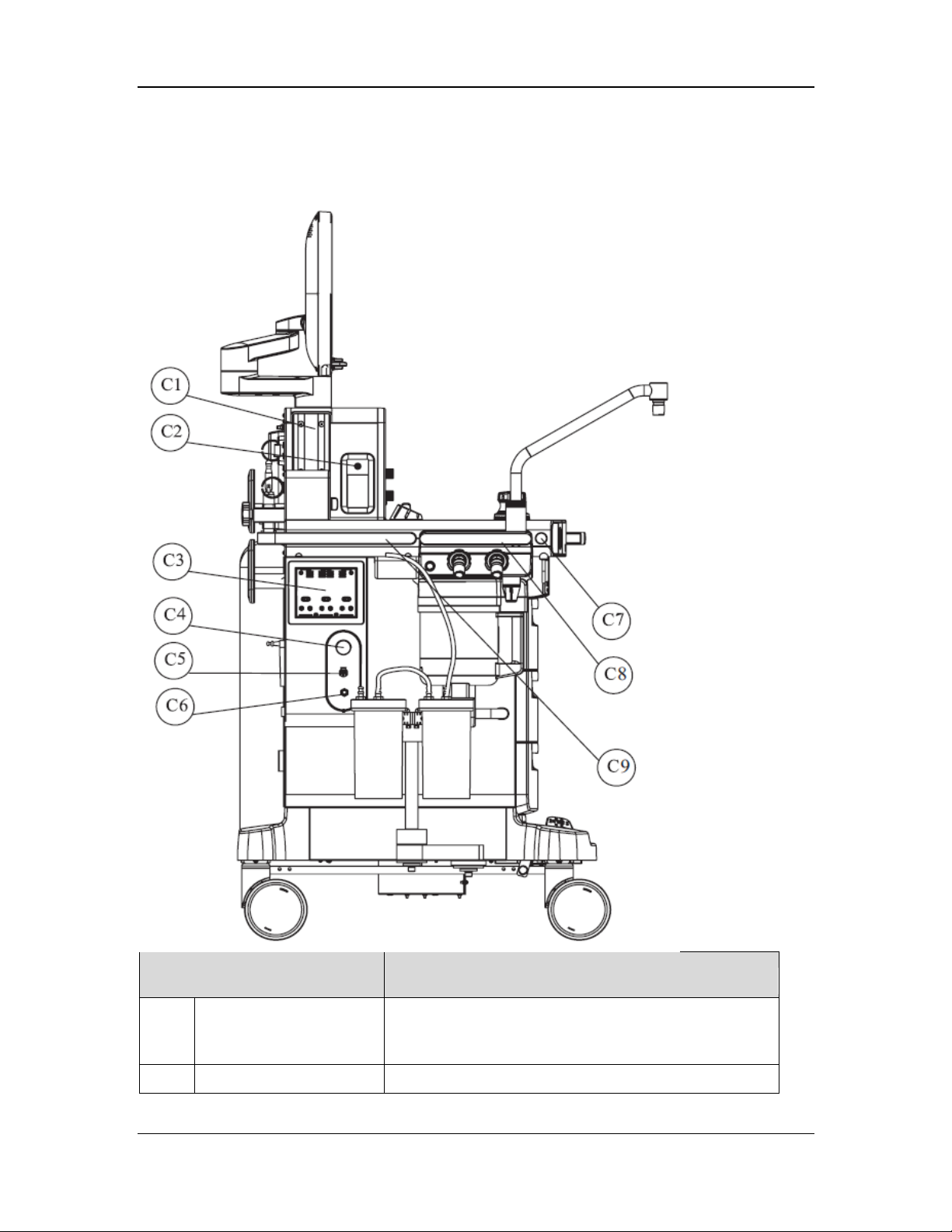
2.1.2.3 Main Unit (Left View)
Part Description
C1 Mounting rail The mounting rail is a standard accessory arm for
installing the monitor and other devices. Two mounting
rails are provided on the left and right of the machine.
C2 High-flow O2 outlet The outlet is used to output high-flow O2.
2-9
Page 38

Part Description
C3 Module slot FDA:
The module slot is used to install and identify the AG
module described in this manual.
Canada:
The module slot is used to install and identify the NMT,
AG, and BIS module described in this manual.
C4 Electronic AGSS flow
regulating knob
C5 Sample gas return port A sample gas return port is provided for the gas module.
C6 Auxiliary high-pressure
O2 outlet
C7 O2 sensor door cover
switch
C8 Handle The handle can bear maximum force of 10 kgf (22 lbf).
C9 Handle The handle is used for pushing/pulling/turning the
You can rotate the knob clockwise or counterclockwise
to adjust the flow in the AGSS, until the float on the
status display is between the Min and Max scales.
The outlet is used to connect to an external device, for
example, a jet ventilator.
The switch is used to open the O2 sensor door cover.
The handle is only used for disassembling the breathing
system, but not for pushing/pulling/lifting the anesthesia
machine.
anesthesia machine. It can bear maximum force of 80 kgf
(176 lbf).
2-10
Page 39
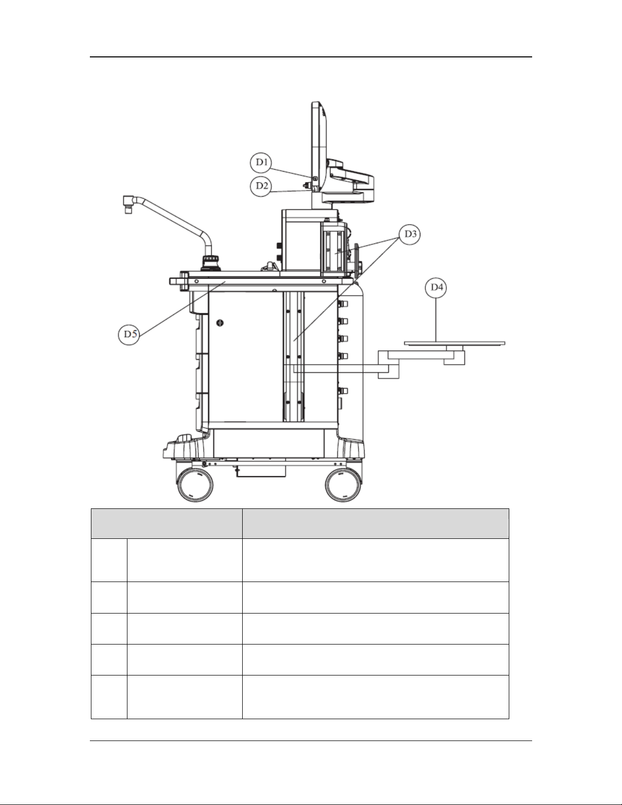
2.1.2.4 Main Unit (Right View)
Part Description
D1 Work lamp switch The switch is used to turn on/off the work lamp. Three
settings are provided: Off, Low, and High. You can turn on
the work lamp only when the system switch is turned on.
D2 Work lamp The work lamp is located under the display to illuminate
the work surface.
D3 Mounting rail The mounting rail is a standard accessory arm for installing
the monitor and other devices.
D4 Collapsible work
surface
D5 Handle The handle is used for pushing/pulling/turning the
The collapsible work surface can be rotated horizontally
for 180 degrees. It bears maximum load of 14 kg (31 lbs).
anesthesia machine. It can bear maximum force of 80 kgf
(176 lbf).
2-11
Page 40
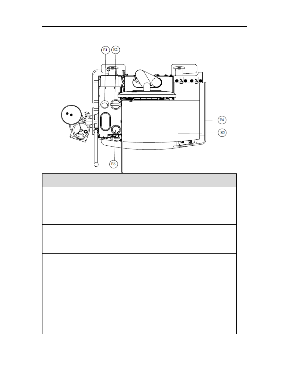
2.1.2.5 Main Unit (Top View)
f
Part Description
E1 Airway pressure gauge 1 The gauge is used to indicate the patient's airway
pressure.
A slight difference between the readings of the airway
pressure gauge and the electronic readings is normal.
Contact the after-sales service department of Mindray if
the difference exceeds 15%
E2 Manual/auto switch The manual/auto switch is used to switch between
mechanical ventilation and manual ventilation.
E4 Handrail The handrail is an encircling metal bar used for moving
the machine.
E5 Work surface The stainless steel work surface bears maximum force
of 30 kg
E6 APL valve 1 The APL valve is a rotary regulator for setting the
pressure limit of the breathing system during manual
ventilation. The scales on the APL valve indicate
approximate pressure. The APL valve is set to the SP
position during spontaneous breathing. If necessary, lift
the APL valve to release pressure quickly. At the flow
of 3 L/min, the pressure of the APL valve under a dry
or wet condition must be greater than 1 cmH2O and
less than 3 cmH2O. At the flow of 30 L/min, the
pressure of the APL valve under a dry or wet condition
must be greater than 1 cmH2O and less than 5 cmH2O.
(66 lbf).
2-12
Page 41
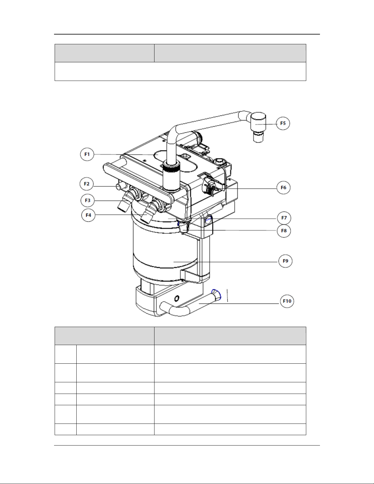
b
Part Description
Values on the APL valve and airway pressure gauge are for reference only. The calibrated
patient's airway pressure is displayed on the user interface.
2.1.2.6 Breathing System
Part Description
F1 Breathing check valve
inspection window
F2 Leak test plug The leak test plug is used to connect the breathing tube
F3 Expiration connector The breathing circuit has an expiration connector.
F4 Inspiration connector The breathing circuit has an inspiration connector.
F5 Bag arm The bag arm is used to connect the manual ventilation
F6 O2 sensor The O2 sensor is used to monitor the O2 concentration.
You can inspect the status of the inspiratory and
expiratory check valves from outside the machine.
for the leak test.
ag.
2-13
Page 42
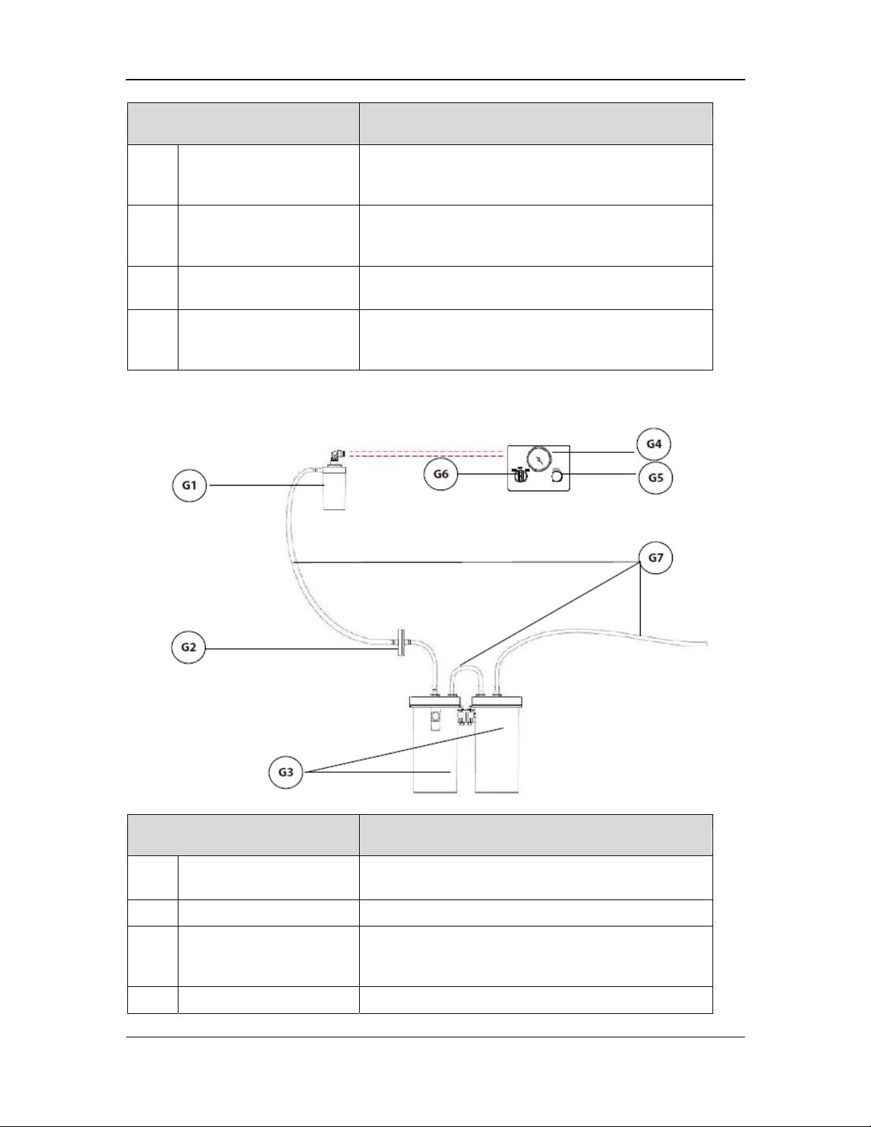
Part Description
F7 Absorber bypass assembly The absorber bypass assembly is used to retain the
pressure in the breathing circuit when you replace the
sodalime in the CO2 absorber canister.
F8 Water collection cup The water collection cup is used to collect condensate
from the breathing system. It must be periodically
removed and emptied.
F9 CO2 absorber canister The CO2 absorber canister is a container for holding
the CO2 absorbent (bulk or Pre-pak CO2 absorbent).
F10 Canister lock The canister lock is a lever locking mechanism for
locking (in the horizontal position)/unlocking (in the
vertical position) the canister.
2.1.2.7 Negative Pressure Suction Device
Part Description
G1 Overfill protection Overfill protection is used to prevent overfill of waste
liquid, so as to ensure pipeline safety.
G2 Filter The filter is used to filter out moisture and impurities.
G3 Liquid collection bottle The liquid collection bottle is used to collect effusions,
hematocele, pus, and other contaminants from the
patient.
G4 Negative pressure gauge The gauge is used to indicate the negative pressure.
2-14
Page 43
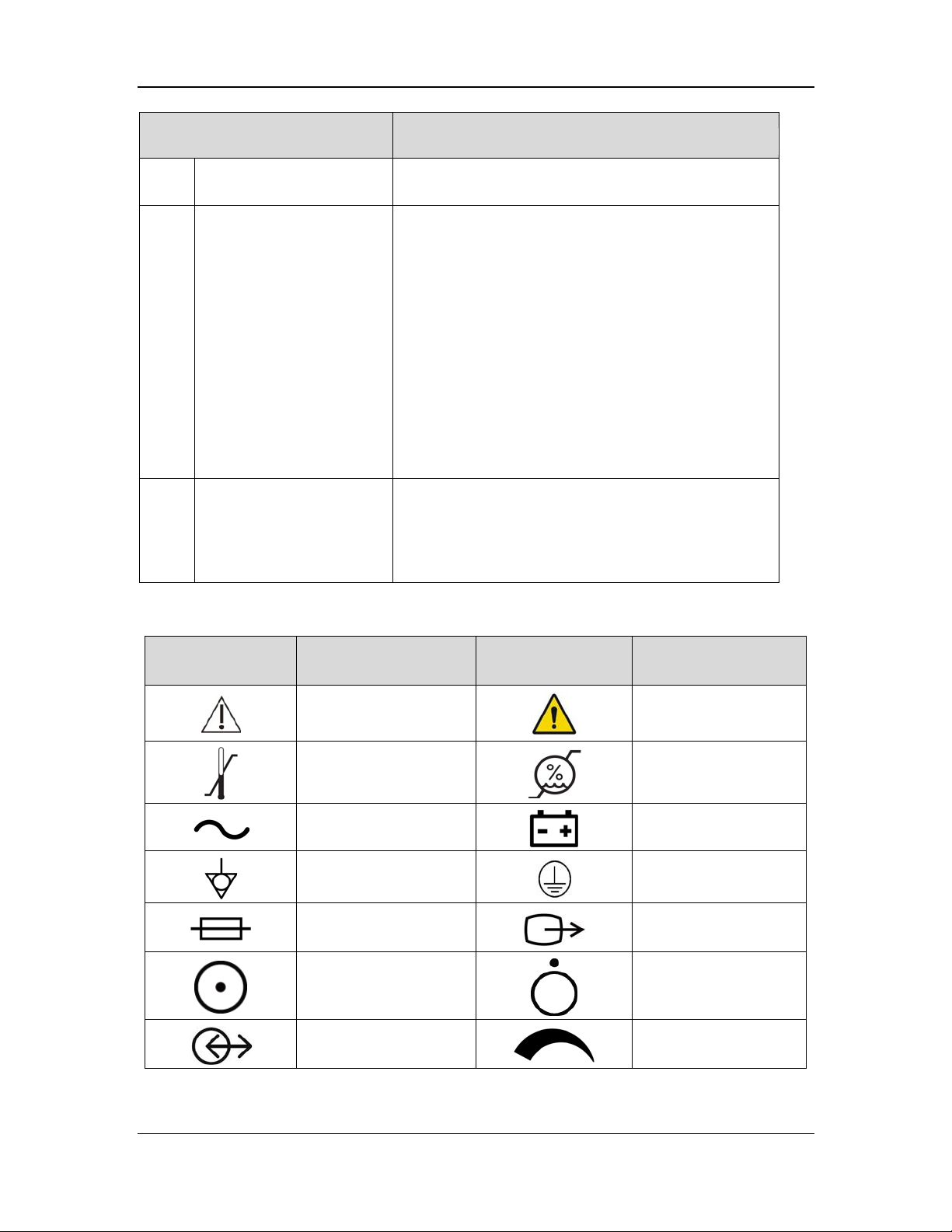
Part Description
p
G5 Negative pressure
regulating knob
G6 Selection switch The switch is used to change the working mode of the
G7 Suction tube The suction tube is used to deliver effusions,
The knob is used to adjust the pressure of the negative
pressure suction device.
negative pressure suction device. It can be set to FULL,
OFF, or REG. FULL indicates that the negative
pressure suction device works continuously at
maximum pressure, and the regulating knob does not
work. OFF indicates that negative pressure is disabled
and the negative pressure suction device does not work.
REG indicates that you can rotate the negative pressure
regulating knob to adjust the pressure of the negative
pressure suction device. The negative pressure
increases when you rotate the negative pressure
regulating knob counterclockwise, and decreases when
you rotate the negative pressure regulating knob
clockwise.
hematocele, pus, and other contaminants out of the
patient. The inner diameter of the suction tube is Φ8
(5/16"). The suction tube is directly inserted in the
connector.
2.1.3 Labels
Symbol Description Symbol Description
CAUTION!
Environment: temperature
range
Electricity: alternating
current (AC)
Electricity: equipotential
illar
Electricity: fuse or circuit
breaker
Electricity: powered on
Electricity: input/output
WARNING
Environment: humidity
range
Electricity: internal
battery
Electricity: protective
ground
VGA connector
Electricity: powered off
Gas flow: flow control
knob
2-15
Page 44
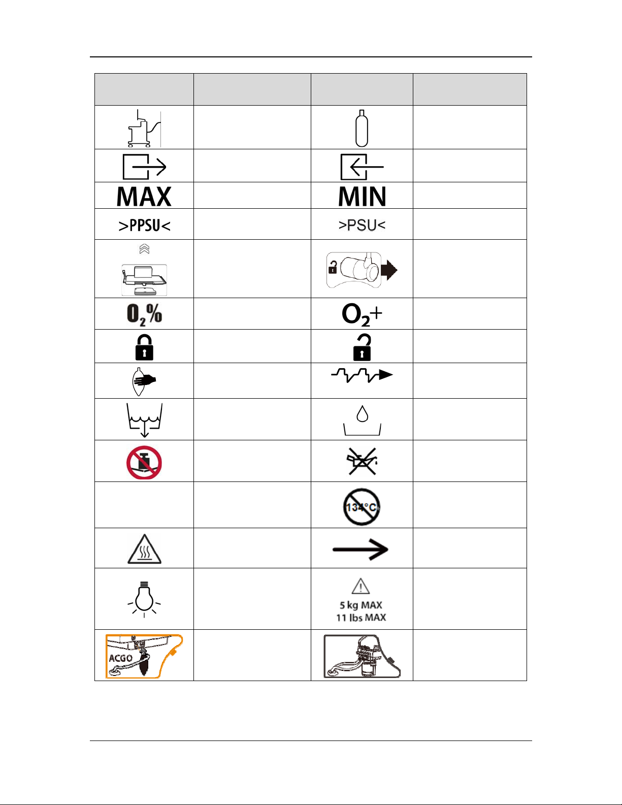
p
N
p
N
p
Symbol Description Symbol Description
Pipeline gas
Gas outlet
Maximum value
Material:
olyphenylsulfone
Remove the volume
exchanger
O2 sensor connector
Lock/Unlock: lock
Manual ventilation
Drainage
Gas cylinder
Gas inlet
Minimum value
Material: polysulfone
Remove the O2 sensor
Gas: O2 flush button
Lock/Unlock: unlock
Mechanical ventilation
Water trap
134°C
o weight: Do not press
against it.
Resistance to high
temperature/high
ressure/disinfection
Caution: heat
Electricity: light
ACGO mode
2-16
Do not add fuel.
o resistance to high
temperature/high
ressure/disinfection
Direction
Bearing capacity
Mechanical ventilation
mode
Page 45

N
N
m
r
p
p
p
p
Symbol Description Symbol Description
IPX14
Connect the filter
Absorber canister on
egative pressure suction
device
Degree of protection
against harmful ingress of
water for the anesthesia
machine equipped with the
odule
BIS
Identifier: manufacturer
reference number/catalog
numbe
CF-type defibrillator-proof
applied part
The battery is full. The AC
connected to power the
system.
ower supply has been
IPX4
APL valve
Absorber canister off
egative pressure gas
supply
Degree of protection
against harmful ingress of
water for the BIS module
Identifier: serial number
BF-type
defibrillator-proof applied
art
Alarm Audio Off icon
The battery is not full. The
AC power supply has been
connected to charge the
battery and power the
system.
The battery is full and is
owering the system. The
AC power supply is
disconnected.
The battery is not full and
is powering the system.
The AC power supply is
disconnected.
The battery is low and is
owering the system. You
are advised to charge the
battery. The AC power
supply is disconnected.
Alarm Audio Pause icon
Alarm Off icon
Low-priority information
Middle-priority
information
2-17
Page 46
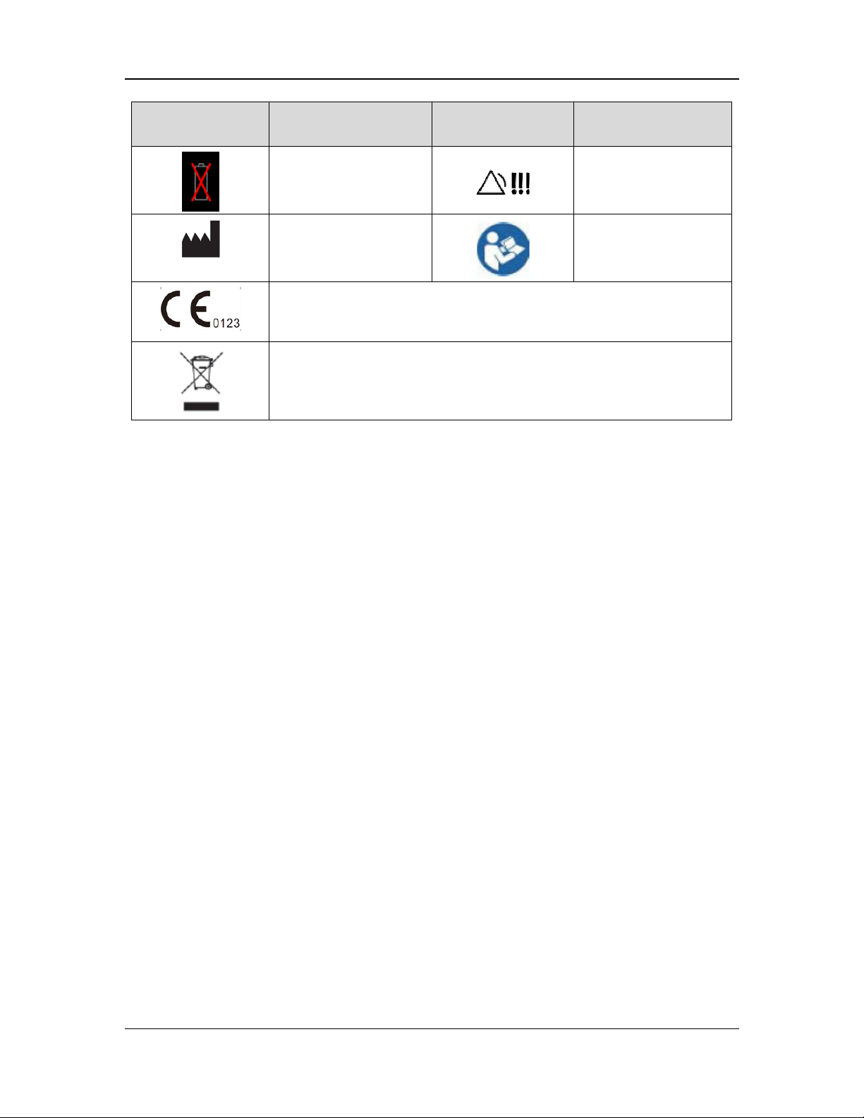
N
Symbol Description Symbol Description
o battery
Identifier: manufacturer
The product complies with EU Medical Devices Directive (93/42/EEC) and
meets the basic requirements in Annex I of the directive, so it has the CE
mark.
Electrical:
WEEE (Waste of Electrical and Electronic Equipment) Marking. Separate
treatment from general waste at end of life.
High-priority information
Refer to instruction
manual/booklet
2-18
Page 47

2.1.4 Acronyms and Abbreviations
Acronym or Abbreviation Description
AA Anesthetic agent
ACGO Auxiliary common gas outlet
AGSS Anesthesia gas scavenging system
Alpha Power of the Alpha waveband/Total power
AMV Adaptive minute ventilation
APL Airway pressure limit
Apnea I:E Apnea inspiratory time:expiratory time ratio
APRV Airway pressure release ventilation
BC Burst count
Beta Power of the Beta waveband/Total power
BIS Bispectral index
BSR Burst suppression rate
BTPS Body temperature and pressure, saturated gas
C Dynamic compliance
CPAP/PS Continuous positive airway pressure/pressure support ventilation
CPB Cardiopulmonary bypass
DBS Double burst stimulation
Delta Power of the Delta waveband/Total power
EMG Muscle activity and high frequency artifacts
ESI EEG anesthesia depth index
Exp% Inspiratory termination level
FiO2 Fraction of inspired oxygen
Flow Flow
F-Trig Flow trigger level
IBW Ideal body weight
I:E Inspiratory time:Expiratory time ratio
MEAN Mean pressure
MF Median frequency
Min RR Minimum respiratory rate
MV Minute volume
MV% Minute volume in percentage
2-19
Page 48

Acronym or Abbreviation Description
MVi Inspiratory minute volume
MVleak Leakage minute volume
N2O Nitrous oxide
NMT Neuromuscular transmission
O2 Oxygen
Pinsp Pressure control level of inspiration
Plimit Pressure limit level
PAW Airway pressure
PCV Pressure control ventilation
PCV-VG Pressure control ventilation with volume guarantee
PEAK Peak pressure
PEEP Positive end-expiratory pressure
PLAT Plateau pressure
PPF Peak power frequency
ΔPapnea Pressure of apnea ventilation
ΔPsupp Pressure support level
PTC Post tetanic counting
P-Trig Pressure trigger level
R Airway resistance
RR Respiratory rate
SEF Spectral edge frequency
SIMV-PC Synchronized intermittent mandatory ventilation - pressure control
SIMV-VC Synchronized intermittent mandatory ventilation - volume control
SIMV-VG Synchronized intermittent mandatory ventilation - volume
guarantee
SP Spontaneous breathing
SQI Signal quality index
ST Single twitch stimulation
T1 First stimulus response value
T1% Ratio of T1 to the reference value
Theta Power of the Theta waveband/Total power
Tinsp Inspiratory time
TOF Train-of-four
2-20
Page 49
Acronym or Abbreviation Description
TP Total power
Tpause Percentage of inspiratory pause time
Tslope Time for the pressure to rise to target pressure
Trig Window Trigger window
VCV Volume control ventilation
Vt Tidal volume
Vti Inspiratory tidal volume
2-21
Page 50
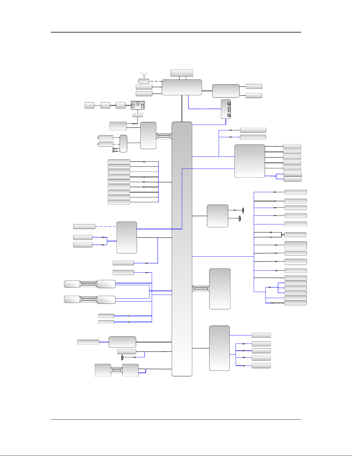
2.2 Subsystems
2.2.1 Electrical Circuit
C43C44
P7
4*P64*P5
C7
P44
P9
B6
P9
P15
P15
P15
P16
P16
P16
B13
B13
B13
C22
M1
M1
B14*2
P17*2
P18*2/*1
对插
按钮
对插
按钮
J1
J1
B22
B22
C23
J1
B15
/B16
J7
B8
B21
J3
J2
J3
J2
C8
C9
C5
P8*2
C6
C21
J9
J4
C15
wifi天线
P2
B2
P1
J1
J3
P3
C1 C2
J8
C3
B5
J5
按钮
对插
C20
C24
C34
C35
J7J15
J9
J5
B1
J2
C10
J5
J2
J8 &
J12
J7
B18
J17
J16 & J18
J11
J10
C4
J4
J4
C11
C12
J9
J6
C13
C16
C25
J1
对插
按钮
J3
J7
B17
B20
C27
J2&J3
B3
J1
B7
J7
C14
C15
C26
J1
J2
J10
J12
J1
C5
P19*4
P20
P4*2
B4
P10*2
B8
B9
J7&J8
J4&J5
J13
J11
J14
C18
C32
C33
C28
C31
C29
C30
P11*2
P12
B10
P13
P14*2
B11
B12
B19
P21
P22
P23
P24
P25
P26
P27
P28
P29
P30
P31
P32
P33
P34
P35
C17
J3
C19
M2
P36
C41
P37 B23
P38*2
硬连接
按钮
M4
M3
C38
B24
C36
J2J1
C37
C39
J4
J7
J14
J15
C40
J13
J3
J8
J1
B25
C42
J7
P39*3
P40*2
P41
P42
P43*2
2-22
Page 51

b
b
r
b
/ /
r
Electrical circuit diagram
Parts List
B1 CPU board B2 Alarm lamp board
B3 Key lighting board B4 Host encoder board
B5 DC-DC power board B6 Battery adapter board
B7 External I/O interface board B8 Backlight board
B9 Small-display CPU board B10 Auxiliary O2/air keyboard
B11 BFCS switch control board B12 Power indicator board
B13 Gas inlet sensor board B14 High-flow sensor board
B15
B17
B19 APL indicator board B20 Monitoring board
B21 EFCS outlet pressure sensor board B22
B23 AGSS sensor board B24 Module rack backplane
B25 EFCS flowmeter monitoring board
P1 Speaker P2 Wi-Fi module
P3 Display assembly P4 Electronic flowmeter encoder
P5 Auxiliary outlet P6 One-way circuit breaker
P7 Main circuit breaker P8 Fuse
P9 Lead-acid battery P10 System position switch
P11 Electromagnet P12 8.4-inch display
P13 Segment display P14 Auxiliary flowmeter encoder
P15 Gas inlet pressure switch P16 Cylinder pressure sensor
P17 Proportional valve P18 Three-way valve
P19 Zeroing three-way valve P20
P21 O2 cell P22 Circuit switch
P23 Sodalime canister switch P24 ACGO switch
P25 Heater P26 O2 cell calibration valve
P27 Auto/manual valve P28
P29 Manual/auto switch and line P30 PEEP switch
P31 Safety valve P32 Inspiratory proportional valve
P33 PEEP proportional valve P34 Ventilator flow sensor
P35 VR switch P36
P37 AGSS pilot valve and line P38 AG switch three-way valve
P39 Flow sensor P40 Proportional valve
P41 NC two-way valve P42 NO two-way valve
P43 Three-way valve P44 AC-DC power board
C1
C3
C5 AC inlet and line C6 AC input line
Auxiliary flowmeter monitoring
oard
Sensor adapter board (with
transpulmonary pressure)
Sensor adapter board (without
anspulmonary pressure)
t
Connection line between the display
and the CPU board
Connection line between the alarm
lamp board and the CPU board
B16
B18 Motherboard
C2
C4
High-flow O2 therapy monitoring
oard
Electronic vaporizer base interface
oard
Intrapulmonary pressure zeroing
three-way valve and line
Auto/manual valve position switch
and line
Pneumatic lock switch and line of the
vaporize
Connection line between the
touchscreen and the CPU board
Connection line between the main
encoder board and the CPU board
2-23
Page 52

b
b
b
/ /
C7 AC input interconnection line C8 AC-to-DC line
C9
C11 HDMI network cable C12
C13
C15 Backlight board connection line C16
C17 IVO display connection line C18
C19
C21
C23
C25
C27 Pneumatic assembly connection line C28 APL indicator connection line
C29 Circuit switch line C30 Sodalime canister switch line
C31 O2 cell connection line C32
C33 VR switch connection line C34 Electronic vaporizer power line
C35
C37
C39
C42 Electronic flowmeter valve line C43 Auxiliary output connection line
C44 Auxiliary outlet line
M1 Electronic vaporizer M2 Vaporizer base valve assembly
M3 Internal AG module M4 Module rack
Connection line between the battery
adapter board and the DC-DC board
Connection line between the
motherboard and the small-display
CPU board
Connection line between the auxiliary
O2/air assembly and the small-display
CPU board
Connection line of the O2 pressure
switch at the gas inlet
Connection line of the auxiliary
O2/air valve
High-flow valve connection line
Connection line between the
motherboard and the sensor adapter
oard
Electronic vaporizer communication
line
Connection line between the
motherboard and the internal AG
module
Connection line between the
motherboard and the module rack
C10
C14 System switch line
C20
C22 High-flow sensor connection line
C24
C26
C36
C38
C41 Electronic flowmeter sensor line
Connection line between the CPU
oard and motherboard
Connection line between the
motherboard and the I/O interface
oard
Connection line between the auxiliary
O2/air assembly and the small-display
CPU board
Connection line of the auxiliary O2/air
keyboard
Connection line between the
motherboard and the gas supply
pressure monitoring board
Connection line between the
motherboard and the auxiliary O2/air
assembly
Connection line of the zeroing
three-way valve
Connection line of the expiratory
valve assembly
Connection line between the
motherboard and the AGSS
Three-way valve line of the internal
AG module
2-24
Page 53
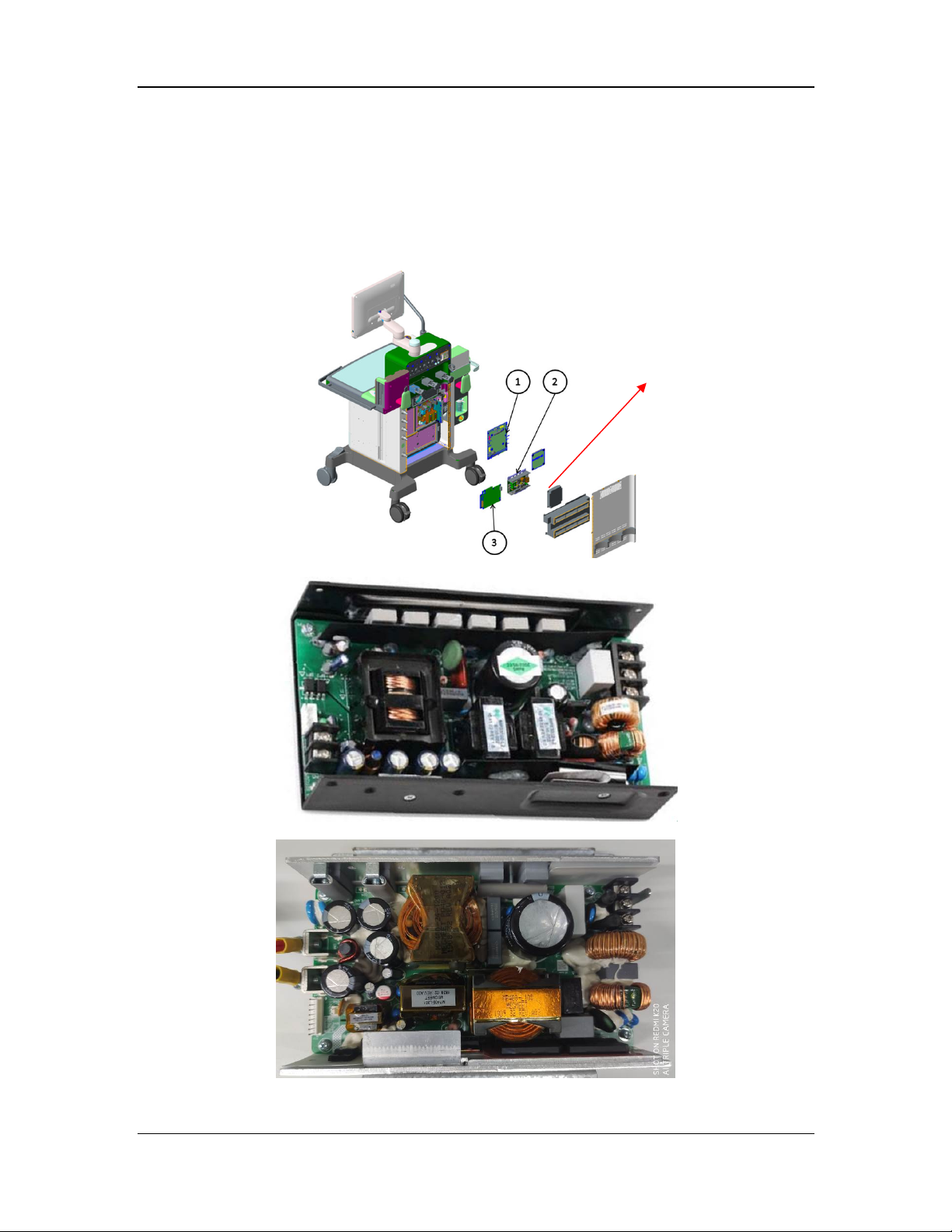
2.2.2 Power System
2.2.2.1 AC-DC Board
The AC-DC board converts AC power into DC power to power the anesthesia machine. The
AC-DC board of the A8 provides 19 V output, and that of the A9 provides 24 V output. The two
AC-DC boards have different part numbers and are not interchangeable. Pay attention to the part
numbers during servicing.
AC-DC board
Installation position of the AC-DC board
AC-DC board (19 V output)
AC-DC board (24 V output)
2-25
Page 54
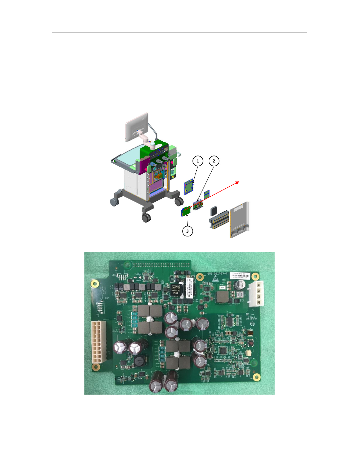
2.2.2.2 DC-DC Board
Under control of the system switch, the DC-DC board converts the DC power outputted by the
AC-DC board or the lead-acid battery power into the DC power required by the system to
produce 5 V, 12 V, or 24 V, and manages charging of the lead-acid battery.
This board is configured with power board software. In addition, the power boards of the A8 and
A9 basically have the same appearance, as shown in the figure below. Pay attention to the part
numbers during servicing.
DC-DC board
Installation position of the DC-DC board
DC-DC board (A9)
2-26
Page 55
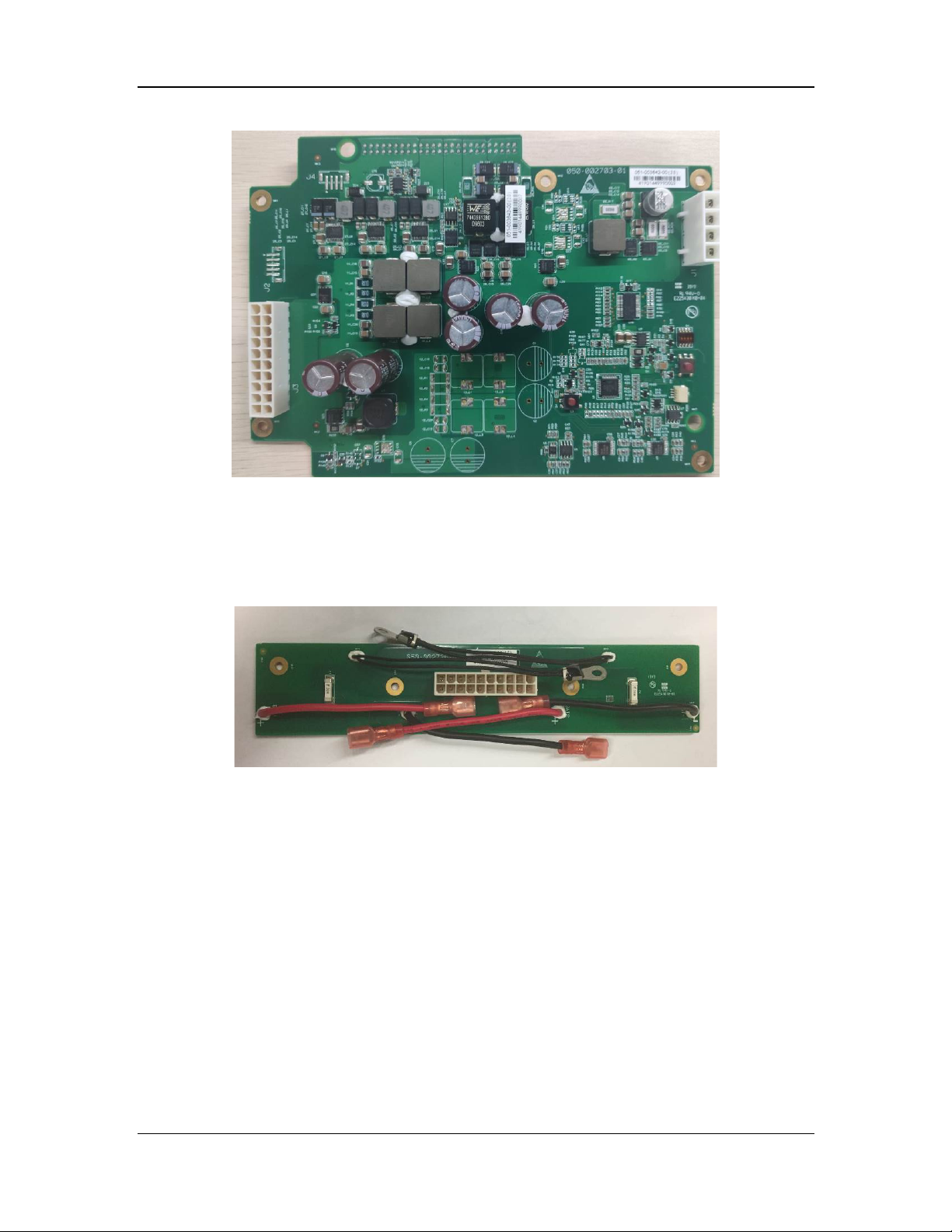
DC-DC board (A8)
2.2.2.3 Battery Adapter Board
Two types of battery adapter boards are available: dual-battery adapter board and single-battery
adapter board. The battery adapter board is an optional part installed inside the battery box. The
battery adapter board transfers battery signals to the motherboard and provides the following
functions: battery in-position detection, temperature detection, and current protection.
Dual-battery adapter board
2.2.2.4 Auxiliary Output
Auxiliary outputs supply power for other devices or instruments. The voltage ranges and
frequencies of the power supplies should be the same as those of the input mains supply for the
anesthesia machine. The auxiliary output system has four auxiliary outputs, each with a circuit
breaker.
2-27
Page 56
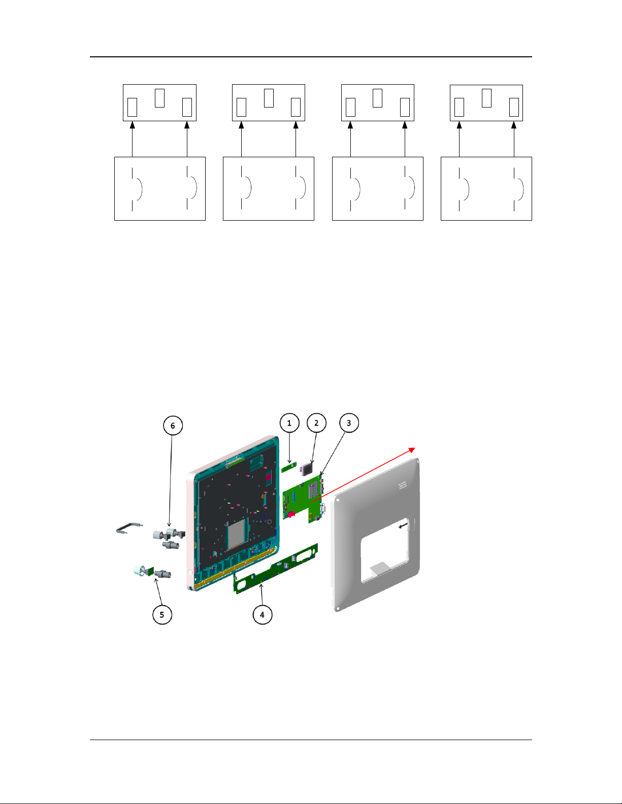
Auxiliary Outlet 1
Auxiliary Outlet 2
Auxiliary Outlet 3 Auxiliary Outlet 4
Breaker 4Breaker 3Breaker 2Breaker 1
2.2.2.5 Others
The anesthesia machine also contains the heating module, lead-acid battery, and other parts. The
heating module is driven by the power board and provides dual overheating protection by means
of software and hardware. The lead-acid battery ensures that the anesthesia machine can operate
properly when the mains supply is unavailable or abnormal.
2.2.3 Display System
2.2.3.1 Large-Display CPU Board
The CPU board implements GUI man-machine interaction; provides power management for the
VPM, VCM, electronic flowmeter, electronic vaporizer, auxiliary O2/air board, and small-display
CPU board; and protects parameter modules. It mainly consists of the CPU core system and
peripheral interface circuits.
This board is configured with large-display control software.
Large-display
CPU board
Installation position of the large-display CPU board
2-28
Page 57
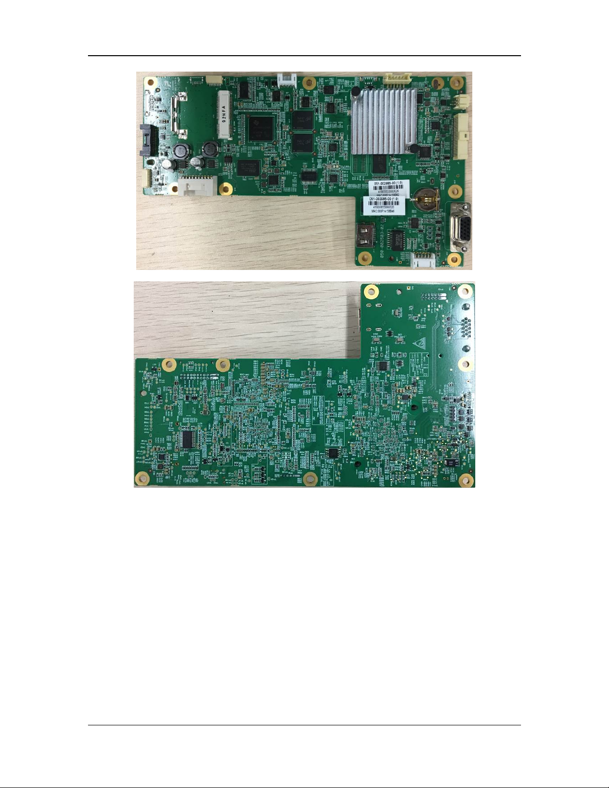
Large-display CPU board (top view)
Large-display CPU board (bottom view)
2.2.3.2 Display and Touchscreen
An 18.5-inch 1920×1080 full laminated display assembly is used, consisting of a display and a
touchscreen. It acts as the main input/output part for man-machine interaction.
2.2.3.3 Key Lighting Board
The key lighting board is installed at the bottom of the display assembly for the lighting of the
work surface. It provides a key to switch between the three light settings: high brightness, low
brightness, and off. In addition, the key lighting board is connected to the main encoder board
and the flowmeter encoder to identify the encoder, and communicates with the host computer
(CPU board) through the serial port. This board is configured with software.
2-29
Page 58
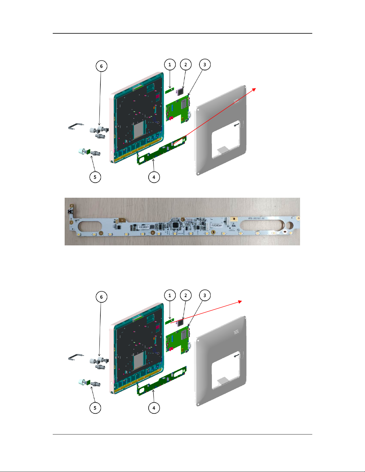
Key lighting board
Installation position of the large-display CPU board
Key lighting board
2.2.3.4 Alarm Lamp Board
The alarm lamp board is mainly used to display the alarm status of the machine by blinking in red,
yellow, or blue.
Alarm lamp board
Installation position of the alarm lamp board
2-30
Page 59
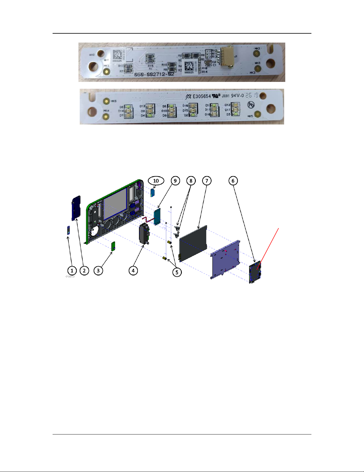
Alarm lamp board (top view)
Alarm lamp board (bottom view)
2.2.3.5 Small-Display CPU Board
The small-display CPU board is mainly used to drive small-screen display and transfer auxiliary
O2/air signals. This board is configured with small-display control software.
Small-display
CPU board
Installation position of the small-display CPU board
2-31
Page 60
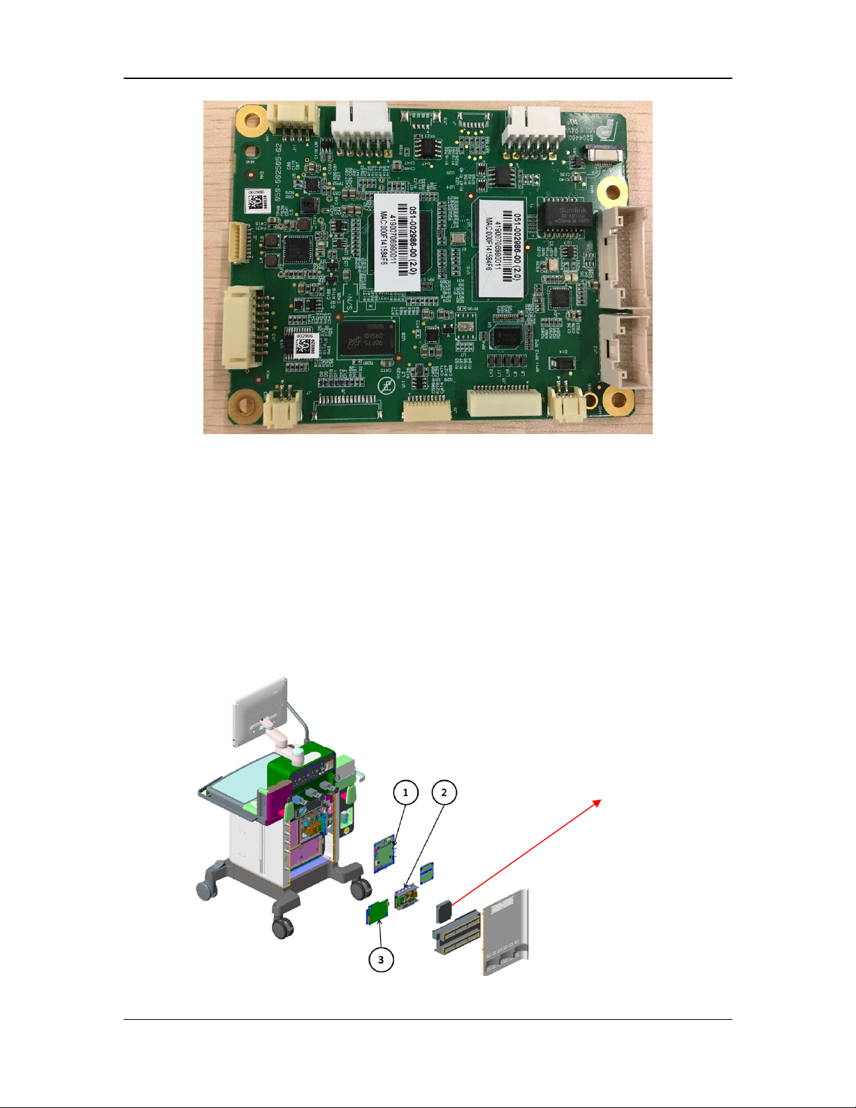
Small-display CPU board
2.2.3.6 Small Display
An 8.4-inch 800×600 display with an LVDS connector is used to display the dynamic graph of
ventilation, gas supply pressure, and vaporizer working status.
2.2.4 Monitoring System
2.2.4.1 Monitoring Board
The monitoring board detects the pressure and flow of the anesthesia ventilator and anesthesia
breathing system, controls valves, monitors and collects the status, reads the O2 concentration,
reads the switch status, monitors the pressure and flow in the circuit, and accurately controls the
tidal volume.
The monitoring board is buckled to the motherboard. The monitoring board consists of the VCM
and VPM, and is configured with the VCM and VPM function software.
Monitoring board
Installation position of the monitoring board
2-32
Page 61
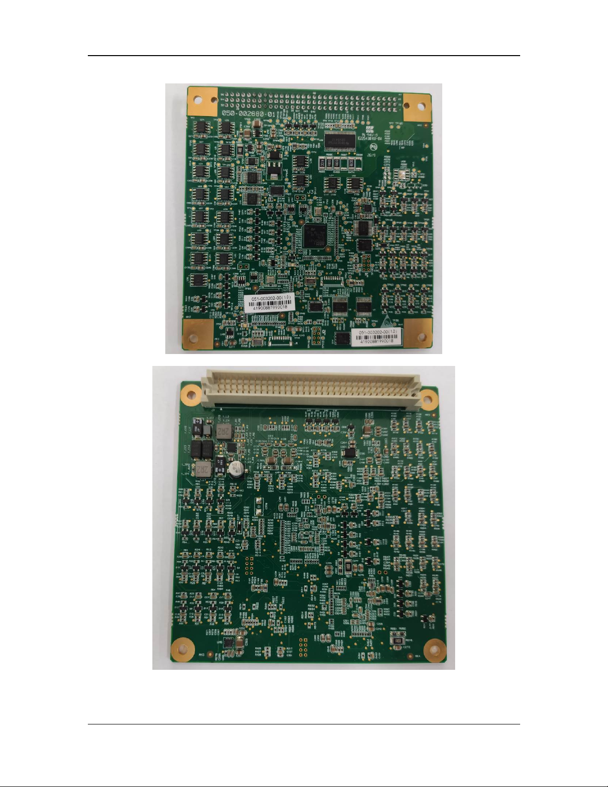
Monitoring board (top view)
Monitoring board (bottom view)
2-33
Page 62
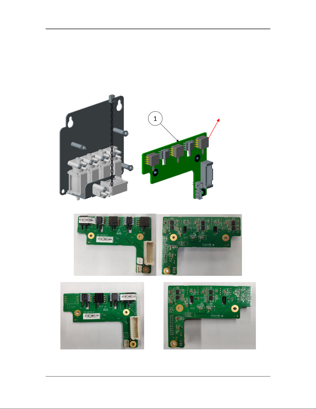
2.2.4.2 Sensor Adapter Board
Two types of sensor adapter boards are available: one with intrapulmonary pressure (Canada only)
and the other without intrapulmonary pressure.
The sensor adapter board is mainly used to process inspiratory and expiratory differential
pressure sensor signals, PEEP sensor signals, PAW pressure sensor signals, intrapulmonary
pressure sensor signals, and adapter three-way valve control signals.
Sensor adapter board
Installation position of the sensor adapter board
Sensor adapter board (with intrapulmonary pressure, Canada only)
Sensor adapter board (without intrapulmonary pressure)
2-34
Page 63
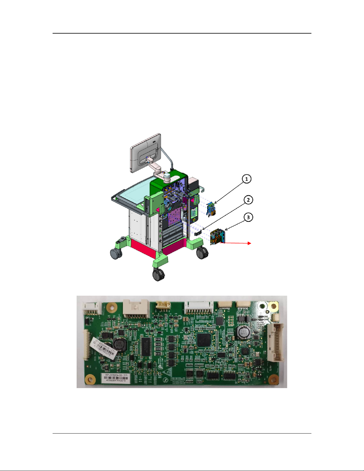
g
2.2.5 EFCS Flowmeter System
2.2.5.1 EFCS Flowmeter Monitoring Board
The EFCS flowmeter monitoring board is the core control part of the EFCS flowmeter of the
anesthesia machine. The EFCS flowmeter monitoring board controls the O2/N2O/air flow
through the proportional valve, and monitors and feeds back the O2/N2O/air flow through the
flow sensor. In addition, the total flow monitored by the O2 flow sensor is processed by the
EFCS flowmeter monitoring board. Moreover, the EFCS flowmeter monitoring board drives the
three-way valve, switch valve, and electromagnet, so as to switch to the mechanical BFCS when
the proportional valve, flow sensor, or other electrical components fail. This board is configured
with EFCS flowmeter software.
EFCS flowmeter
monitorin
Installation position of the EFCS flowmeter monitoring board
EFCS flowmeter monitoring board (top view)
board
2-35
Page 64
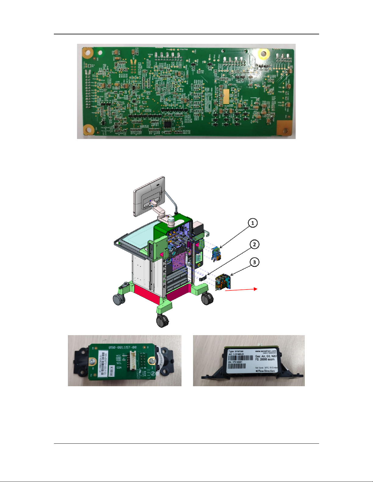
EFCS flowmeter monitoring board (bottom view)
2.2.5.2 Flow Sensor Board
The flow sensor board is mainly used to monitor the O2/N2O/air flow and feed back the detected
signals to the EFCS flowmeter monitoring board through the I2C bus.
Flow sensor board
Installation position of the flow sensor board
Flow sensor board (top view) Flow sensor board (side view)
2.2.5.3 BFCS Switch Board
The BFCS switch board is mainly used to monitor the open/closed status of the BFCS door. Two
Hall switches are used to feed back the status signals of the BFCS door to the EFCS flowmeter
monitoring board.
2-36
Page 65
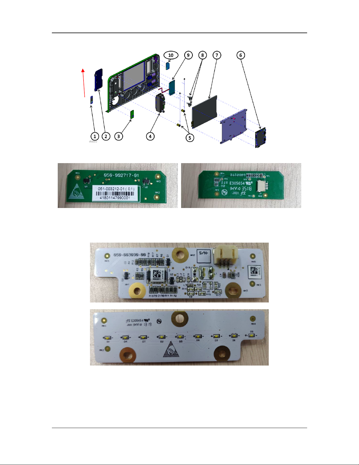
BFCS switch board
Installation position of the small-display CPU board
BFCS switch board
2.2.5.4 BFCS Backlight Board
The BFCS backlight board is mainly used to provide lighting for the backup flowmeter.
BFCS backlight board (top view)
BFCS backlight board (bottom view)
2-37
Page 66
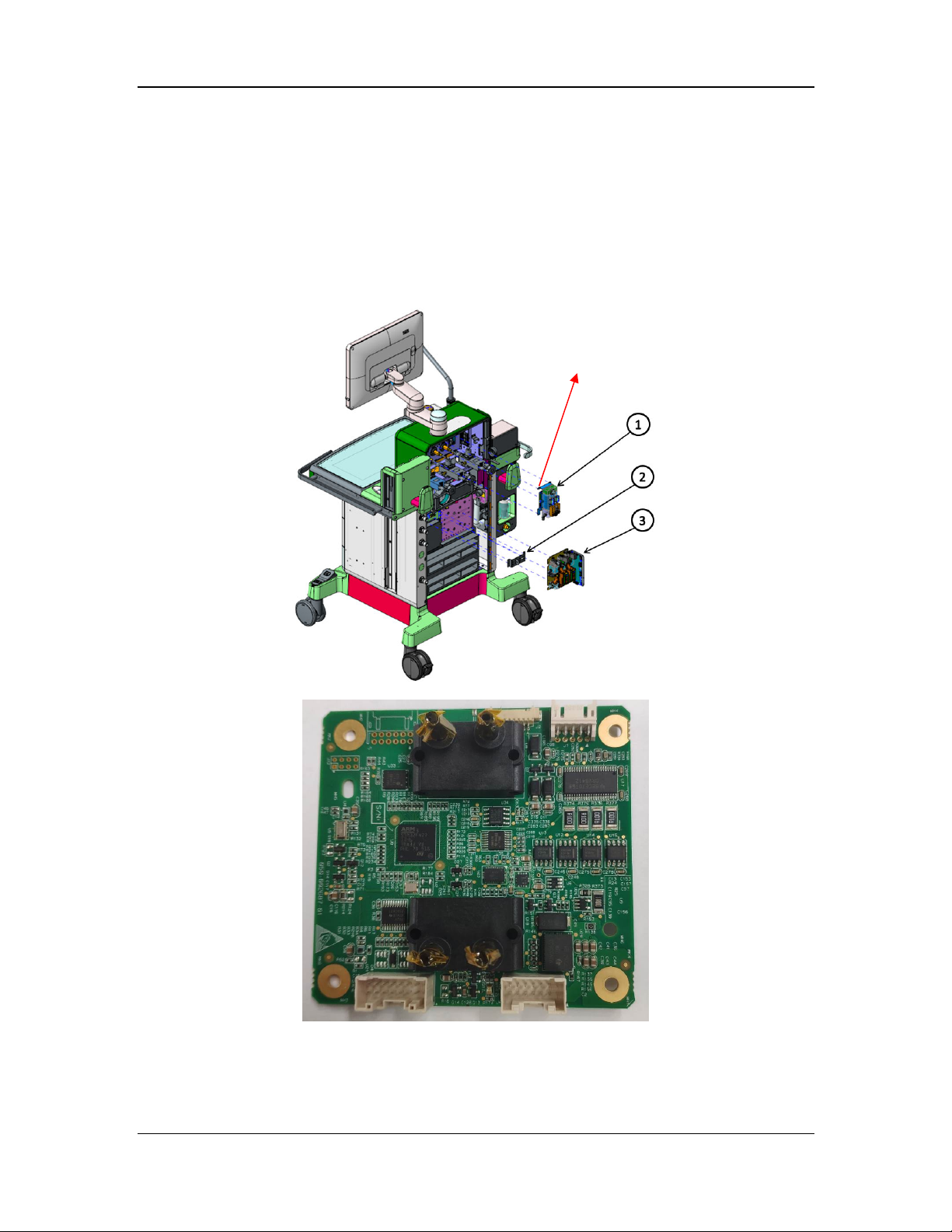
2.2.6 Auxiliary O2/Air System
2.2.6.1 Auxiliary Flowmeter Monitoring Board
The auxiliary flowmeter monitoring board is the core control part of the auxiliary flowmeter of
the anesthesia machine. It is mainly used at a low flow of 0–15 L/min and can work
independently. The flow sensor is welded on the board. The auxiliary flowmeter monitoring
board controls the O2/air flow through the proportional valve, and monitors and feeds back the
O2/air flow through the flow sensor. In addition, the auxiliary flowmeter monitoring board also
drives the three-way valve. This board is configured with auxiliary O2/air software.
Auxiliary flowmeter monitoring board
Installation position of the auxiliary flowmeter monitoring board
Auxiliary flowmeter monitoring board (top view)
2-38
Page 67
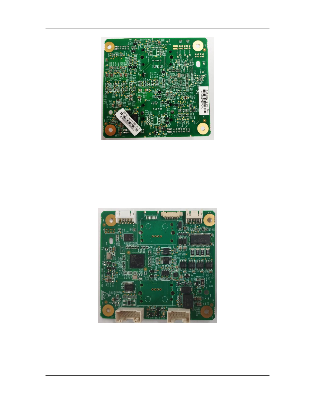
Auxiliary flowmeter monitoring board (bottom view)
2.2.6.2 High-Flow O2 Therapy Monitoring Board
The high-flow O2 therapy monitoring board is the core control part of high-flow O2 therapy of
the anesthesia machine. It is mainly used at a low flow of 0–60 L/min and can work
independently. The flow sensor is not welded on the board. The high-flow O2 therapy monitoring
board controls the O2/air flow through the proportional valve, and monitors and feeds back the
O2/air flow through the flow sensor. In addition, the high-flow O2 therapy monitoring board also
drives the three-way valve. This board is configured with high-flow O2 therapy software.
The high-flow O2 therapy monitoring board is installed in the same position as the auxiliary
O2/air flowmeter monitoring board.
High-flow O2 therapy monitoring board (top view)
2-39
Page 68
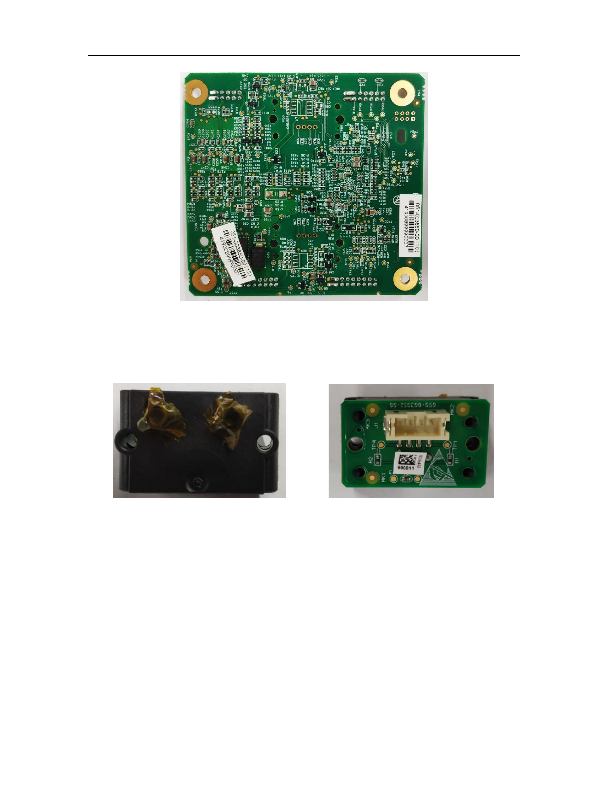
High-flow O2 therapy monitoring board (bottom view)
2.2.6.3 High-Flow Sensor Board
The high-flow sensor board is mainly used to monitor the O2/air branch flow of the high-flow O2
therapy module and feed back the detected signals to the high-flow O2 therapy monitoring board
through the I2C bus.
This board is installed inside the high-flow O2 therapy module.
High-flow sensor board
2-40
Page 69
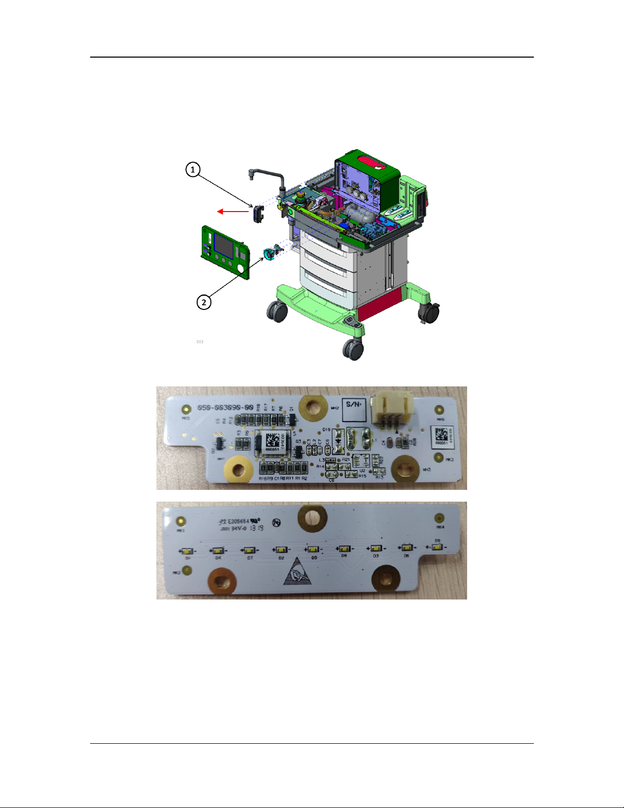
2.2.6.4 Auxiliary Flowmeter Backlight Board
The auxiliary flowmeter backlight board is mainly used to provide lighting for the auxiliary
flowmeter.
The auxiliary flowmeter backlight
board is installed here.
Installation position of the auxiliary flowmeter backlight board
Auxiliary flowmeter backlight board (top view)
Auxiliary flowmeter backlight board (bottom view)
2-41
Page 70
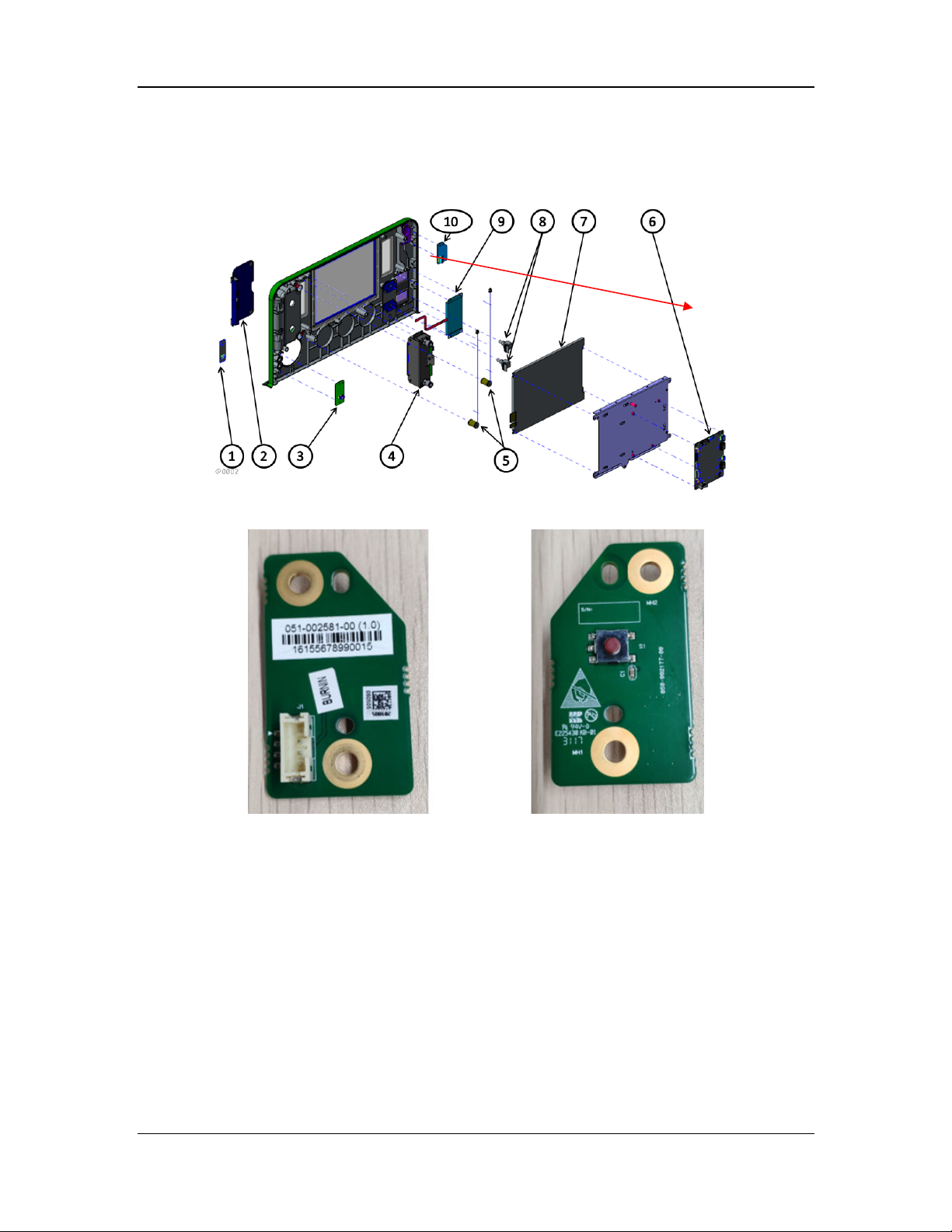
2.2.6.5 Auxiliary O2/Air Keyboard
The auxiliary O2/air keyboard is mainly used to turn on or off the auxiliary O2/air module.
Auxiliary O2/air keyboard
Installation position of the auxiliary O2/air keyboard
Auxiliary O2/air keyboard
2-42
Page 71
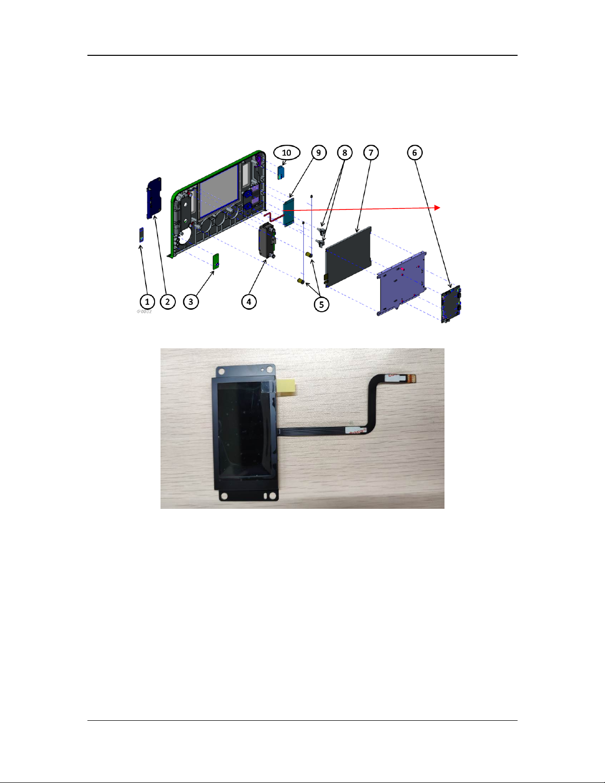
2.2.6.6 Segment Display
The segment display is used to display the total O2/air flow and O2 concentration of the auxiliary
O2/air module.
Segment display
Installation position of the segment display
Segment display
2-43
Page 72
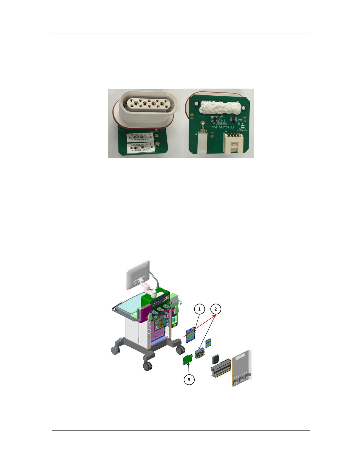
2.2.7 Electronic Vaporizer System (A9)
2.2.7.1 Electronic Vaporizer Base Interface Board
The electronic vaporizer base interface board is used to connect the electronic vaporizer only for
signal transfer. Two electronic vaporizer base interface boards are configured for each machine.
Electronic vaporizer base interface board
2.2.7.2 Electronic Vaporizer
The electronic vaporizer subsystem is located on the right side of the work surface, consisting of
the electronic vaporizer, electronic vaporizer base, and filler. The electronic vaporizer subsystem
is mainly used to accurately output the anesthetic gas concentration, enable users to install,
remove, fill, and drain the vaporizer, as well generate related alarms. The electronic vaporizer
supports three anesthetic agents: isoflurane, sevoflurane, and desflurane. The electronic vaporizer
base provides two canister installation positions.
2.2.8 Other Parts
2.2.8.1 Motherboard
Similar to cable materials, the motherboard is mainly used for signal transfer and power
adaptation for modules. It also contains some current limiting circuits and buzzer alarm circuits.
Motherboard
Installation position of the motherboard
2-44
Page 73
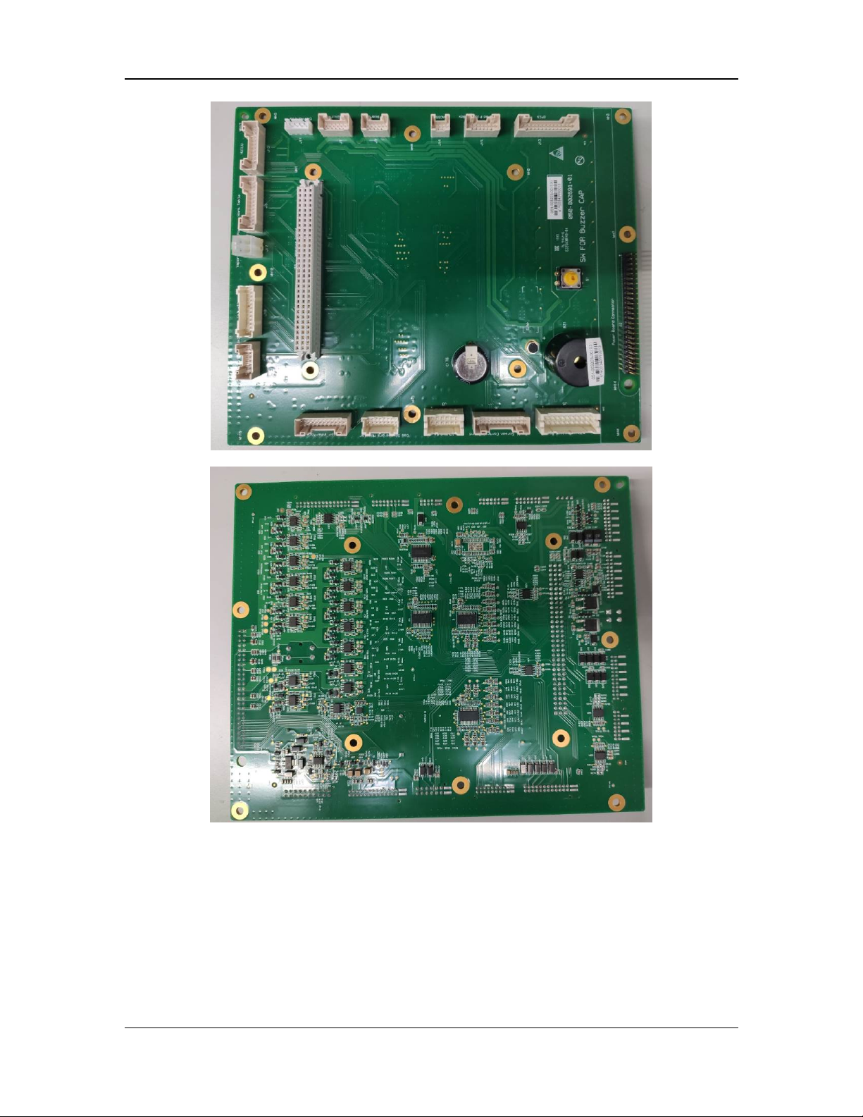
Motherboard (top view)
Motherboard (bottom view)
2-45
Page 74
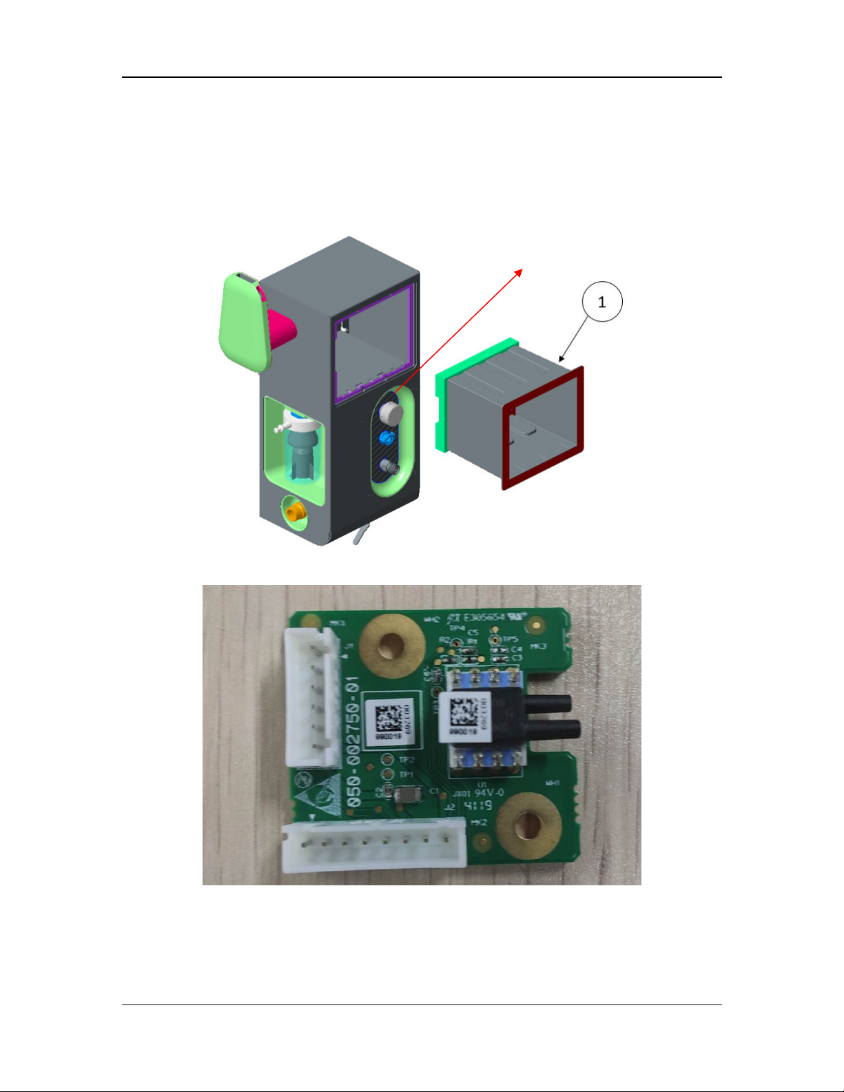
2.2.8.2 AGSS Sensor Board
The AGSS sensor board is used to test the AGSS waste gas flow, which refers to the total flow of
the "drive gas + gas that escapes from the patient circuit + air that is pumped into the hospital
connection pipeline under negative pressure".
The AGSS sensor board
is installed inside.
Installation position of the AGSS sensor board
AGSS sensor board
2-46
Page 75
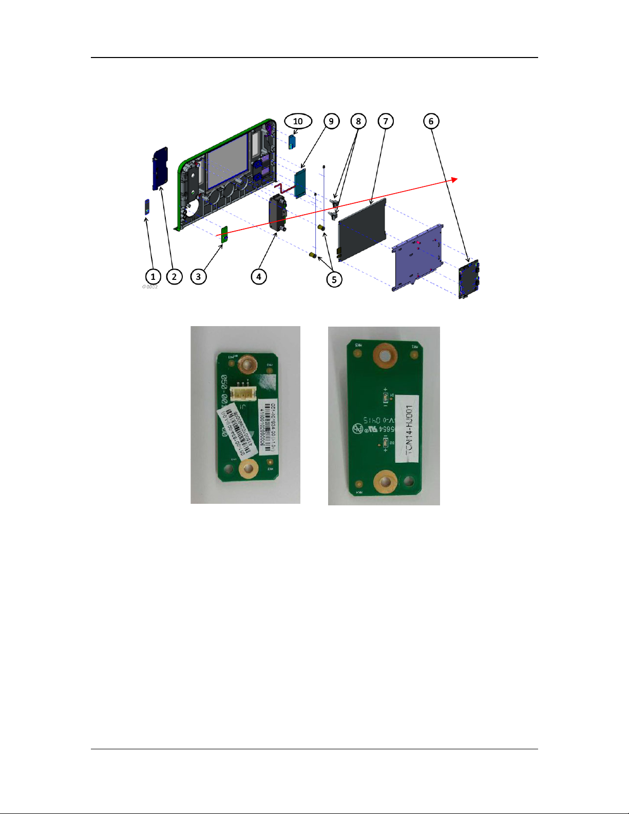
2.2.8.3 Power Indicator Board
Power indicator board
Installation position of the power indicator board
Power indicator board
2-47
Page 76
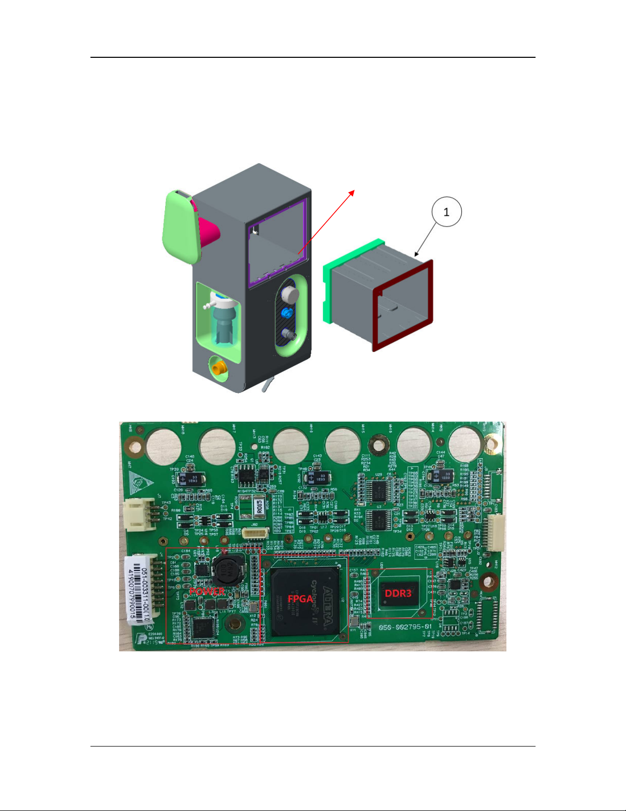
2.2.8.4 Three-Slot Module Rack Backplane
The three-slot module rack backplane is a logical forwarding data board mainly used to power
and communicate with the module rack.
This board is configured with module rack software.
Three-slot module rack backplane
The backplane is installed on the rear.
Installation position of the three-slot module rack backplane
Three-slot module rack backplane
2-48
Page 77
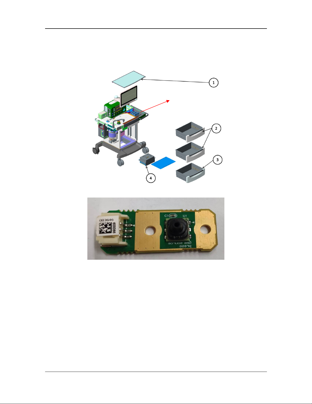
2.2.8.5 EFCS Outlet Pressure Sensor Board
The EFCS outlet pressure sensor board is used to detect the pressure at the EFCS outlet.
The EFCS outlet pressure
sensor board is installed here.
Installation position of the EFCS outlet pressure sensor board
EFCS outlet pressure sensor board
2-49
Page 78
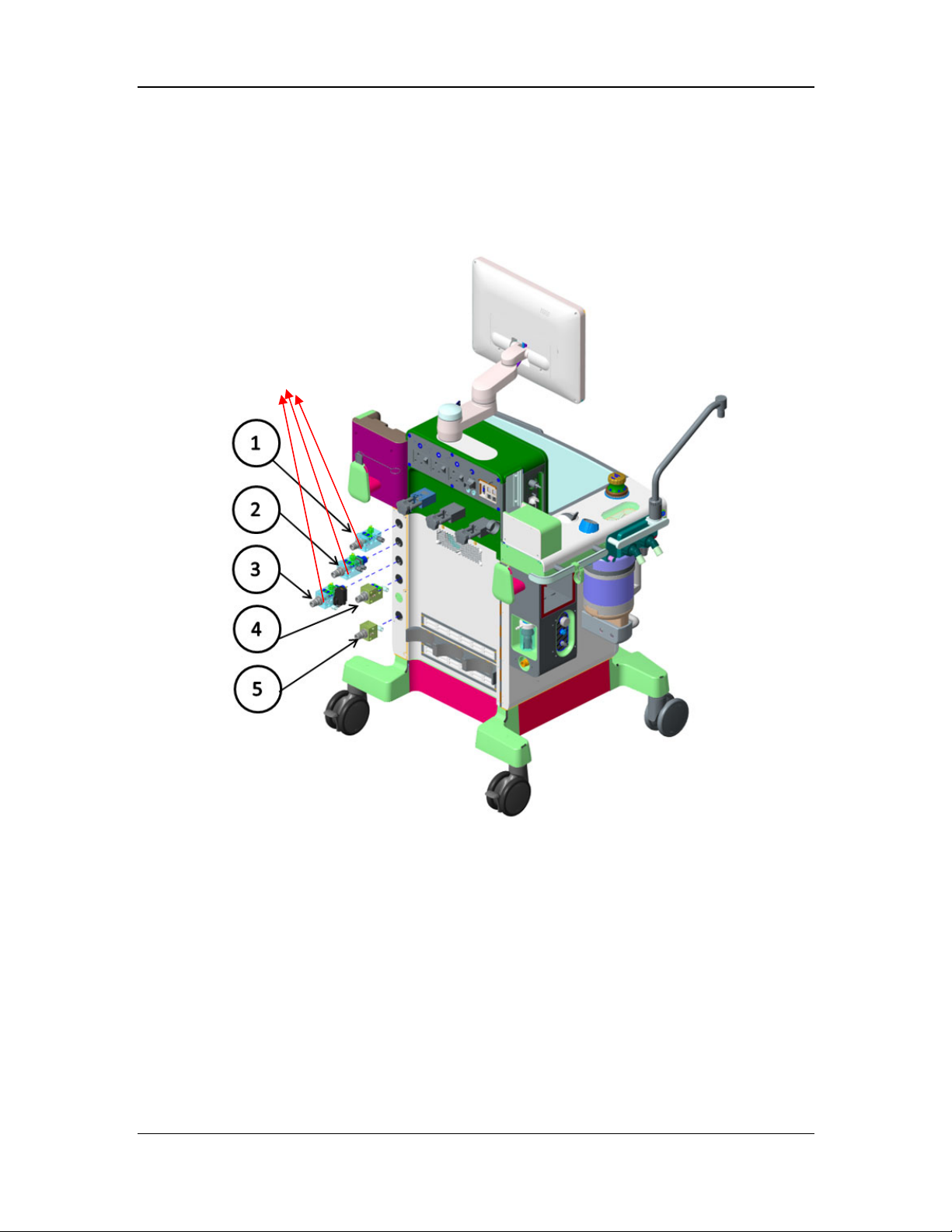
b
2.2.8.6 Gas Inlet Pressure Sensor Board
The gas inlet pressure sensor board is used to detect the pressure at the pipeline gas inlet. It has
the same appearance as the EFCS outlet pressure sensor board but has a different measurement
range. Pay attention to the part numbers during servicing.
The gas inlet pressure sensor
oard is installed here.
Installation position of the gas inlet pressure sensor board
2-50
Page 79
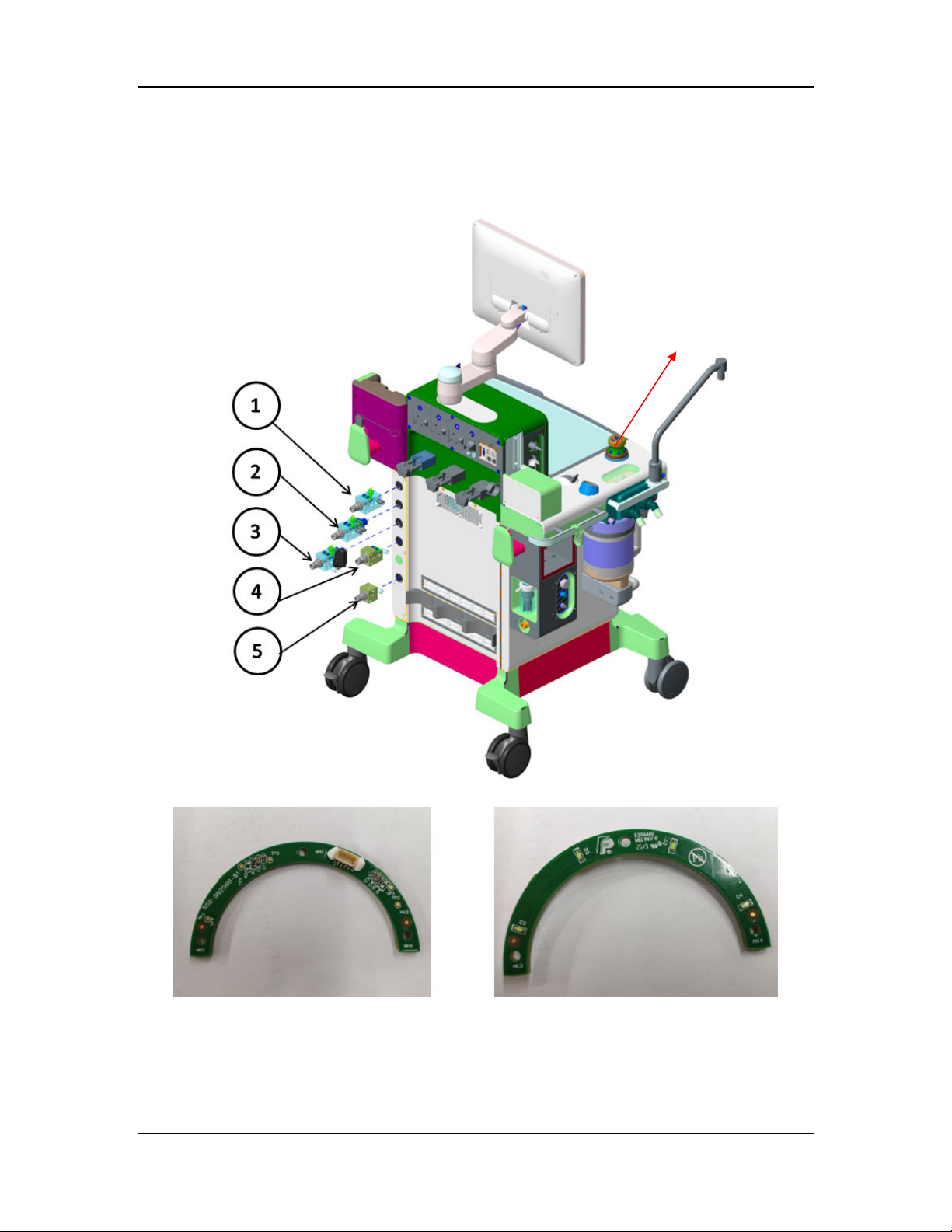
2.2.8.7 APL Lighting Board
The APL lighting board is used to indicate the manual APL knob.
The APL lighting board
is installed here.
Installation position of the APL lighting board
APL lighting board
2.2.8.8 External I/O Interface Board
The external I/O interface board provides external ports, including four USB ports, two network
ports, and one DB9 port (for calibration and device interconnection). No software is configured
for this board.
2-51
Page 80
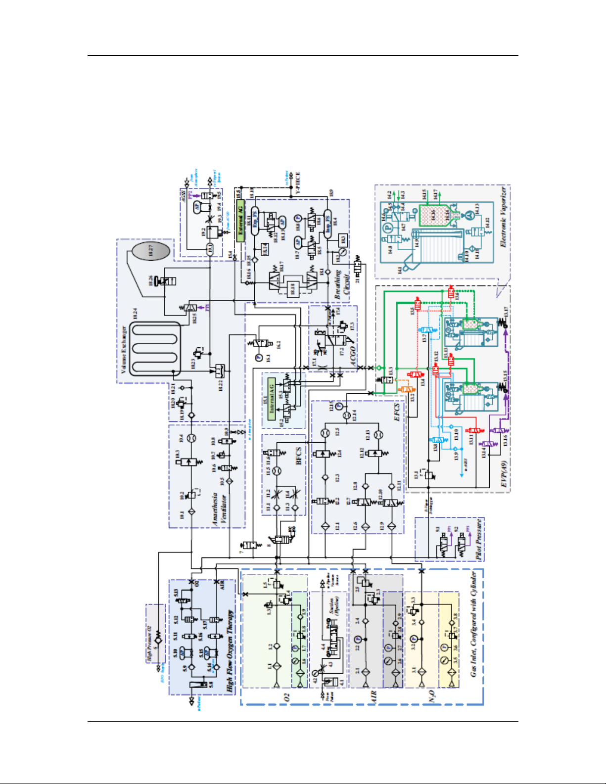
2.3 Pneumatic Part
The A9/A8 anesthesia machine consists of seven subsystems: gas supply, flowmeter, vaporizer,
breathing, auxiliary gas supply, AGSS, and negative pressure suction.
The A9 pneumatic diagram and the list of related parts are shown below:
2-52
Page 81

No. Description No. Description
1.1 Filter 13.2 2/3 Switch-Over Valve
1.2 Check Valve 13.3 Normally Opened Valve
1.3 Pressure Switch 13.4 2/3 Switch-Over Valve
1.4 Pressure Relief Valve 13.5 Normally Closed Valve
1.5 Pressure Regulating Valve 13.6 Normally Closed Valve
1.6 Cylinder Pressure Gauge 13.7 2/3 Switch-Over Valve
1.7 Electronic Pressure Sensor of Cylinder 13.8 2/3 Switch-Over Valve
1.8 Pressure Regulating Valve of Cylinder 13.9 Check Valve
1.9 Check Valve of Cylinder 13.10 Check Valve
1.12 Electronic Pressure Sensor of Pipeline 13.11 2/3 Switch-Over Valve
2.1 Filter 13.12 Normally Closed Valve
2.2 Electronic Pressure Sensor of Pipeline 13.13 Normally Closed Valve
2.3 Pressure Relief Valve 13.14 2/3 Switch-Over Valve
2.4 Check Valve 13.15 Pneumatic Self-Lock Valve
2.5 Pressure Regulating Valve 13.16 2/3 Switch-Over Valve
2.6 Cylinder Pressure Gauge 13.17 Pneumatic Self-Lock Valve
2.7 Electronic Pressure Sensor of Cylinder 14.1 Filling hole
2.8 Pressure Regulating Valve of Cylinder 14.2 Driving gas outlet
2.9 Check Valve 14.3 Driving gas inlet
3.1 Filter 14.4 Filter
3.2 Electronic Pressure Sensor of Pipeline 14.5 Filter
3.3 Pressure Relief Valve 14.6 Switch-cover-linked pressure supply
and relief valve
3.4 Check Valve 14.7 Pressure sensor
3.5 Cylinder Pressure Gauge 14.8 Normally-closed switch valve
3.6 Electronic Pressure Sensor of Cylinder 14.9 Capacitive liquid level sensor
3.7 Pressure Regulating Valve of Cylinder 14.10 Ultrasonic liquid level sensor
3.8 Check Valve 14.11 Filter
4.1 Overfill Protector 14.12 Normally-closed switch valve
4.2 Negative Pressure Gauge 14.13 Spraying control valve
4.3 Negative Pressure Regulating Switch 14.14 Infrared counter
4.4 Mode Selector Switch 14.15 Fresh Gas Inlet
2-53
Page 82

5.8 Float Flowmeter(0-60LPM) 14.16 Anesthetic mixing chamber
5.9 Check Valve 14.17 Mixed gas outlet
5.10 Differential Pressure Gauge 15.1 Internal AG
5.11 Proportional Valve 15.2 2/3 Switch-Over Valve
5.12 Pilot Normally Closed Valve 15.3 2/3 Switch-Over Valve
5.13 Pilot 2/3 Switch-Over Valve 15.4 Self-sealing Sampling Tube
5.14 Check Valve 15.5 External AG
5.15 Differential Pressure Gauge 16.1 Pressure Sensor
5.16 Proportional Valve 16.2 2/3 Switch-Over Valve
5.17 Pilot Normally Closed Valve 17.1 Flow Restrictor
6 High-Pressure O2 Output 17.2 ACGO Switch
7 O2 Flush 17.3 11kPa (112 cmH2O) Pressure Relief
Valve
8 System Switch 17.4 ACGO Port
9.1 Pilot-Operated Valve of Manual/Auto
Switch
9.2 Pilot-Operated Valve of AGSS On/Off 18.2 Airway Pressure Gauge
10.1 Filter 18.3 O2 Sensor
10.2 Pressure Regulating Valve 18.4 Differential Pressure Gauge of
10.3 Proportional Valve 18.5 2/3 Switch-Over Valve
10.4 Flow Sensor 18.6 2/3 Switch-Over Valve
10.5 Filter 18.7 Inspiration Flow Sensor
10.6 Normally-Closed Switch Valve 18.8 Pressure Sensor
10.7 Pressure Switch 18.9 Inspiratory Port
10.8 Proportional Valve 18.10 Expiratory Port
10.9 Flow Restrictor 18.11 Differential Pressure Gauge of
11.1 Check Valve 18.12 2/3 Switch-Over Valve
11.2 O2 Needle Valve 18.13 Expiration Flow Sensor
11.3 Check Valve 18.14 Watertrap
18.1 Check Valve
Inspiration
Expiration
11.4 Air Needle Valve 18.15 Check Valve
11.5 Float Flowmeter (0-15LPM) 18.16 Self-Sealing Sampling Tube
11.6 Normally-Open Switch Valve 18.17 Bypass
12.1 Filter 18.18 CO2 Absorber Canister
12.2 Normally-Closed Switch Valve 18.19 Check Valve
2-54
Page 83

12.3 Check Valve 18.20 11kPa (112 cmH2O) Pressure Relief
Valve
12.4 Proportional Valve 18.21 Check Valve
12.5 Flow Sensor 18.22 Expiratory Valve
12.6 Filter 18.23 1kPa (10 cmH2O) Pressure Relief
Valve
12.7 2/3 Switch-Over Valve 18.24 Volume Exchanger (VE)
12.8 Check Valve 18.25 Manual/Auto Switch Valve
12.9 Filter 18.26 APL Valve
12.10 2/3 Switch-Over Valve 18.27 Manual Bag
12.11 Check Valve 19.1 Gas Reservoir
12.12 Proportional Valve 19.2 Waste Gas Discharging Y-Piece
12.13 Flow Sensor 19.3 Negative Pressure Regulating Valve
12.14 Flow Sensor 19.4 Differential Negative Pressure
Gauge
12.15 Pressure Sensor 19.5 Pilot-Operated AGSS Valve
13.1 Pressure Regulating Valve 21 Normally-Closed Switch Valve
2-55
Page 84
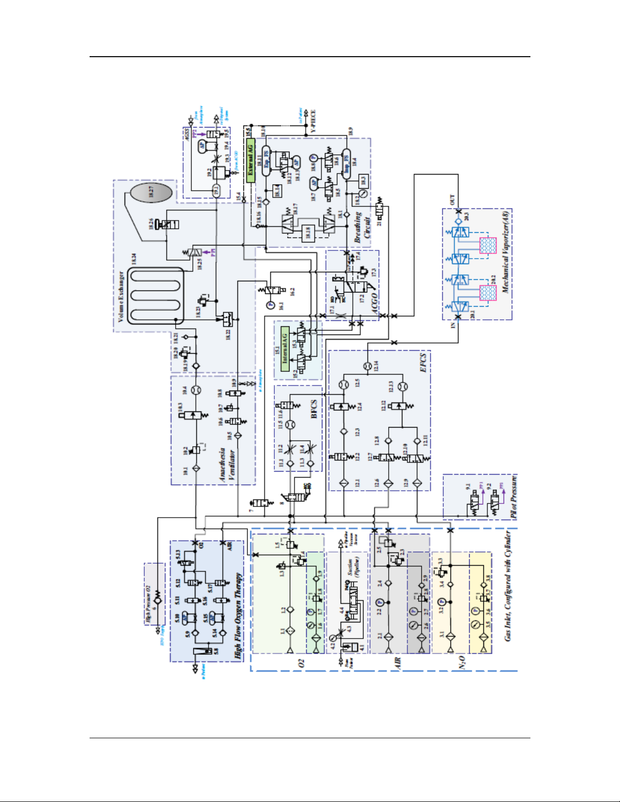
The A8 pneumatic diagram and the list of related parts are shown below:
2-56
Page 85

No. Description No. Description
1.1 Filter 12.1 Filter
1.2 Check Valve 12.2 Normally-Closed Switch Valve
1.3 Pressure Switch 12.3 Check Valve
1.4 Pressure Relief Valve 12.4 Proportional Valve
1.5 Pressure Regulating Valve 12.5 Flow Sensor
1.6 Cylinder Pressure Gauge 12.6 Filter
1.7 Electronic Pressure Sensor of Cylinder 12.7 2/3 Switch-Over Valve
1.8 Pressure Regulating Valve of Cylinder 12.8 Check Valve
1.9 Check Valve of Cylinder 12.9 Filter
1.12 Electronic Pressure Sensor of Pipeline 12.10 2/3 Switch-Over Valve
2.1 Filter 12.11 Check Valve
2.2 Electronic Pressure Sensor of Pipeline 12.12 Proportional Valve
2.3 Pressure Relief Valve 12.13 Flow Sensor
2.4 Check Valve 12.14 Flow Sensor
2.5 Pressure Regulating Valve 15.1 Internal AG
2.6 Cylinder Pressure Gauge 15.2 2/3 Switch-Over Valve
2.7 Electronic Pressure Sensor of Cylinder 15.3 2/3 Switch-Over Valve
2.8 Pressure Regulating Valve of Cylinder 15.4 Self-sealing Sampling Tube
2.9 Check Valve 15.5 External AG
3.1 Filter 16.1 Pressure Sensor
3.2 Electronic Pressure Sensor of Pipeline 16.2 2/3 Switch-Over Valve
3.3 Pressure Relief Valve 17.1 Flow Restrictor
3.4 Check Valve 17.2 ACGO Switch
3.5 Cylinder Pressure Gauge 17.3 11kPa (112 cmH2O) Pressure Relief
Valve
3.6 Electronic Pressure Sensor of Cylinder 17.4 ACGO Port
3.7 Pressure Regulating Valve of Cylinder 18.1 Check Valve
3.8 Check Valve 18.2 Airway Pressure Gauge
4.1 Overfill Protector 18.3 O2 Sensor
4.2 Negative Pressure Gauge 18.4 Differential Pressure Gauge of
Inspiration
4.3 Negative Pressure Regulating Switch 18.5 2/3 Switch-Over Valve
4.4 Mode Selector Switch 18.6 2/3 Switch-Over Valve
2-57
Page 86

5.8 Float Flowmeter(0-60LPM) 18.7 Inspiration Flow Sensor
5.9 Check Valve 18.8 Pressure Sensor
5.10 Differential Pressure Gauge 18.9 Inspiratory Port
5.11 Proportional Valve 18.10 Expiratory Port
5.12 Pilot Normally Closed Valve 18.11 Differential Pressure Gauge of
Expiration
5.13 Pilot 2/3 Switch-Over Valve 18.12 2/3 Switch-Over Valve
5.14 Check Valve 18.13 Expiration Flow Sensor
5.15 Differential Pressure Gauge 18.14 Watertrap
5.16 Proportional Valve 18.15 Check Valve
5.17 Pilot Normally Closed Valve 18.16 Self-Sealing Sampling Tube
6 High-Pressure O2 Output 18.17 Bypass
7 O2 Flush 18.18 CO2 Absorber Canister
8 System Switch 18.19 Check Valve
9.1 Pilot-Operated Valve of Manual/Auto
Switch
9.2 Pilot-Operated Valve of AGSS On/Off 18.21 Check Valve
10.1 Filter 18.22 Expiratory Valve
10.2 Pressure Regulating Valve 18.23 1kPa (10 cmH2O) Pressure Relief
10.3 Proportional Valve 18.24 Volume Exchanger (VE)
10.4 Flow Sensor 18.25 Manual/Auto Switch Valve
10.5 Filter 18.26 APL Valve
10.6 Normally-Closed Switch Valve 18.27 Manual Bag
10.7 Pressure Switch 19.1 Gas Reservoir
10.8 Proportional Valve 19.2 Waste Gas Discharging Y-Piece
10.9 Flow Restrictor 19.3 Negative Pressure Regulating Valve
11.1 Check Valve 19.4 Differential Negative Pressure Gauge
11.2 O2 Needle Valve 19.5 Pilot-Operated AGSS Valve
11.3 Check Valve 20.1 Vaporizer Bypass
11.4 Air Needle Valve 20.2 Mechanical Vaporizer
18.20 11kPa (112 cmH2O) Pressure Relief
Valve
Valve
11.5 Float Flowmeter (0-15LPM) 20.3 Check Valve
11.6 Normally-Open Switch Valve 21 Normally-Closed Switch Valve
2-58
Page 87
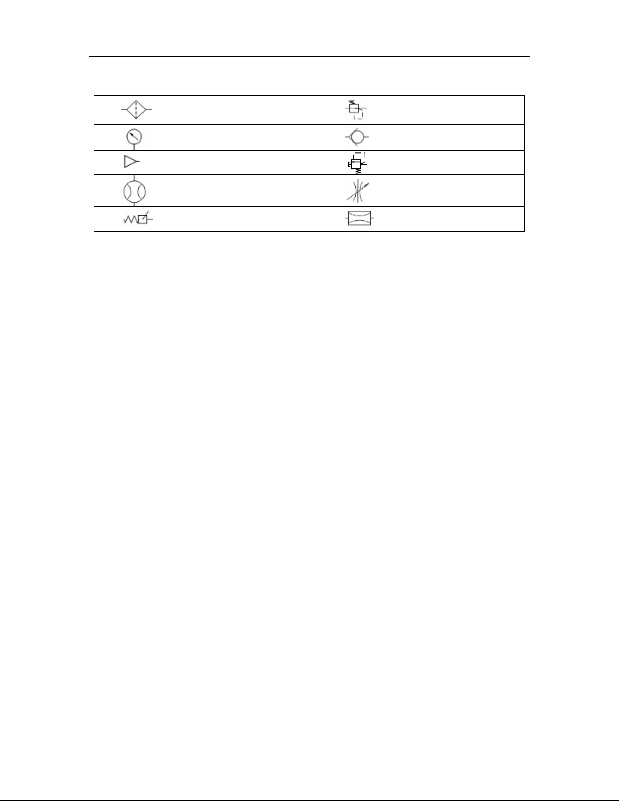
2.3.1 Symbols
Filter
Pressure gauge
Gas supply connector
Flowmeter
Pressure switch
Regulator
Check valve c
Pressure relief valve
Flow control valve
Flow restrictor
2.3.2 Gas Supply Subsystem
The gas supply subsystem is mainly used to provide fresh gas for the patient and drive gas for the
anesthesia ventilator. It consists of the gas inlet assembly, cylinder yoke assembly, ACGO
assembly, O2 flush assembly, and system switch assembly.
2.3.2.1 Gas Inlet Assembly
The gas inlet assembly provides three gases for the anesthesia machine: O2, N2O, and air. Three
types of gas inlet assemblies are available based on different types of gases: O2 inlet assembly,
N2O inlet assembly, and air inlet assembly. The main configuration difference lies in that the O2
inlet assembly is equipped with a gas supply pressure switch and the O2 and air inlet assemblies
each are equipped with a pressure regulating valve. The following figure shows the pneumatic
diagram of the gas inlet assembly based on different configurations and types:
2-59
Page 88
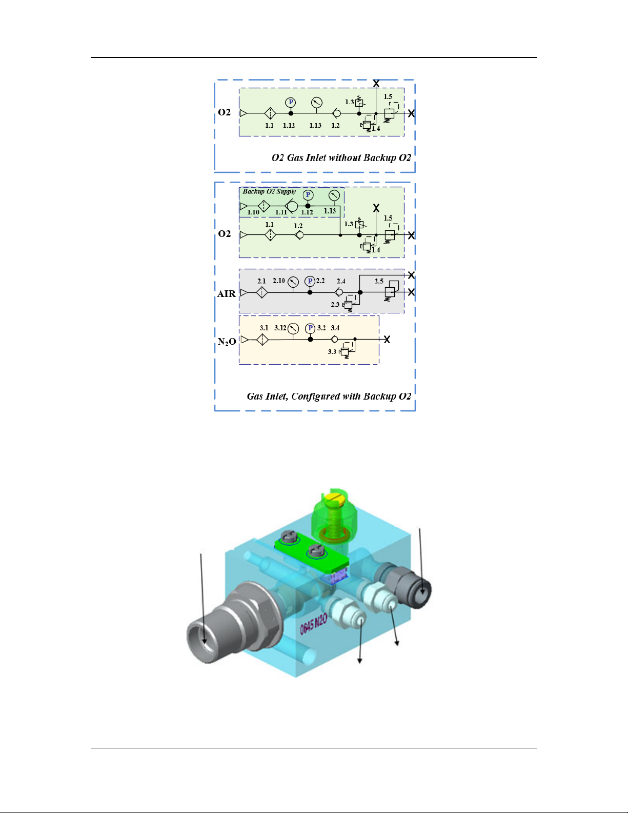
Figure 2 Pneumatic diagram of the gas inlet assembly
As shown in the above figure, the gas inlet assembly consists one or more of the following
components based on different configurations: gas hose connector, filters (1.1, 1.10, 2.1, and 3.1),
check valves (1.2, 1.11, 2.4, and 2.9), pressure relief valves (1.4, 2.3, and 3.3), regulators (1.5 and
2.5), pressures switch (1.3), and pressure sensors (1.12, 2.10, and 3.2). Structural diagrams of the
gas inlet assemblies are shown below.
N2O inlet
Outlet
Pressure test connector
Figure 3 Structural diagram of the N2O inlet assembly
N2O cylinder inlet
2-60
Page 89
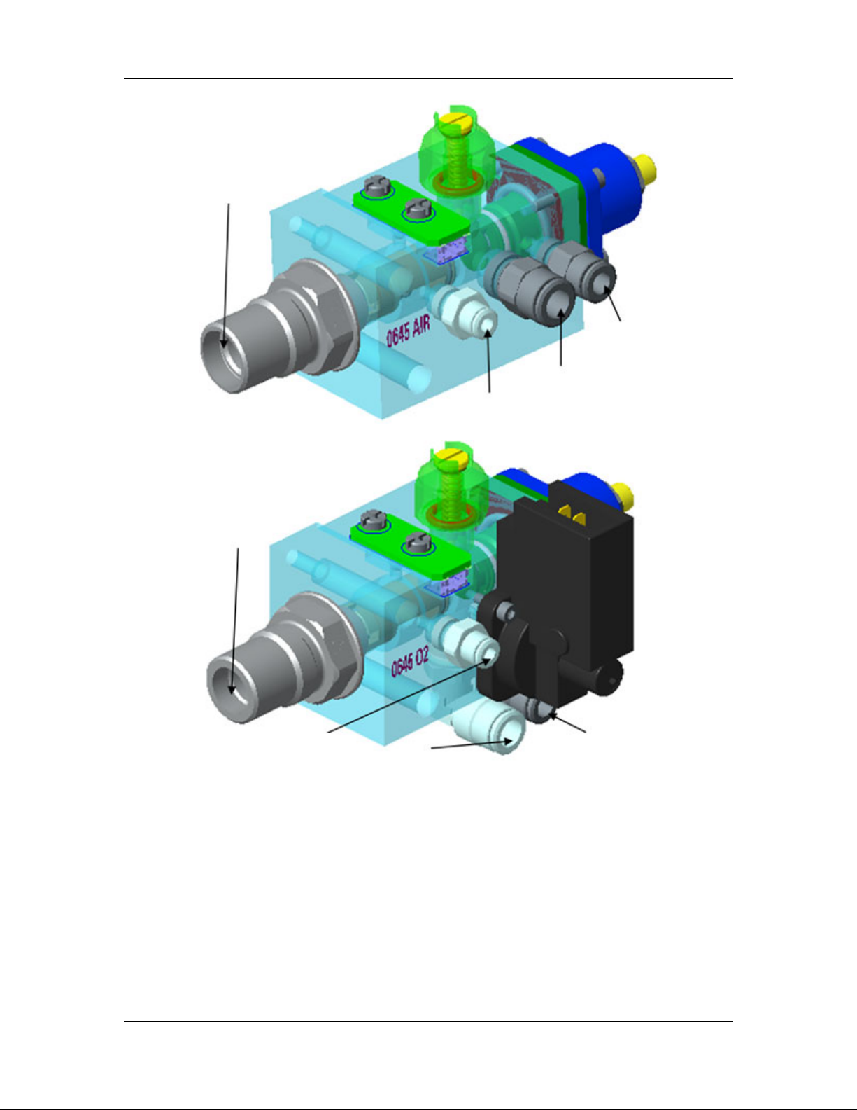
Air inlet
EFCS and negative
pressure suction outlet
Air cylinder inlet
Pressure test connector
Figure 4 Structural diagram of the air inlet assembly
O2 inlet
Pressure test connector
Figure 5 Structural diagram of the O2 inlet assembly
Backup O2 and cylinder inlet
Outlet
2-61
Page 90
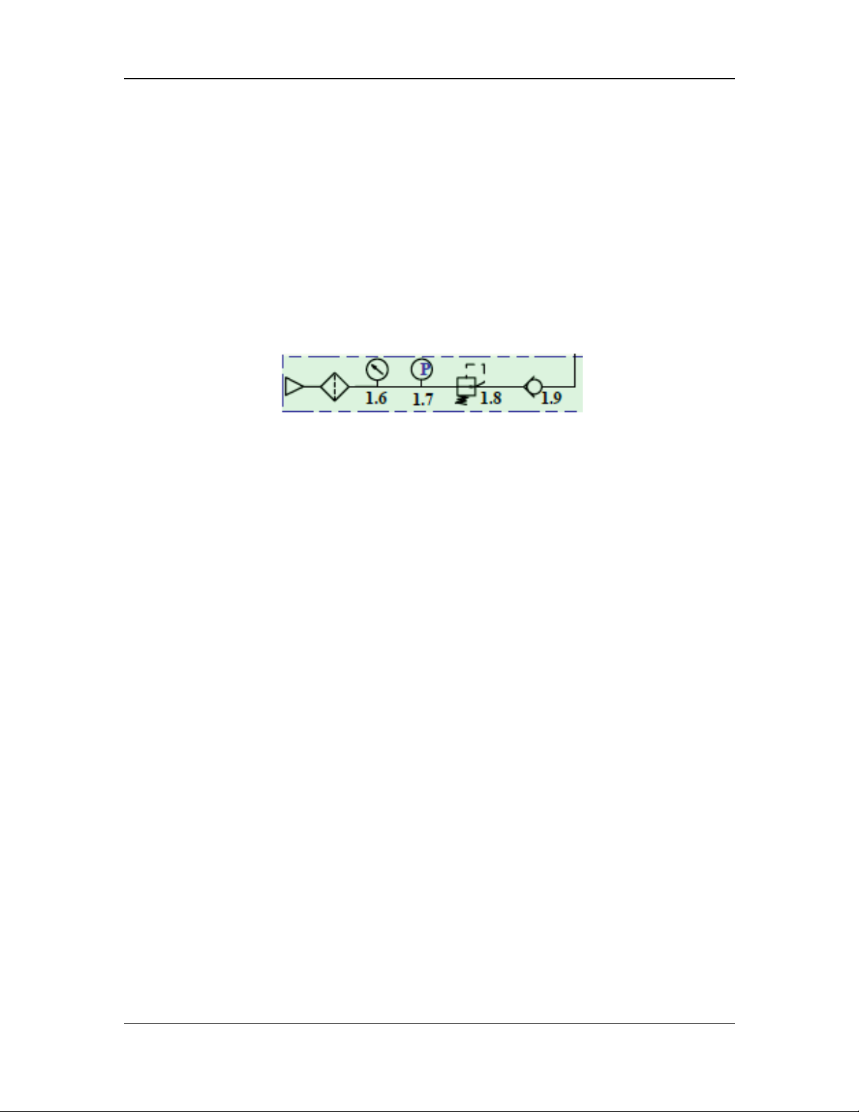
2.3.2.2 Cylinder Yoke Assembly
The cylinder yoke assembly is used to connect a high-pressure cylinder to the anesthesia machine,
so that the anesthesia machine can use O2, air, and N2O supplied by the high-pressure cylinder.
The high-pressure cylinder is connected to the cylinder yoke by means of pin-indexed yoke
connection, which is sealed by the end face of a nylon pad and tightened by using a pentagon
knob. High-pressure gas in the cylinder is purified through the filter in the cylinder yoke and then
enters the pressure reducing valve. Low-pressure gas flows into the gas inlet assembly through
the check valve. The high pressure gauge and the cylinder yoke assembly are connected through
a high-pressure-resistant copper tube and a corresponding connector to monitor the pressure of
the gas output from the cylinder. In a cylinder yoke equipped with a high pressure gauge and an
electronic pressure sensor, the high pressure gauge displays the gas pressure, and the electronic
pressure sensor also displays the detected pressure on the display. The following figure shows the
pneumatic diagram (O2) of the cylinder yoke assembly:
Figure 6 Pneumatic diagram of the cylinder yoke assembly
The cylinder yoke assembly consists of four components: pressure reducing valve (1.8), high
pressure gauge (1.6), electronic pressure sensor (1.7), and check valve (1.9). For a cylinder yoke
equipped with only a mechanical pressure gauge but no electronic pressure sensor, a plug with
the same threads is provided in the position of the connector. The structural diagram of the
cylinder yoke assembly is shown below.
2-62
Page 91
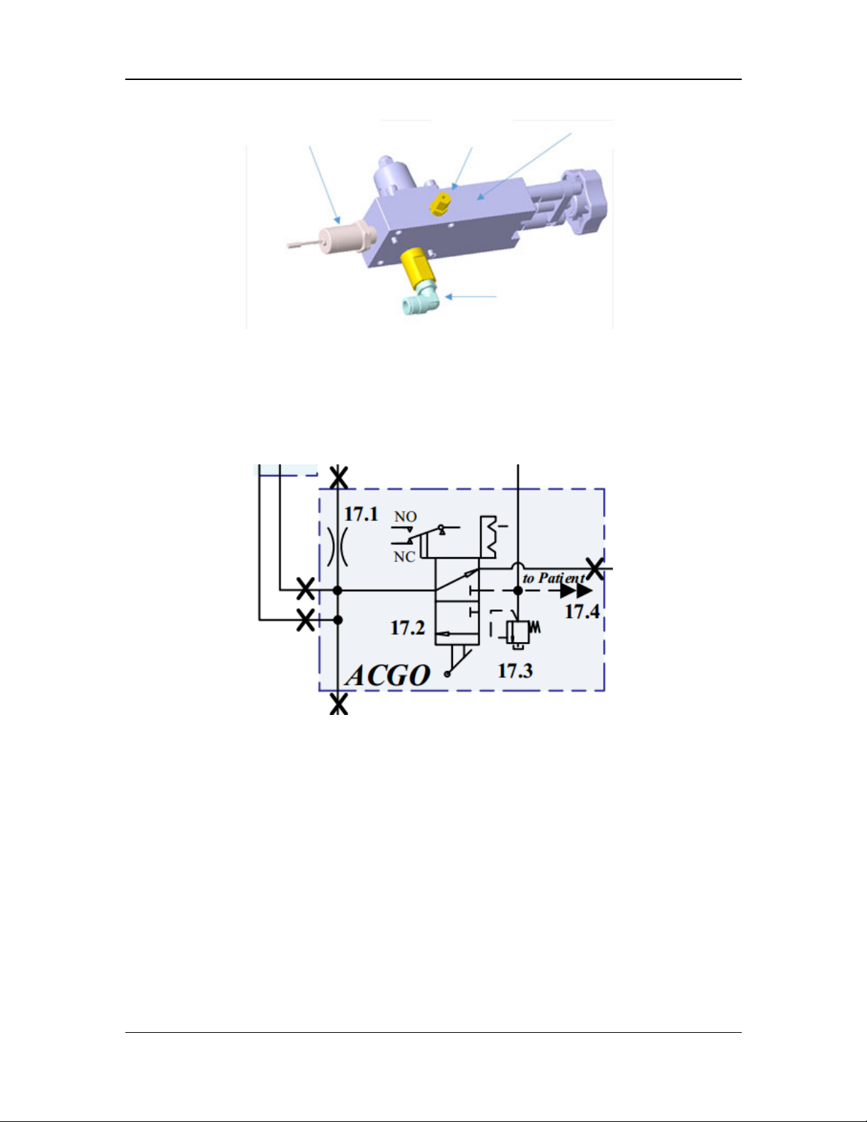
Electronic pressure sensor
Copper tube
connector
Pressure reducer
Check valve
Figure 7 Structural diagram of the cylinder yoke assembly
2.3.2.3 ACGO Assembly
The ACGO assembly outputs the gas flowing through the vaporizer manifold and the flushed O2
to the breathing circuit or directly to the independent ACGO outlet. The ACGO assembly also
provides an AG module sampling connector. The pneumatic diagram of the ACGO assembly is
shown below.
Figure 8 Pneumatic diagram of the ACGO assembly
The ACGO assembly consists of the knob, 11 kPa (112 cmH
O) pressure relief valve (17.3),
2
microswitch (17.2), AG module sampling connector, O2 flush inlet, fresh gas inlet, and common
gas outlet. The structural diagram of the ACGO assembly is shown below.
2-63
Page 92
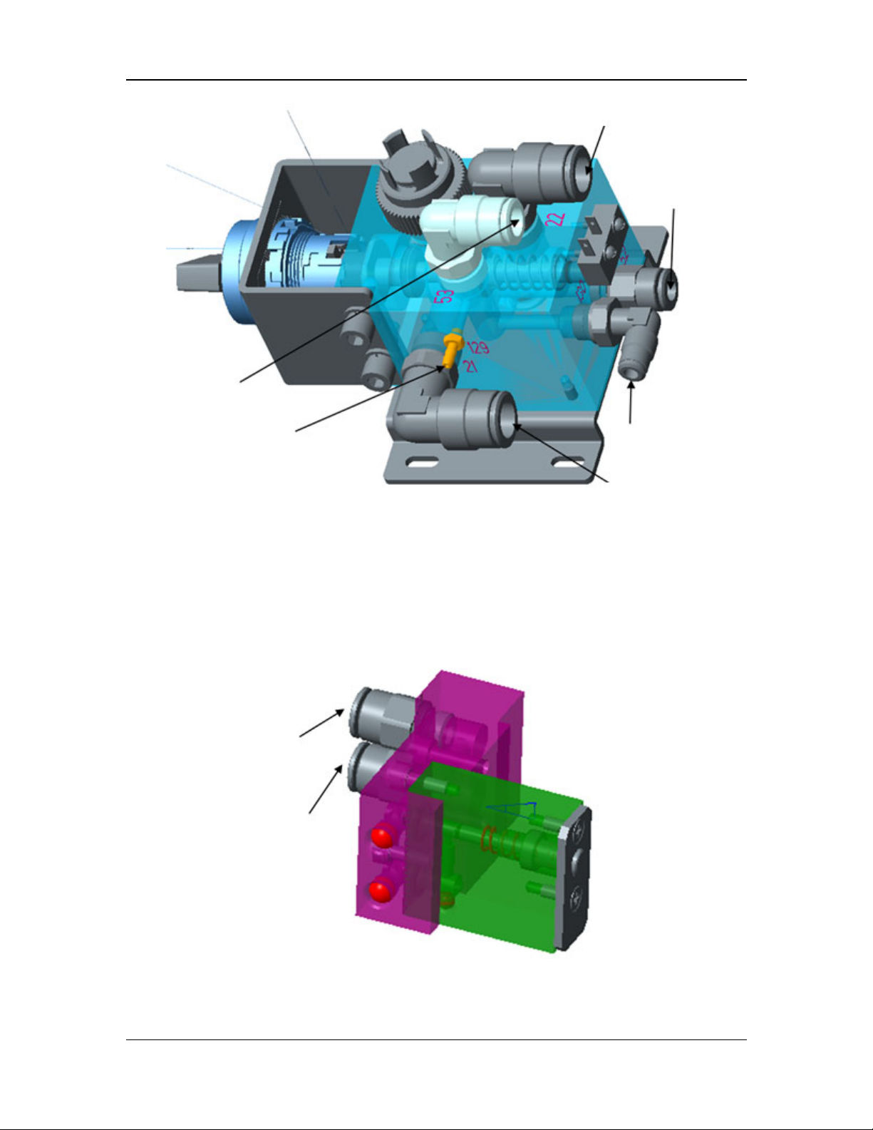
Fresh gas inlet
AG sampling outlet
Patient circuit outlet
Flush inlet
AG sampling inlet
ACGO outlet
Figure 9 Structural diagram of the ACGO assembly
2.3.2.4 O2 Flush Assembly
The O2 flush assembly contains two connectors for connecting to the pressure-regulated output
end of the O2 inlet assembly and the ACGO assembly. The O2 flush assembly controls O2 supply
through a manual push-button switch. It can supply O2 to the breathing system at the flow of
35–50 L/min regardless of whether the machine is turned on or off. The O2 flush assembly
consists of the O2 flush bracket, O2 flush piston, reset spring, and quick connector. The structural
diagram of the O2 flush assembly is shown below.
Inlet
Outlet
Figure 10 Structural diagram of the O2 flush assembly
2-64
Page 93
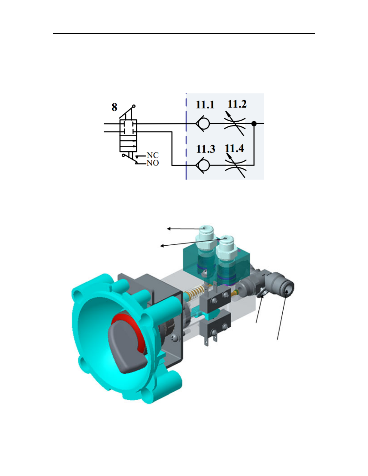
2.3.2.5 System Switch Assembly
The system switch assembly controls fresh gas supply of the breathing system. In addition, it
provides electrical signals of the system switch to realize synchronous on/off control on the
pneumatic system and the circuit system of the anesthesia machine. The system switch outputs
gas for the BFCS. The pneumatic diagram of the system switch assembly is shown below.
Figure 11 Pneumatic diagram of the system switch assembly
The system switch assembly controls O2 and air supply. Both branches are controlled by a
purchased switch knob. During switching, the two limit switches disposed symmetrically also
switch on or off at the same time, realizing on-off control based on electrical signals of the
system. Two check valves (11.1 and 11.3) are integrated at the system switch outlet to prevent air
and O2 inversion. The structural diagram of the system switch assembly is shown below.
O2 limb outlet
Air limb outlet
O2 limb inlet
Air limb inlet
Figure 12 Structural diagram of the system switch assembly
2-65
Page 94
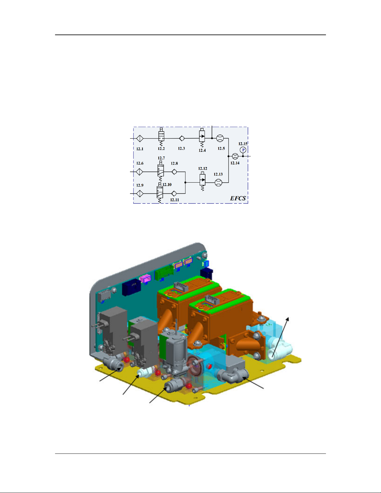
2.3.3 Flowmeter Subsystem
The flowmeter subsystem is mainly used to control the flow of fresh gas and also provides
backup flow control in case of power failure. It consists of the EFCS assembly and BFCS
assembly.
2.3.3.1 EFCS Assembly
The EFCS assembly is used for electronic regulation and monitoring feedback on the flows of the
O2, air, and N2O branches. In addition, it controls the gas mixing ratio, outputs single or mixed
gas, and displays it on the screen. The pneumatic diagram of the EFCS assembly is shown below.
Figure 13 Pneumatic diagram of the EFCS assembly
The EFCS assembly consists of the inlet assembly, outlet assembly, flow sensors (12.5, 12.13,
and 12.14), and pressure sensor (12.15), to control O2, air, and N2O supply separately. In
addition, it provides the input interface and on-off control for the BFCS assembly. The structural
diagram of the EFCS assembly is shown below.
Outlet
Air limb inlet
N2O limb inlet
BFCS inlet
O2 limb inlet
Figure 14 Structural diagram of the EFCS assembly
2-66
Page 95
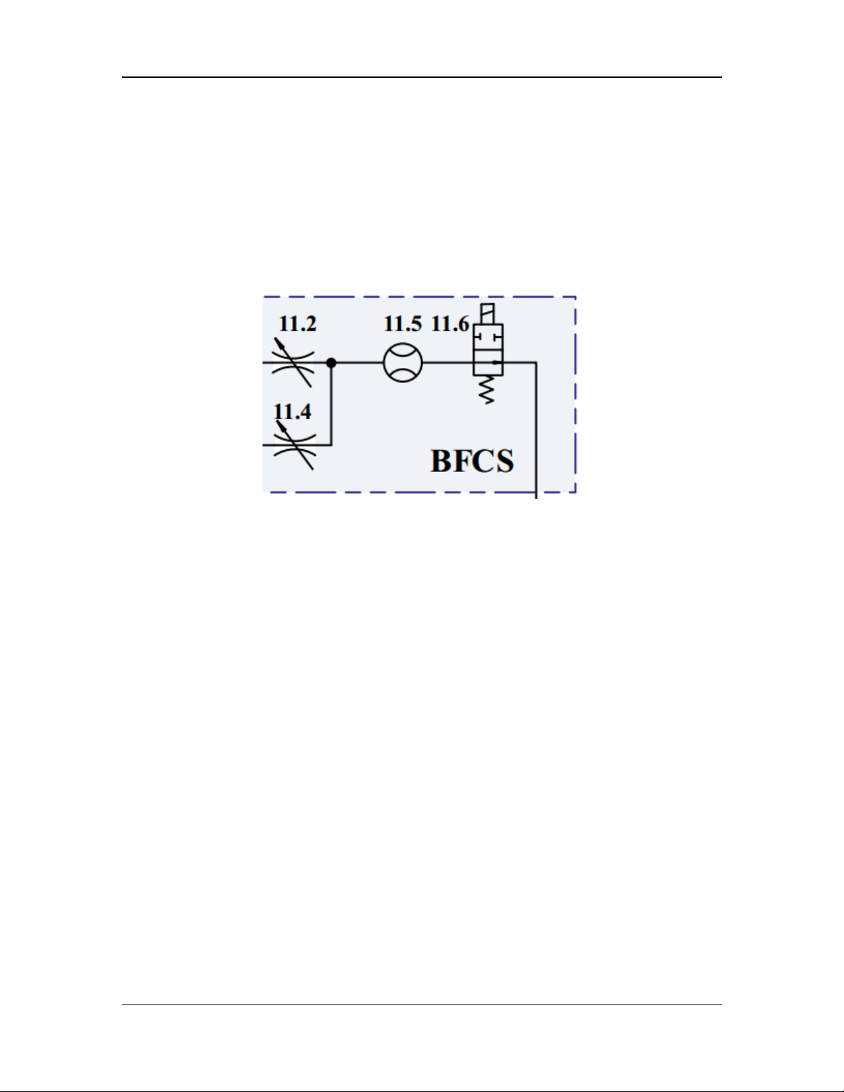
2.3.3.2 BFCS Assembly
The BFCS assembly is used in case of system failure or EFCS assembly failure resulting from
power failure. The BFCS contains two branches: air branch and O2 branch, which are separately
controlled by two needle valves. The gas is supplied by the system switch assembly. The rear
ends of the air needle valve (11.4) and O2 needle valve (11.2) are joined and connected to the
backup flowmeter (11.5), which is a mechanical float flowmeter for indicating the current flow.
The downstream is connected to the EFCS assembly through an NO switch valve (11.6), which is
powered on and closed during normal operation. When the BFCS assembly is activated, the valve
is powered off and automatically open for ventilation. The backup flowmeter is configured with a
backlight board on the rear, which emits light after the BFCS assembly is activated. The
pneumatic diagram of the BFCS assembly is shown below.
Figure 15 Pneumatic diagram of the BFCS assembly
2.3.4 Vaporizer Subsystem
The vaporizer subsystem is mainly used to provide the patient with anesthetic gas at certain
concentration. Different vaporizer subsystems are configured for the A8 and A9 anesthesia
machines. The vaporizer subsystem of the A8 anesthesia machine consists of a mechanical
vaporizer and a mechanical vaporizer manifold assembly. The vaporizer subsystem of the A9
anesthesia machine consists of an electronic vaporizer and an electronic vaporizer manifold
assembly.
2.3.4.1 Mechanical Vaporizer Manifold Assembly (for A8)
The mechanical vaporizer manifold assembly provides a mounting location for the mechanical
vaporizer (installation mode: Selectatec), mixes the anesthetic gas with the O2/air mixture at the
input end to form fresh gas, and delivers the fresh gas to the common gas outlet. The assembly
contains two connectors: one gas inlet connected to the EFCS assembly outlet, and one common
gas outlet serving as an inlet of the ACGO assembly.
In principle, the mechanical vaporizer manifold assembly is a combination of a series of
two-position three-way valves, which are controlled by the springs and vaporizer. When the
vaporizer is not installed, the valves are in a certain state due to the spring force, and the
mechanical vaporizer manifold assembly is a path. When the vaporizer is installed, the status of
the two-position three-way valves switches to make the gas flow through the vaporizer. The
pneumatic diagram is shown below.
2-67
Page 96
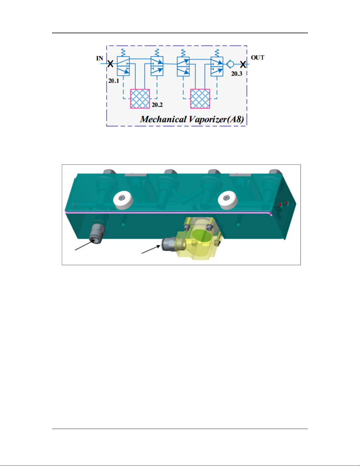
Figure 18 Pneumatic diagram of the mechanical vaporizer manifold assembly
The mechanical vaporizer manifold assembly consists of the check valve assembly, connector
assembly, locking plate assembly, vaporizer manifold, vaporizer pad, and inlet/outlet quick
connectors. The structural diagram of the mechanical vaporizer manifold assembly is shown
below.
Fresh gas inlet
Figure 19 Structural diagram of the mechanical vaporizer manifold assembly
Fresh gas outlet
2.3.4.2 Electronic Vaporizer (for A9)
The electronic vaporizer can accurately feed the anesthetic agent into the anesthesia breathing
circuit at certain concentration. During operating of the electronic vaporizer, the electronic
vaporizer manifold provides 150 kPa (22 psi) drive gas, which flows through the drive gas inlet
(14.3), mechanical pressure relief valve (14.6), pressure sensor (14.7), and drug pool entrance
switch valve (14.8) into the drug pool of the vaporizer. The drive gas drives the anesthetic liquid
in the drug pool to flow through the filter (14.11) and exit safety valve (14.12) into the injector
(14.13), which injects pure anesthetic liquid to the mixing chamber (14.16) at certain frequency.
In addition, the fresh gas of the anesthesia machine enters the mixing chamber through the fresh
air inlet (14.15), and is fully mixed with the anesthetic gas. Then the mixed gas is delivered to the
patient side through the fresh gas outlet (14.17). The pneumatic diagram of the electronic
vaporizer is shown below.
2-68
Page 97
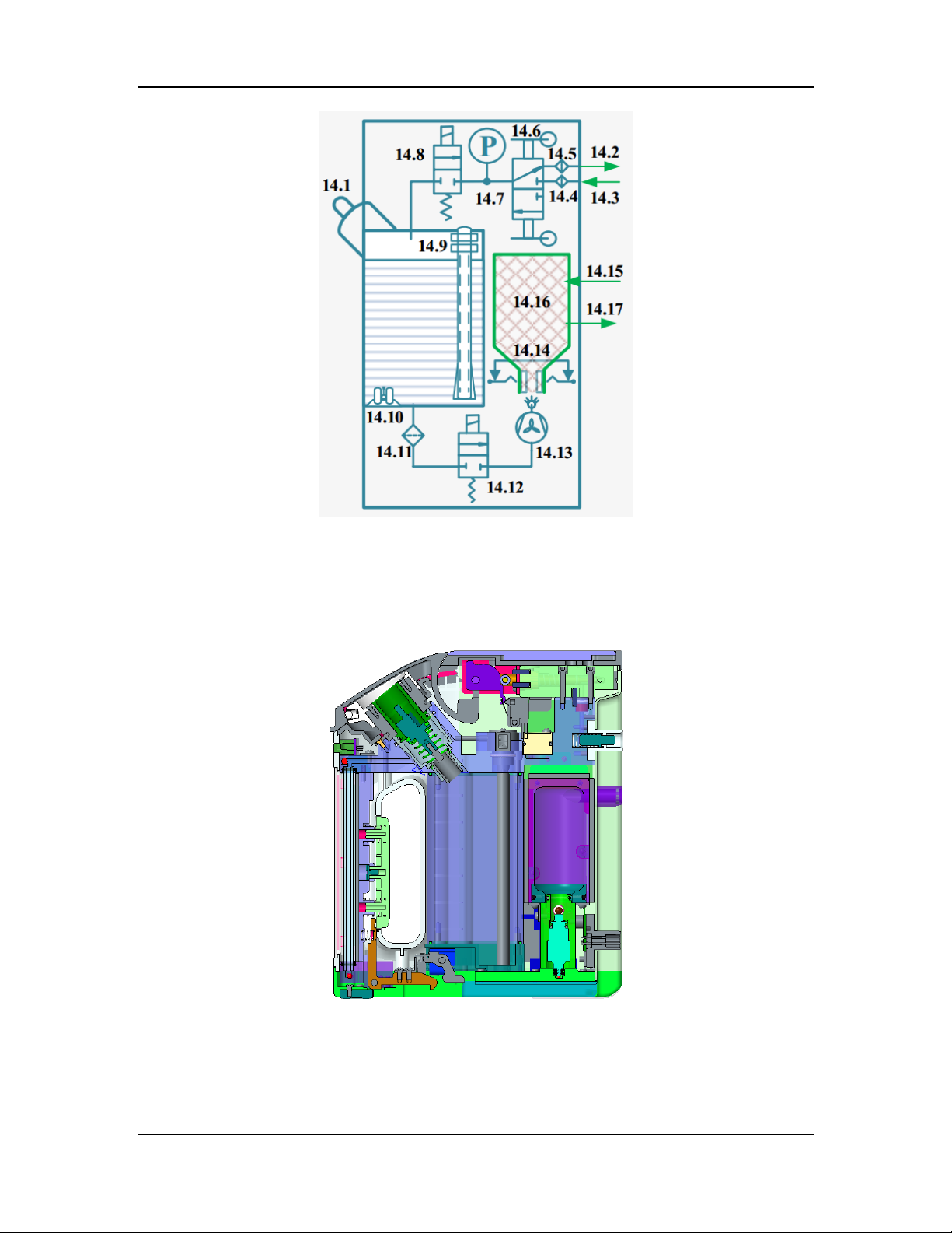
Figure 20 Pneumatic diagram of the electronic vaporizer
The electronic vaporizer consists of the drive gas interfaces (14.2 and 14.3), mechanical pressure
relief assembly (14.6), filling unit (14.1), main pneumatic block assembly, drug pool entrance
safety valve (14.8), drug pool, liquid level monitoring units (ultrasonic low liquid level
monitoring (14.10), capacitive continuous liquid level monitoring (14.9), and glass tube liquid
level display), locking unit, drug pool exit safety valve (14.12), base assembly, and mixing
chamber assembly (14.16). The structural diagram of the electronic vaporizer is shown below.
Figure 21 Structural diagram of the electronic vaporizer
2-69
Page 98
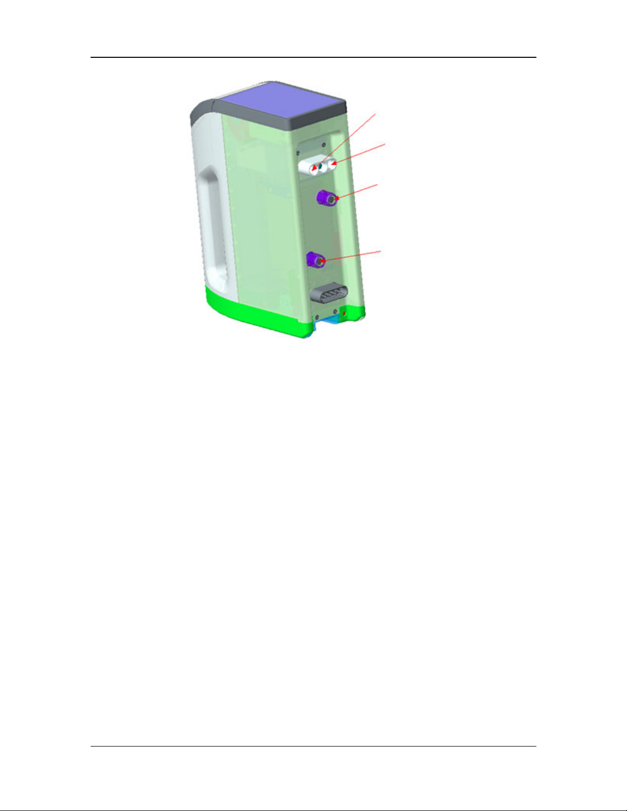
Drive gas inlet
Drive gas outlet
Fresh gas inlet
Fresh gas outlet
Figure 22 Interfaces of the electronic vaporizer
2.3.4.3 Electronic Vaporizer Manifold Assembly (for A9)
The electronic vaporizer manifold assembly provides a mounting location for the electronic
vaporizer, provides driving pressure for the drug pool of the electronic vaporizer, mixes the
O2/air mixture at the input end with the anesthetic gas in the electronic vaporizer to form fresh
gas, and delivers the fresh gas to the common gas outlet.
The schematic diagram of the electronic vaporizer manifold assembly is shown below. The drive
gas from the front gas inlet is divided into six ways. Three ways provide driving pressure for the
large-diameter valve (13.3) in the bypass branch, the large-diameter valves (13.12 and 13.13) in
the branch of canister 1, and the large-diameter valves (13.5 and 13.6) in the branch of canister 2.
Two ways provide driving pressure for the pneumatically-controlled lock (13.15) of canister 1
and the pneumatically-controlled lock (13.17) of canister 2. The remaining one way provides
driving pressure for the electronic vaporizer after the pressure is regulated to 150±5 kPa (22 psi)
through the regulator (13.1). The three-way valve (13.2) is used to switch on/off the bypass
branch. The three-way valve (13.11) is used to switch on/off the branch of canister 1. The
three-way valve (13.4) is used to switch on/off the branch of canister 2. The three-way valve
(13.8) is used to control the pressurization/relief of the drive gas in canister 1. The three-way
valve (13.7) is used to control the pressurization/relief of the drive gas in canister 2. The
three-way valve (13.14) is used to control the pressurization/relief of the
pneumatically-controlled lock drive gas in canister 1. The three-way valve (13.16) is used to
control the pressurization/relief of the pneumatically-controlled lock drive gas in canister 2. The
large-diameter valves and three-way valves are integrated in the electronic vaporizer control
module for controlling the gas from the electronic vaporizer to flow through the branch of
canister 1, the branch of canister 2, or the bypass branch, and controlling the pressurization/relief
of the electronic vaporizer drive gas as well as the locking/unlocking of the
pneumatically-controlled lock. The pneumatically-controlled lock (13.15) of canister 1 and
pneumatically-controlled lock (13.17) of canister 2 are used to lock the electronic vaporizer
during the operation of the electronic vaporizer, to prevent accidental unplugging during the
operation.
2-70
Page 99
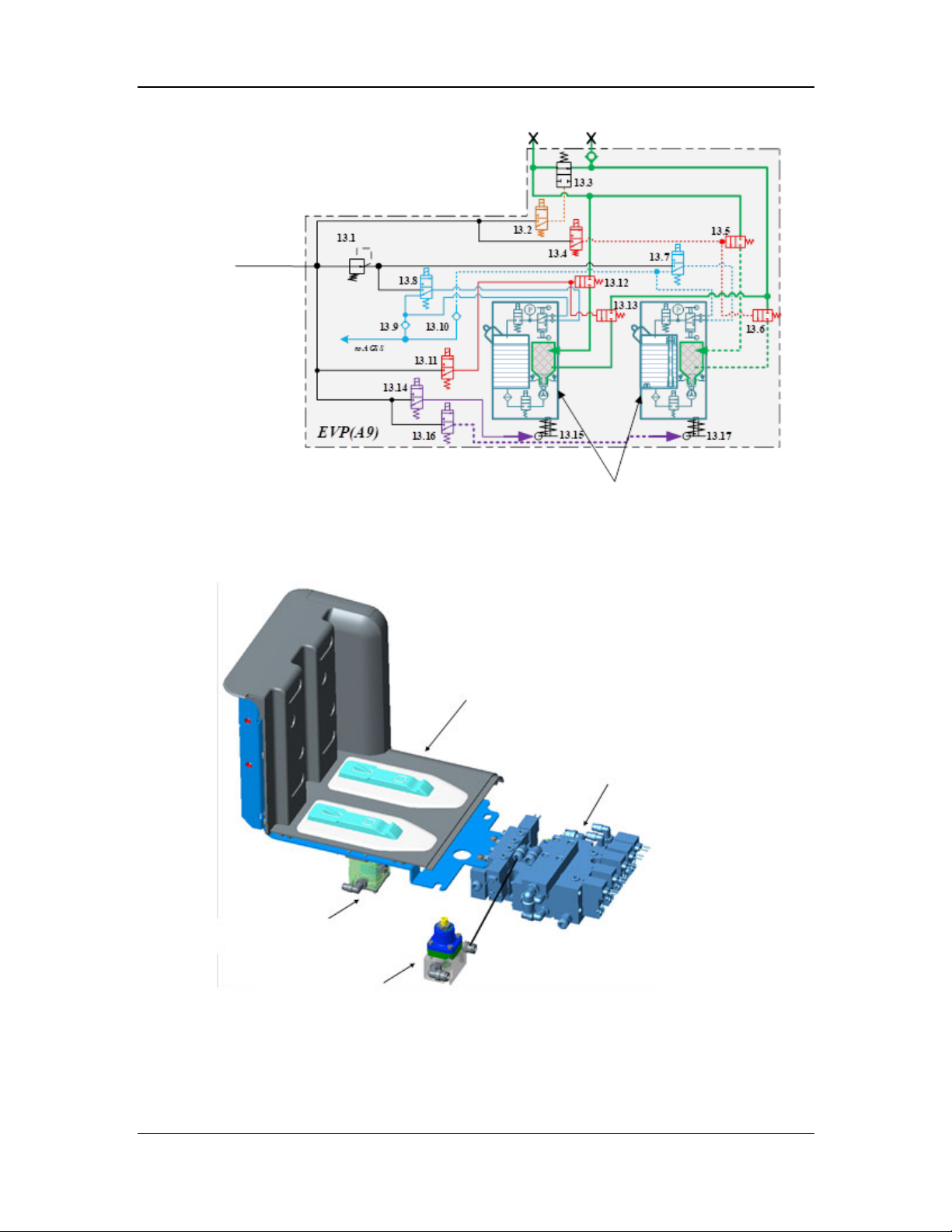
Gas inlet
Drive gas
Figure 23 Pneumatic diagram of the electronic vaporizer manifold assembly
The electronic vaporizer manifold assembly consists of the electronic vaporizer manifold,
pneumatically-controlled locks (13.15 and 13.17), pressure regulator (13.1), and control module.
The structural diagram is shown below.
Gas outlet
Electronic vaporizer
Electronic vaporizer manifold
Electronic vaporizer control module
Pneumatically-controlled lock
Pressure regulator
Figure 24 Structural diagram of the electronic vaporizer manifold assembly
2-71
Page 100
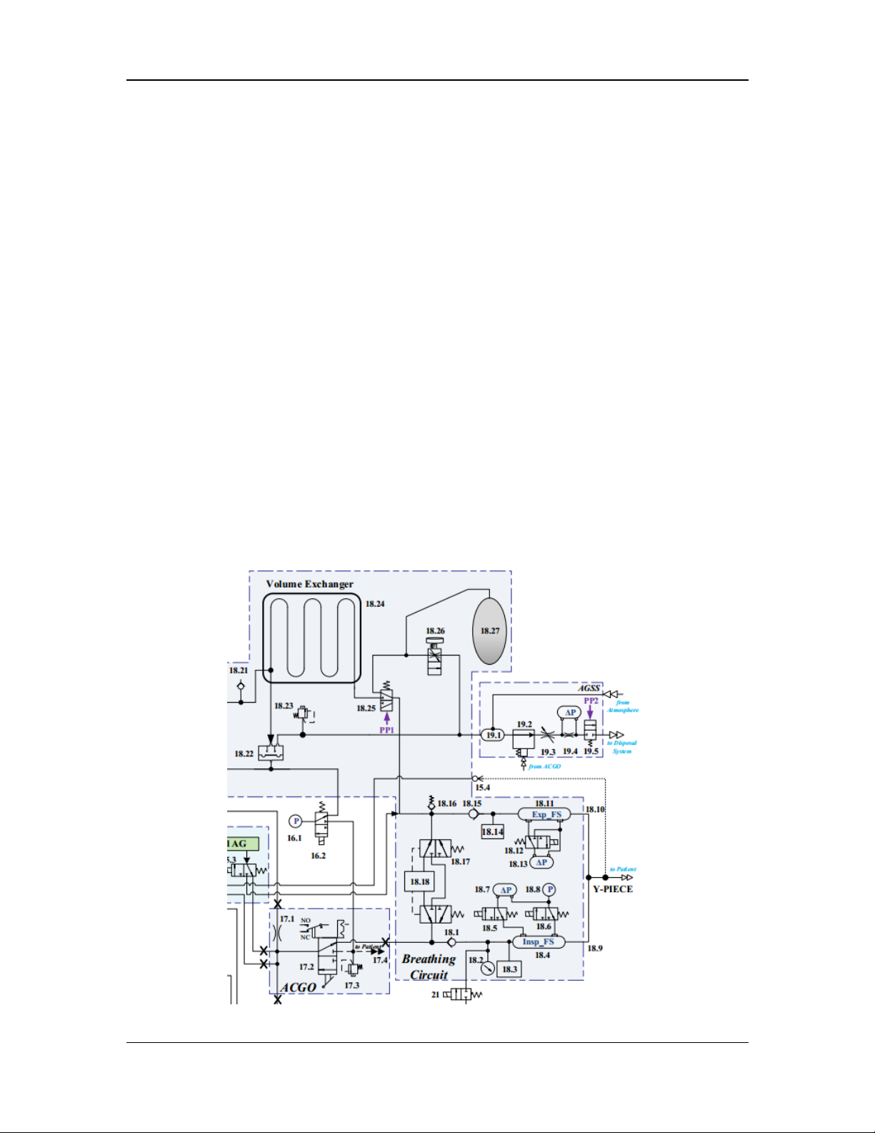
2.3.5 Breathing Subsystem
The breathing subsystem is an inspiratory and expiratory channel through which the gas flows
under breathing pressure between the fresh gas inlet, the patient connection port, and the exhaust
valve/port. The breathing subsystem provides a closed loop for the anesthetic gas, making the
expired gas from the patient enter the patient's breathing circuit again after the CO2 in the gas is
absorbed, to control the patient's anesthesia depth. It consists of the patient circuit assembly,
airway pressure gauge assembly (18.2), auto/manual switch assembly, auto/manual drive valve
assembly (18.25), APL valve assembly (18.26), absorber canister (18.18), bypass assembly
(18.17), volume exchanger assembly (18.24), O2 cell calibration valve assembly, and drive gas
assembly. The pneumatic diagram of the breathing subsystem is shown below.
In auto mode, during inspiration, the drive gas drives the mixed gas in the volume exchanger
(18.24) to flow through the auto/manual valve (18.25) and absorber canister (18.18) and then mix
with the fresh gas. The mixed gas flows through the inspiratory check valve (18.1) and
inspiratory flow sensor (18.4), and is pressurized into the patient's lungs through the breathing
tube connected to the inspiratory port (18.9). The CO2 in the mixed gas is absorbed by the
absorbent (such as sodalime) in the absorber canister when passing through the absorber canister,
to prevent the CO2 from being inspired by the patient. During expiration, the mixed gas in the
patient's lungs flows through the breathing tube connected to the expiratory port (18.10), passes
through the expiratory flow sensor (18.11), expiratory check valve (18.15), and auto/manual
valve (18.25), and enters the volume exchanger (18.24) again, to pressurize the drive gas from the
last inspiratory cycle out of the volume exchanger (18.24) and drain it through the expiratory
valve (18.22), so as to complete a breathing cycle.
In manual mode, the auto/manual valve (18.25) is driven by the pilot valve to switch to the
manual state. In this case, you can control the patient's breathing by pressing the manual bag, and
the excess gas escapes through the APL valve (18.26).
Figure 25 Schematic diagram of the breathing subsystem
2-72
 Loading...