

Page 1

WATO EX-55Pro/65Pro
Anesthesia Machine
Service Manual
Page 2

Page 3

Intellectual Property Statement
SHENZHEN MINDRAY BIO-MEDICAL ELECTRONICS CO., LTD. (hereinafter called
Mindray) owns the intellectual property rights to this product and this manual. This manual may
refer to information protected by copyrights or patents and does not convey any license under the
patent rights of Mindray, nor the rights of others. Mindray does not assume any liability arising
out of any infringements of patents or other rights of third parties.
Mindray intends to maintain the contents of this manual as confidential information. Disclosure of
the information in this manual in any manner whatsoever without the written permission of
Mindray is strictly forbidden. Release, amendment, reproduction, distribution, rent, adaption and
translation of this manual in any manner whatsoever without the written permission of Mindray is
strictly forbidden.
、 , and WATO are the registered trademarks or trademarks owned
by Mindray in China and other countries. All other trademarks that appear in this manual are used
only for editorial purposes without the intention of improperly using them. They are the property
of their respective owners.
Contents of this manual are subject to changes without prior notice.
Revision History
This manual has a revision number. This revision number changes whenever the manual is
updated due to software or technical specification change. Contents of this manual are subject to
change without prior notice. Revision 1.0 is the initial release of the document.
Rev
Release time: 2021-07
© Copyright 2016-2021 Shenzhen Mindray Bio
ision number: 5.0
-Medical Electronics Co., Ltd. All rights reserved.
I
Page 4

Preface
Manual Purpose
This manual provides detailed information about the assembling, dissembling, testing and
troubleshooting of the equipment to support effective troubleshooting and repair. It is not intended
to be a comprehensive, in-depth explanation of the product architecture or technical
implementation. Observance of the manual is a prerequisite for proper equipment maintenance and
prevents equipment damage and personal injury.
This manual is based on the maximum configuration. Therefore, some contents may not apply to
your monitor. If you have any question, please contact our Customer Service Department.
Intended Audience
This manual is geared for biomedical engineers, authorized technicians or service representatives
responsible for troubleshooting, repairing and maintaining the anesthesia machines.
Password
A password is required to access different modes within the anesthesia machine.
Manage Configuration: 789789
Factory maintenance: 558188
II
Page 5

Contents
1 Safety ......................................................................................................................................... 1-1
1.1 Safety Information .................................................................................................................. 1-1
1.2 Warnings ................................................................................................................................. 1-1
1.3 Cautions .................................................................................................................................. 1-2
1.4 Notes ....................................................................................................................................... 1-2
2 Theory of Operation ................................................................................................................ 2-1
2.1 Electrical Part .......................................................................................................................... 2-1
2.1.1 Outside Ports ...................................................................................................... 2-2
2.1.2 Electrical Theory ................................................................................................ 2-3
2.1.5 Display System ................................................................................................. 2-21
2.1.6 Control System ................................................................................................. 2-26
2.1.7 EFCS flowmeter system ................................................................................... 2-37
2.1.9 Others ............................................................................................................... 2-41
2.2 Pneumatic Part ...................................................................................................................... 2-45
2.2.1 Pneumatic Circuit Diagram .............................................................................. 2-45
2.2.2 Pneumatic Components and Symbles .............................................................. 2-46
2.2.3 Gas Supplies ..................................................................................................... 2-48
2.2.4 Anesthetic Gas Delivery System ...................................................................... 2-51
2.2.5 Breathing System ............................................................................................. 2-57
2.2.6 Pneumatically-Controlled Module of Anesthetic Ventilator ............................ 2-61
2.2.7 Anesthetic Gas Scavenging System ................................................................. 2-62
2.2.8 Breathing System Heater .................................................................................. 2-63
2.2.9 Ventilator Pneumatic - O2 Drive Gas ............................................................... 2-63
2.2.10 Drive Pressure - High Pressure Regulator (200 kPa, 29 psi) .......................... 2-64
2.2.11 Drive Gas Assembly ....................................................................................... 2-64
2.2.12 Negative Pressure Suction System ................................................................. 2-64
3 Installation Guide ..................................................................................................................... 3-1
3.1 Preparation .............................................................................................................................. 3-1
3.2 Assembly ................................................................................................................................. 3-1
3.2.1 Unpacking and Setup ......................................................................................... 3-2
3.2.2 Breathing System, Breathing System Accessories and Checkout Procedures . 3-17
3.2.3 AGSS Connections ........................................................................................... 3-17
3.2.4 Vaporizer .......................................................................................................... 3-18
3.2.5 Cylinder Installation ......................................................................................... 3-21
3.2.6 Patient Circuit and CO2 Absorbent .................................................................. 3-21
3.2.7 Monitoring Products Mounting and Electrical Connection (optional) ............. 3-22
3.2.8 Anesthesia Module Installation and Waste Gas Scavenging ............................ 3-22
3.2.9 Negative Pressure Suction ................................................................................ 3-22
1
Page 6

4 Testing ....................................................................................................................................... 4-1
4.1 System Inspection ................................................................................................................... 4-1
4.2 System Self- Test ..................................................................................................................... 4-2
4.3 Leak and Compliance Tests ..................................................................................................... 4-3
4.3.2 Manual Circuit Leak Test ................................................................................... 4-4
4.3.3 Troubleshooting—Leak Test .............................................................................. 4-5
4.4 Gas Supply Tests ..................................................................................................................... 4-5
4.4.1 O2 Pipeline Supply Test ..................................................................................... 4-5
4.4.2 N2O Pipeline Supply Test .................................................................................. 4-6
4.4.3 Air Pipeline Supply Test ..................................................................................... 4-6
4.5 Cylinder Supply Tests ............................................................................................................. 4-6
4.5.1 O2 Cylinder Supply Test .................................................................................... 4-6
4.5.2 N2O Cylinder Supply Test ................................................................................. 4-7
4.5.3 Air Cylinder Supply Test .................................................................................... 4-7
4.6 EFCS Accuracy Test ............................................................................................................... 4-7
4.7 BFCS Function Tests ............................................................................................................... 4-8
4.8 Flow Control System Tests ..................................................................................................... 4-9
4.8.1 Without O2 Sensor ............................................................................................. 4-9
4.8.2 With O2 Sensor ................................................................................................. 4-11
4.9 Vaporizer Test ........................................................................................................................ 4-12
4.9.1 Vaporizer Interlock Test ................................................................................... 4-12
4.9.2 Vaporizer Back Pressure Test ........................................................................... 4-12
4.9.3 Vaporizer Accuracy Test ................................................................................... 4-13
4.9.4 Vaporizer Leak Test .......................................................................................... 4-14
4.10 Other Functional Tests ........................................................................................................ 4-15
4.10.1 Drive Gas Switching Function Test ................................................................ 4-15
4.10.2 Auxiliary O2 Supply Flowmeter Accuracy Test ............................................. 4-15
4.10.3 O2 Flush Test ................................................................................................. 4-16
4.10.4 ACGO Function Tests .................................................................................... 4-17
4.10.5 AGSS Inspection ............................................................................................ 4-17
4.10.6 Negative Pressure Suction Inspection ............................................................ 4-19
4.11 Breathing Circuit Tests ........................................................................................................ 4-20
4.11.1 Check Valve Test ............................................................................................ 4-20
4.11.2 Bellows Test ................................................................................................... 4-21
4.11.3 Breathing System Leak Test in Manual Ventilation Mode ............................. 4-21
4.11.4 Breathing System Leak Test in Mechanical Ventilation Mode ....................... 4-23
4.11.5 APL Valve Test ............................................................................................... 4-27
4.11.6 O2 Sensor Related Tests ................................................................................. 4-27
4.11.7 Bypass Function Test ...................................................................................... 4-28
4.12 Alarm Tests .......................................................................................................................... 4-29
4.12.1 Prepare for Alarm Tests .................................................................................. 4-29
4.12.2 Test the O
Concentration Monitoring and Alarms ........................................ 4-30
2
4.12.3 Test the Low Minute Volume (MV) Alarm .................................................... 4-30
4.12.4 Test the Apnea Alarm ..................................................................................... 4-30
2
Page 7

4.12.5 Test the Sustained Airway Pressure Alarm ..................................................... 4-30
4.12.6 Test the High Paw Alarm ................................................................................ 4-31
4.12.7 Test the Low Paw Alarm ................................................................................ 4-31
4.12.8 Breathing System Not Mounted Alarm Test .................................................. 4-31
4.12.9 CO2 Absorbent Canister Alarm Test .............................................................. 4-31
4.12.10 O2 Supply Failure Alarm Test ...................................................................... 4-32
4.12.11 Drive Gas Pressure Low Alarm Test ............................................................ 4-32
4.12.12 Power Failure Test ........................................................................................ 4-32
4.13 System Ventilation Performance Tests ................................................................................ 4-32
4.13.1 Standby Mode Ventilation Test....................................................................... 4-32
4.13.2 Manual Mode Ventilation Test ....................................................................... 4-33
4.13.3 VCV Adult Ventilation Mode Test ................................................................. 4-33
4.13.4 VCV Child Ventilation Mode Test ................................................................. 4-34
4.13.5 Air Way Disconnection Alarm Test ................................................................ 4-34
4.13.6 PCV Adult Ventilation Mode Test .................................................................. 4-35
4.13.7 PS Ventilation Mode Test ............................................................................... 4-35
4.14 State Test of Sensors ........................................................................................................... 4-36
4.14.1 Checking the Sensor Zero Point ..................................................................... 4-36
4.14.2 Constant Flow Test (Checking the Flow Sensor Accuracy) ........................... 4-37
4.14.3 Constant Pressure Test (Checking the Pressure Sensor Accuracy) ................ 4-41
4.15 Electrical Safety Inspection ................................................................................................. 4-46
4.15.1 Auxiliary Electrical Outlet Test ...................................................................... 4-46
4.15.2 Top Light, Auxiliary Gas Supply and Total Flowmeter Backlight Test .......... 4-46
4.15.3 Electrical Safety Inspection Test .................................................................... 4-47
4.15.4 Electrical Safety Inspection Form .................................................................. 4-47
5 Factory Maintenance Menu .................................................................................................... 5-1
5.1 Calibration ............................................................................................................................... 5-1
5.2 Data Monitors ......................................................................................................................... 5-2
5.3 Valves Diagnostic Test Tools ................................................................................................. 5-13
5.3.1 Valves Test ........................................................................................................ 5-13
5.3.2 Insp. Valve Test ................................................................................................ 5-15
5.3.3 PEEP Valve Test ............................................................................................... 5-17
5.3.4 Safety Valve Test .............................................................................................. 5-17
5.4 Review Logs ......................................................................................................................... 5-17
5.5 System Info ........................................................................................................................... 5-18
5.6 Demo Mode........................................................................................................................... 5-19
5.7 Restore All Default ................................................................................................................ 5-19
5.8 Factory Setup ........................................................................................................................ 5-20
5.9 Function Activation ............................................................................................................... 5-21
5.10 Drive Gas ............................................................................................................................ 5-21
5.11 Drive Gas Auto Switch ........................................................................................................ 5-21
5.12 Air Pressure Switch Sensor ................................................................................................. 5-21
5.13 Flowmeter Standard ............................................................................................................ 5-21
3
Page 8

5.14 Flowmeter Pipeline ............................................................................................................. 5-21
5.15 ACGO ................................................................................................................................. 5-22
5.16 Module Rack ....................................................................................................................... 5-22
5.17 AG Module .......................................................................................................................... 5-22
5.18 BIS Module ......................................................................................................................... 5-22
5.19 CO2 Module ........................................................................................................................ 5-22
6 Device Maintenance ................................................................................................................. 6-1
6.1 Maintenance Overview ........................................................................................................... 6-1
6.2 Maintenance Period ................................................................................................................. 6-1
6.3 System Check .......................................................................................................................... 6-2
6.4 Maintenance Package Parts ..................................................................................................... 6-2
6.4.1 One-year Replaceable Parts ............................................................................... 6-2
6.5 Other Materials Need to be Checked and Replaced .............................................................. 6-16
6.5.1 Maintenance and Replacing of Battery ............................................................ 6-16
6.6 Tests after Maintenance ......................................................................................................... 6-16
6.6.1 Check the Mechanical Ventilation Mode ......................................................... 6-18
6.6.2 Breathing System Leak Test in Mechanical Ventilation Mode ........................ 6-20
6.6.3 Breathing System Leak Test in Manual Ventilation Mode ............................... 6-20
6.6.4 Check the Sensor Zero Point ............................................................................ 6-21
6.6.5 Check the Flow Sensor Accuracy ..................................................................... 6-22
6.6.6 Check the Pressure Sensor Accuracy ............................................................... 6-23
6.6.7 Check the Electronic Flowmeter Accuracy ...................................................... 6-24
7 System Calibration ................................................................................................................... 7-1
7.1 Overview ................................................................................................................................. 7-1
7.2 Precautions .............................................................................................................................. 7-1
7.2.1 Warnings ............................................................................................................. 7-1
7.2.2 Cautions ............................................................................................................. 7-2
7.2.3 Notes .................................................................................................................. 7-2
7.3 System Calibration .................................................................................................................. 7-3
7.3.1 Flow Calibration (User) ..................................................................................... 7-4
7.3.2 Flow calibration (Service) .................................................................................. 7-9
7.3.3 Pressure Calibration (Service) .......................................................................... 7-27
7.3.4 Pressure and Flow Zeroing (Service) ............................................................... 7-39
7.3.5 EFCS Flowmeter Zeroing (User) ..................................................................... 7-41
7.3.6 O2 Sensor Calibration ...................................................................................... 7-45
7.3.7 Total Flow Sensor Calibration (factory) ........................................................... 7-51
7.3.8 CO2 Calibration (factory) ................................................................................ 7-54
7.3.9 AG Calibration (factory) .................................................................................. 7-56
7.3.10 O2 Module Calibration (factory) .................................................................... 7-57
8 Troubleshooting ........................................................................................................................ 8-1
8.1 Troubleshooting Guide ............................................................................................................ 8-1
4
Page 9

8.1.1 Fault Determination ........................................................................................... 8-1
8.1.2 Avoiding Short Circuit of Component Leads ..................................................... 8-1
8.1.3 Using Appropriate Tools .................................................................................... 8-1
8.1.4 Cleanup of the Maintenance Area ...................................................................... 8-2
8.2 Technical Alarms ..................................................................................................................... 8-2
8.2.1 Startup Alarm Messages ..................................................................................... 8-2
8.2.2 CPU Board Runtime Alarms .............................................................................. 8-7
8.2.3 Power Board Runtime Alarms ............................................................................ 8-8
8.2.4 Electronic Flowmeter Board Runtime Alarms ................................................. 8-10
8.2.5 VCM Board Runtime Alarms ........................................................................... 8-12
8.2.6 External AG Module Runtime Alarms ............................................................. 8-17
8.2.7 BIS Module Runtime Alarms ........................................................................... 8-19
8.2.8 CO2 Module Runtime Alarms .......................................................................... 8-23
8.2.9 Mainstream CO
8.2.10 Microstream CO
module: ................................................................................. 8-24
2
module: ............................................................................. 8-25
2
8.3 Leak and Compliance Tests ................................................................................................... 8-26
8.3.1 Automatic Circuit Leak and Compliance Test .................................................. 8-26
8.3.2 Manual Circuit Leak Test ................................................................................. 8-27
8.3.3 Troubleshooting—Leak Test ............................................................................ 8-29
8.4 Airway System Failure .......................................................................................................... 8-29
8.4.1 Onsite Maintenance Tools ................................................................................ 8-30
8.4.2 Effectiveness Test for the Pipeline Pressure Gauge and Correction of the
Regulator ................................................................................................................... 8-40
8.4.3 AG Transmission System ................................................................................. 8-47
8.4.4 Breathing System ............................................................................................. 8-56
8.4.5 Tidal Volume .................................................................................................... 8-71
8.5 Sensor and Valve Faults ........................................................................................................ 8-73
8.5.1 Mapping Between Menu Items on the Valve Diagnosis Tool Interface and
Airways ..................................................................................................................... 8-74
8.5.2 Mapping Between Menu Items on the Valve Diagnosis Tool Interface and
Hardware Components .............................................................................................. 8-75
8.5.3 Preparations Before Using the Valve Diagnosis Tool ....................................... 8-76
8.5.4 Diagnosing Zero Point Exceptions of Sensors ................................................. 8-76
8.5.5 Diagnosing Flow Data Exceptions of Sensors ................................................. 8-76
8.5.6 Diagnosing Pressure Data Exceptions of Sensors ............................................ 8-78
8.5.7 Diagnosing Inspiratory valve Exceptions ......................................................... 8-79
8.5.8 Diagnosing PEEP Safety Valve Exceptions ..................................................... 8-80
8.5.9 Diagnosing PEEP Proportional Valve Exceptions ............................................ 8-80
8.6 Gas Source and Drive Gas Faults .......................................................................................... 8-81
8.7 Hardware and Electrical Faults ............................................................................................. 8-90
8.8 Software Upgrade and Software Configuration Activation .................................................. 8-93
8.8.1 Common Software Upgrade Problems and Solutions ...................................... 8-97
8.8.2 Software Function Activation ........................................................................... 8-98
5
Page 10

9 Repair and Disassembly .......................................................................................................... 9-1
9.1 Prepare for Disassembly ......................................................................................................... 9-2
9.1.1 Tools ................................................................................................................... 9-2
9.1.2 Preparations ........................................................................................................ 9-2
9.1.3 Release Pressure ................................................................................................. 9-3
9.2 Disassemble Assemblies ......................................................................................................... 9-3
9.2.1 Remove Top Cover Assembly and Top Plate Assembly .................................... 9-3
9.2.2 Remove Speaker ................................................................................................. 9-4
9.2.3 Remove Top Light Board and Switch ................................................................ 9-5
9.2.4 Remove Service Door and Rear Cover Plate ..................................................... 9-5
9.2.5 Remove Cart Rear Cover Plate Assembly .......................................................... 9-6
9.2.6 Remove Module Rack Box Assembly ................................................................ 9-7
9.2.7 Remove Module Rack Fan ................................................................................. 9-7
9.2.8 Remove Display Assembly ................................................................................ 9-8
9.2.9 Remove Key Control Board ............................................................................... 9-9
9.2.10 Remove Work Surface Light Board ............................................................... 9-10
9.2.11 Remove the Alarm Lamp Board ...................................................................... 9-11
9.2.12 Remove Encoder Board and Encoder ............................................................. 9-11
9.2.13 Remove Display and Touch Screen ................................................................ 9-12
9.2.14 Remove Hardware Box Assembly ................................................................. 9-13
9.2.15 Replace Fuse .................................................................................................. 9-16
9.2.16 Replace Battery .............................................................................................. 9-16
9.2.17 Remove EFCS flowmeter ............................................................................... 9-17
9.2.18 Remove EFCS Flowmeter Board ................................................................... 9-18
9.2.19 Remove Flowmeters ....................................................................................... 9-19
9.2.20 Remove Proportional Valve, Three-Way Valve and Two-Way Valve ............. 9-20
9.2.21 Remove Vaporizer Manifold .......................................................................... 9-21
9.2.22 Remove Gas Source Inlet Port Assembly ....................................................... 9-21
9.2.23 Remove Backup Gas Source Inlet Port Assembly ......................................... 9-23
9.2.24 Remove Backup Cylinder Bracket ................................................................. 9-24
9.2.25 Remove Cover Plate of Work Surface ............................................................ 9-25
9.2.26 Remove Exhalation Valve Assembly ............................................................. 9-27
9.2.27 Remove ACGO Assembly .............................................................................. 9-27
9.2.28 Remove Gas Reservoir Assembly .................................................................. 9-28
9.2.29 Remove O2 Flush Assembly .......................................................................... 9-28
9.2.30 Remove High-pressure Gauge Assembly ....................................................... 9-29
9.2.31 Remove Gas Supply Pressure Gauge Assembly ............................................ 9-30
9.2.32 Remove Negative Pressure Control Panel Assembly ..................................... 9-31
9.2.33 Remove Backup O2 Flowmeter Assembly .................................................... 9-31
9.2.34 Remove System Switch Assembly ................................................................. 9-32
9.2.35 Remove Indicator Light Board ....................................................................... 9-32
9.2.36 Remove Drive Gas Switching Valve .............................................................. 9-33
9.2.37 Remove Power Cable ..................................................................................... 9-33
9.2.38 Remove Drawer ............................................................................................. 9-34
6
Page 11

9.2.39 Remove Air Compressor ................................................................................ 9-35
9.2.40 Remove Cart Slide ......................................................................................... 9-36
9.2.41 Remove Lock of Drawers .............................................................................. 9-36
9.3 Disassemble Breathing System (not compatible with Pre-Pak) ............................................ 9-38
9.3.1 Remove O2 Sensor ........................................................................................... 9-38
9.3.2 Remove Breathing Tubes ................................................................................. 9-39
9.3.3 Remove Flow Sensor ....................................................................................... 9-41
9.3.4 Remove Manual Bag ........................................................................................ 9-42
9.3.5 Remove Bellows Assembly .............................................................................. 9-42
9.3.6 Remove Pop-off Valve Assembly ..................................................................... 9-43
9.3.7 Remove Expiratory Check Valve Assembly ..................................................... 9-44
9.3.8 Remove Inspiratory Check Valve Assembly .................................................... 9-45
9.3.9 Remove CO2 Absorbent Canister .................................................................... 9-46
9.3.10 Remove Water Collection Cup ....................................................................... 9-47
9.3.11 Remove Airway Pressure Gauge .................................................................... 9-48
9.3.12 Remove Bag Arm ........................................................................................... 9-48
9.3.13 Remove Breathing System ............................................................................. 9-49
9.3.14 Remove CO2 Absorbent Canister Connection Block Assembly .................... 9-50
9.3.15 Remove Back Upper Cover and Back Lower Cover Assemblies .................. 9-52
9.3.16 Remove Front Upper Cover ........................................................................... 9-53
9.3.17 Remove Median Plate Assembly .................................................................... 9-54
9.3.18 Remove Lower Cover Assembly .................................................................... 9-55
9.3.19 Remove Bag/vent Switch Assembly .............................................................. 9-55
9.3.20 Remove APL Valve Assembly ........................................................................ 9-57
9.4 Disassemble the Breathing System (compatible with Pre-Pak) ............................................ 9-58
9.4.1 Remove O2 Sensor ........................................................................................... 9-58
9.4.2 Remove Breathing Tubes ................................................................................. 9-59
9.4.3 Remove Flow Sensor ....................................................................................... 9-60
9.4.4 Remove Manual Bag ........................................................................................ 9-61
9.4.5 Remove the Absorbent Canister ....................................................................... 9-61
9.4.6 Remove CO2 Bypass Assembly ....................................................................... 9-62
9.4.7 Remove Drain Valve ........................................................................................ 9-62
9.4.8 Remove Bypass Valve and the Trigger Board .................................................. 9-63
9.4.9 Remove Patient Circle Assembly ..................................................................... 9-65
9.4.10 Remove Bellows Assembly ............................................................................ 9-65
9.4.11 Remove Pop-off Valve Assembly ................................................................... 9-66
9.4.12 Remove Expiratory/Inspiratory Check Valve Assemblies .............................. 9-67
9.4.13 Remove Water Collection Cup ....................................................................... 9-67
9.4.14 Remove Airway Pressure Gauge .................................................................... 9-68
9.4.15 Remove Bag Arm ........................................................................................... 9-68
9.4.16 Remove the Back Upper Cover and Back Lower Cover Assemblies ............. 9-69
9.4.17 Remove the Front Upper Cover, Median Plate and Front Lower Cover
Assemblies ................................................................................................................ 9-70
9.4.18 Remove Automatic/Manual Ventilation Switch Assembly ............................ 9-72
7
Page 12

9.4.19 Remove APL Valve Assembly ........................................................................ 9-74
9.5 Electrical and Pneumatic Connections .................................................................................. 9-75
9.5.1 Electrical Connections...................................................................................... 9-75
9.5.2 Pneumatic Connections .................................................................................... 9-79
10 Replacement Parts ............................................................................................................... 10-1
10.1 Introduction ......................................................................................................................... 10-1
10.2 Ordering Replaceable Parts ................................................................................................. 10-1
10.3 Diagrams and Tables ........................................................................................................... 10-2
10.3.1 Upper Half ...................................................................................................... 10-6
10.3.2 Hardware Box ................................................................................................ 10-9
10.3.3 Work Surface ................................................................................................ 10-13
10.3.4 WATO EX-55 Pro/65 Pro Auxiliary O2 Supply Flowmeter Assembly ........ 10-16
10.3.5 WATO EX-55 Pro/65 Pro Cart Assembly .................................................... 10-17
10.3.6 WATO EX-55 Pro/65 Pro Pre-pak Circuit Bracket Assembly ...................... 10-19
10.3.7 Breathing Circuit Adapter Block Assembly ................................................. 10-21
10.3.8 Main Body of the Breathing Circuit ............................................................. 10-22
10.3.9 CO2 Absorber Canister Assembly ................................................................ 10-23
10.3.10 Expiratory Check Valve and Inspiratory Check Valve ............................... 10-27
10.3.11 O2 Cell Assembly ....................................................................................... 10-27
10.3.12 WATO EX-55 Pro/65 Pro Display Assembly ............................................. 10-28
10.3.13 WATO EX-55 Pro/65 Pro Backup flowmeter assembly ............................. 10-29
10.3.14 Base Assembly ........................................................................................... 10-30
10.3.15 Tubes .......................................................................................................... 10-33
10.3.16 O-ring ......................................................................................................... 10-34
A Test Items .................................................................................
A.
Post-Installation Test Items............................................................................................. A-1
1
A.
Post-Maintenance Test Items ......................................................................................... A-2
2
A.
3
Post-Repair Test Items.................................................................................................... A-3
........................................ A-1
8
Page 13
1 Safety
1.1 Safety Information
Please read and adhere to all warnings, cautions and notes listed here and in the appropriate areas
throughout this manual.
WARNING
Indicates a potential hazard or unsafe practice that, if not avoided, could result in
death or serious injury.
CAUTION
Indicates a potential hazard or unsafe practice that, if not avoided, could result in
minor personal injury or product/property damage.
NOTE
Provides application tips or other useful information to ensure that you get the
most from your product.
1.2 Warnings
WARNING
Whenever using anesthetic gases, nitrous oxide, oxygen, or any hospital gas always
follow the appropriate agent evacuation/collection procedures. Use the hospital gas
evacuation system.
Use only an approved lubricant on any O-ring in contact with oxygen. Krytox® is
the recommended oxygen service lubricant.
For continued protection against fire hazard, replace all fuses with the specified
type and rating.
In order to prevent an electric shock, the machine (protection class I) may only be
connected to a correctly grounded mains connection (socket outlet with grounding
contact).
Remove all accessory equipment from the shelf before moving the anesthesia
machine over bumps or on any inclined surface. Heavy top loading can cause the
machine to tip over causing injury.
Possible explosion hazard. Do not operate machine near flammable anesthetic
agents or other flammable substances. Do not use flammable anesthetic agents (i.e.
ether or cyclopropane.)
The use of anti-static or electrically conductive respiration tubes, when utilizing
high frequency electric surgery equipment, may cause burns and is therefore not
recommended in any application of this machine.
Possible electric shock hazard. The machine may only be opened by authorized
service personnel.
Avoid exposure to respiratory gases by always directing the fresh gas flow from the
fresh gas outlet to the waste gas scavenger.
1-1
Page 14

1.3 Cautions
CAUTION
This device uses high pressure compressed gas. When attaching or disconnecting
backup gas cylinders, always turn the cylinder valves slowly. Use the flow meters to
bleed down the pressure, watching the cylinder gauge indicate the depleting
cylinder pressure, before disconnecting the cylinder from the yoke. Always open
and close cylinder valves fully.
This device operates using compressed gas at high pressures from the hospital
central supply. When connecting gas supply lines attach the hose connection to the
machine before connecting the quick disconnect fitting to the hospital source.
Disconnect the supply hose from the hospital source connection prior to
disconnecting it from the gas connection fittings.
Refer to the 6.2Maintenance Period for assistance when performing scheduled
periodic maintenance.
Do not leave gas cylinder valves open if the pipeline supply is in use and the system
master switch is turned to 'ON'. If used simultaneously, cylinder supplies could be
depleted, leaving an insufficient reserve supply in the event of pipeline failure.
Use cleaning agent sparingly. Excess fluid could enter the machine, causing
damage.
This machine must only be operated by trained, skilled medical staff.
Perform the electrical safety inspection as the last step after completing a repair or
after routine maintenance. Perform this inspection with all covers, panels, and
screws installed.
After changing the CO2 absorbent, carry out a system leak test.
Only Selectatec™ compatible vaporizers with Interlock-System may be used with
the A5 unit.
After each exchange of a vaporizer, carry out a system Leak test.
Do not clean the machine while it is on and/or plugged in.
Pressing “cancel” at any time during the procedure will cancel the session's
settings and reload the previously-stored calibration coefficients.
Depleted soda lime changes color. Replace the soda lime if approximately 2/3 of the
absorber content is discolored. CO2 absorbent can be safely changed without
stopping mechanical ventilation.
This equipment contains parts which are easily damaged due to electrostatic
discharge (ESD). Follow ESD prevention program when touching, taking out, or
inserting parts or components.
1.4 Notes
NOTE
Unauthorized servicing may void the remainder of the warranty. Check with the
factory or with a local authorized distributor to determine the warranty status of a
particular instrument.
1-2
Page 15

2 Theory of Operation
2.1 Electrical Part
The hardware system of WATO EX-55/65 includes: mother board, power sub-system, main unit
sub-system, display sub-system, gas parsmeters module sub-system, electronic flowmeter
sub-system, pneumatic accessories, and others. The introductions of the modules are as follows:
1. Mother board: connects to the related parts of cards and hardwares, and transfers related
signals to corresponding cards and components.
2. Power sub-system: includes power board, battery adapter board, lithium battery, AC
input, auxiliary electrical outlet, etc. It supplies power to anesthesia machine and its
external equipments.
3. Main unit sub-system: includes main control board and monitoring module. Main
control board realizes the human-machine interaction function of the anesthesia machine
and the data exchange with monitoring module and electronic flowmeter sub-system,
and it extends with USB, network port, RS-232 series port, VGA port, calibration port,
etc. Monitoring module controls the parameters of the anesthesia machine and realizes
monitoring function, and it includes ventilation control board and ventilation protection
board.
4. Display sub-system: includes key control board, encoder board (main encoder), EFCS
flowmeter encoder board, alarm light board, screen, touchscreen, touch key board, etc.
Key control board realizes the functions of EFCS flowmeter encoder, encoder
recognition, touchscreen recognition, touch key recognition, backlight control, etc, and it
also transfers the signal of alarm light controlled by main control board and the
backlight enable signal, and send data to main control board through series port.
5. EFCS flowmeter sub-system: includes EFCS flowmeter control board, flow sensor
board, proportional valve, three-way valve, NC valve, and NO valve. EFCS flowmeter
control board monitors and controls the flow of fresh gas in real time, and exchanges
data with master through series port.
6. Gas parsmeters module sub-system: includes infrared backlight board, parameter
module, fan of module rack, and interior AG module.
7. Except the modules and cards above, the hardware system of WATO EX-65/55 also
includes several components related to hardware, for example, valve, position switch,
heater, speaker, heat-sink fan, etc.
2-1
Page 16
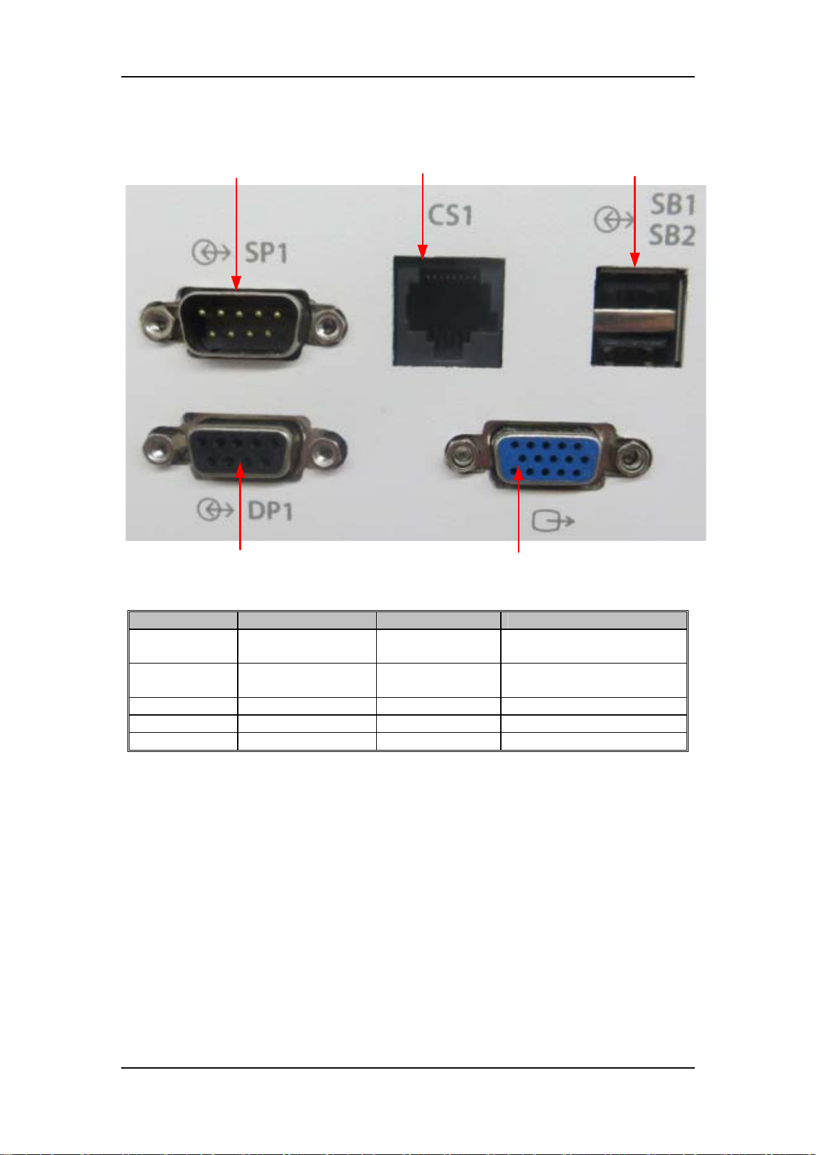
2.1.1 Outside Ports
Series port for
interconnection of
devices
Network port
USB port
Calibration port
VGA port
Name Located card Property Function
Network port Main control board RJ-45
USB port Main control board
Calibration port Mother board DB-9, female connects to calibration device
RS232 port Main control board DB-9, male connects to patient monitor
VGA port Mother board DB-15, female connects to external display
Dual A type
receptacle
online upgrade;
data outport
data outport;
connects to mouse
2-2
Page 17
2.1.2 Electrical Theory
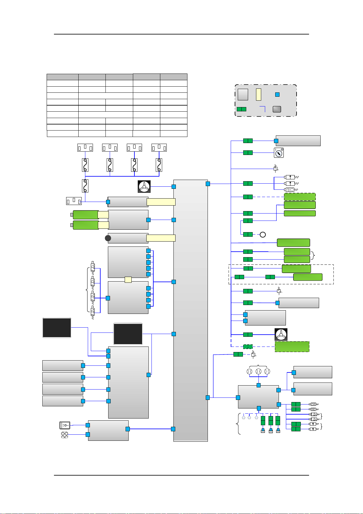
2.1.2.1 Theory Diagram
Standards of power
Domestic standard M39-000207--- 009-005461-XX
European standard M39-000208--- 009-005324-XX
American standard 009-000067-XX
British standard 008-000027-00 009-000068-XX
Indian standard 008-000060-00 009-000068-XX
B specification 220V 009-000127-XX
Brazil standard 008-000229-00 009-005325-XX
Australian standard M39-000207--- 009-005461-XX
Big South African
standard
Auxiliary
electrical outlet
008-000487-00 009-003179-XX
Auxiliary
electrical outlet
Auxiliary
electrical outlet
C1 C1 C1C1
C1
electrical outlet
Auxiliary
Total Fuse
010-000081-00
010-000081-00
010-000081-00
010-000081-00
010-000081-00
010-000081-00
010-000081-00
010-000081-00
010-000081-00
electrical outlet
Auxiliary
Fuse of auxiliary
electrical outlet
M07-00131F---
M07-00131F--M07-00131F--M07-00131F--M07-00131F--M07-00131F--M07-00131F--M07-00131F--M07-00131F---
Card
Cord-to-
cord
connection
Board-to-
board
receptacle
C19
C20
Cord
Board-to-
cord
receptacle
Hardware
purchased
materials
Indicator light board
J1
B12
System switch
AC input
Touchscreen
E5
EFCS encoder board
B7
Alarm light board
B8
Encoder board
B9
Auxiliary Lighting
board
B10
Third gear
mechanical
switch
Speaker
E15
Threeway valve
J1
J1
J1
J1
C25
Fuse
Total
Fuse
C4/C5
Battery
E2
Battery
E3
Button battery
E4
C13
C14
C15
C16
J2
J3
Fuse
C2/C3
J2
Battery adapter
J1
Main control board
B1
protection board
C7
J6
C9
J3
J5
J7
J2
Key control board
J4
J6
0625 top light board
B17
Fan of
module rack
E1
Power board
B1
board
B2
B3
Ventilation
B4
J22
2*22
J20
Ventilation
control board
B5
LCD
E9
B6
J1
Fuse
J15
J10
J12
Fuse
C17
B11
J2
C23
C24
C27
C30
J4
Infrared
communication board
J2
C32
C34
Air pressure switch
at gas source inlet
J7
2*25
J3J1
J3
J3
J2
J4
J8
J7
J1
J5
J10
C6
J9
3*32
J11
C8
J1
Mother board
C11/C12
J3
Pressure switch of pneumatic block
C21
C22
Manual/Auto switch
O2 sensor
O2
E12
Limit switch of
manual ACGO
Heating wire of
C27
Limit switch Of
absorbent canister
C28
Different configurations
O2 pressure switch
at gas source inlet
C31
Flowmeter backlight board
J1
B16
Anesthetic gas
calculation module
(Interior Agmodule)
Inspiration valve
PEEP valve
Safety valve
Drive gas selector
valve
Circuit in-place
switch
Thermistor Of
heater
heater
Limit switch Of
absorbent canister
B15
Fan of
module rack
E14
E13
Without L arm
With
L arm
Flow sensor
Backup flowmeter
J1
J1
J4
C18
C33
J1
J6
Electronic pressure
sensor
C37
J8
EFCS control board
B13
J13
C41
E16×3
C42×3
B19×3
C36
J5
C35
J7
backlight board
B18
Backup flowmeter key
board
J1
B14
C40
NC valve
C39
NO valve
C38
C38
Threeway valve
Proportio
nal valve
2-3
Page 18
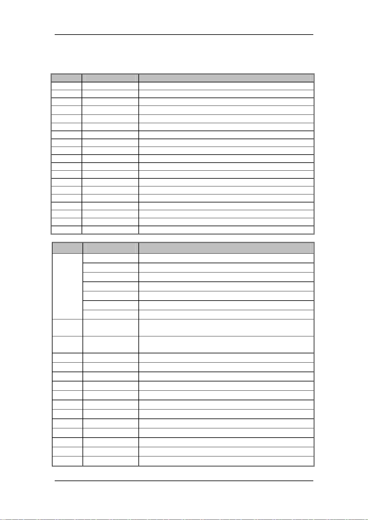
2.1.2.2 Hardware Components List
Cards list
No. P/N Description
B1 051-001261-00 0631 Power board
B2 051-000768-00 0623 Battery adapter board PCBA
B3 051-001863-00 0625 Main control board PCBA
B4 051-001996-00 0625 Ventilation protection board PCBA(Norgren)
B5
B6 051-002623-00 0625 Key control board PCBA
B7 051-001260-00 0632 Encoder board PCBA
B8 051-000415-00 0631 Alarm light board PCBA
B9 0010-30-43089 Copper spool encoder board
B10 051-001867-00 0625 Auxiliary lighting board PCBA
B11 051-002637-00 0627 Mother board PCBA
B12 051-001934-00 0625 Indicator light board PCBA
B13 051-002622-00 0627 EFCS flowmeter control board PCBA
B14 051-002581-00 0627 Standby flowmeter keyboard
B15 051-001256-00 0632 Total flowmeter backlight board PCBA
B16 051-000259-00 0621 Infrared communication board PCBA
B17 051-001866-00 0625 Top light board PCBA
B18 051-001256-00 0632 Total flowmeter backlight board PCBA
B19 051-002521-00 VT70 gas supply inlet pressure sensor board PCBA
Cords list
No. P/N Description
C1
C2 009-004703-00
C3 009-005323-00
C4 009-004704-00 0625 AC mains inlet cord
C5 009-005462-00 0625 AC mains inlet cord (without auxiliary electrical outlet)
C6 009-004705-00 0625 Battery adapter board connection line
C7 009-002592-00 0631 Three-way valve connection line (ACGO)
C8 009-004706-00 0625 Monitoring module connection line
C9 009-006899-00 0627 Screen backlight drive line
C11 009-006893-00 0627 Display assembly data line
C13 009-006900-00 0627 Alarm light board connection line
C14 009-006898-00 0627 Encoder board connection line
C15 009-006897-00 0627 Auxiliary lighting board connection line
C16 009-007235-00 0627 Pneumatic assembly connection line
C17 009-006893-00 0627 Display assembly data line
051‐003167‐00
009-005461-00 0625 Domestic standard connection line
009-005324-00 0625 European standard connection line
009-000067-00 American standard receptacle and connection line
009-000068-00 British standard connection line
009-000127-00 B specification 220V receptacle and connection line
009-005325-00 0625 Brazilian standard connection line
009-003179-00 0623 Big South African connection line
0625 Ventilation control board PCBA
0625 auxiliary electrical outlet connection line (Domestic
standard)
0625 auxiliary electrical outlet connection line (South African
standard)
2-4
Page 19
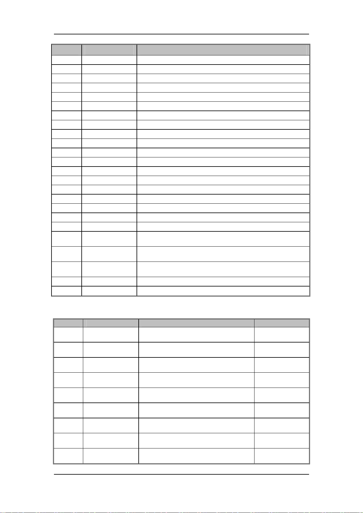
No. P/N Description
C18 009-004711-00 0627 Top light board connection line
C19 009-000977-00 0631 Indicator light connection line
C20 009-001776-00 0631 System switch line
C21 009-000066-00 NORGER pneumatic block connection line
C22 009-004713-00 0625 Drive gas selector valve connection line
C23 0621-20-78593 Switch (inside circuit) connection line
C24 0601-21-78956 2Pin female socket integrative object
C25 009-005644-00 0625 lighting board switch line
C26 0621-20-78648 three-way valve assembly connection line of flowmeter
C27 009-001491-00 0623 CO2absorbent canister connection line
C28 009-000987-00 0631absorbent canister switch line
C30 0621-20-69588 O2 pressure switch line at gas source inlet
C31 009-002931-00 0632 Total flowmeter backlight board connection line
C32 009-004715-00 0625 Interior AG module connection line
C33 009-006894-00 0627 EFCS flowmeter connection line
C34 0621-20-69588 O2 pressure switch connecting cable at gas supply inlet
C35 009-006896-00 0627 Flowmeter valve connection line
C36 009-006901-00 0627 BFCS keyboard connection line
C37 009-006895-00 0627 Flow sensor connecting cable
C38 009-007236-00
C39 009-007237-00
C40 009-007238-00
0627 Connecting cable of the proportional valve for the EFCS
flowmeter (with valve)
0627 Connecting cable of the NO valve for the EFCS flowmeter
(with valve)
0627 Connecting cable of the NC valve for the EFCS flowmeter
(with valve)
C41 009-005916-00 0635 Connecting cable of the pressure sensor for the gas supply
C42
009-008630-00
0635 pressure cable for pipeline gas supply
Other Parts List
No. P/N Description Note
E1 024-000125-00
E2 022-000008-00
E3 022-000008-00
E4 M05-010R03---
E5 021-000287-00
E9 021-000287-00
E12 0611-10-45654
E13 024-000428-00
E14 024-000407-00
FAN 12V 60*60*25mm 22.9CFM 36.5dB
380mm
Lithium battery, Li-ion11.1V4500mAh
LI23S002A
Lithium battery, Li-ion11.1V4500mAh
LI23S002A
Button battery, Lithium 3V35mAh
D12.5*2.0
Touchscreen, resistance-type, 15″
five-line
Touchscreen, resistance-type, 15″
five-line
Sensor Oxygen (O2 sensor)
MedicelMOX-2
Heater, silica gel, 16V46.6W, sensor with
metal sheet part
FAN, 12V, 40*40*20mm, 6.3CFM 18dB,
Ffeedback, special terminal
Module rack fan
/
/
used on main
control board
/
/
/
Circuit heater
Module rack fan
2-5
Page 20
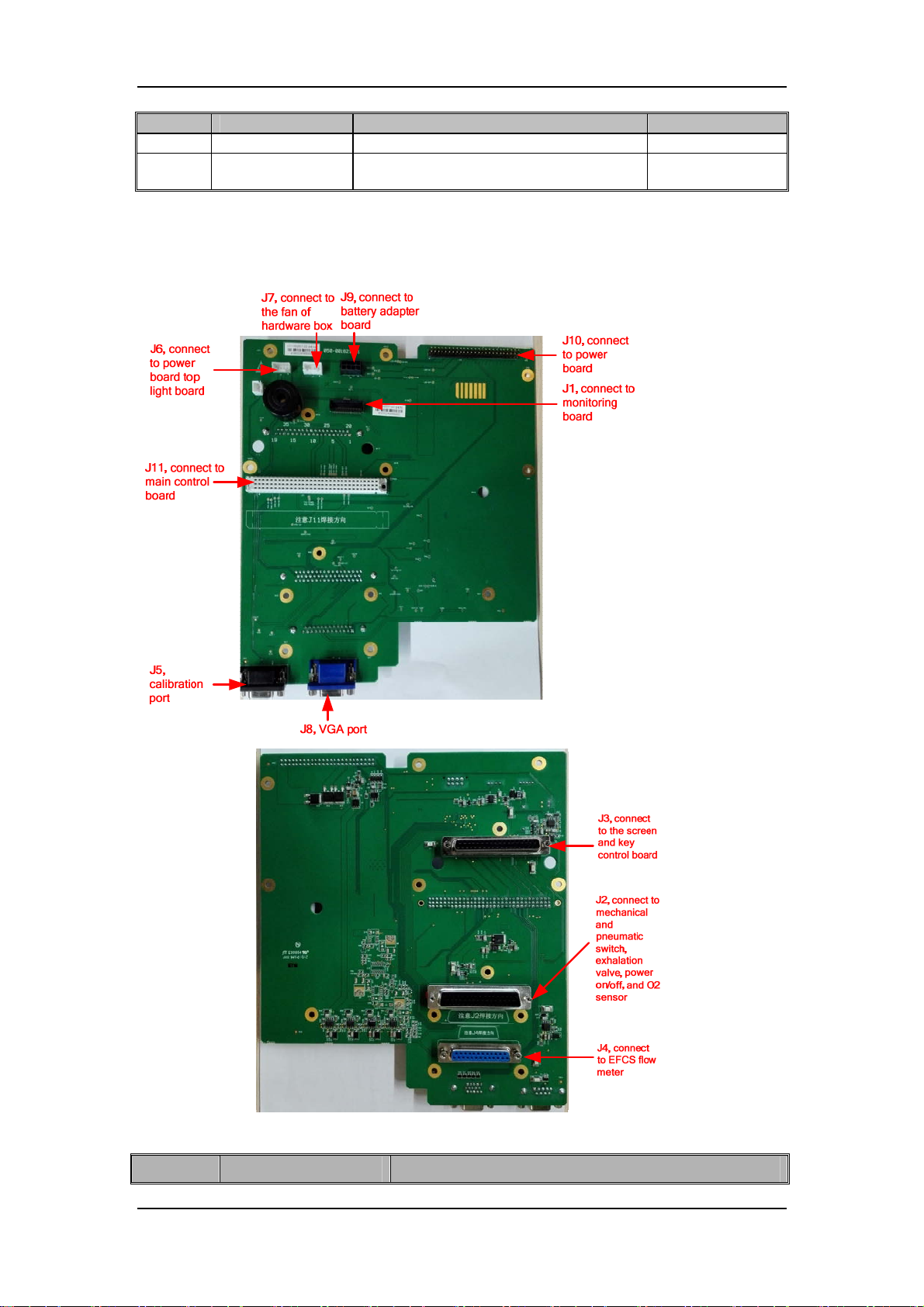
No. P/N Description Note
E15 9200-21-10633 2.25 speaker and connection line speaker
E16
012-000111-00
Sensor Pressure transmitter 4000psi
0.25%
Pressure sensor
2.1.3 Mother board
The mother board is mainly used for the signal transfer of various boards and electrical
components.
Definition of mother board J1 (with monitoring module interface)
Pin No. Signal name Description
2-6
Page 21

Pin No. Signal name Description
1) TXD_VPM2 Sent signal of VPM series port (reserved)
2) RXD_VPM2 Received signal of VPM series port (reserved)
3) 12VA +12V power supply
4) GND Ground
5) GND Ground
6) VPM_monitor_IO4 Status of drive gas selector valve
7) Driving_O2_control Monitoring signal of drive gas selector valve
8) 12VA +12V power supply
9) GND Ground
10) VF_Sensirion SENSIRION sensor output signal
11) TXD_VPM1 Sent signal of VPM series port (with main control board)
12) RXD_VPM1
13) TXD_VCM2 Sent signal of VCM series port (with calibration device)
14) RXD_VCM2
15) GND Ground
16) 5V +5V power supply
17) 12VA +12V power supply
18) GND Ground
19) TXD_VCM1 Sent signal of VCM series port (with main control board)
20) RXD_VCM1
21) O2+ O2 sensor +
22) O2- O2 sensor -
23) CO2_switch CO2 absorbent canister in-place switch
24) Huilu_switch Circuit switch
25) MANU_AUTO_switch Auto/manual switch
26) VPM_monitor_IO1 First reserved I/O monitoring signal of VPM
27) O2QIYUAN_switch Pressure switch at O2 supply inlet
28) VPM_control_IO2 Drive gas selector valve status 2
29) ACGO_switch ACGO switch
30) GND Ground
31) POWER_VERSION Reserved I/O monitoring signal of VPM
32) KUAI_O2 O2 flush switch
33) GND Ground
34) Qudongqiti_switch Drive gas pressure switch
35) VPEEP PEEP valve power supply
36) PEEP PEEP valve control signal
37) VXIQI Inspiration valve power supply
38) XIQI Inspiration valve control signal
39) VSAFE Safety valve power supply
40) SAFE Safety valve control signal
Received signal of VPM series port (with main control
board)
Received signal of VCM series port (with calibration
device)
Received signal of VCM series port (with main control
board)
2-7
Page 22

Definition of mother board J2 (pneumatic assembly port)
Pin No. Signal Name Discription
1) VSAFE Safety valve power supply
2) SAFE Safety valve control signal
3) VXIQI Inspiration valve power supply
4) XIQI Inspiration valve control signal
5) VPEEP PEEP valve power supply
6) PEEP PEEP valve control signal
7) Qudongqiti_switch Drive gas pressure switch
8) GND Ground
9) CO2_switch CO2 absorbent canister in-place switch
10) 12VA Power supply of drive gas selector valve
11) O2_DRIVING Drive gas selector valve control
12) O2QIYUAN_switch O2 pressure switch at gas source inlet
13) GND Ground
14) ACGO_switch Machinal ACGO status switch
15) MANU_AUTO_switch Auto/manual switch
16) GND Ground
17) Huilu_switch Circuit in-place switch
18) TXD_FLOW Sent signal of semi electronic flowmeter series port
19) RXD_FLOW Semi electronic flowmeter series port
20) GND Ground
21)
22) 12VA_Gasbench Infrared backplane 12V power supply
23) GND Ground
24) 3V3_Gasbench Infrared backplane power supply
25) GND Ground
26) RXD_HW_OR_JH
27) TXD_HW_OR_JH Sent signal of three-slot infrared module rack series port
28) 12VA_Flow_backlight Flowmeter backlight, 12 V power supply
29) GND Ground
30) 12VA_AGmodule Power supply of interrior AG module
31) GND Ground
32) RXD_AG_232 Received signal of interrior AG module
33) TXD_AG_232 Sent signal of interrior AG module
34) 12VA_Gasbench_FAN Red line, power supply
35) Fan_State2 Yellow line, status signal
36) GND Ground
37) LED_BAT1 Battery indicator
38) LED_AC1 AC indicator
39) PCON+(3.3V) Power on/off circuit 3.3V
40) PCON- Power on/off signal
41) O2+ Anode of O2 sensor
42) O2- Cathode of O2 sensor
43) Temperature-R11 Thermistor 1 signal
44) Temperature-R12 Thermistor 1 signal
45) Temperature-R21 Thermistor 2 signal
46) Temperature-R22 Thermistor 2 signal
47) P15V Heater drive voltage
48) P15V Heater drive voltage
49) GND Ground
12VA_WATO_Flowmet
er
Semi electronic flowmeter 12V power supply
Received signal of three-slot infrared module rack series
port
2-8
Page 23

Pin No. Signal Name Discription
50) GND Ground
Definition of mother board J3 (display assembly port)
Pin No. Signal Name Discription
1) LCDVGA4+ Display differential signal
2) LCDVGA4- Display differential signal
3) LCD3V3 Display dedicated 3.3V power supply
4) GND Ground
5) LCDCLK+ Display differential clock signal
6) LCDCLK- Display differential clock signal
7) GND Ground
8) LCDVGA3+ Display differential signal
9) LCDVGA3- Display differential signal
10) GND Ground
11) LCDVGA2+ Display differential signal
12) LCDVGA2- Display differential signal
13) GND Ground
14) LCDVGA1+ Display differential signal
15) LCDVGA1- Display differential signal
16) GND Ground
17) GND Ground
18) LCD3V3 Display dedicated 3.3V power supply
19) LCD3V3 Display dedicated 3.3V power supply
20) 12VA_AUX_Light +12V power sully of auxiliary light board
21) GND Ground
22) TXD_Touch Sent signal of key board series port
23) RXD_Touch Received signal of key board series port
24) TXD_KEY
25) RXD_KEY
26) SDA_CPU Main board IIC data signal
27) SCL_CPU Main board IIC clock signal
28) GND Ground
29) 5V_Touch_screen +5V power supply
30) GND Ground
31) 3V3_Keyboard +3.3V power supply
32) LCD_EN Backlight enable signal
33) LCD_BR Backlight brightness adjustment signal
34) GND Ground
35) GND Ground
36) 12VA_UI 12V power supply signal of backlight
37) 12VA_UI 12V power supply signal of backlight
Mother board J4 port (EFCS flowmeter port)
Pin No. Signal Name Discription
1) KUAI_O2 Air source pressure switch signal
2) GND Ground
3)
4) GND Ground
5) 12VB Power supply for the motor of EFCS flowmeter
6) 12VB Power supply for the motor of EFCS flowmeter
7) GND Ground
12VB_AutoFlowmeter
_FPGA
Sent signal of key board series port
(EFCS flowmeter knob)
Received signal of key board series port
(EFCS flowmeter knob)
12V power supply for main CPU of EFCS flowmeter
2-9
Page 24
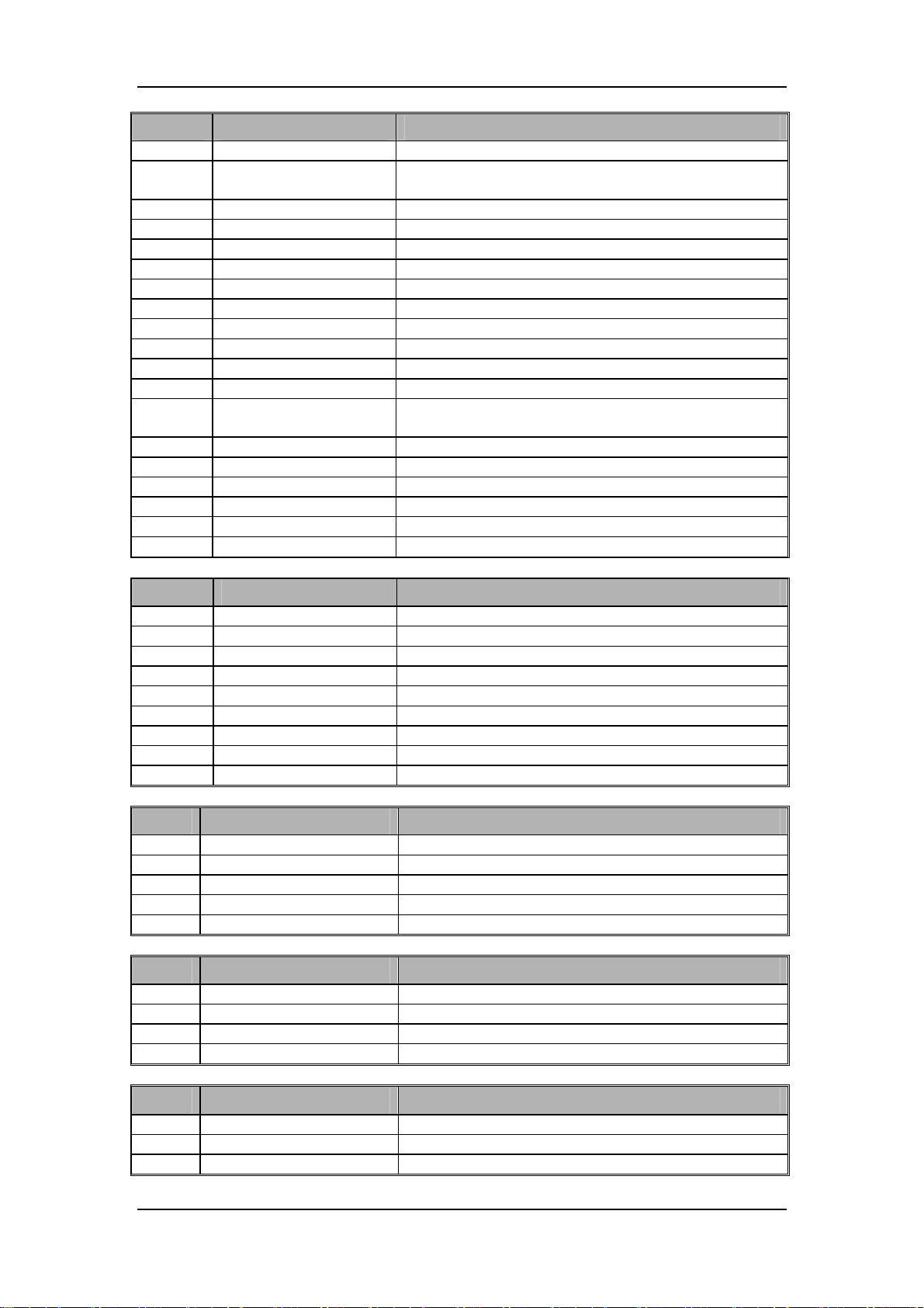
Pin No. Signal Name Discription
8) GND Ground
9)
10) GND Ground
11) GND Ground
12) TXD_FLOW Sent signal of series port
13) RXD_FLOW Received signal of series port
14) ACGO_State2_CN No connection
15) GND Ground
16) ACGO_State1_CN No connection
17) GND Ground
18) ACGO+ No connection
19) ACGO- No connection
20)
21) GND Ground
22) VBB Electromagnet power supply
23) VBB Electromagnet power supply
24) GND Ground
25) GND Ground
26) GND Ground
Definition of mother board J5 (calibration port)
Pin No. Signal Name Discription
1) NC No connection inside
2) NC No connection inside
3) NC No connection inside
4) NC No connection inside
5) GND Ground
6) 12VA 12V power supply output
7) RXD_VCM2 Received signal of alibration series port
8) TXD_VCM2 Sent signal of calibration series port
9) GND Ground
Definition of mother board J6 (top light board port)
Pin No. Signal Name Discription
1) 12VA 12V power supply signal
2) GND Ground
3) Lighting Brightness level control signal
4) Speaker+ Anode of speaker
5) Speaker- Cathode of speaker
Definition of mother board J7 (fan port of hardware box)
Pin No. Signal Name Discription
1) 12VA Power supply
2) Fan_PWM1 Fan PWM control signal
3) Fan_STATE1 Status signal
4) GND Ground
Definition of mother board J8 (VGA port)
PinNo. SignalName Discription
1) VGA_RED RED signal
2) VGA_GREEN GREEN signal
3) VGA_BLUE BLUE signal
VBB_AutoFlowmeter
_CPU
12VB_AutoFlowmeter
_Pro_valves
12V power supply for main and auxiliary CPU of EFCS
flowmeter
Power supply for the propotional valve of EFCS
flowmeter
2-10
Page 25
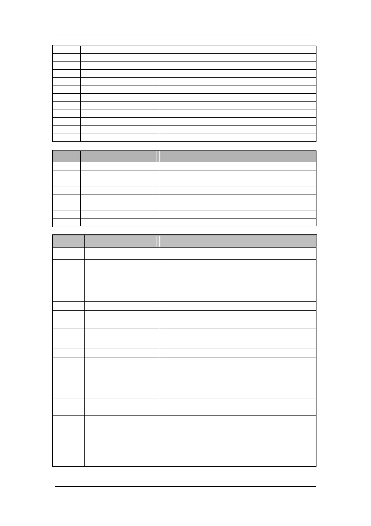
4) NC No connection inside
5) GND Ground
6) GND Ground
7) GND Ground
8) GND Ground
9) NC No connection inside
10) GND Ground
11) NC No connection inside
12) NC No connection inside
13) VGA_HSYNC VGA line frequency signal
14) VGA_VSYNC VGA audio signal
15) NC No connection inside
Definition of mother board J9 (battery adapter board port)
PinNo. SignalName Discription
1) BAT1+ Battery voltage
2) NTC1 Thermistor inside battery
3) BC1 Battery in-place signal
4) GND Ground
5) BAT2+ Electric
6) NTC2 Thermistor inside battery
7) BC2 Battery in-place signal
8) GND Ground
Definition of mother board J10 (power board port)
PinNo. SignalName Discription
1) PLAM Audio buzzer drive control signal
2) RXD_POWER Received signal of power board series port
3) Huilu_switch Circuit switch, indicating whether circuit is in-place
4) TXD_POWER
5) NC No connection inside
6) GND Ground
7) LED_BAT Battery indicator control signal
8) LCD_EN LCD backlight enable signal
9) LED_AC AC status indicator drive output
10) LCD_BR LCD backlight brightness adjustment control voltage
11) PCON-
12) PCON+ 3.3 V only for powering on/off
13) BAT2+
14) GND Ground
Sent signal of power board series port (received by main
control board)
Power on/off signal, LVTTL pulse signal. When it is
high level, the system powers on; when it is low level,
the system powers off.
Lithium battery 2 input, connected to the anode of
battery
15) BC2
Lithium battery 2 in-place signal. Low level indicates
there is battery; high level indicates there is no battery
2-11
Page 26

PinNo. SignalName Discription
16) NTC2
17) BAT1+
18) GND Ground
19) BC1
20) NTC1
21) GND Ground
22) GND Ground
23) P15V Heating wire drive voltage output
24) P15V Heating wire drive voltage output
25) Temperature-R12 Thermistor pin 1 of heating wire
26) Temperature-R22 Thermistor pin 1 of heating wire
27) Temperature-R11 Thermistor pin 2 of heating wire
28) Temperature-R21 Thermistor pin 2 of heating wire
29) GND Ground
30) GND Ground
31) 3V3 3.3V power supply voltage output
Lithium battery 2, connected with thermistor signal
inside
Lithium battery 1 input, connected to the anode of
battery
Lithium battery 1 in-place signal. Low level indicates
there is battery; high level indicates there is no battery
Lithium battery 1 connected with thermistor signal
inside
32) 3V3 3.3V power supply voltage output
33) 5V 5.0 V power supply voltage output
34) GND Ground
35) GND Ground
36) GND Ground
37) 12VB Second 12V power supply voltage output
38) GND Ground
39) 12VB Second 12V power supply voltage output
40) 12VB Second 12V power supply voltage output
41) GND Ground
42) GND Ground
43) 12VA First 12V power supply voltage output
44) GND Ground
45) 12VA First 12V power supply voltage output
46) 12VA First 12V power supply voltage output
47) NC No connection inside
48) 15.2V 15.2V power supply voltage output
49) NC No connection inside
50) 15.2V 15.2V power supply voltage output
2-12
Page 27

Definition of mother board J11 (main control board port)
Pin No. Signal Name Discription
1) LCD3V3 LCD power supply
2) GND Ground
3) NC No connection inside
4) NC No connection inside
5) RXD_HW_OR_JH Received signal of infrared backpanel or patient monitor
6) TXD_HW_OR_JH Sent signal of infrared backpanel or patient monitor
7) GND Ground
8) RXD_AG_232 Received signal of interior AG module
9) TXD_AG_232 Sent signal of interior AG module
10) GND Ground
11) Touchpad_5V 5V power supply of touchpad
12) Touchpad_usb+ Touchpad USB data signal+
13) Touchpad_usb- Touchpad USB data signal-
14) GND Ground
15) SCL_CPU Alarm light board IIC clock signal
16) SDA_CPU Alarm light board IIC data signal
17) GND Ground
18) MAIN_ACGO_CTRL2 ACGO control signal 2
19) NC No connection inside
20) ACGO_State1 ACGO status signal 1
21) NC No connection inside
22) FAN_State2 Fan status signal 2
23) FAN_State1 Fan status signal 1
24) GND Ground
25) 3V3 3.3V power supply of main control board
26) 3V3 3.3V power supply of main control board
27) GND Ground
28) GND Ground
29) 5V 5V power supply of main control board
30) 5V 5V power supply of main control board
31) GND Ground
32) GND Ground
33) NC No connection inside
34) NC No connection inside
35) NC No connection inside
36) SPEAK- Speaker drive signal +
37) SPEAK+ Speaker drive signal -
38) GND Ground
39) VGA_Red VGA red signal
2-13
Page 28

Pin No. Signal Name Discription
40) VGA_Green VGA green signal
41) VGA_Blue VGA cyan signal
42) VGA_HSYNC VGA line frequency signal
43) VGA_VSYNC VGA audio signal
44) GND Ground
45) RXD_POWER Received signal of power board series port
46) TXD_POWER Sent signal of power board series port
47) GND Ground
48) RXD_FLOW Received signal of EFCS flowmeter series port
49) TXD_FLOW Sent signal of EFCS flowmeter series port
50) GND Ground
51) RXD_Touch
52) TXD_Touch
53) OUT2 Backup output
54) ACGO_State2 ACGO status signal 2
55) GND Ground
56) NC No connection inside
57) DISPLAY_USB- USB data signal – of display adapter board
58) DISPLAY_USB+ USB data signal + of display adapter board
59) GND Ground
60) NC No connection inside
61) NC No connection inside
62) NC No connection inside
63) NC No connection inside
64) NC No connection inside
65) GND Ground
66) LCDVGA1- LVDS data signal
67) LCDVGA1+ LVDS data signal
68) GND Ground
69) LCDVGA2- LVDS data signal
70) LCDVGA2+ LVDS data signal
71) GND Ground
72) LCDVGA3- LVDS data signal
73) LCDVGA3+ LVDS data signal
74) GND Ground
75) LCDCLK- LVDS data signal
76) LCDCLK+ LVDS data signal
77) GND Ground
78) LCDVGA4- LVDS clock signal
Received signal of key board series port (for
communication with key board CPU actually)
Sent signal of key board series port (for communication
with key board CPU actually)
2-14
Page 29
Pin No. Signal Name Discription
79) LCDVGA4+ LVDS clock signal
80) GND Ground
81) RXD_VCM1
82) TXD_VCM1
83) GND Ground
84) RXD_VPM1 Received signal of auxiliary control module series port
85) TXD_VPM1 Sent signal of auxiliary control module series port
86) GND Ground
87) RXD_KEY Reserved series port signal
88) TXD_KEY Reserved series port signal
89) GND Ground
90) Touchpad_CON TouchPad power supply control signal
91) MAIN_ACGO_CTRL1 ACGO valve control signal 1
92) FAN_PWM1 Fan control signal
93) FAN_PWM2 Fan control signal
94) IN1 Backup input signal
95) NC No connection inside
96) NC No connection inside
Received signal of monitoring signal detection board
series port
Sent signal of monitoring signal detection board series
port
2.1.4 Power System
After the total AC mains inlet enters the anesthesia machine, it will be divided into two. One is
supplied to power board to transfer into the AC supply of the anesthesia machine; the other is
supplied to auxiliary output to supply the external devices of anesthesia machine.
2.1.4.1 Power Board
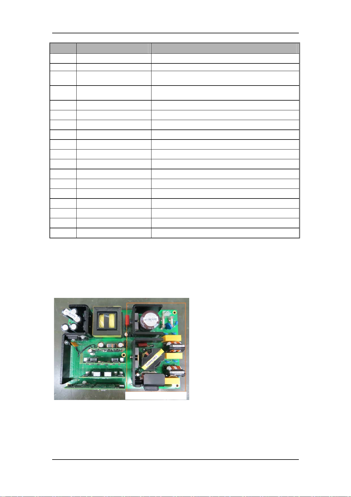
AC area
2-15
Page 30
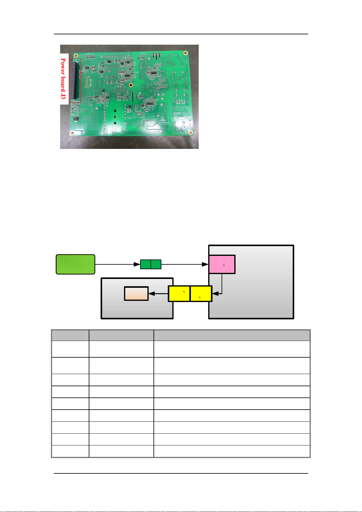
The power board can be divided into two parts: AC-DC, DC-DC. AC-DC part transforms the
network source into 15.2V direct voltage. DC-DC part transforms the 15.2V direct voltage
outputted by AC-DC part or lithium battery supply into several direct voltages needed by the
system: 12V, 5.0V and 3.3V. In addition, power board also realizes functions including
power-on/off control, AC indicator light, heating module drive, backlight switch control, and
lithium battery charging management, etc.
When powering on the system, power board CPU detectes the power-on signal, and control the
powering up of 3.3V, 5V, and 12V orderedly. When powering off the system, power down 12V, 5V,
and 3.3V orderedly.
Signal flow when powering on:
Abutting
joint
Power
009-001776-00
009-004712-00
switch
CPU
J3-11
12
Power Board
nition of power board J3
Pin No. Signal name Description
1)
2)
3)
4)
5)
6)
7)
8)
9)
RXD
TXD
GND ground
LCD-EN LCD backlight enable signal
LCD-BR LCD backlight brightness control voltage
3.3VBF only used for the 3.3V when powering on/off
GND ground
NTC2 Lithium battery 2, connecting to thermistor signal inside
GND ground
received through the communication of power board
series port
send through the communication of power board series
port
11
J10-
J2-11 12
Mother
Board
12
Defi
2-16
Page 31

Pin No. Signal name Description
10)
11)
NTC1 Lithium battery 1, connecting to thermistor signal inside
GND ground
12)
13)
14)
15)
16)
17)
18)
19)
20)
21)
22)
23)
24)
25)
26)
27)
28)
29)
30)
P15V
HRT22 Pin 1 of heating wire thermistor
HRT21 Pin 2 of heating wire thermistor
GND ground
3.3V 3.3V supply valtage output (Range: 3.135V to 3.465V)
GND ground
GND ground
GND ground
12V2 Second 12V supply valtage output (Range: 0V to 0.4V)
GND ground
GND ground
12V1 First 12V supply valtage output (Range: 10.8V to 13.2V)
15.2VB 15.2V supply valtage output (Range:14.44V to 15.96V)
15.2VB 15.2V supply valtage output (Range:14.44V to 15.96V)
PLAM
SWITCH Circuit switch indicating whether the circuit is in place
P-FAN+ Drive of heat-sink fan of power board
LED-BAT Drive output of battery status indicator light
LED-AC Drive output of AC status indicator light
Heating wire drive voltage output (Range:12.42V to
15.18V)
Audio buzzer drive signal which drives audio buzzer
directly
31)
32)
33)
34)
35)
36)
37)
38)
Power on/off signal, LVTTL signal. When this signal is
PCON
BAT2+
BC2
BAT1+
BC1
GND ground
P15V
HRT12 Pin 1 of heating wire thermistor
high level, the system is on; when this signal is low level,
the system is off.
Lithium battery 2 input, connecting to the anode of the
battery
With/without Lithium battery 2 signal. High level
indicates it is with battery; low level indicates it is without
battery.
Lithium battery 1 input, connecting to the anode of the
battery
With/without Lithium battery 1 signal. High level
indicates it is with battery; low level indicates it is without
battery.
Heating wire drive voltage output (Range:12.42V to
15.18V)
2-17
Page 32
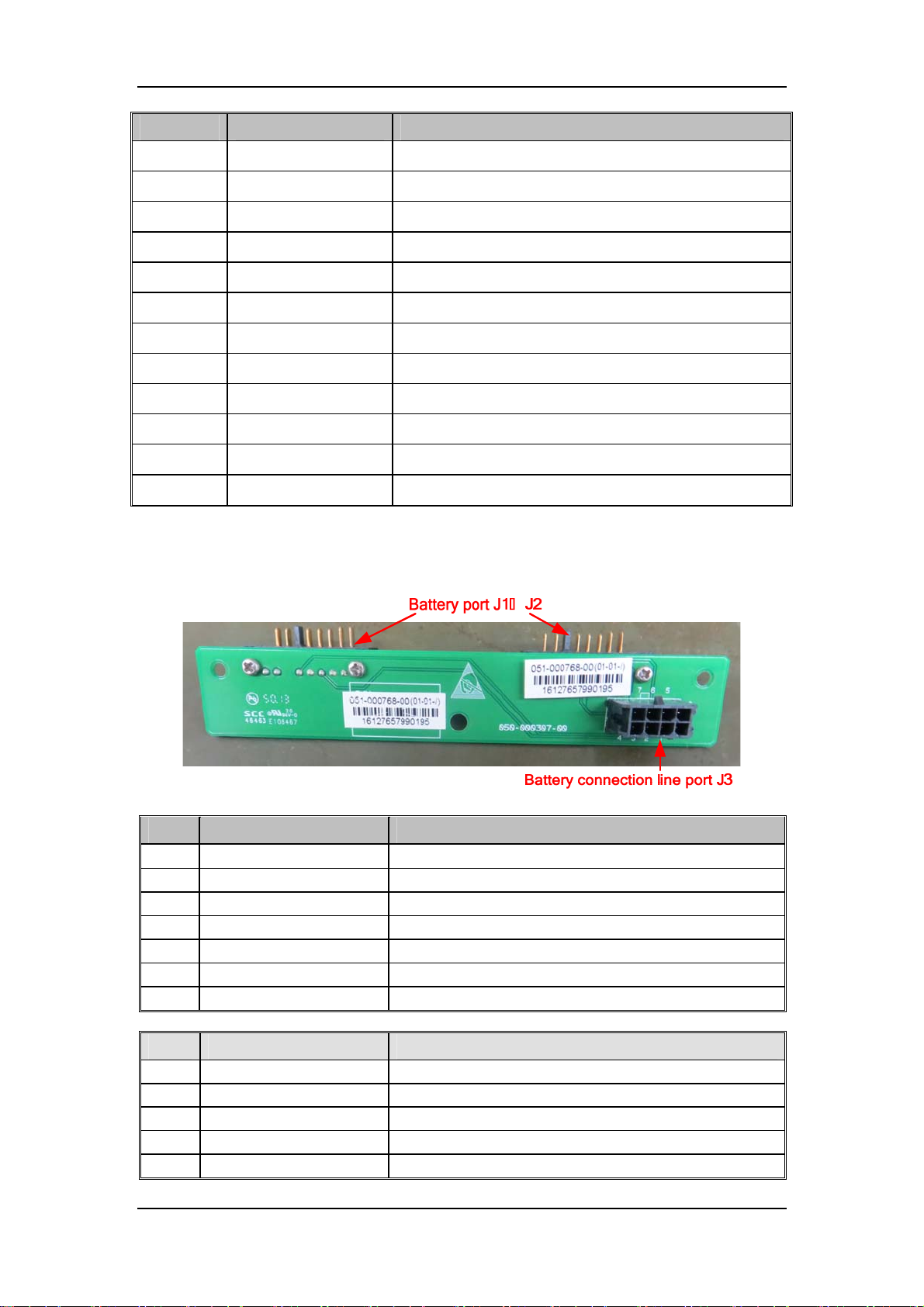
Pin No. Signal name Description
39)
40)
41)
42)
43)
44)
45)
46)
47)
48)
49)
50)
HRT11 Pin 2 of heating wire thermistor
GND ground
3.3V 3.3V supply valtage output (Range: 3.135V~3.465V)
5.0V 5.0V supply valtage output (Range: 4.75V~5.25V)
GND ground
12V2 Second 12V supply valtage output (Range: 0V to 0.4V)
12V2 Second 12V supply valtage output (Range: 0V to 0.4V)
GND ground
12V1 First 12V supply valtage output (Range: 10.8V to 13.2V)
12V1 First 12V supply valtage output (Range:10.8V to 13.2V)
NC No connection inside
NC No connection inside
2.1.4.2 Battery Adapter Board
Battery adapter board realizes transferring function: to transfer the signal of lithium battery to
mother board, and to transfer most of the signals to power board.
Battery port, J1 and J2
Pin Name Function
1)
2)
3)
4)
5)
6)
7)
Battery connection line port, J3
Pin Name Function
1)
2)
3)
4)
5)
BAT+ Battery voltage +
BAT+ Battery voltage +
BC Battery in-place signal
BAT- Battery voltage -
NTC Thermistor inside battery
BAT- Battery voltage -
BAT- Battery voltage -
VBAT1 Battery voltage
NTC1 Thermistor inside battery
BC1 Battery in-place signal
GND Ground
VBAT2 Battery voltage
2-18
Page 33
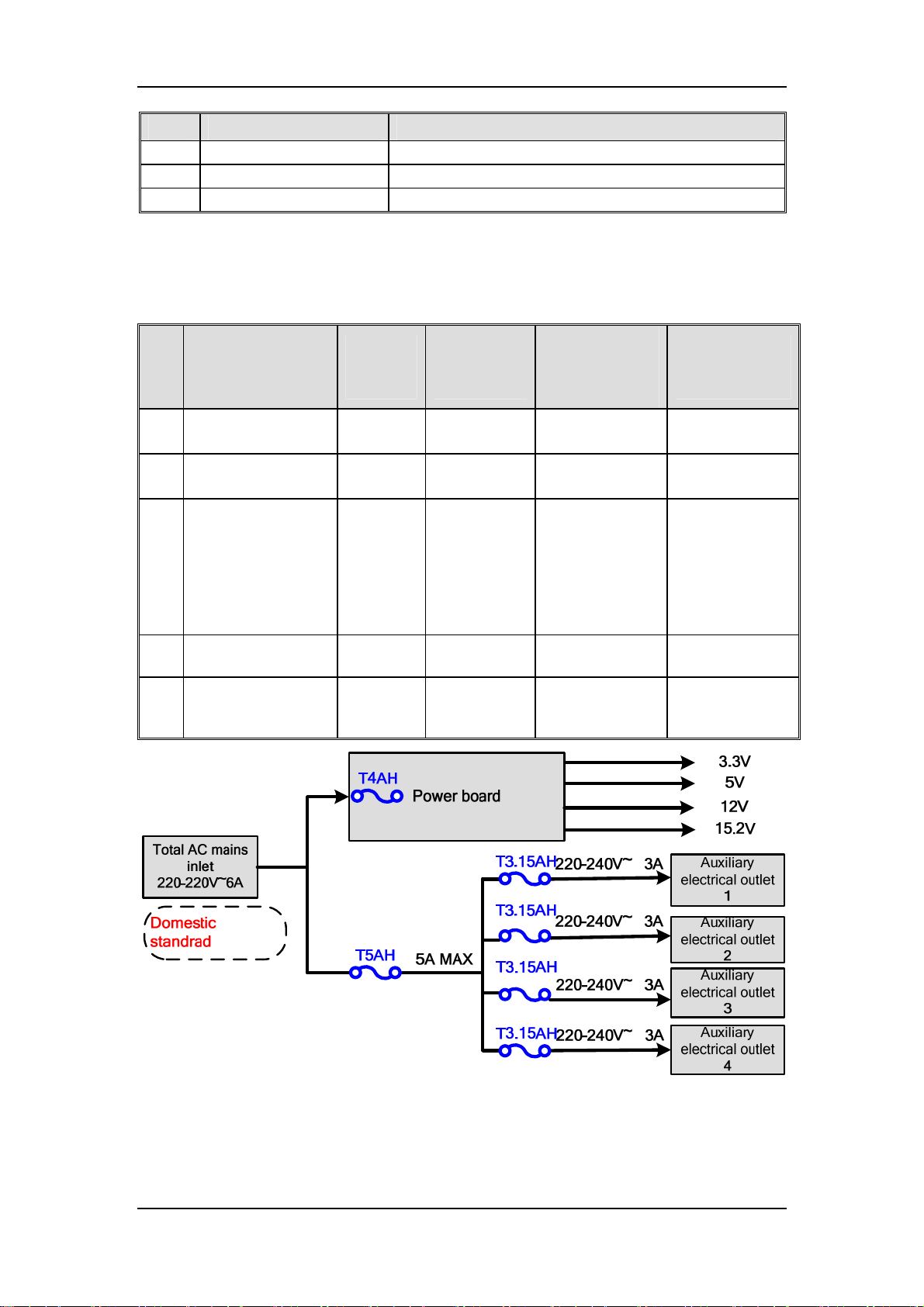
Pin Name Function
6)
7)
8)
NTC2 Thermistor inside battery
BC2 Battery in-place signal
GND Ground
2.1.4.3 Auxiliary Electrical Outlet
Auxiliary electrical outlet comes from total AC mains inlet, and it is to supply the external devices
of anesthesia machine.
Declaration of
total current of
auxiliary
electrical outlet
Declaration of
singal auxiliary
electrical outlet
No. Sales area
Auxiliary
electrical
outlet
Declaration
of AC mains
inlet
1)
Domastic standard 4
2)
American standard 4
European
standard/British
standard/Indian
3)
standard/Australian
standard/ B
specification/Brazili
an standard
South African
4)
standard
without auxiliary
5)
electrical outlet
configuration
4
3
None
220-240V~
6A 50/60Hz
100-120V~
7A 50/60Hz
100-240V~
7A 50/60Hz
100-240V~
7A 50/60Hz
100-240V~
7A 50/60Hz
5A MAX
5A MAX
5A MAX
5A MAX
None None
220-240V~ 3A
50/60Hz
100-120V~ 3A
50/60Hz
100-240V~ 3A
50/60Hz
100-240V~ 3A
50/60Hz
2-19
Page 34
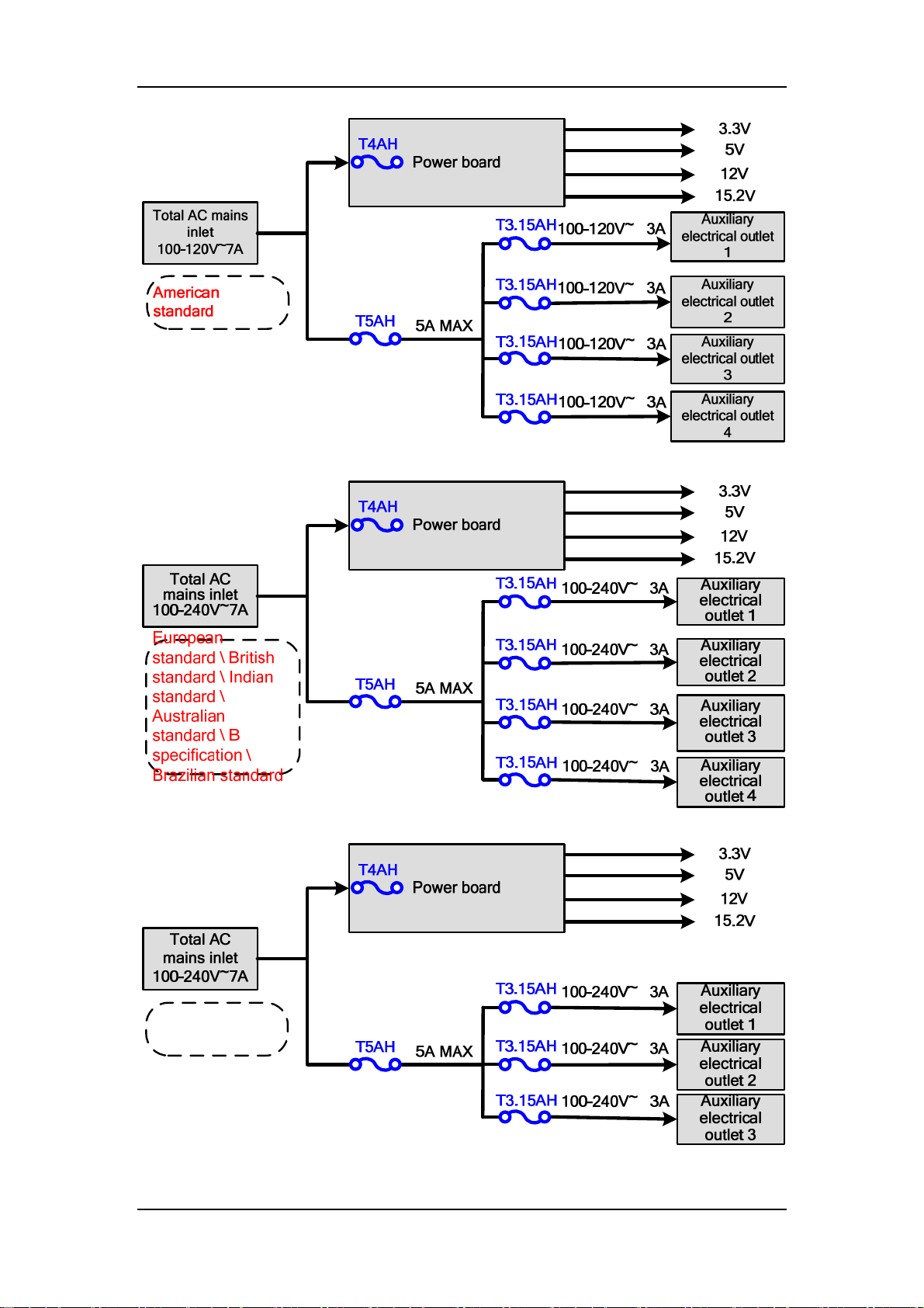
South African
standard
2-20
Page 35
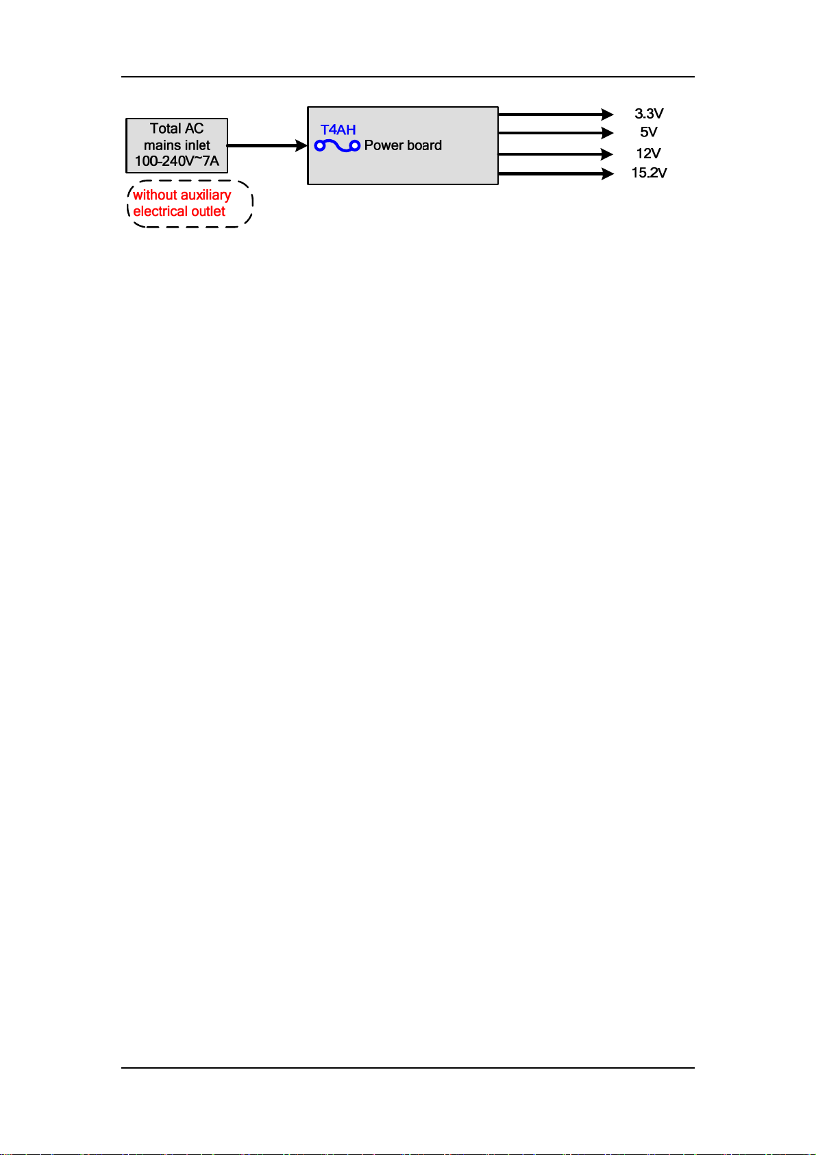
2.1.4.4 Others (heating module, fan, lithium battery)
Heating module, fan and lithium battery are also inside the anesthesia machine.
Heating module, drived by power board, offers temperature protection for software and hardware.
The mechanism of heating is: power board heats thermistor up to 90℃ with full power, and then
heats thermistor back to 70℃ with 5W, and then heats thermistor up to 90℃ with full power
again; go round and begin again. The heater is supplied by AC power. If the heater is not
connected to AC power, the heater does not work, and no alarm of heating module failure displays
on the screen of anesthesia machine.
Fans include fan of hardware box and fan of module rack, cooling hardware box and module rack
respectively. Lithium battery supplies the anesthesia machine without the network source, to
ensure that the anesthesia machine can work normally when the network source is disabled or
abnormal.
2.1.5 Display System
Display system includes key control board, screen, touchscreen, alarm light board, encoder board
(including main encoder and EFCS flowmeter encoder, of which only the main encoder is
illustrated here because of their same principle), etc, which realize human-machine interaction.
2.1.5.1 Key Control Adapter Board
Key control board realizes two functions, transferring signals and identification: one is to transfer
the signals of screen backlight drive, alarm light drive, and commnulication of touchscreen series
ports, etc; the other is to realize encoder identification, touchscreen identification and screen
backlight adjustment, etc.
2-21
Page 36
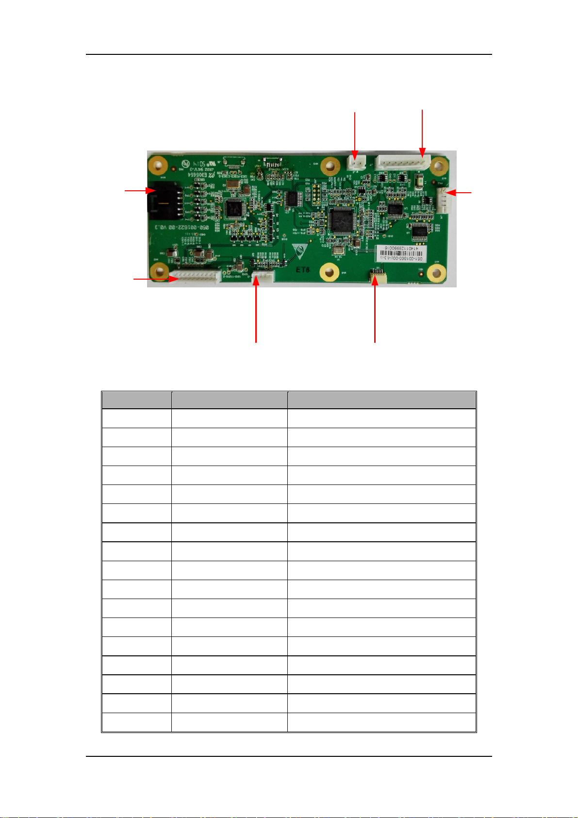
J6,connect to auxiliary
lighting board
J5, connect to
touchscreen
J1, connect to
mother board
J3,connect to screen
backlight port
J2,connect to
alarm light board
Definition of key control board J1 (port connected with mother board)
Pin No. Signal Name Discription
1)
2)
3)
4)
5)
6)
7)
8)
9)
10)
11)
12)
13)
14)
15)
16)
17)
12VA_AUX_Light
Light board, 12 V supply
SCL_CPU Main control board IIC clock signal
GND Ground
SDA_CPU Main control board IIC data signal
TXD_ENCODER Flowmeter knob series port sends sigal
TXD_KEY Key board series port sends signal
RXD_ENCODER Flowmeter knob series port receives sigal
RXD_KEY Key board series port receives signal
GND Ground
5V_Touch_screen
+5V supply
GND Ground
3V3_Keyboard
+3.3V supply
BCON Backlight enable signal
DIMMING Backlight brightness adjustment signal
12VA
12V supply
GND Ground
12VA
12V supply
J7, connect to EFCS
encoder
J4, connect
to encoder
2-22
Page 37
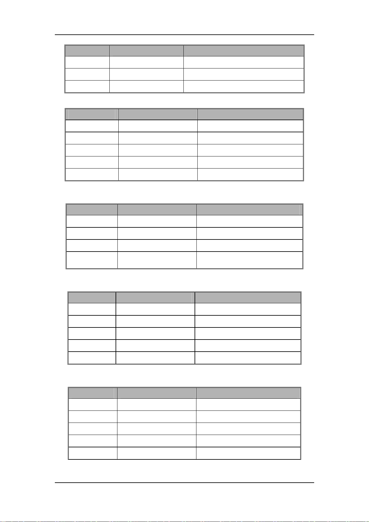
Pin No. Signal Name Discription
18)
19)
20)
Definition of key control board J2 (port connected with alarm light board)
Pin No. Signal Name Discription
1)
2)
3)
4)
5)
Definition of key control board J3 (port connected with screen backlight)
Pin No. Signal Name Discription
1)
2)
3)
GND Ground
12VA
GND Ground
12VA
GND Ground
SDA_CPU Main control board IIC data signal
SCL_CPU Main control board IIC clock signal
3V3_Keyboard
12VA
GND Ground
EN Backlight enable signal
12V supply
12V supply
3.3V supply
12V supply
4)
Definition of key control board J4 (port connected with encoder board)
Pin No. Signal Name Discription
1)
2)
3)
4)
5)
Definition of key control board J5 (port connected with touchscreen)
Pin No. Signal Name Discription
1)
2)
3)
4)
5)
PWM
5V_Touch_screen
A Encoder output A
B Encoder output B
S Encoder is pressed down
GND Ground
UR_H Touchscreen coordinate signal
LR_XL Touchscreen coordinate signal
AD3 Touchscreen coordinate signal
UL_YT Touchscreen coordinate signal
LL_YB Touchscreen coordinate signal
Backlight brightness adjustment
signal
5V supply
2-23
Page 38
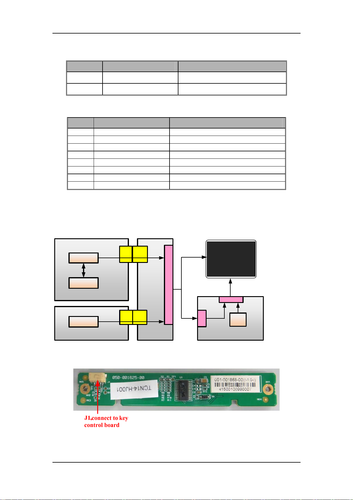
Definition of key control board J6 (port connected with auxiliary lighting board)
Pin No. Signal Name Discription
1)
2)
12VA_AUX_Light Light board, 12V supply
GND Ground
Definition of key control board J7 (port connected with EFCS flowmeter)
Pin No. Signal Name Discription
1) 5V_Touch_screen 5V supply
2) GND Ground
3) A1 Encoder 1 output A
4) B1 Encoder 1 output B
5) Y1 Encoder 1 is pressed down
6) A2 Encoder 2 output A
7) B2 Encoder 2 output B
8) Y2 Encoder 2 is pressed down
2.1.5.2 Screnn and Touchscreen
The machine configures with a screen of 15’’, 24 bits and 1024×768 resolution. The LCD
touchscreen of LVDS port is a 15” resistive touchscreen.
Signal flow of screen:
FPGA
CPU
LVDS
Bus
Main Board
Backlight
CPU
ON/OFF
Power Board
J11
J3
J3
J10
Mother
Board
009-006893-00
J3
LVDS
J1
LCD
Backlight
Key Control Board
009-006899-00
J3
Backlight
Adjust
CPU
2.1.5.3 Alarm Light Board
Red, yellow, and cyan alarm lights.
2-24
Page 39
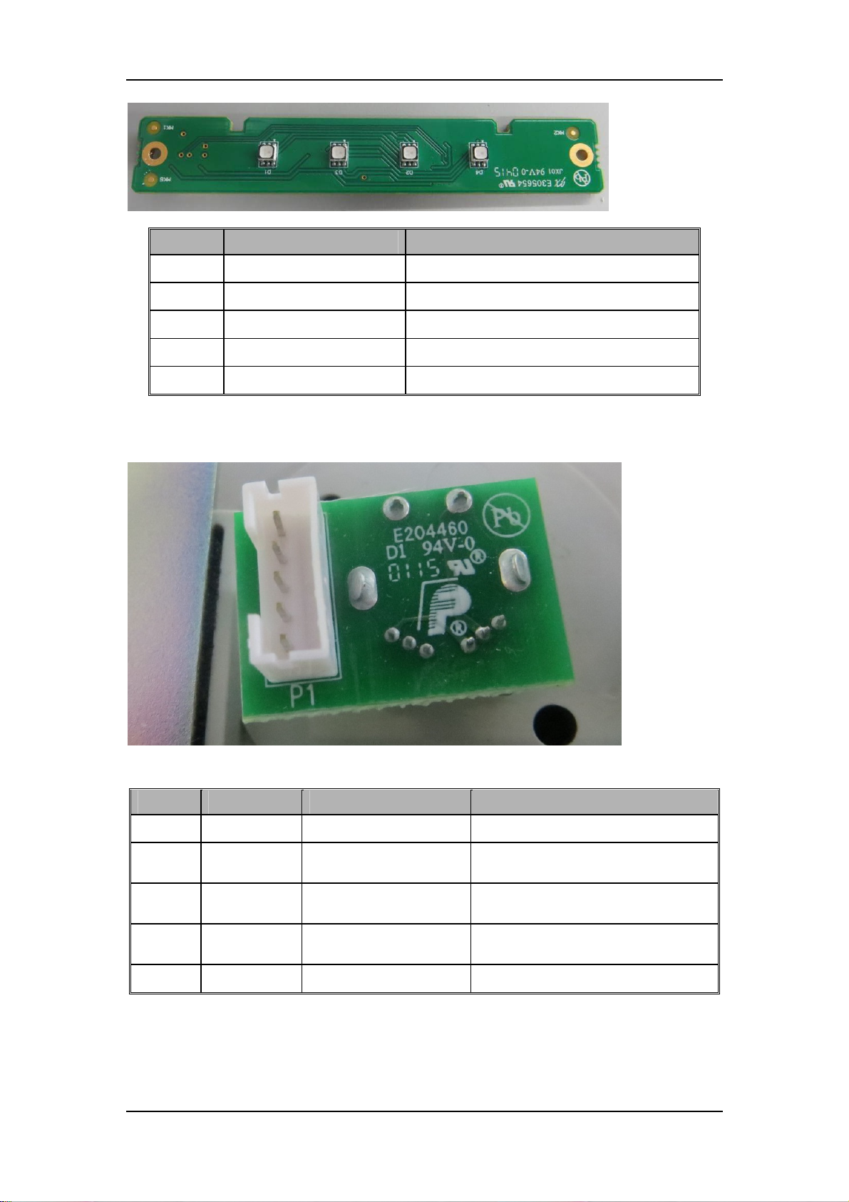
Definition of alarm light board J1
Pin No. Signal Name Discription
1)
2)
3)
4)
5)
VPP 12V supply
GND Ground
SDA Main control board IIC data signal
SCL Main control board IIC data signal
VDD 3.3V supply
2.1.5.4 Encoder Board
User can rotate it to left or right, or press it down.
Definition of encoder board J1
Pin No. Signal Name Discription Note
1)
2)
3)
4)
5)
VCC 5V supply 0.06A
A Encoder output A
B Encoder output B
S2 Encoder is pressed down
GND Ground /
2-25
High electrical level: [2.4, 5.25]V
Low electrical level: [0, 0.4]V
High electrical level: [2.4, 5.25]V
Low electrical level: [0, 0.4]V
High electrical level: [2.4, 5.25]V
Low electrical level: [0, 0.4]V
Page 40
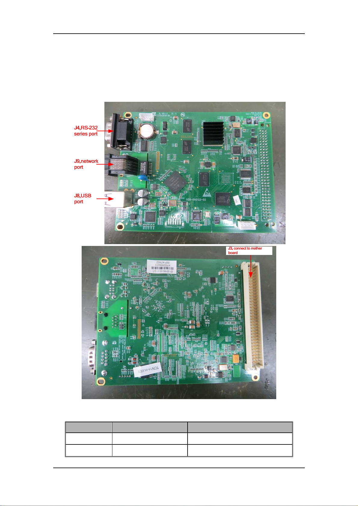
2.1.6 Control System
2.1.6.1 Main Control Board
Main control board is the main control component of human-machine interaction in anesthesia
machine. It drives the displays (including external display with VGA port) and speaker, and
exchanges data with monitoring module, flowmeter control board, key control board, and infrared
communication board through series ports.
Definition of main control board J3
Pin No. Signal Name Discription
1)
2)
GND Ground
GND Ground
2-26
Page 41

Pin No. Signal Name Discription
3)
4)
5)
6)
7)
8)
9)
10)
11)
12)
13)
14)
15)
16)
17)
18)
19)
20)
21)
22)
23)
VCC Main control board 5V supply
VCC Main control board 5V supply
GND Ground
GND Ground
VDD Main control board 3.3V supply
VDD Main control board 3.3V supply
GND Ground
FAN_STATE1_IN Fan status signal 1
FAN_STATE2_IN Fan status signal 2
AC_DET Detection signal of AC in-place
RSVD_IN3_IN Backup detection signal
DIMMING_OUT Backlight brightness adjustment signal
PCON Power on/off control signal
GND Ground
SDA IIC data
SCL IIC clock
GND Ground
DM3 USB3 data signal -
DP3 USB3 data signal +
UIVCC_USB USB 5Vsupply
GND Ground
24)
25)
26)
27)
28)
29)
30)
31)
32)
33)
34)
35)
RXD_TC
TXD_TC
GND Ground
RXD_KB
TXD_KB
BL_BCON Backlight enable signal
COLOR_SEL_LCD LCD color (18/24bits) choosing
GND Ground
LCDVDD Power supply of LCD
VCC_USB2 Power supply of USB2
DM2 USB2 data signal -
DP2 USB2 data signal +
Series port sent signal (with AG
module)
Series port received signal (with AG
module)
Series port sent signal (with module
rack)
Series port received signal (with
module rack)
2-27
Page 42

Pin No. Signal Name Discription
36)
37)
38)
39)
40)
41)
42)
43)
44)
DM1 USB1 data signal +
DP1 USB1 data signal -
GND Ground
DP0 USB0 data signal +
DM0 USB0 data signal -
VCC_USB1 Power supply of USB1
GND Ground
RSVD_IN2_IN Backup detection signal
OUT2 Backup output
45)
46)
47)
48)
49)
50)
51)
52)
53)
54)
55)
56)
57)
58)
59)
60)
61)
62)
63)
64)
RXD2_IF
TXD2_IF
GND Ground
RXD1_IF
TXD1_IF
GND Ground
RXD0_IF
TXD0_IF
GND Ground
VGA_VSN VGA audio signal
VGA_HSN VGA line frequency signal
VGA_B VGA cyan signal
VGA_G VGA green signal
VGA_R VGA red signal
GND Ground
SPKOUT+ Speaker drive signal -
SPKOUT- Speaker drive signal +
NC No connection inside
NC No connection inside
NC No connection inside
Series port received signal (with key
board)
Series port sent signal (with key
board)
Series port received signal (with
flowmeter)
Series port sent signal (with
flowmeter)
Series port received signal (with
power board)
Series port sent signal (with power
board)
65)
66)
SD_WP
SD_CD Detection signal of SD card in-place
Detection signal of SD crad writing
protection
2-28
Page 43
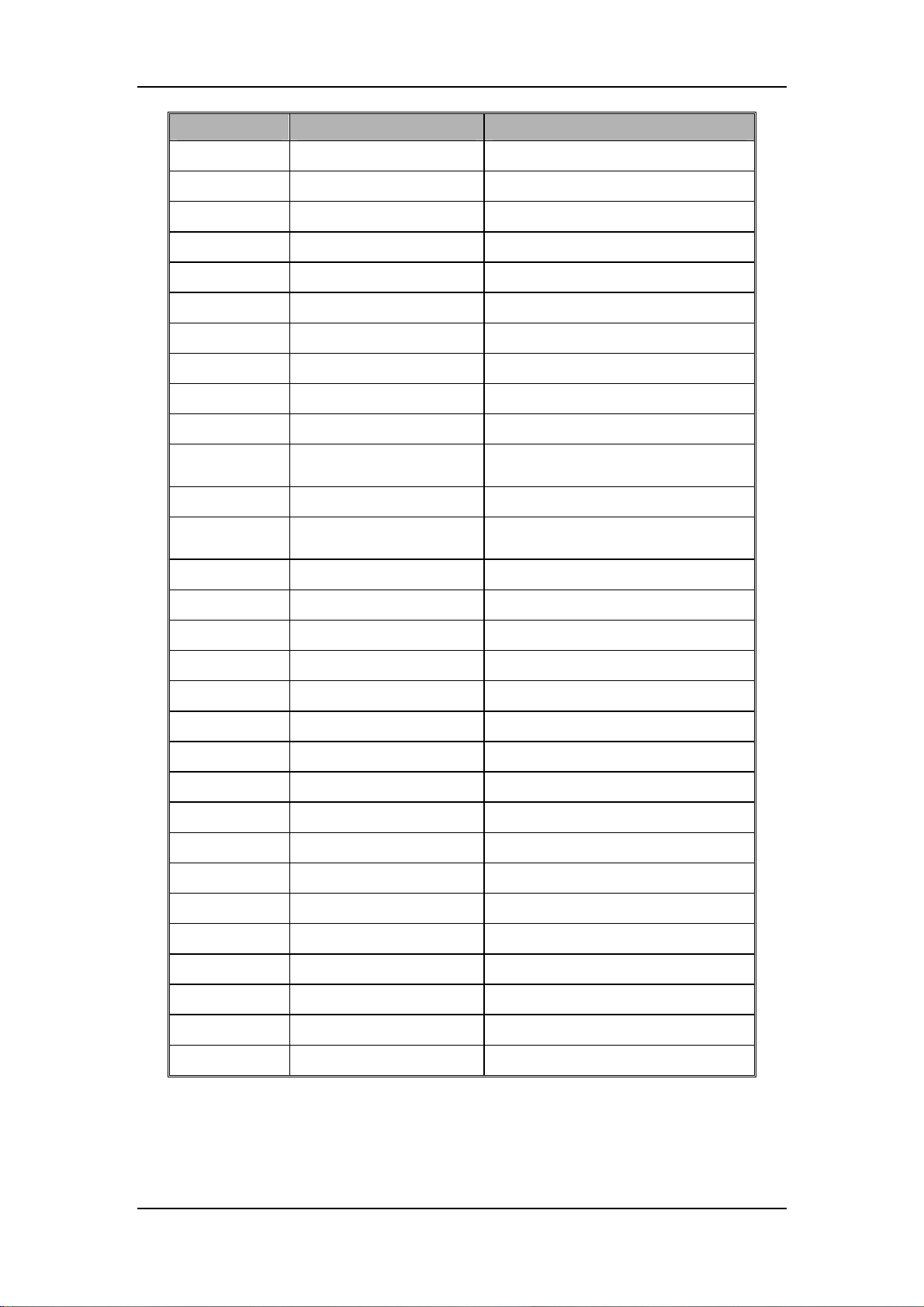
Pin No. Signal Name Discription
67)
68)
69)
70)
71)
72)
73)
74)
75)
76)
RSVD_IN1_IN Backup detection signal
FAN_PWM2_OUT Fan control signal 2
FAN_PWM1_OUT Fan control signal 1
RSVD_OUT1_OUT Safety valve control signal
TPPWR_CTRLOUT TouchPad supply control signal
GND Ground
RXD3_IF Series port received signal (reserved)
TXD3_IF Series port sent signal (reserved)
GND Ground
RXD_VPM Series port sent signal (with VPM)
77)
78)
79)
80)
81)
82)
83)
84)
85)
86)
87)
88)
89)
90)
91)
92)
93)
94)
95)
96)
TXD_VPM
GND Ground
RXD_VCM
TXD_VCM Series port sent signal (with VCM)
GND Ground
LCD_LVDS_Y3P LVDS data signal
LCD_LVDS_Y3M LVDS data signal
GND Ground
LCD_LVDS_CKLP LVDS clock signal
LCD_LVDS_CKLM LVDS clock signal
GND Ground
LCD_LVDS_Y2P LVDS data signal
LCD_LVDS_Y2M LVDS data signal
GND Ground
LCD_LVDS_Y1P LVDS data signal
LCD_LVDS_Y1M LVDS data signal
GND Ground
LCD_LVDS_Y0P LVDS data signal
LCD_LVDS_Y0M LVDS data signal
GND Ground
Series port received signal (with
VPM)
Series port received signal (with
VCM)
2-29
Page 44
Definition of main control board J4
Pin No. Signal Name Discription
1)
2)
3)
4)
5)
6)
7)
8)
9)
NC No connection inside
RXD RS-232 received
TXD RS-232 sent
NC No connection inside
GND Ground
NC No connection inside
NC No connection inside
NC No connection inside
NC No connection inside
Definition of main control board J8
Pin No. Signal Name Discription
1)
2)
3)
4)
5)
6)
7)
8)
Pin No. Signal Name Discription
1)
2)
3)
4)
5)
6)
7)
8)
VCC0 USB power supply
DM1 Positive signal of USB data
DP1 Negative signal of USB data
GND0 Ground
VCC1 USB power supply
DM2 Negative signal of USB data
DP2 Positive signal of USB data
GND1 Ground
Definition of main control board J9
TX+ Positive end of sent signal
TX- Negative end of sent signal
RX+ Positive end of received signal
CT1 No Definition
CT1 No Definition
RX- Negative end of received signal
CT2 No Definition
CT2 No Definition
2-30
Page 45
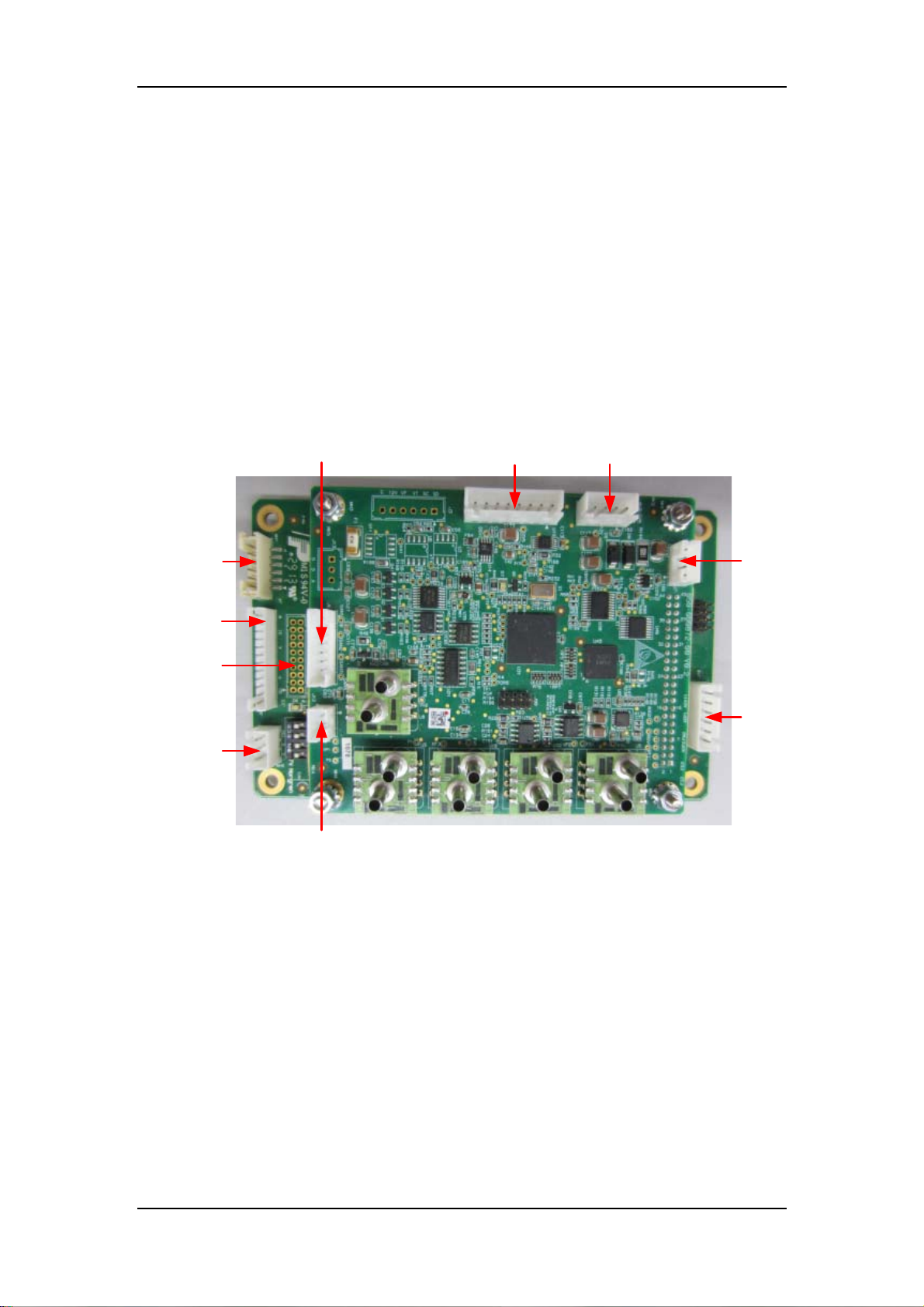
2.1.6.2 Monitoring Module
Monitoring module monitors pressure and flow of anesthesia machine and breathing system,
controls valves, monitors and collects statuses, reads O2 concentration, monitors pressure and
flow in circuit, and control accuracy accurately. Monitoring module contains VCM and VPM.
VCM monitrs the parameters including inspiratory flow, expiratory flow, interior flow of the
machine, airway pressure, PEEP, O2 concentration, etc, and controls the actions of three-way
valve and exhalation valve (including safety valve, PEEP valve, and inspiration valve).
VPM monitors the signal of the pressure switch of drive gas, ACGO limit switch, O2 pressure
switch at gas source inlet, auto/manual switch, CO2 absorbent canister in-place switch, etc. VPM
also controls the selector valve of drive gas, and controls safety valve with VCM, and send
monitoring information to the main board through series port.
J6, threeway valve
drive
J1, power supply
port and VCM
communication port
J5,VPM
communication port
J4,
exhalation
valve drive
J8, on/off
signal
J15, control
selector valve
of drive gas
J2,
Exhalation
valve Power
supply
J7,
communication
port of
calibration
J10,CO2
Absorber
canister
switch signal
J12, O2
sensor port
2-31
Page 46
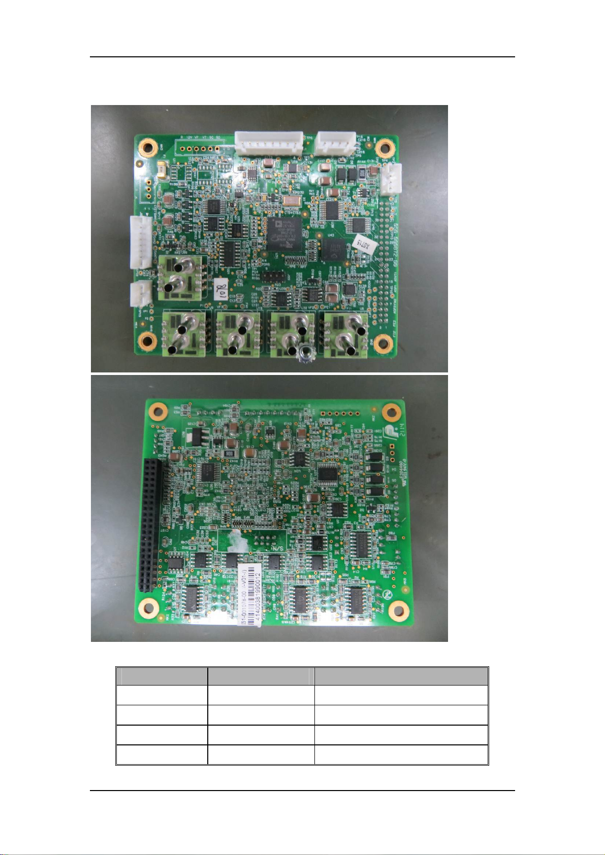
VCM
Definition of VCM J1
Pin No. Signal Name Discription
1)
2)
3)
4)
TXD Sent signal by series port
RXD Received signal by series port
VPP +12V power supply
GND Ground
2-32
Page 47
5)
6)
7)
8)
Pin No. Signal Name Discription
1)
2)
3)
4)
Pin No. Signal Name Discription
1)
2)
3)
4)
5)
GND Ground
VPP +12V power supply
PRST Safety valve control signal
VCC +5V power supply
Definition of VCM J5
TXD sent signal by series port
RXD Received signal by series port
GND Ground
VPP +12V power supply
Definition of VCM J6
VSAN Three-way valve power supply
SANTONG1-
VSAN Three-way valve power supply
SANTONG2- Three-way valve control 2 (pressure)
VSAN Three-way valve power supply
Three-way valve control 1
(inspiration)
6)
7)
8)
Pin No. Signal Name Discription
1)
2)
3)
4)
Pin No. Signal Name Discription
1)
2)
3)
SANTONG3-
VSAN Three-way valve power supply
SANTONG4- Three-way valve control 4 (ACGO)
Definition of VCM J7
TXD sent signal by series port
RXD Received signal by series port
GND Ground
VPP +12V
Definition of VCM J12
O+ Anode of O2 sensor
O- Cathode of O2 sensor
GND Ground
Three-way valve control 3
(expiratioj)
2-33
Page 48
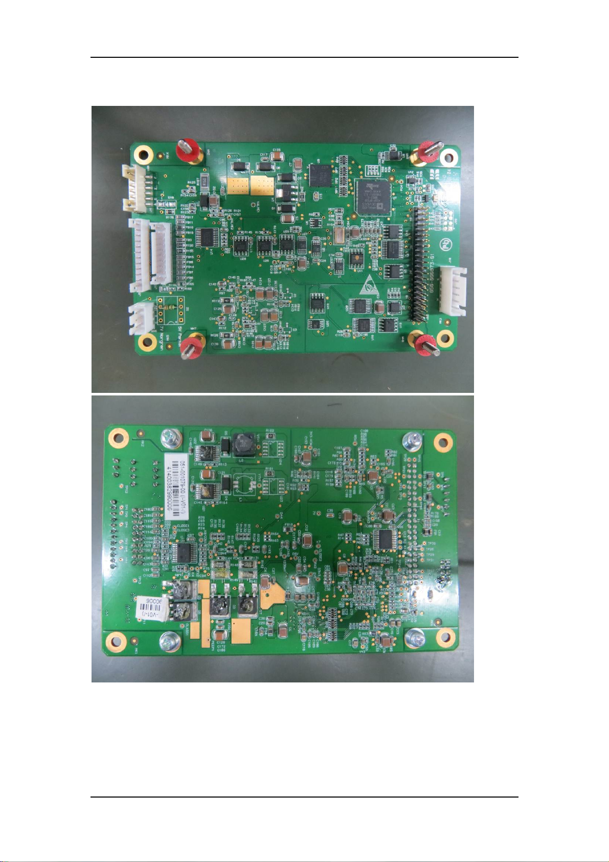
VPM
2-34
Page 49
Definition of VPM J2
Pin No. Signal Name Discription
1)
2)
3)
Pin No. Signal Name Discription
1)
2)
3)
4)
5)
6)
GND Ground
GND Ground
VB 12V power supply of exhalation valve
Definition of VPM J4
VSAFE 7V power supply of safety valve
SAFE Safety valve control signal
VXIQI_PEEP 7V power supply of inspiration valve
FLOW Inspiration valve control signal
VXIQI_PEEP 7V power supply of PEEP valve
PEEP PEEP valve control signal
Definition of VPM J8
Pin No. Signal Name Discription
1)
2)
3)
4)
5)
6)
7)
8)
9)
10)
11)
12)
GND Ground
QUDONGQITI Pressure switch signal of circuit block
GND Ground
POWER_VERSION Reserved switch signal
GND Ground
KUAI_O2 O2 flush switch
GND Ground
ACGO_Switch ACGO switch signal
GND Ground
QIYUANO2_Switch
GND Ground
MANU_AUTO_Swit
ch
Switch signal of O2 pressure at gas
source inlet
Auto/manual switch signal
2-35
Page 50
Definition of VPM J10
Pin No. Signal Name Discription
1)
2)
3)
4)
GND Ground
CO2_SWITCH CO2 absorbent canister switch signal
GND Ground
GND Ground
5)
6)
Pin No. Signal Name Discription
1)
2)
3)
4)
5)
6)
7)
8)
9)
10)
11)
12)
13)
14)
15)
16)
17)
18)
19)
HUILU_SWITCH Circuit switch signal
GND Ground
Definition of VPM J15
GND Ground
GND Ground
IN1
GND Ground
GND Ground
GND Ground
IN2
EXTEND_OUT2 Reserved I/O control signal 2
DA_C Reserved DA control signal
TXD
VCC Reserved 5V power supply signal
RXD
GND Ground
GND Ground
IN3
EXTEND_OUT3
GND Ground
GND Ground
IN4
Reserved switch monitor signal 1
(AD)
Reserved switch monitor signal 2
(AD)
Sent signal of reserved VPM series
port
Sent signal of reserved VPM series
port
Reserved switch monitor signal 3
(AD)
Drive gas selector valve control
signal
Status monitoring signal of drive gas
selector valve
20)
EXTEND_OUT4 Reserved I/O control signal 4
2-36
Page 51
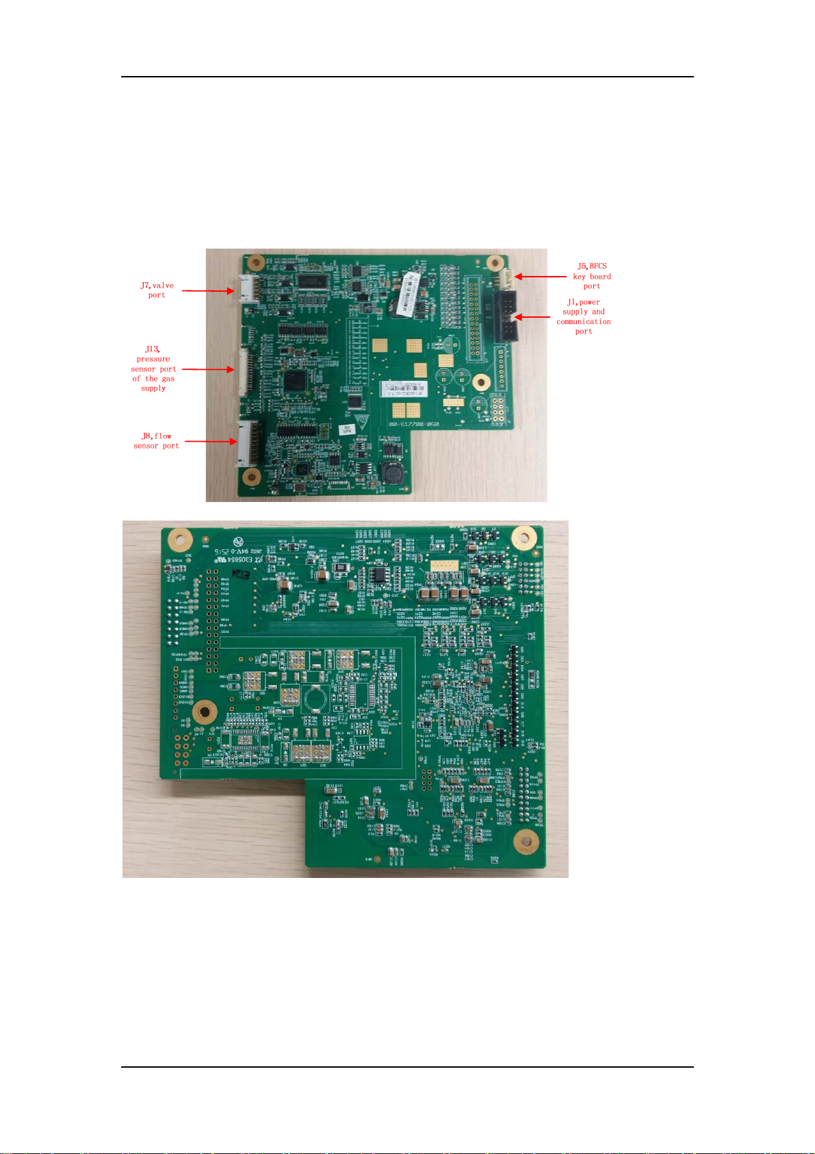
2.1.7 EFCS flowmeter system
2.1.7.1 EFCS VCM
The EFCS VCM is the core control component of the EFCS on the anesthesia machine. The EFCS
VCM controls the oxygen, nitrous oxide and air flow by regulating the proportional valves, and
monitors and feeds back the oxygen, nitrous oxide and air flow by using a flow sensor. In addition,
the EFCS VCM can identify the switch of the backup flowmeter system and control the backlight.
The EFCS VCM communicates with the main control board through the serial port.
2-37
Page 52
Definition of EFCS VCM J1
Pin No. Signal Name Description
1) VPM_VPP Auxilliary CPU power supply
2) GND Ground
3) VCM_VPP Main CPU power supply
4) GND Ground
5) PRO_VALVE_VPP 12V power supply for proportional valve
6) GND Ground
7) NC Not connected
8) GND Ground
9) VCM_TX_GUI
10) GND Ground
11) VCM_RX_GUI_S
12) GND Ground
13) VPM_RX_GUI_S
14) VPM_TX_GUI
Sent signal by communication serial port of the main
control board
Received signal by communication serial port of the
main control board
Received signal by communication serial port of the
main control board
Sent signal by communication serial port of the main
control board
Definition of EFCS VCM J5
Pin No. Signal Name Description
1) LED_POWER Power supply
2) KEY_BFCS_IN Key signal
3) GND Ground
Definition of EFCS VCM J7
Pin No. Signal Name Description
1) OUT_VA Anode of the proportional valve
2) OUT_VB Cathode of the proportional valve
3) OUT_VA Anode of the proportional valve
4) OUT_VB Cathode of the proportional valve
5) VCM_VPP 12V power supply
6) 3Way_AIR Cathode of the three-way valve
7) VCM_VPP 12V power supply
8) 3Way_N2O Cathode of the three-way valve
9) PRO_VALVE_VPP 12V power supply
10) NOValve Cathode of NO valve
11) DVCC 5V power supply
12) NCValve Cathode of NC valve
Definition of EFCS VCM J8
Pin No. Signal Name Description
1) SCL_REV I2C clock signal
2) VCCB Sensor power supply
3) SDA_REV I2C data signal
2-38
Page 53
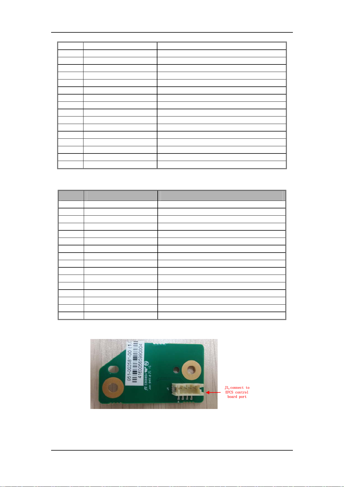
4) VDDB Sensor signal conversion pin
5) GND Ground
6) GND Ground
7) DVCC Sensor power supply
8) SCL _O2 I2C clock signal
9) VDD Sensor signal conversion pin
10) SDA_O2 I2C data signal
11) SCL_BALANCE I2C clock signal
12) DVCC Sensor power supply
13) SDA_BALANCE I2C data signal
14) VDD Sensor signal conversion pin
15) GND Ground
16) GND Ground
17) DVCC Sensor power supply
18) SCL_TOTAL I2C clock signal
19) VDD Sensor signal conversion pin
20) SDA_TOTAL I2C data signal
Definition of EFCS VCM J13
Pin No. Signal Name Description
1) Cylinder1_O2 Pressure sensor signal
2) Cylinder2_O2 Pressure sensor signal
3) GND Ground
4) AVCC Power supply signal
5) GND Ground
6) Cylinder_AIR Pressure sensor signal
7) Cylinder_N2O Pressure sensor signal
8) GND Ground
9) AVCC Power supply signal
10) Pipeline_O2 Pressure sensor signal
11) GND Ground
12) AVCC Power supply signal
13) Pipeline_AIR Pressure sensor signal
14) Pipeline_N2O Pressure sensor signal
15) GND Ground
16) AVCC Power supply signal
2.1.7.2 Flowmeter control board
2-39
Page 54
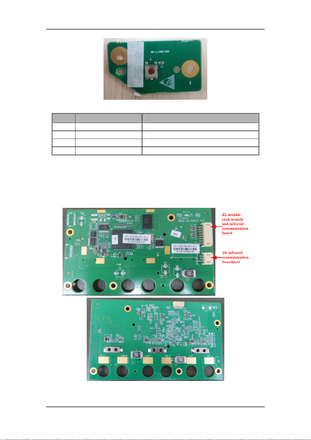
Definition of flowmeter control board J1
Pin No. Signal Name Description
1) 5V Not connected
2) GND Ground
3) Key Key signal
4) GND Ground
2.1.8 Gas parameter system
2.1.8.1 Infrared communication board
Infrared communication board offers power supply to module rack module, and receives
parameters monitored by AG module, CO2 module and BIS module, and then send these
parameters to main control board through series port.
2-40
Page 55
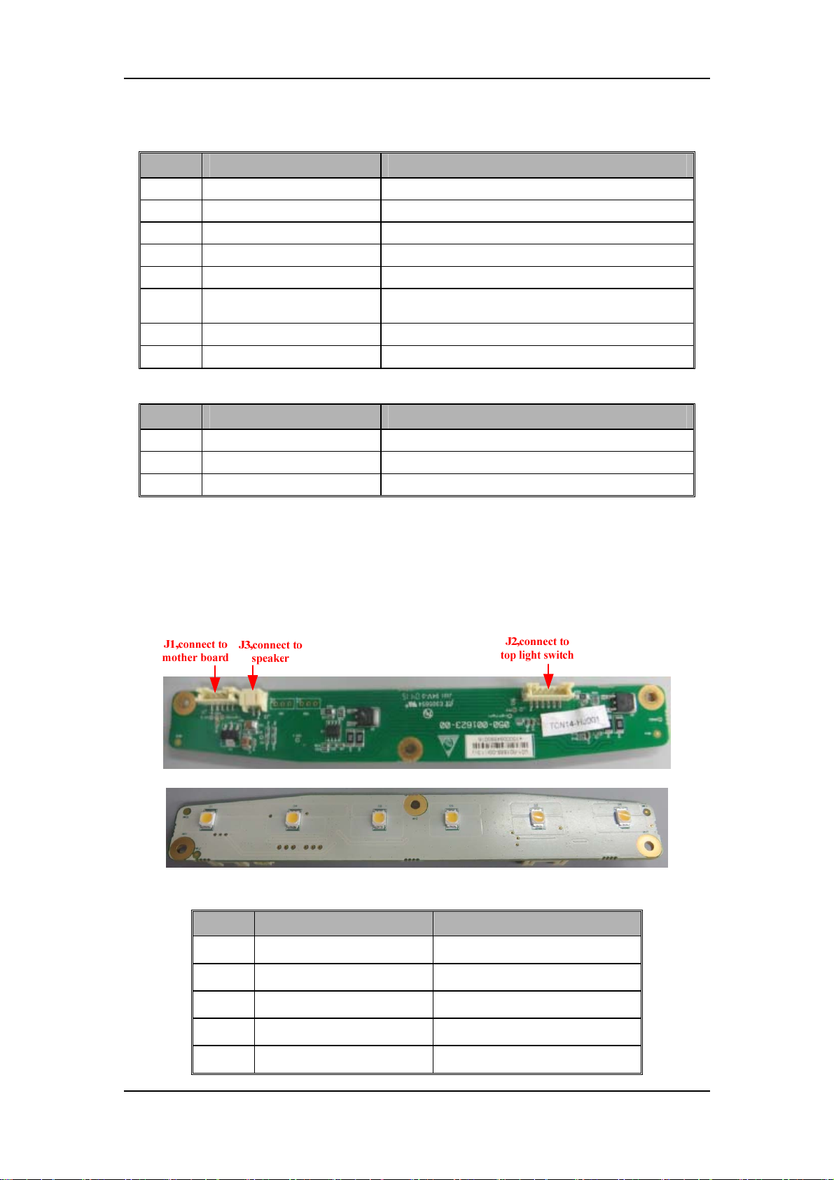
Definition of infrared communication board J2
Pin No. Signal Name Description
1)
2)
3)
4)
5)
6)
7)
8)
Pin No. Signal Name Description
1)
2)
3)
VPP 12V power supply
VPP 12V power supply
GND Ground
GND Ground
VDD 3.3V power supply
VCC
GND Ground
GND Ground
Definition of infrared communication board J4
INTERFACE_TX0 Sent signal of infrared communication board
INTERFACE_RX0 Received signal of infrared communication board
GND Ground
5V power supply(IO pull power
supply)
2.1.9 Others
2.1.9.1 Top Light Board
Top light board supports two levels of top lighting: high light and low light. And it also transfers
the signal of speaker.
Definition of top light board J1 (port connect with the mother board)
Pin No. Signal Name Discription
1)
2)
3)
4)
5)
VPP 12V power supply signal
GND Ground
Lighting Brightness level control signal
Speaker+ Anode of speaker
Speaker- Cathode of speaker
2-41
Page 56
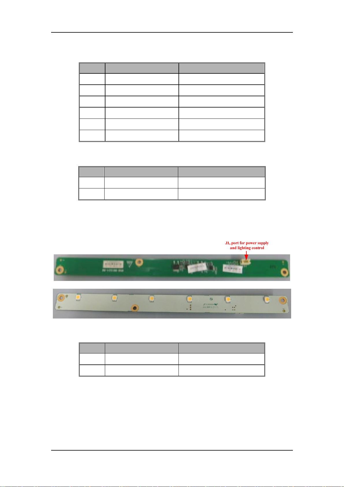
Definition of top light board J2 (three-level switch port)
Pin No. Signal Name Discription
1)
2)
3)
4)
5)
6)
Pin No. Signal Name Discription
1)
2)
LOW Low-light level
LOW Low-light level
COM Off
COM Off
High High-light level
High High-light level
Definition of top light board J3 (speaker port)
Speak+ Speak positive
Speak- Speak negative
2.1.9.2 Auxiliary Light board
Auxiliary light board, controlled by the top light board switch, is to light the worktable. When the
switch of top light board is set to ligh-light level or low-light level, the auxiliary light lights;
otherwise, the auxiliary light is out.
Definition of auxiliary light board J1
Pin No. Signal Name Discription
1)
2)
12VA_AUX_Light 12V power supply of light board
GND Ground
2-42
Page 57
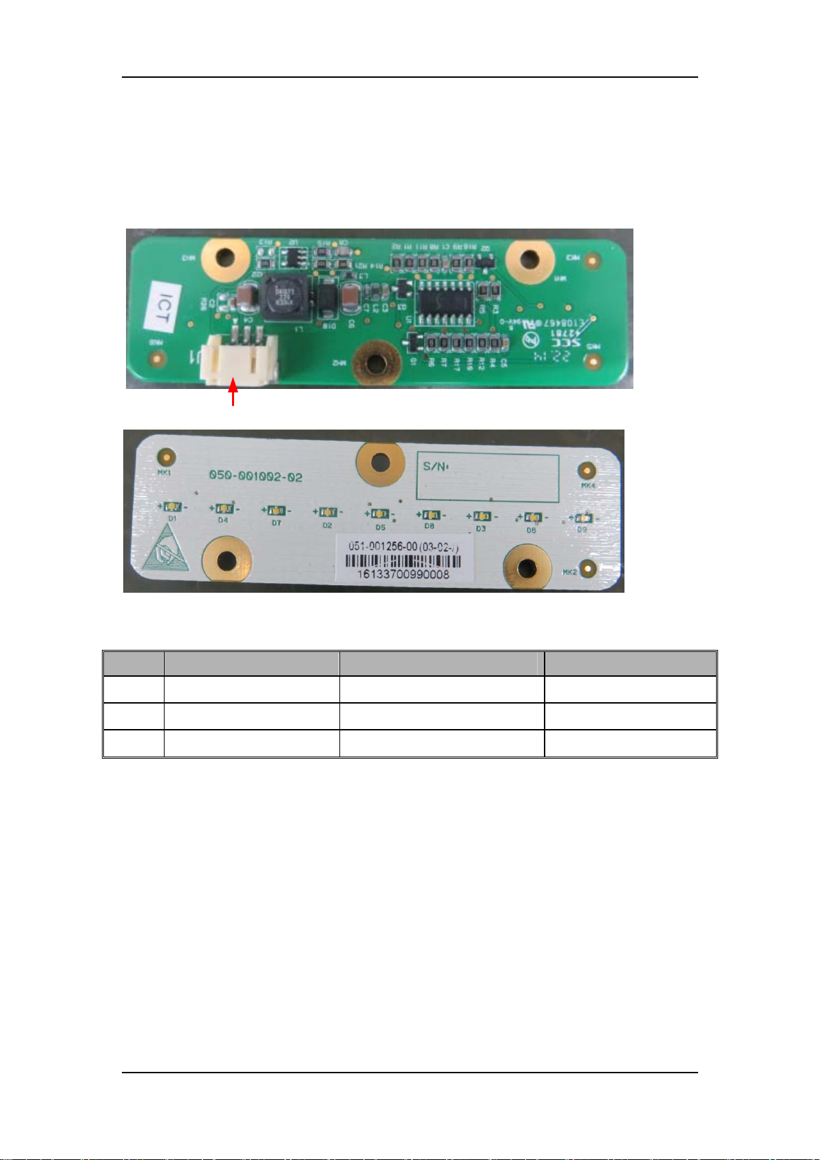
2.1.9.3 Flowmeter Backlight Board
Flowmeter backlight board is to light the auxiliary flowmeter and backup flowmeter. The backup
flowmeter is controlled by the top light board switch. When the switch of top light board is set to
ligh-light level or low-light level, the auxiliary light lights; otherwise, the auxiliary light is out.
The backup flowmeter is controlled by the EFCS VCM. When the backup flow control system
powers on, the auxiliary light lights; otherwise, the auxiliary light is out.
J1, power supply port
Definition of flowmeter backlight board J1
Pin No. Signal Name Discription Note
1)
2)
3)
VPP 12V power supply /
Lighting Control signal /
GND Ground /
2-43
Page 58
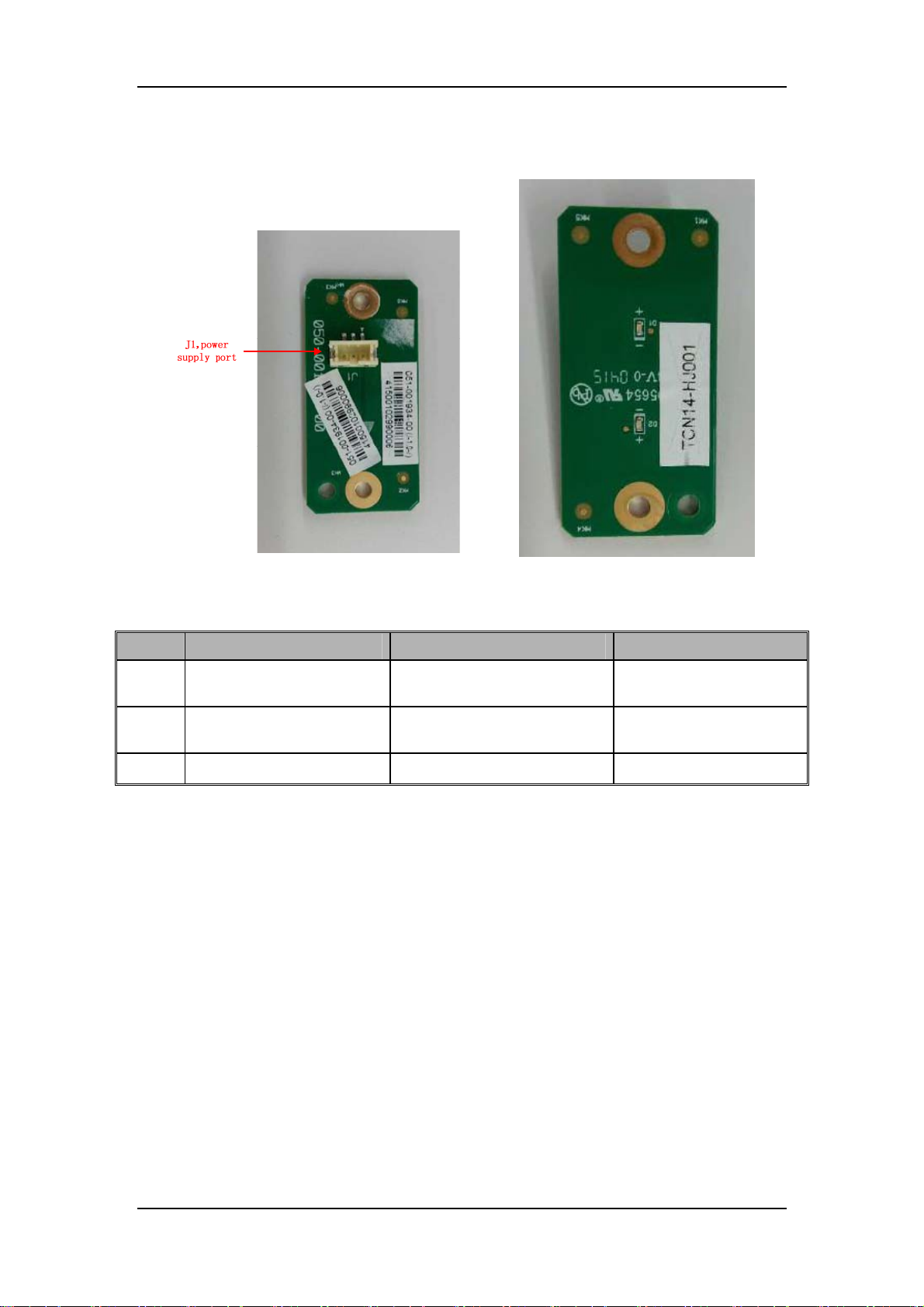
2.1.9.4 Indicator Board
Indicator board supports the functions of AC power indicator and battery indicator.
Indicator board (Top) Indicator board (Bottom)
Definition of indicator J1
Pin No. Signal Name Discription Note
1)
2)
3)
LED_BAT Battery indicator drive signal
LED_AC
GND Ground /
AC power indicator drive
signal
High level: [2.5,3.5]V
Low level: [0~0.4]V
High level: [2.5,3.5]V
Low level: [0~0.4]V
2-44
Page 59
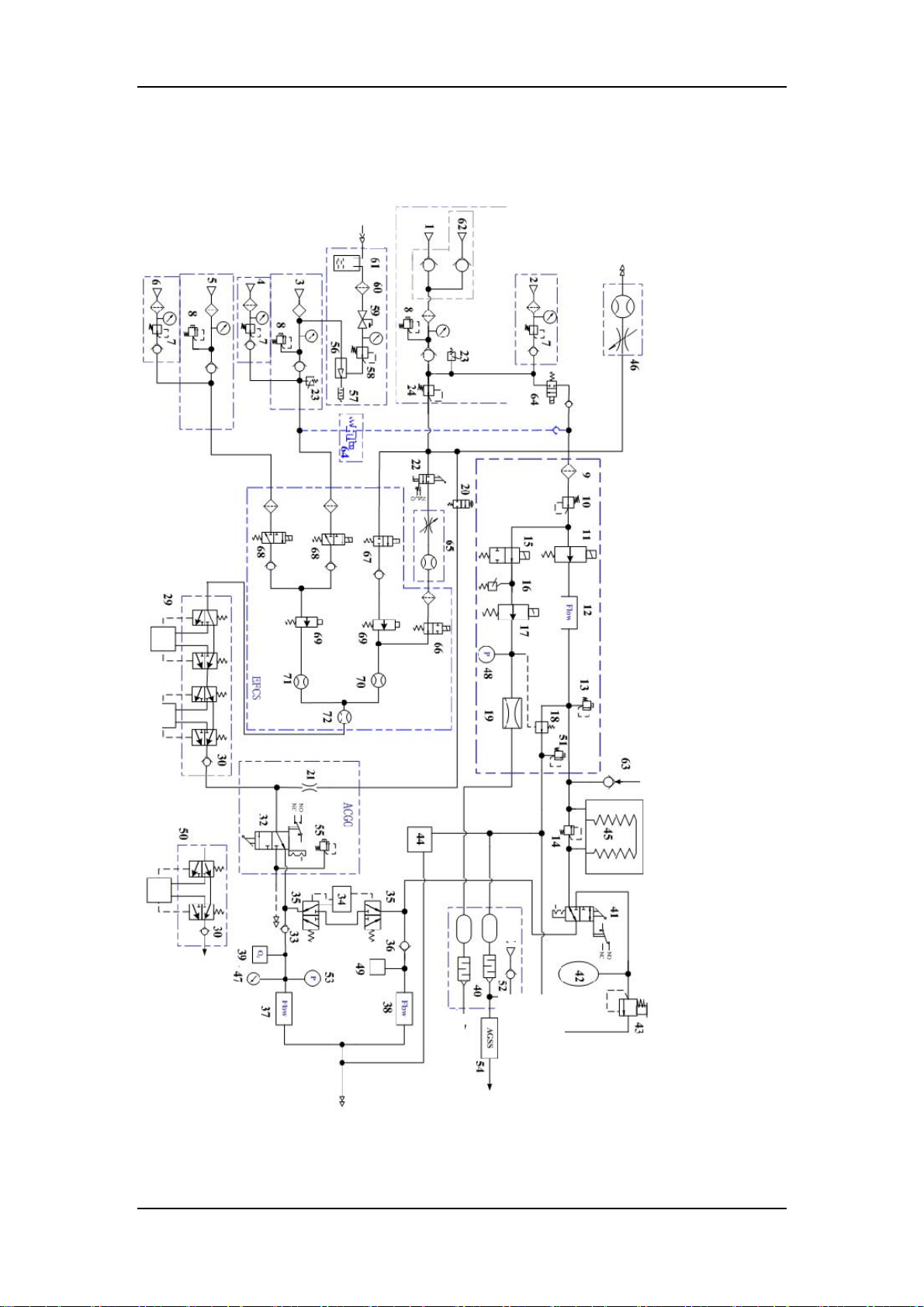
r
2.2 Pneumatic Part
2.2.1 Pneumatic Circuit Diagram
Patien
Backup O2 supply port
Vaporizer
Vaporizer
Air
Patient
Ai
system
Hospital treatment
2-45
Page 60

2.2.2 Pneumatic Components and Symbles
2.2.2.1 Pneumatic Components
The series numbers of components correspond with the number in the above pneumatic circuit
diagram.
SN Name SN Name
1 O2 P- Line 37 Inspiratory flow sensor
2 O2 cylinder 38 Expiratory flow sensor
3 Air P- Line 39 O2 sensor
4 Air cylinder 40 Scavenging reservoir and muffler
5 N2O P- Line 41 Manual/Auto switch
6 N2O cylinder 42 Manual bag
7 Regulator (0.4MPa) 43 APL valve
8 Pressure relief valve (0.758MPa) 44 Gas module
9 Filter 45 Bellows assembly
10 Regulator (0.2MPa) 46 Auxiliary O2 supply
11 Inlet gas flow regulator 47 Airway pressure gauge
12 Flow sensor (Venturi) 48 Pressure sensor
Mechanical overpressure valve
13
(100cmH2O)
14 Pop-Off valve 50 Single-vaporizer manifold
15 PEEP safety valve 51 Pressure relief valve (10cmH2O)
16 Pressure switch (125KPa) 52 Negative pressure valve (1cmH2O)
17 Proportional PEEP valve 53 Pressure sensor
18 Expiratory valve 54 AGSS
19 Pneumatic resistor 55 Pressure relief valve (11KPa)
20 O2 flush valve 56 Venturi negative pressure generator
21 Flow restrictor 57 Muffler
22 System switch 58 Adjustable negative pressure gauge
23 Pressure switch (0.2MPa) 59 Floating overfill protection valve
24 Regulator (0.2MPa) 60 Negative pressure suction filter
25 / 61 Liquid bottle
26 / 62 Backup oxygen supply connector
27 / 63 Free expiratory valve
28 / 64 Drive Gas Switch
29 Double-vaporizer manifold 65 Backup oxygen flowmeter
Check valve
30
/
31
ACGO selector switch
32
33 Inspiratory valve 69 Proportional valve
34 CO2 absorber 70 Oxygen flow sensor
35 BYPASS cut-off valve 71 Nitrous oxide and air flow sensor
36 Expiratory valve 72 Total flow sensor
Water collection cup
49
Two-position two-way switch valve
66
(NO)
Two-position two-way switch valv
67
(NC)
Two-position three-way switch valve
68
(NC)
2-46
Page 61
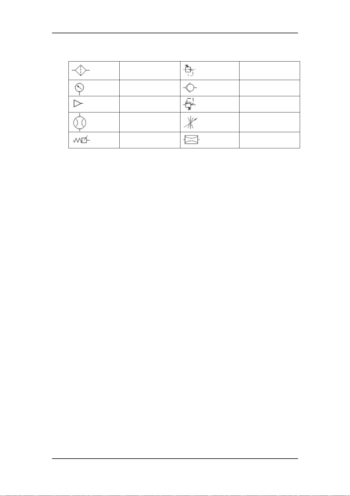
2.2.2.2 Key to Symbols
Filter
Pressure Gauge
Gas Supply
Connector
Flow Meter
Pressure Switch
Regulator
Check Valve
Pressure Relief Valve
Flow Control Valve
Flow Restrictor
2-47
Page 62
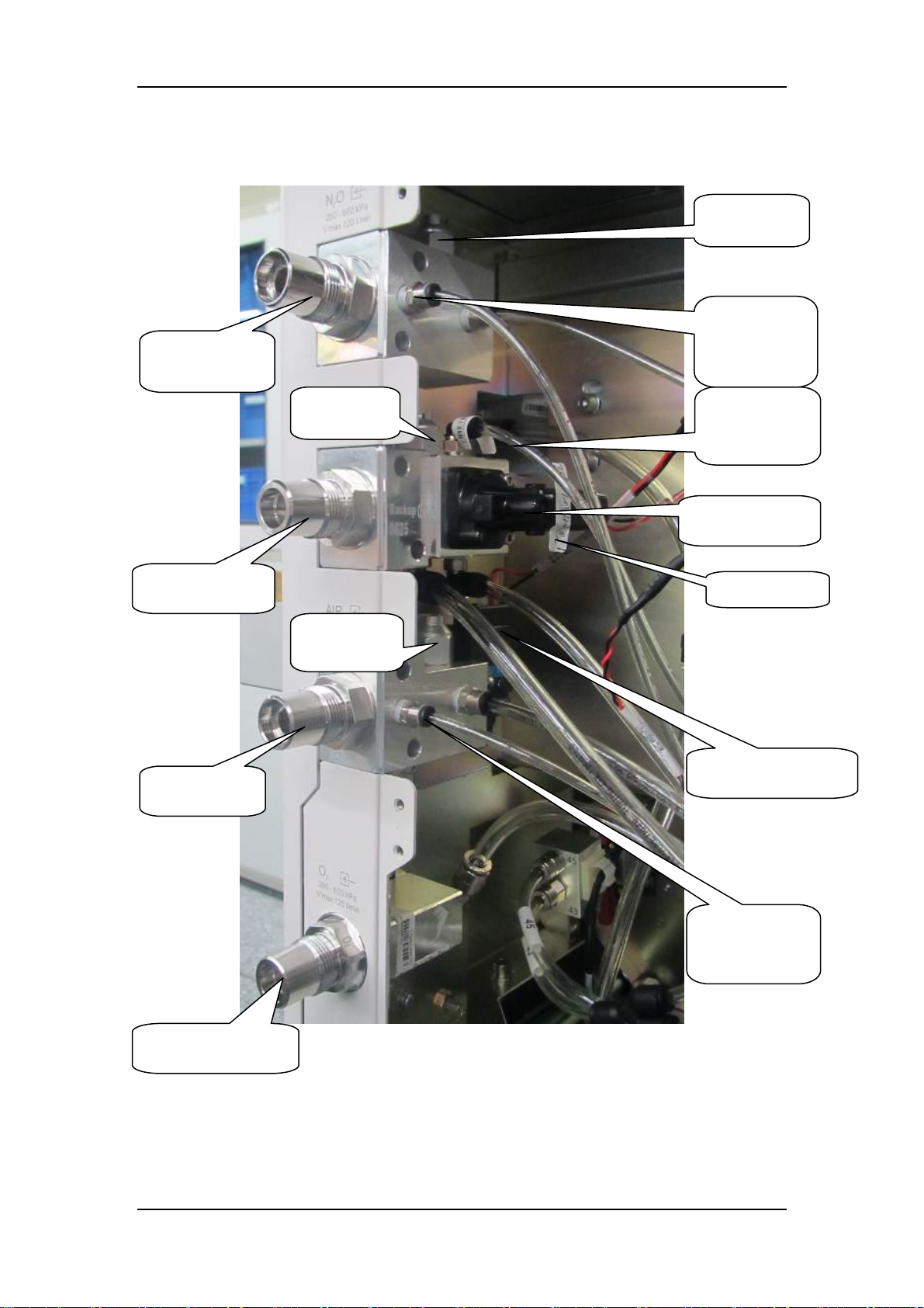
pply
pply
pply
pply
2.2.3 Gas Supplies
2.2.3.1 Pipeline Supply System
N2O pipeline
supply inlet
8 Pressure
relief valve
Pressure
sampling pipe
of N2O
su
O2 pipeline
inlet
su
Air pipeline
inlet
su
8 Pressure
relief valve
8 Pressure
relief valve
Pressure
sampling pipe
of O2 supply
23 Pressure
switch
24 Regulator
23 Pressure switch
Backup O2 pipeline
inlet
su
Pressure
sampling pipe
of air supply
2-48
Page 63
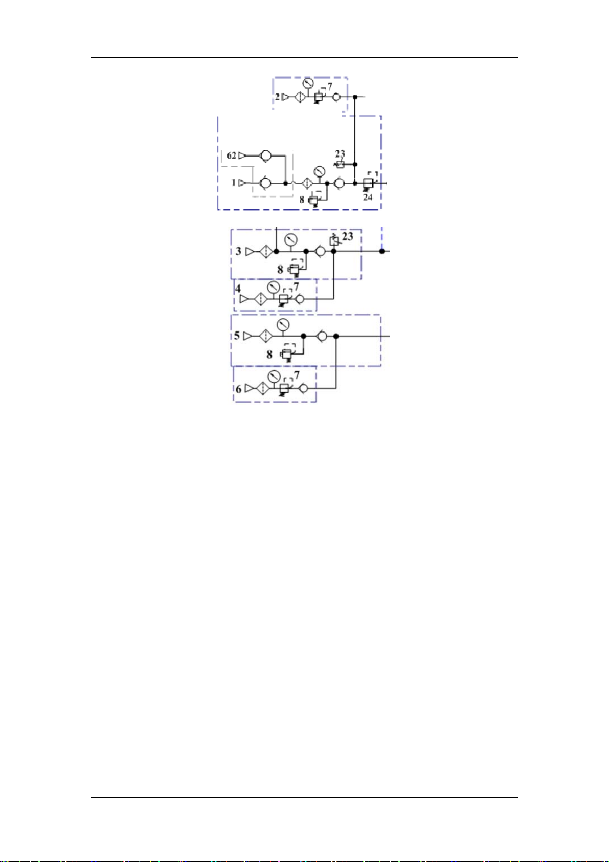
O2 pipeline
g
supply inlet
assembly
Backup O2 supply
(without backup cylinder)
Air pipeline
supply inlet
assembly
N2O pipeline
supply inlet
assembly
The above are three pipeline gas supplies, O2, N2O and Air, which functions to introduce the
external pipeline gases into the machine. Since the pressure of external gas is very high and the
external gas contains foreign substance, pressure reducing valves, filters and pressure relief valves
are available in the supply gas circuit. Also, check valves are equipped in the supply gas circuit to
prevent gas from flowing back into the pipeline or cylinder. The pipeline pressure ranges between
280 and 600 kPa. Pressure relief valve 8 functions to prevent the supply gas pressure from being
too high. It releases excess gas when gas pressure exceeds 758 kPa. Each connector is clearly
marked and designed to prevent misconnection. All connectors have filters and check valves.
Color coded gauges show the pipeline and cylinder pressures. Supply O2 is outputted after O2
pressure is decreased below 200 kPa through regulator 24. Pressure switch 23 monitors the O2 and
Air supply pressure. When O2 and Air supply pressure is less than approximately 200 kPa, the
ventilator gives the alarm of O2 or Air supply failure.
Drive
Needle valve
Needle valve
as
2-49
Page 64
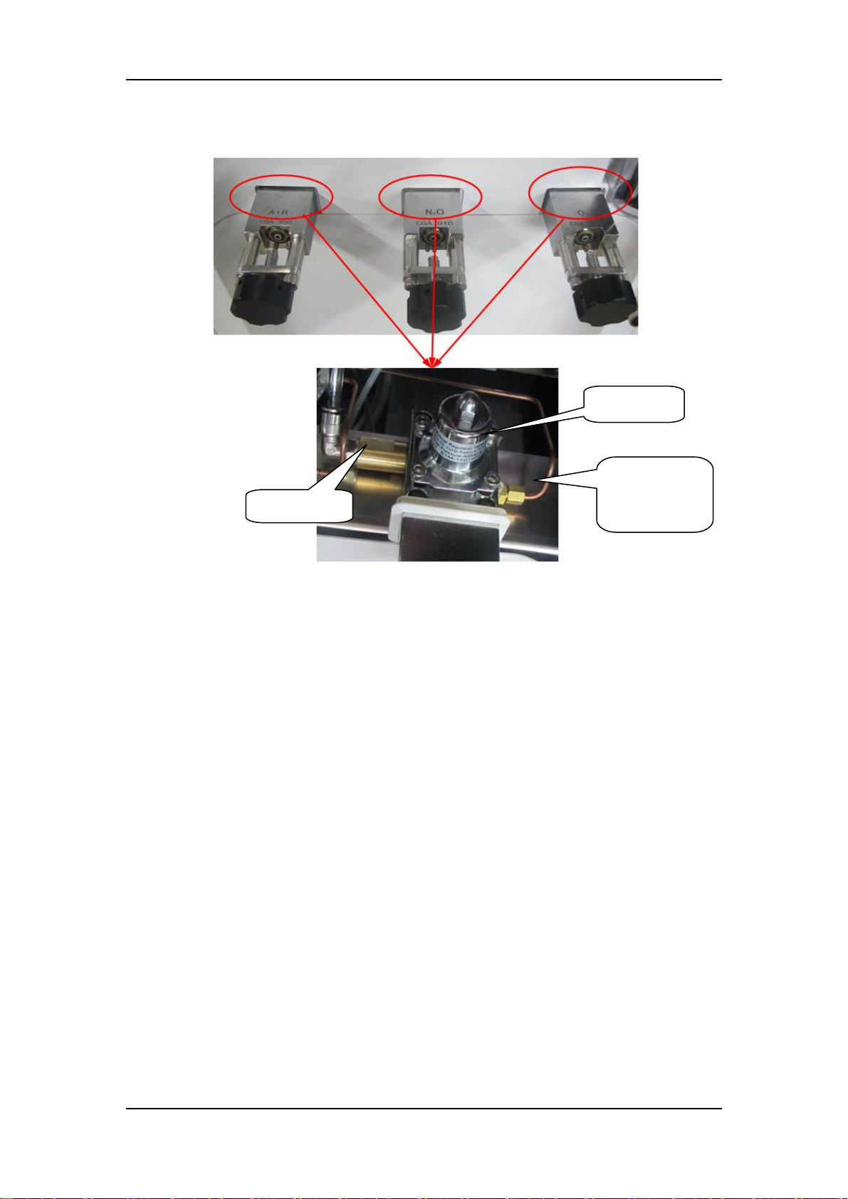
2.2.3.2 Backup Supply System
Check valve
7 Regulator
Pressure
sampling pipe
of cylinder
The above are three inlet assemblies of backup cylinder supplies, O2, N2O and Air, which
functions to introduce the external cylinder gases into the machine. Cylinder gas supplies, which
, Air and N2O, go into the system through cylinder connectors 2, 4 and 6 respectively. The
are O
2
O2, Air and N2O cylinder pressures are 6.9–15 MPa, 6.9–15 MPa and 4.2–6 MPa respectively,
which are decreased to approximately 400 kPa through pressure relief valve 7. Each connector is
clearly marked and designed to prevent misinstallation. All connectors have filters and check
valves. Color coded gauges show the pipeline and cylinder pressures. Pressure relief valve 8
functions to prevent the supply gas pressure from being too high. It releases excess gas when gas
pressure exceeds 758 kPa. Supply O2 is outputted after O2 pressure is decreased below 200 kPa
through regulator 24. Pressure switch 23 monitors the O2 and Air supply pressure. When O2 and
Air supply pressure is less than approximately 200 kPa, the ventilator gives the alarm of O2 or Air
supply failure.
2-50
Page 65
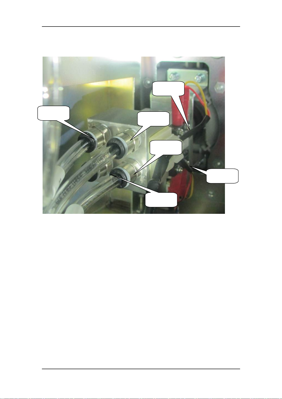
2.2.4 Anesthetic Gas Delivery System
2.2.4.1 System Switch Assembly
inching
Air inlet
O2 inlet
O2 outlet
inching
Air outlet
There are two kinds of systwm switch, single O2 system switch, and O2 and Air system switch.
The above figure shows the O2 and Air system switch. Supply gases of Air and O2 go into system
switch 22, and then needle valve. For single O2 system switch, only O2 goes into system and then
needle valve. System switch has an electrical outlet which controls the power-on status of the
system. When the system switch is turned on, O2 and Air enter theneedle valve and the system is
powered on simultaneously. The anesthetic ventilator starts to monitor the status of the system.
When the system switch is turned off, O2 and Air cannot enter the needle valve and the system is
powered off.
2-51
Page 66
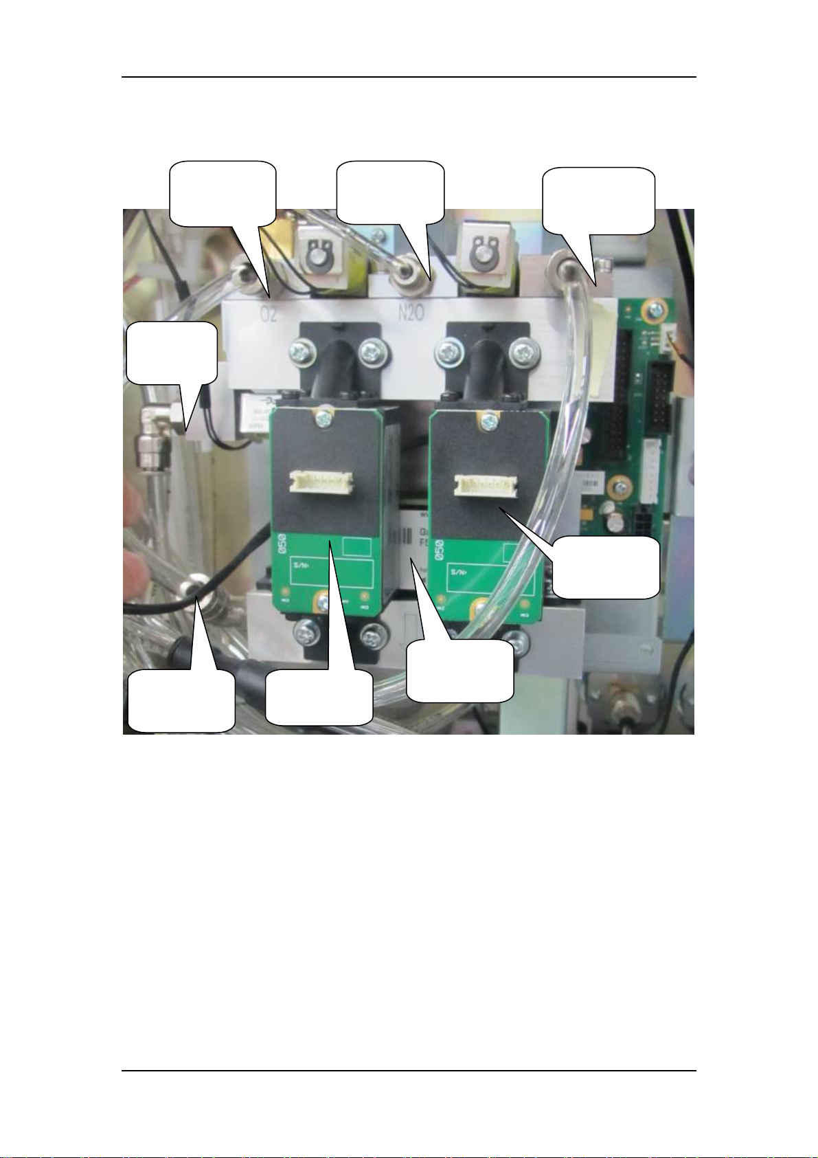
pply
)
r
2.2.4.2 Electronic Flow Control System-EFCS
From
backup O2
flowmete
O2 (from the
O2 supply)
N2O (from
the N2O
su
Air (from the
air supply)
Balance gas
sensor
Total flow
To the
vaporizer
manifold
The EFCS uses solenoid proportional valves to control the oxygen, air and nitrous oxide flow and
monitor the actual flow, and provides feedback to the flow control unit. After passing three
independent check valves, the gases of the three limbs are mixed at the rear end of the assembly
and output. The O2-N2O ratio is fully controlled by a software algorithm. The system display
outputs the monitored values of parameters such as the limb flow and O2-N2O ratio.
The above figure shows the pneumatic block structure of the EFCS. The three gases, after being
regulated, goes through the proportional valves, through limb sensors, through the gas mixing
chamber, and into the three-way valve. Then, the gas mixture returns to the total flow sensor and
finally output to the mechanical float flow meter.
O2 sensor
sensor
2-52
Page 67
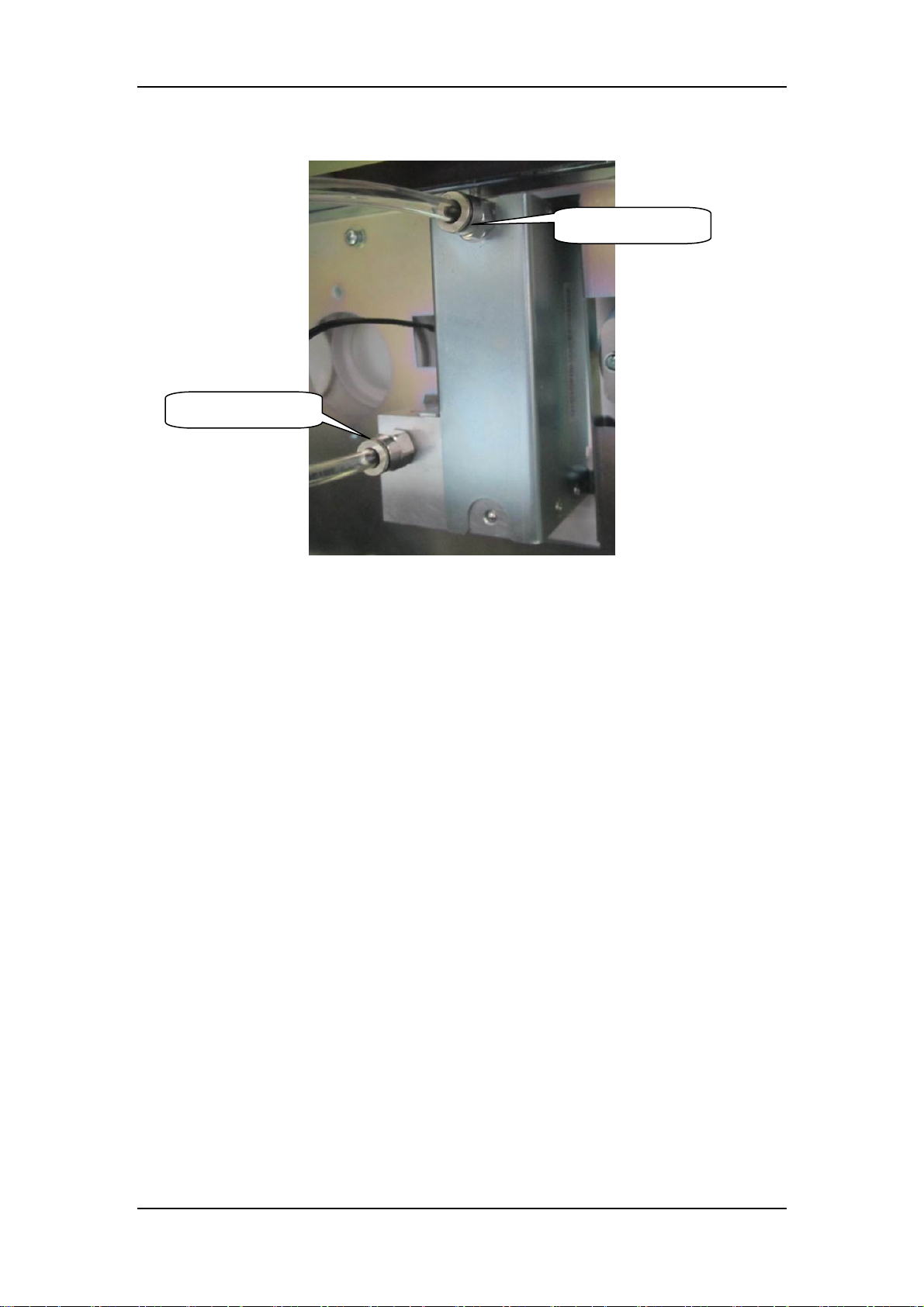
2.2.4.3 Flow Control System-BFCS
O2 inlet
O2 outlet
BFCS offers 200KPa O2 displayed through the glass tube electronic flowmeter and delivered to
patients after passed through the system switch. Turning flow controls counter-clockwise increases
the flow and clockwise decreases the flow, with the basic flow rate of 0.75-1.25L/min.
2-53
Page 68
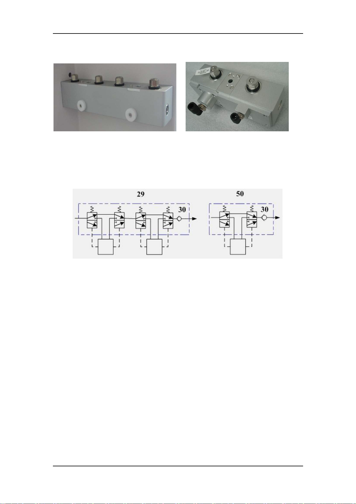
2.2.4.4 Vaporizer Manifold
Double vaporizer manifold Single vaporizer manifold
There are two kinds of vaporizer manifold, double vaporizer manifold and single vaporizer
manifold. The anesthetic gas delivery device (vaporizer) is connected to the anesthetic gas
delivery system. The mixed gas of N2O, O2 and Air go into the device and the fresh gas
containing these three gases and anesthetic agent is finally outputted to the ACGO assembly.
The following diagram shows the pneumatic circuit of anesthetic gas delivery device (vaporizer).
Double-vaporizer manifold 29 is integrated with check valve 30 which prevents flushing O2 and
fresh gas from flowing back to the vaporizer. When a double-vaporizer manifold is used,
Selectatec mounting with interlocking function can prevent the user from turning on two
vaporizers simultaneously.
Vaporizer
Vaporizer
2-54
Page 69
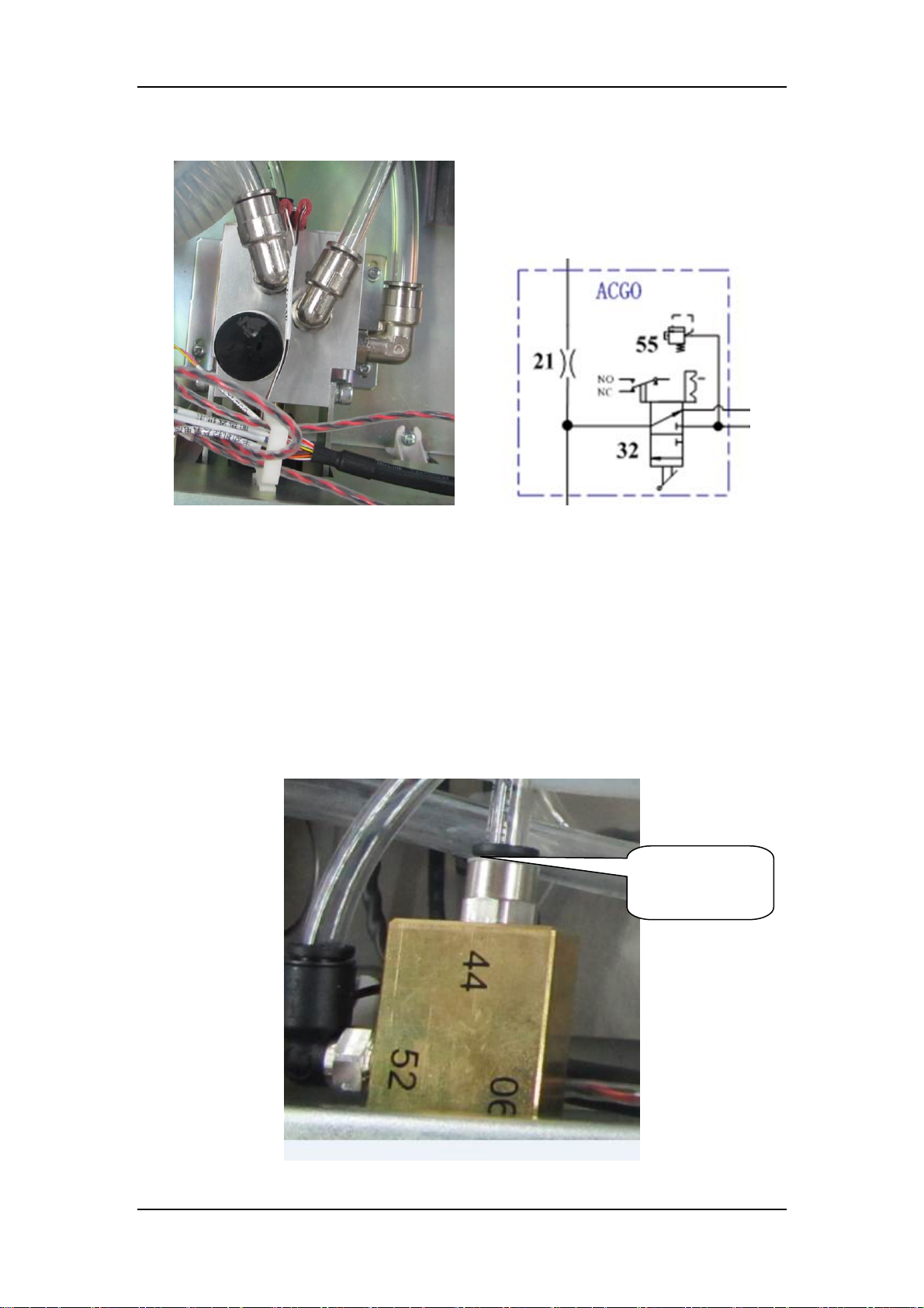
2.2.4.5 ACGO Assembly
Enter breathing
system
ACGO outlet
The above picture shows the ACGO assembly. The ACGO assembly includes flow restrictor 21,
pressure relief valve 31, and pressure relief valve 55. Inputted O2 and fresh gas are mixed and
enter the ACGO. Pressure relief valve 31 at the front restricts the pressure of inputed O2 and also
that of the fresh gas not to exceed 37.9 kPa. Pressure relief valve 55 at the back ensures that the
pressure of the gas outputted to the ACGO does not exceed 12.5 kPa. Flushing O2 and fresh gas
are mixed through the three-way valve and enter the ACGO. The outputs include fresh gas
provided for the breathing system (when ACGO is turned off) and that provided for the patient
(when ACGO is turned on). Pressure relief valve 31 at the front restricts the pressure of flushing
O2 and also that of the fresh gas not to exceed 38 kPa (approximate value). Pressure relief valve
55 at the back ensures that the pressure of the gas outputted to the ACGO does not exceed 12.5
kPa.
2.2.4.6 O2 Flush Button Assembly
O2 inlet
2-55
Page 70
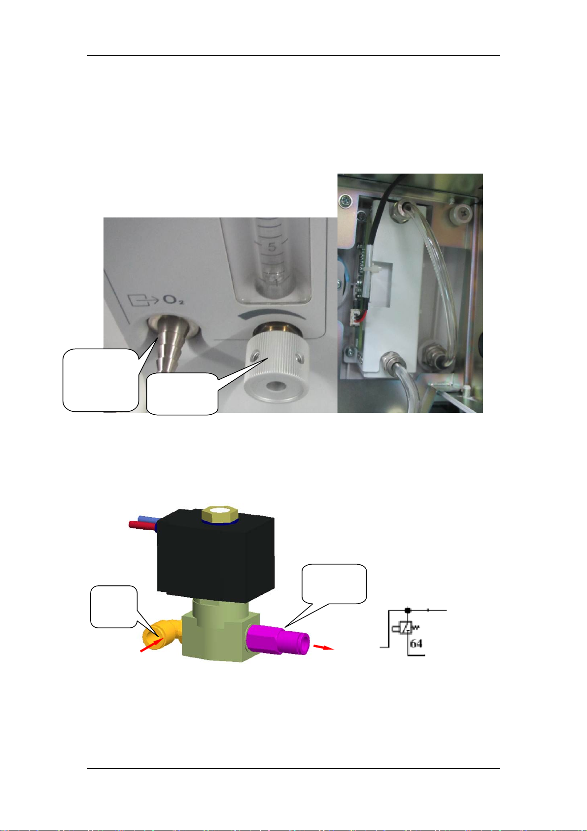
The above picture shows the O2 flush button assembly. When O2 flush valve 20 is depressed, O2
rushes into the pneumatic circuit which is cut off when this valve is released. The O2 supply gas at
0.2 MPa after regulated goes through the O2 flush valve, the ACGO assembly, and into the
breathing system. The O2 flush button assembly is not affected by the system switch. Flushing O2
can be performed as long as O2 supply is normal. The O2 flush valve has a slide valve structure
inside which ensures automatic reset each time the valve is depressed and released via the spring.
2.2.4.7 Auxiliary Supply Assembly
O2 supply
inlet
assembly
For auxiliary supply assembly, O2 of 200KPa goes into the patient, with flow controlled by
regulator 24 and displayed by a glasstube float flowmeter. The flow range adjusted is from 0 to 15
L/min. Turning the flow control counter-clockwise increases the flow and clockwise decreases the
flow.
Adjusting
knob
2.2.4.8 Drive Gas Switch Assembly
Gas outlet
Gas
inlet
Main drive
gas
The core component of drive gas switch assembly (64) is a pneumatically controlled two-way
solenoidvalve, which is installed on Air limb or O2 limb to realize a main drive gas and a backup
drive gas. When the pressure of main drive gas limb is lower than 125 kPa, the alarm of pressure
switch on the exhalation valve is triggered, and a dialog of drive gas switch appears on the screen
to note the operater to turn on the drigve gas switch and enable backup drive gas.
Enter bellow
Bckup drive
gas
2-56
Page 71
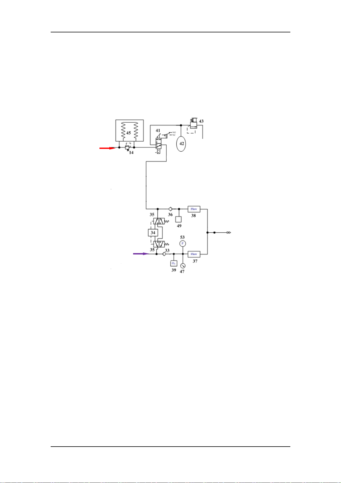
2.2.5 Breathing System
2.2.5.1 Overview
The breathing system provides a closed loop for the anesthetic gas. The CO2 in the patient’s
expired gas can be inspired in the inspiration phase to maintain the temperature and humidity
conditions of the patient’s exhaled gas. During inspiration, the drive gas depresses the bag inside
the bellows or the doctor presses manual bag to force the inside gas to enter the patient’s lung.
During expiration, the patient’s expired gas goes into the bag inside the bellows or manual bag.
Sodalime canister 34 absorbs CO2 the patient expires. The following diagram shows the
pneumatic circuit of breathing system.
AGSS
Drive gas
Patient
Fresh gas
Manual and mechanical ventilation modes are selected through the manual/auto switch 41. When
manual ventilation is selected, the doctor presses manual bag 42 to supply gas for the breathing
system. APL valve 43 is used to adjust the pressure inside the pneumatic circuit in case of manual
ventilation. When mechanical ventilation is selected, the ventilator starts to work. It controls the
drive gas to depress the folding bag inside bellows 45 and supply gas for the breathing system as
per the selected ventilation mode.
Breathing system is connected to the anesthesia machine main unit through the circuit adapter. Its
tubes are all built in except the tube connected to the patient and the O2 cell cable, as shown
below.
2-57
Page 72
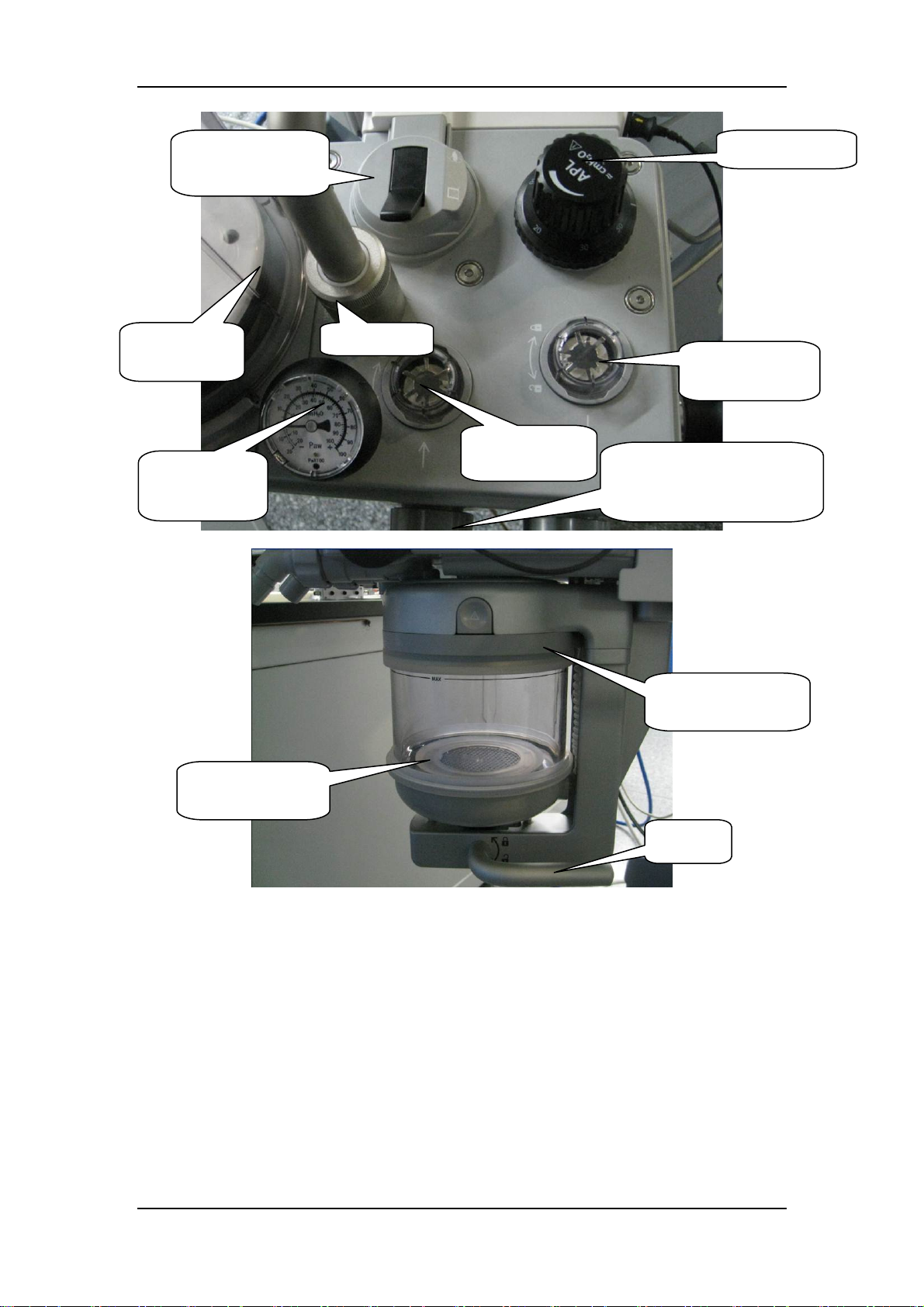
41. Manual/auto
switch
45. Bellows
assembly
47. Airway
pressure gauge
Bag arm
36. Expiratory
valve
43. APL valve
33. Inspiratory
valve
Patient connection (built-in
inspiratory and expiratory
flow sensors 37 and 38)
35. Built-in
BYPASS valve
34. CO2
absorbent canister
Handle
In case of mechanical ventilation, during inspiration, gas flows through manual/auto switch 41,
BYPASS valve 35 or sodalime canister 34, inspiratory valve 33, O2 sensor 39, airway pressure
gauge 47, and inspiratory flow sensor 37 to the patient. During expiration, gas flows through
expiratory flow sensor 38, expiratory valve 36 and manual/auto switch 41 to the folding bag or
manual bag. Airway pressure is monitored by pressure sensor 53.
The water generated by condensation is collected in the water collection cup on the bottom of
breathing system.
The breathing system is easily disassembled and is autoclavable at 134℃.
2-58
Page 73
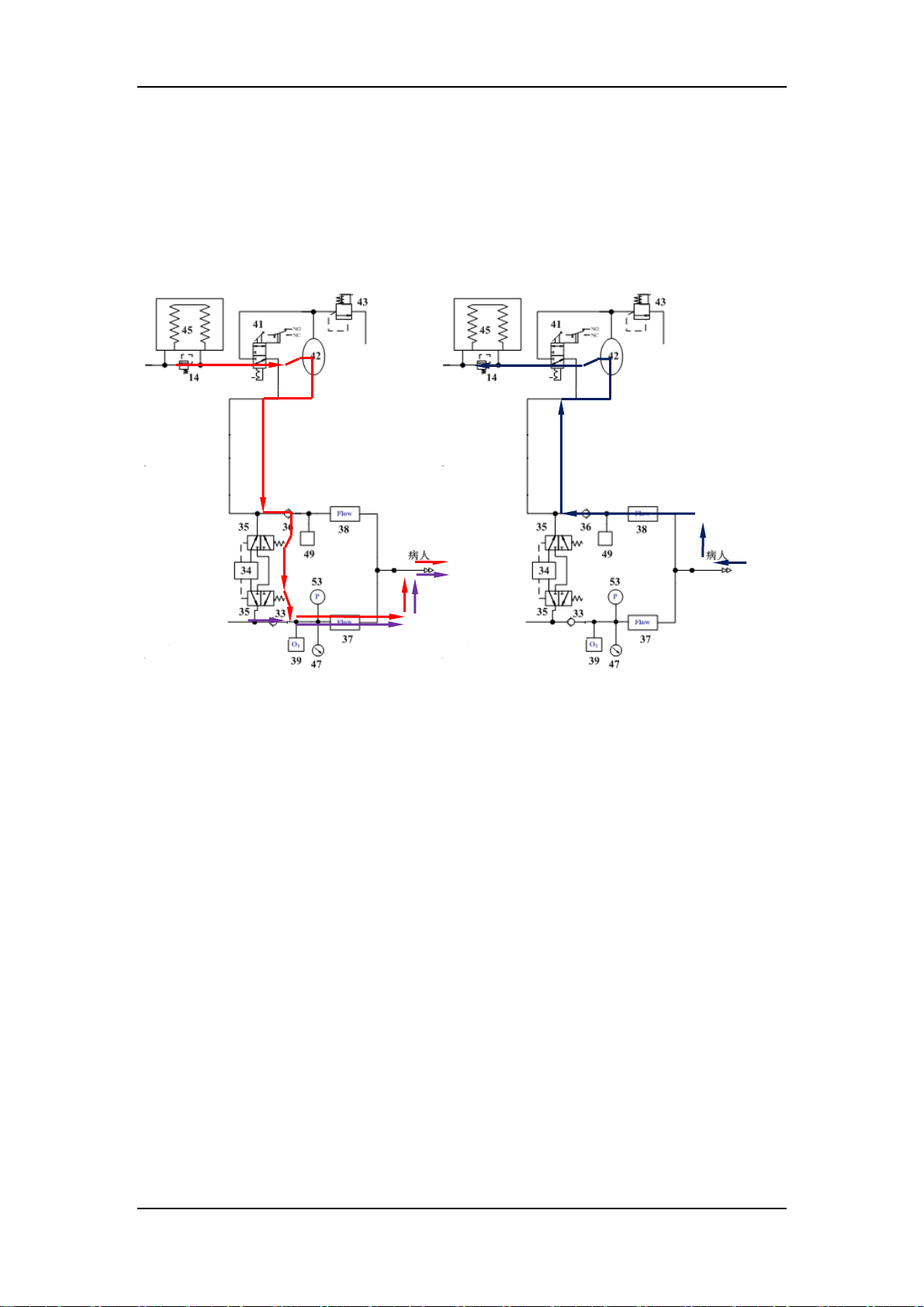
2.2.5.2 Mechanical Ventilation
The breathing system is in mechanical ventilation by switching manual/auto switch to auto
position, as shown in the following figures. During inspiration, gas in the bellow flows through
manual/auto switch 41, BYPASS valve 35 or sodalime canister 34, and then is mixed with the
fresh gas and continue to flow through inspiratory valve 33, O2 sensor 39, airway pressure gauge
47, and inspiratory flow sensor 37 to the patient. During expiration, gas breathed out by the patient
flows through expiratory flow sensor 38, expiratory valve 36 and manual/auto switch 41 to the
below, and then enter the anesthetic gas scavenging system (AGSS).
Drive gas
Fresh gas
A. Mechanical inspiration mode B. Mechanical expiration mode
To AGSS
Gas breathed out
by the patient
Patient Patient
2.2.5.3 Manual Ventilation
The breathing system is in manual ventilation by switching manual/auto switch to manual position,
as shown in the following figures. During inspiration, drive gas flows through manual/auto switch
41, BYPASS valve 35 or sodalime canister 34, and then is mixed with the fresh gas and continue
to flow through inspiratory valve 33, O2 sensor 39, airway pressure gauge 47, and inspiratory flow
sensor 37 to the patient, by pressing manual bag. During expiration, gas breathed out by the
patient flows through expiratory flow sensor 38, expiratory valve 36 and manual/auto switch 41 to
the APL valve 43, and then enter the anesthetic gas scavenging system (AGSS).
2-59
Page 74
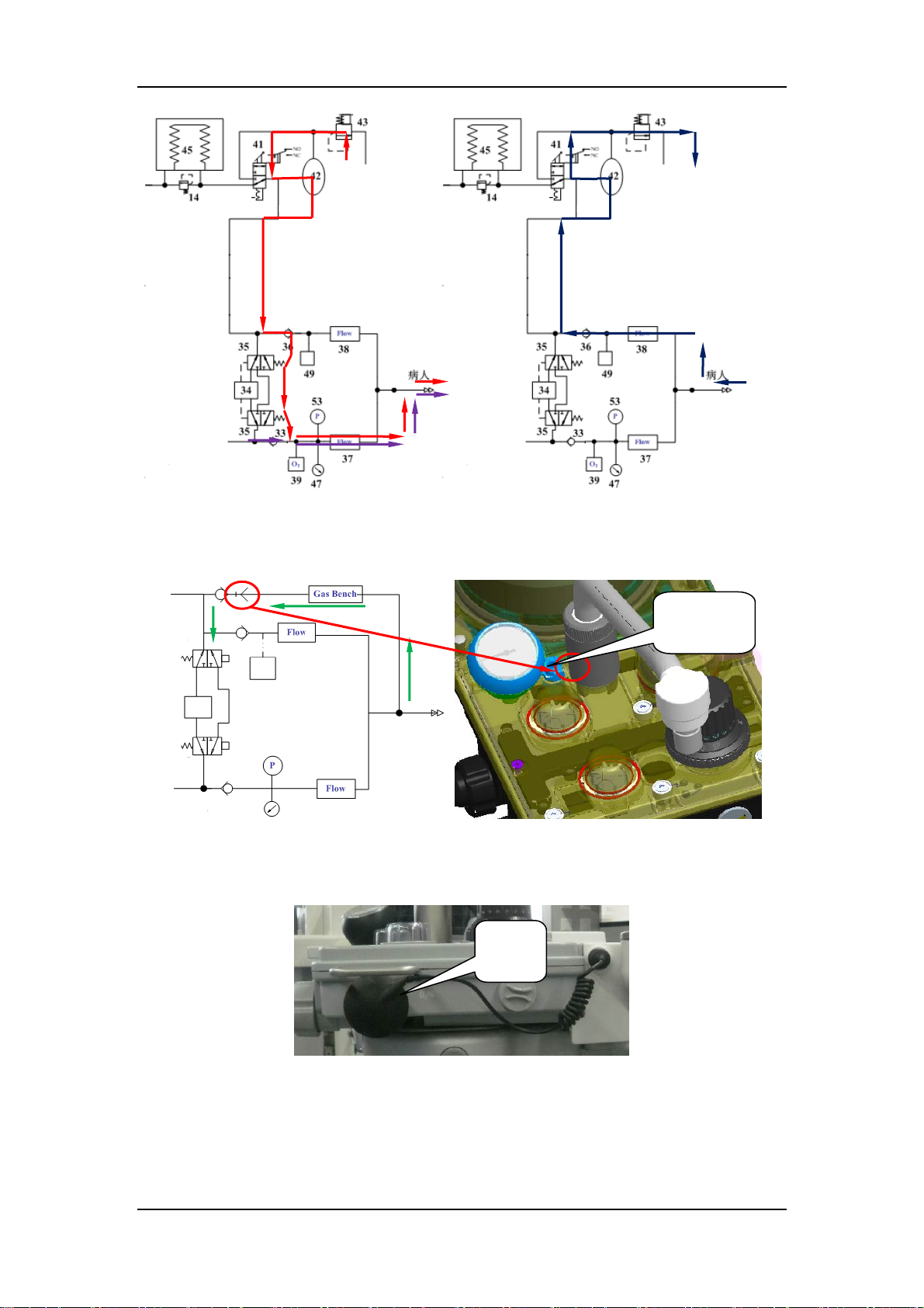
Drive gas
p
To AGSS
Gas breathed out by the
atient
A. Manual inspiration mode B. Manual expiration mode
2.2.5.4 Gas Bench
CPC
connector
The sample gas, collected by AG module from the patient end, reenters to the breathing circuit
through the CPC connector with self closing function, shown as the above figure.
2.2.5.5 O2 Sensor
O2
sensor
O2 sensor, installed on the inspiration limb of the breathing circuit, monitors the O2 concentration
of the inspiration limb, shown as the above figure. If the O2 concentration of inspiration limb is
too low, an alarm will be triggered.
2-60
Page 75
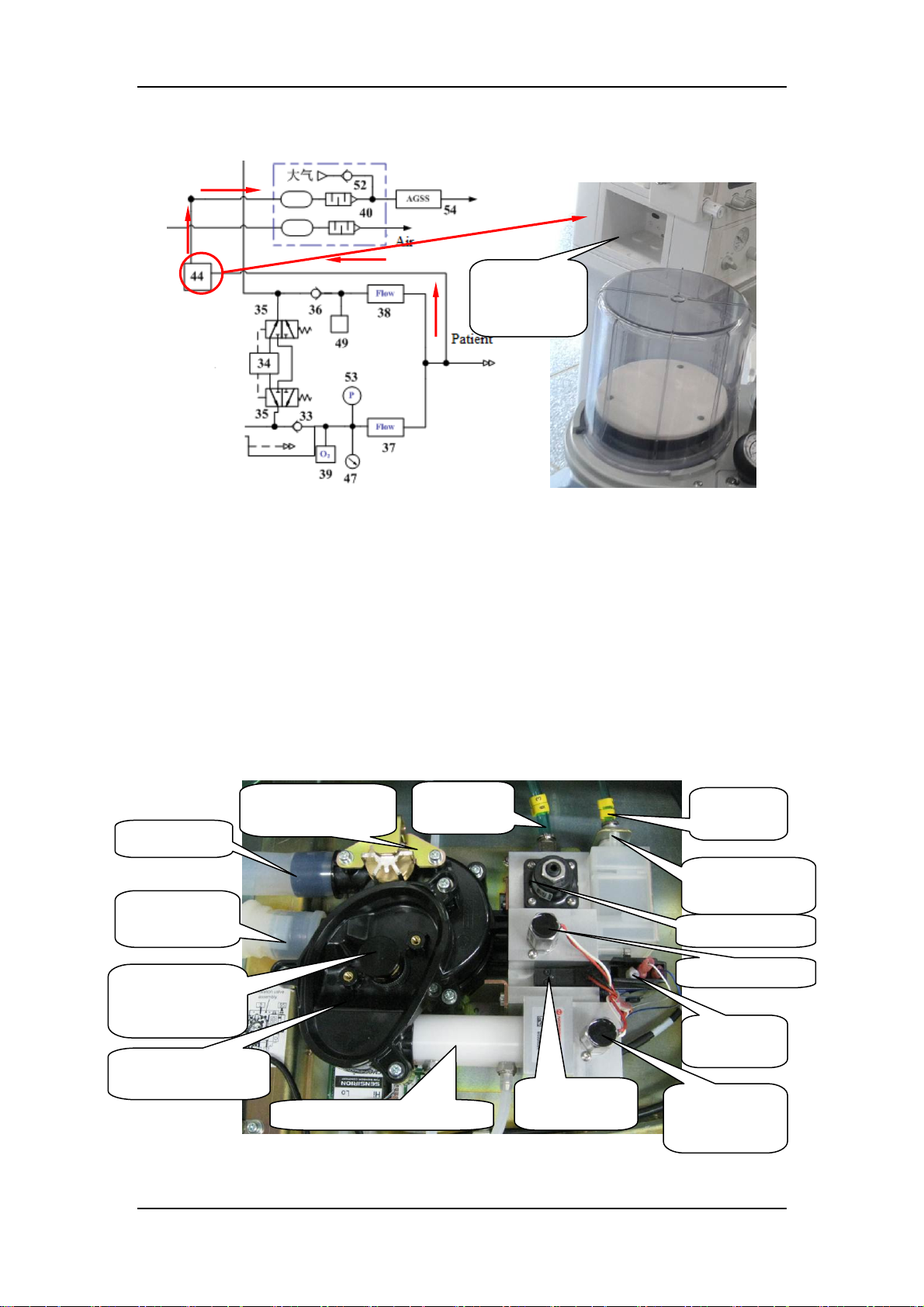
p
p
y
2.2.5.6 Anesthesia Calculation Module (If Available)
AG module
installation
position
Anesthesia calculation module (44, AG module), collecting the sample gas from patient, monitors
and calculates anesthesia concentration and CO2 concentration. When the anesthesia
concentration or CO2 concentration of the patient end is too high, an alarm will be triggered.
2.2.6 Pneumatically-Controlled Module of Anesthetic
Ventilator
The pneumatically-controlled module of the anesthetic ventilator provides drive gas for the patient
to breathe. O2 (or AIR) from the gas supply inlet assembly enters the anesthetic ventilator and is
output in three pathways: drive gas entering the breathing system, drive gas discharged through
the AGSS outlet, and drive gas discharged through the PEEP outlet. The ventilator controls drive
gas flow to implement various ventilation modes and prevent excessively high pressure inside the
pneumatic circuit from injuring the patient. The following figure shows the gas flow and
components.
Drive gas
ort
inlet
PEEP
outlet
19. Pneumatic
resistor
10. Regulator
ort
Exhaust port
Drive gas
outlet
51. Pressure relief
valve (10 cmH
2
O)
13.11kPa
Pressure relief
valve
18. Expiratory
valve
12. Differential manometer
2-61
15.PEEP
valve
safet
17. PEEP valve
16.Pressure
switch
11. Solenoid
proportional
valve
Page 76
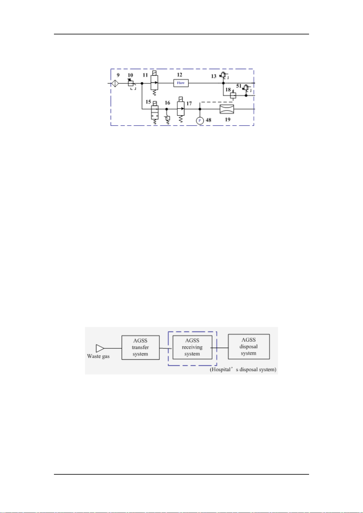
The following figure shows the pneumatic circuit diagram of the pneumatically-controlled module
of anesthetic ventilator.
Enter the bellow
Drive gas
assembly
Enter gas reservoir
As shown in the above figure, in the drive gas limb, the filter 9 filters drive gas again. The
regulator 10 regulates pressure (about 0.2 MPa) inside the pneumatic circuit. The proportional
solenoid valve 11 controls thedrive gas flow. The drive gas goes through the flow sensor 12 of
differential pressure type that monitors drive gas flow. The mechanical overpressure valve 13
ensures that the pressure in the drive gas circuit does not exceed the safety pressure. It releases
excess gas when gas pressure exceeds 11 kPa (110 cm H2O). The drive gas enters the bellow
through the exhalation valve 18. During expiration, the drive gas in the bellow goes out through
theis valve.
In PPEP limb, the PEEP function is performed through the expiratory valve. When PPEP valve 17
opens, gas is bled from the pneumatic resistor 19, forming relatively stable pressure in the
pneumatic circuit from PEEP valve 17 to the pneumatic resistor 19. Such pressure is exerted on
the membrane of the expiratory valve 18 to form PEEP.
To prevent excessively high pressure inside the pneumatic circuit from injuring the patient and
damaging the equipment, the pressure relief valve 15, which is a solenoid on-off valve, is placed
before the gas pathway of the expiratory valve. When the drive gas pressure is less than 125 kPa,
an alarm is triggered by the pressure switch 16. The pressure sensor 48 monitors the pressure at
the expiratory valve which is closed. The mechanical pressure relief valve 51 ensures that the tube
pressure after the expiratory valve is less than 10 cm H2O in expiration phase.
2.2.7 Anesthetic Gas Scavenging System
The AGSS is composed of the AGSS transfer system, the AGSS receiving system, and the AGSS
disposal system. Waste gas goes from the exhaust port of the anesthesia machine through the
AGSS transfer system and the AGSS receiving system to the hospital's waste gas disposal system
(AGSS disposal system), as shown in the following figure.
The following diagram shows the operational theory of the AGSS. The throttling holes reduce the
effect of negative pressure at the AGSS outlet onto the flow at the entrance. The float helps the
user to learn if the AGSS works normally. When the upper edge of the float is between the MAX
and MIN marks of the sight glass, it indicates that the AGSS is in normal working status. The filter
filters foreign substance to prevent the disposal system from being occluded. The gas reservoir is
connected to the air through pressure compensation openings. When positive or negative pressure
occurs inside the gas reservoir, gas is inputted or outputted to ensure pressure balance inside the
system.
2-62
Page 77
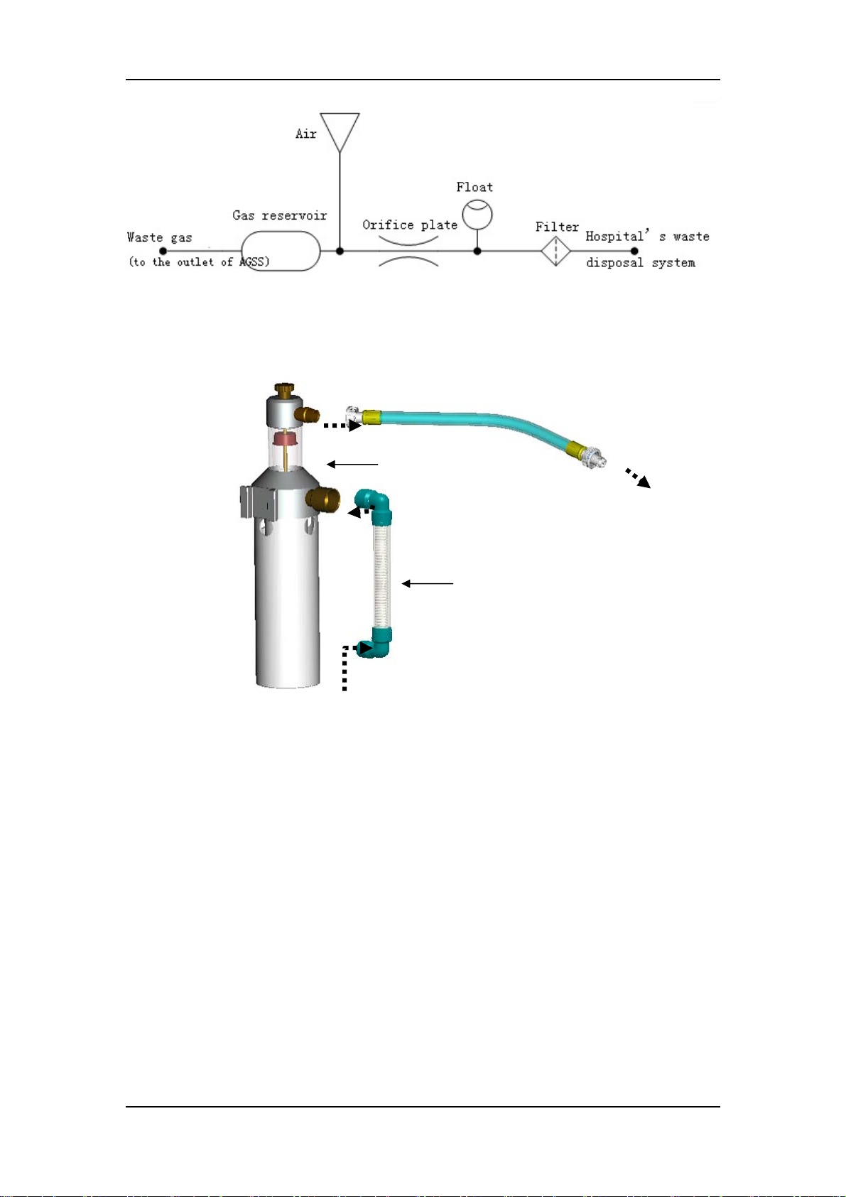
The AGSS transfer system is a clear tube with 30 mm purple conical connectors at both ends, a
female 30 mm conical connector as the inlet and a male 30 mm conical connector as the outlet.
The transfer system is connected to the receiving system through the male 30 mm conical
connector. The following figure shows the AGSS structure and the connections between the AGSS
transfer system, receiving system, and disposal system.
Hose of receiving system
Main part of transfer and
receiving system
To the disposal system
Hose of transfer system
To the waste gas exhaust port of the
anesthesia machine
2.2.8 Breathing System Heater
The breathing system heater of this anesthesia machine provides dual overheat protection for
software and hardware. The heater can change its operating mode automatically according to the
ambient temperature.
2.2.9 Ventilator Pneumatic - O2 Drive Gas
Oxygen or air, switching by the drive gas switch, is the drive gas for the ventilator. In addition to
the flow meter block, a high pressure regulator reduces the supply pressure of the drive gas for the
ventilator to 200 kPa (29 psi).
The drive pressure regulator is placed in front of the proportional valve that generates the drive
gas flow during the inspiratory phase. This flow is injected into the space between the bellows and
the bellows housing.
2-63
Page 78
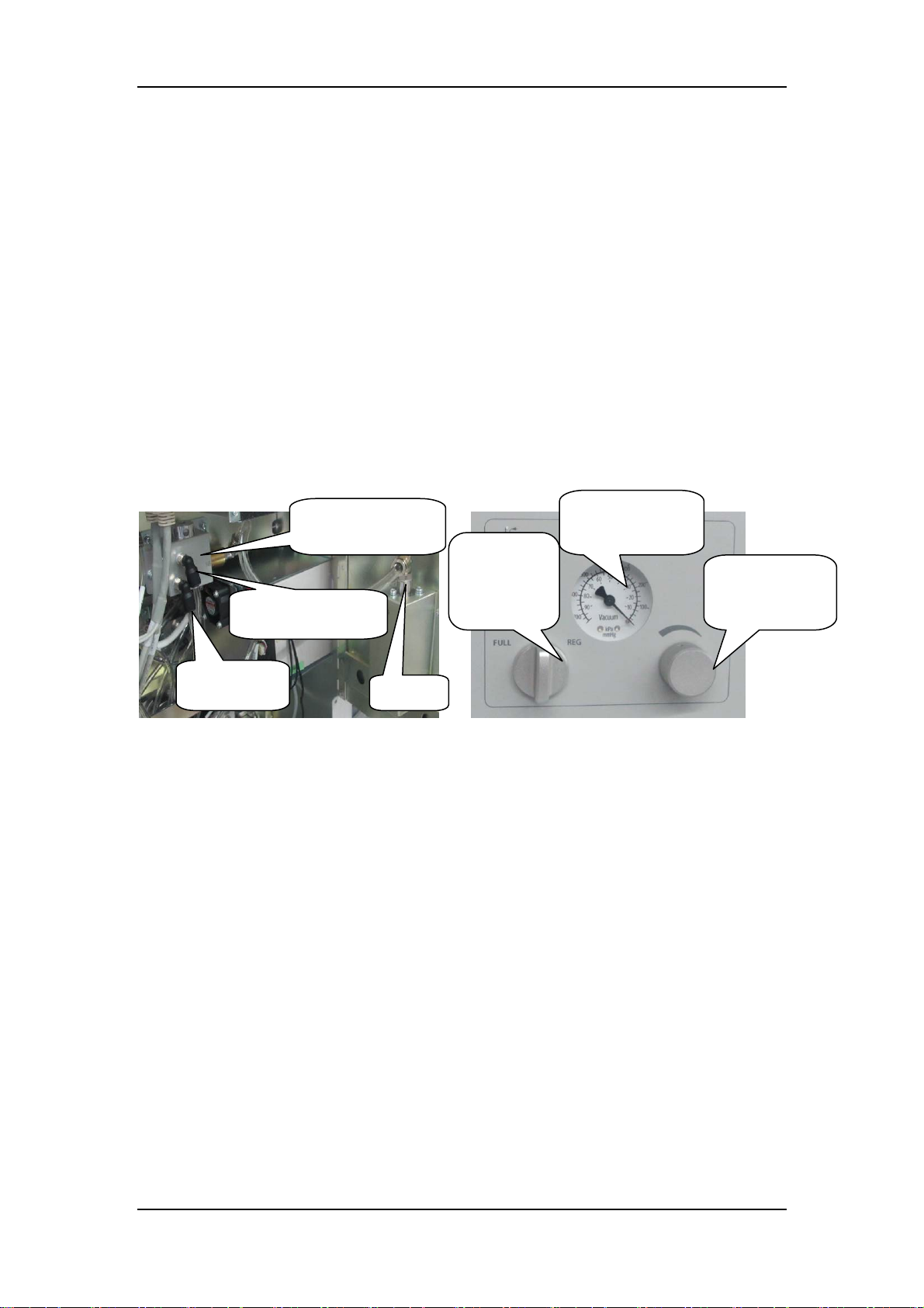
2.2.10 Drive Pressure - High Pressure Regulator (200 kPa, 29
psi)
The drive pressure regulator stabilizes the supply pressure upon the proportional valve.
The flow generated by the proportional valve is therefore independent of pressure variations at the
supply.
Setting the drive pressure regulator at 200 kPa (29 psi) allows for a maximum of inspiratory flow
of 110 L/min at the ventilator.
2.2.11 Drive Gas Assembly
The drive gas assembly comprises the inspiratory circuit and PEEP circuit. The gas flow of the
inspiratory circuit goes through the inspiratory valve, which generates a gas flow of 0 to 110
L/min. The gas flow of the PEEP circuit goes through the PEEP valve, which also generates gas
pressure of 3 to 30 cm H2O. Both the PEEP and inspiratory valves are proportional solenoid
valves controlled by the valve drive board.
2.2.12 Negative Pressure Suction System
Negative pressure
outlet
Negative pressure
generator
Negative
pressure
selecting
knob
Negative
pressure gauge
Negative
pressure
adjusting knob
Drive gas
inlet
This negative pressure suction system is a Venturi negative pressure suction system. Negative
pressure is produced by the Venturi pipe in the negative pressure generator drive d by Air. The
negative pressure value is displayed and adjusted as needed by the negative pressure control pamel
assembly. Drive gas goes through the negative pressure generator, and then is discharged from the
muffler assembly to the air. Negative pressure control pamel realizes the on-off controlling and
adjusting of the negative pressure source.
Muffler
2-64
Page 79

3 Installation Guide
3.1 Preparation
Before installation, contact the consumer and tell him/her to provide the following materials. The
customer is responsible for supplying these materials. Missing items may result in delays,
incomplete installations, and/or additional service visits.
Gas supply hose connector.
O2 cylinder, N2O cylinder, and Air cylinder in compliance with the configuration
standard.
Anesthetic vaporizer and adapter (if not purchased together with the anesthesia system)
Anesthetic agent
Loose fill or Pre-pak CO2 absorbent
Effective O2, N2O, and Air gas sources (280 to 600kPa (40 to 87psi))
Dropdown hoses for ceiling mounted medical gas equipment, compatible with
quick-disconnect hoses ( if not purchased together with the anesthesia system)
3.2 Assembly
NOTE
After the flow sensors are calibrated, the anesthesia machine must be used together
with the breathing system module. If the breathing system module is removed,
make sure that it is re-installed onto the original anesthesia machine. If other
breathing system module is to be installed, the flow sensor must be re-calibrated
(please refer to 7.3.2Flow calibration (Service)).
3-1
Page 80
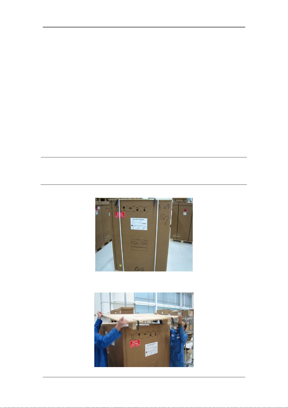
3.2.1 Unpacking and Setup
1. After receiving this device, check the packing box for damage immediately.
a. If there is no damage and the anti-tilt label on the packing box does not turn red, sign the
name and date on the bill of lading or air waybill to indicate that the anesthesia machine
has been received safely.
b. If there is damage or the anti-tilt label on the packing box is not in good condition (red),
describe the damage on the bill of lading or air waybill. Both the carrier and the receiver
must sign his name and date on the bill of lading or air waybill. Save all damaged
delivery package until further information is given by Mindray. The receiver must
contact Mindray Customer Service Department immediately.
NOTE
When unpacking the equipment, keep as much of the plastic covering on the
equipment. When all parts are unpacked, place the packing materials into the
original packing box. Then, place the smaller boxes inside the large box.
2. Cut, remove, and discard the white packing straps on the packing box.
3. Remove the packing box cover and put it on the floor beside the equipment. Later, the
cover can be used as slope for the convenience of pushing this device onto the floor.
3-2
Page 81
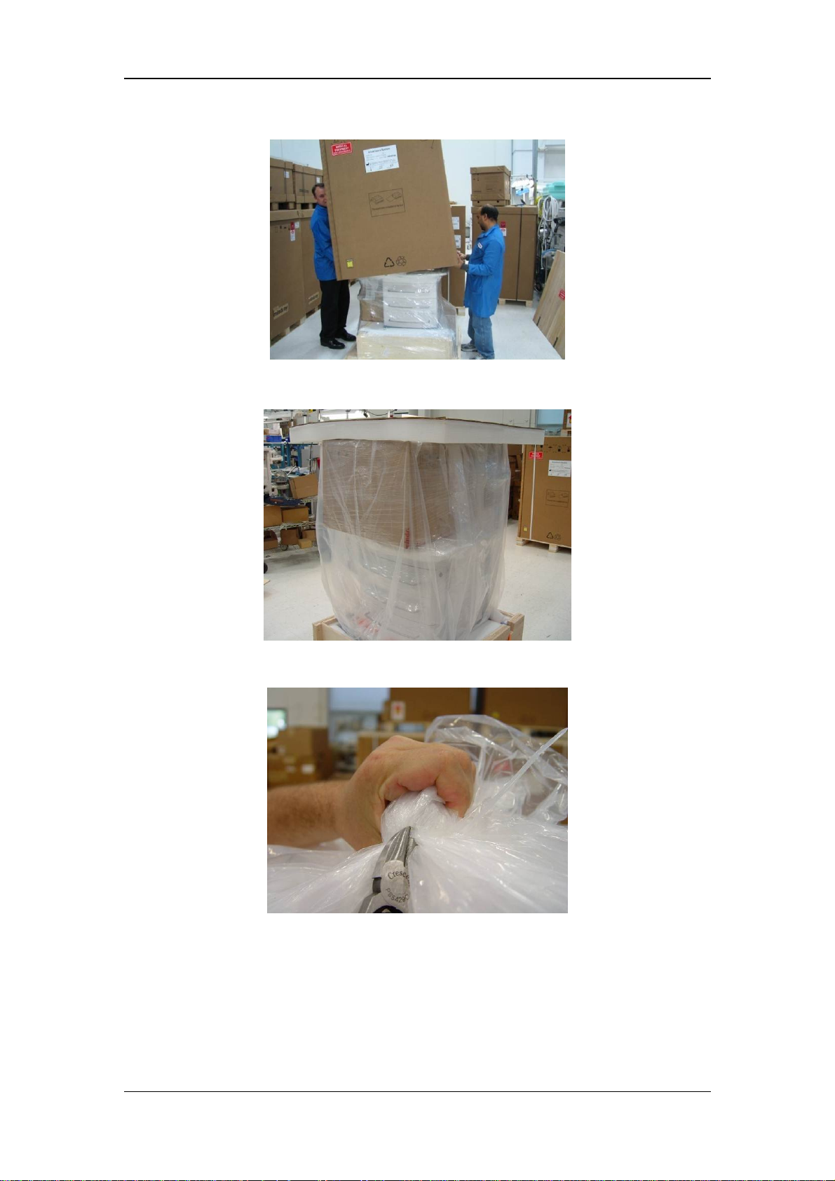
4. Lift the packing box and remove it from the top of the equipment.
5. Remove the foam from the top of this device.
6. Cut the plastic straps as shown below. Pull down the plastic bag from the equipment.
3-3
Page 82
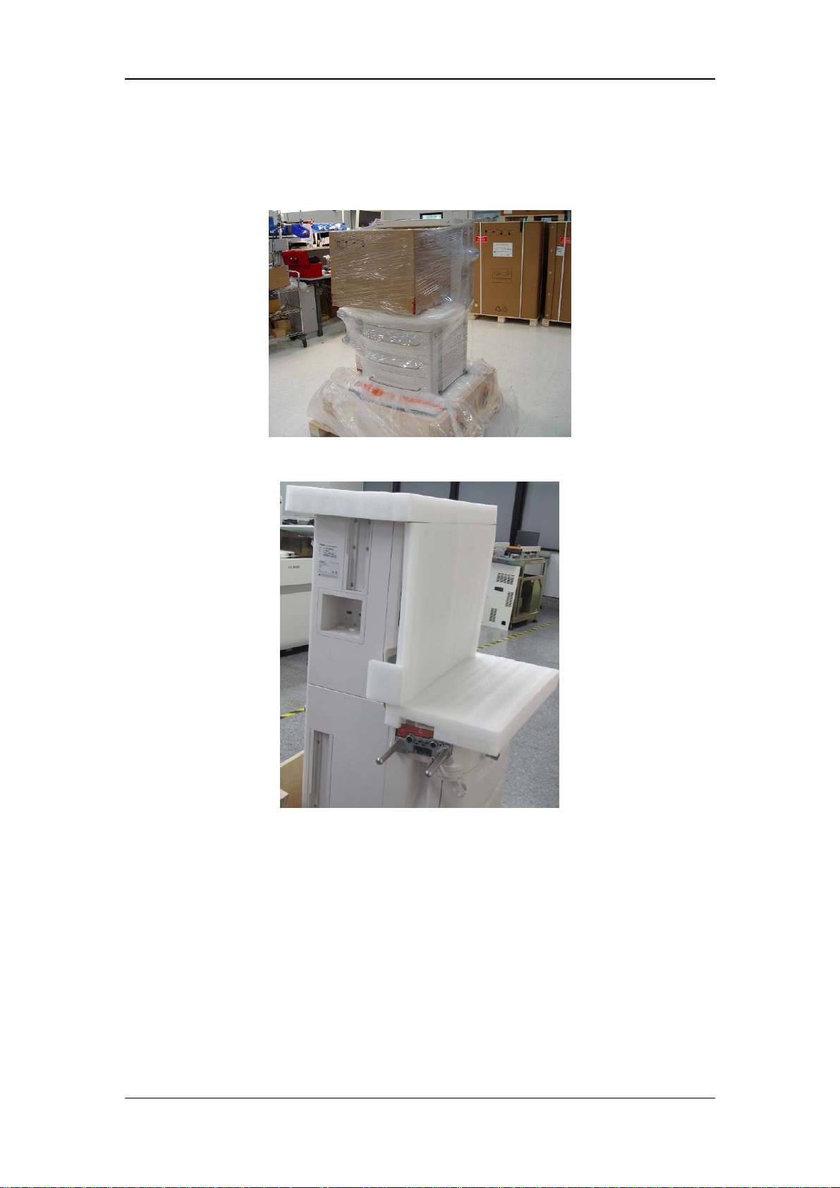
7. Cut the plastic straps close to the back of this device. Take care not to scratch or damage
the equipment. Remove and discard the plastic straps. Remove the empty box on the
equipment bench.
8. Remove the foam from the display and bench.
9. Use scissors to cut the two flexible packing straps attached to the base of the packing
box platform.
3-4
Page 83
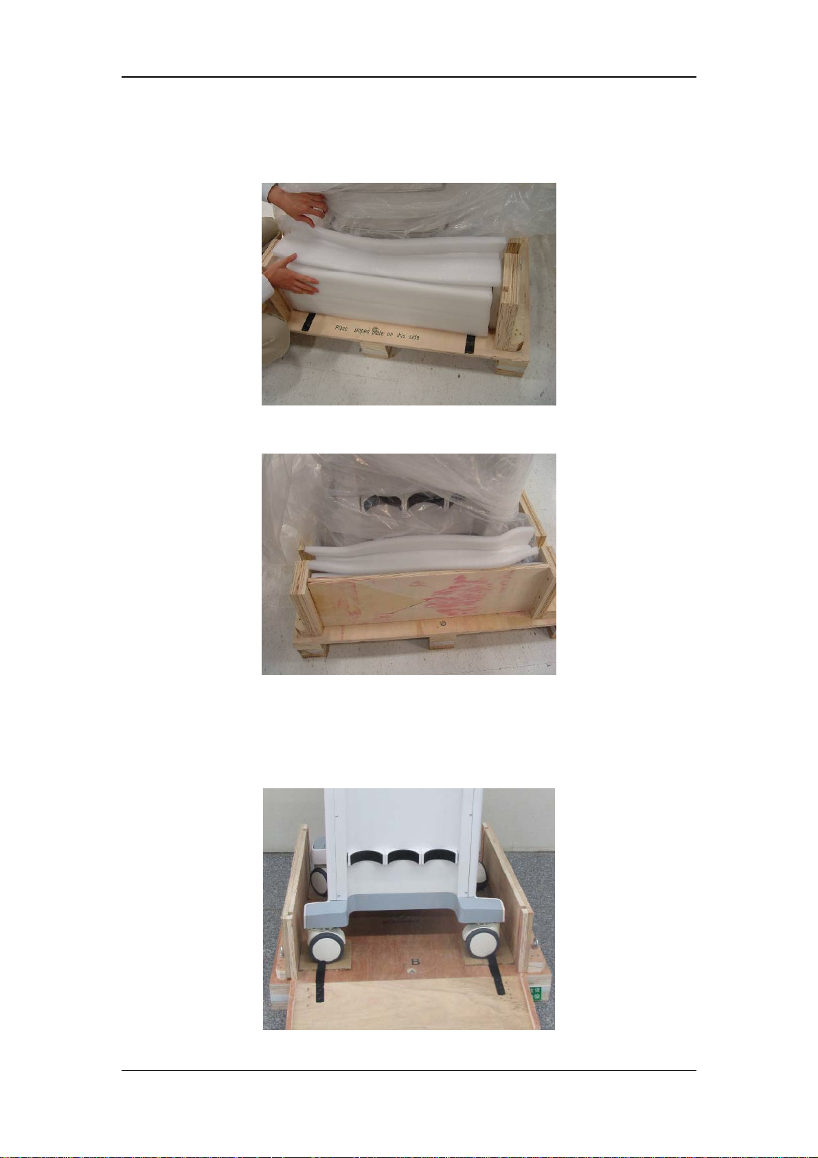
10. Remove the wood from the front of this device. Remove the foam and packing material
from around the front of the equipment.
11. Remove the foam and packing material from around the back the equipment.
12. Place the packing box cover beside the wooden box base, using as the slope for pushing
the equipment onto the floor, as shown below. Place the smooth side of the wood
upward. A supporting foot is available at the other side of the wood to support the slope.
Fix the slope onto the wooden box with buckle strap.
3-5
Page 84
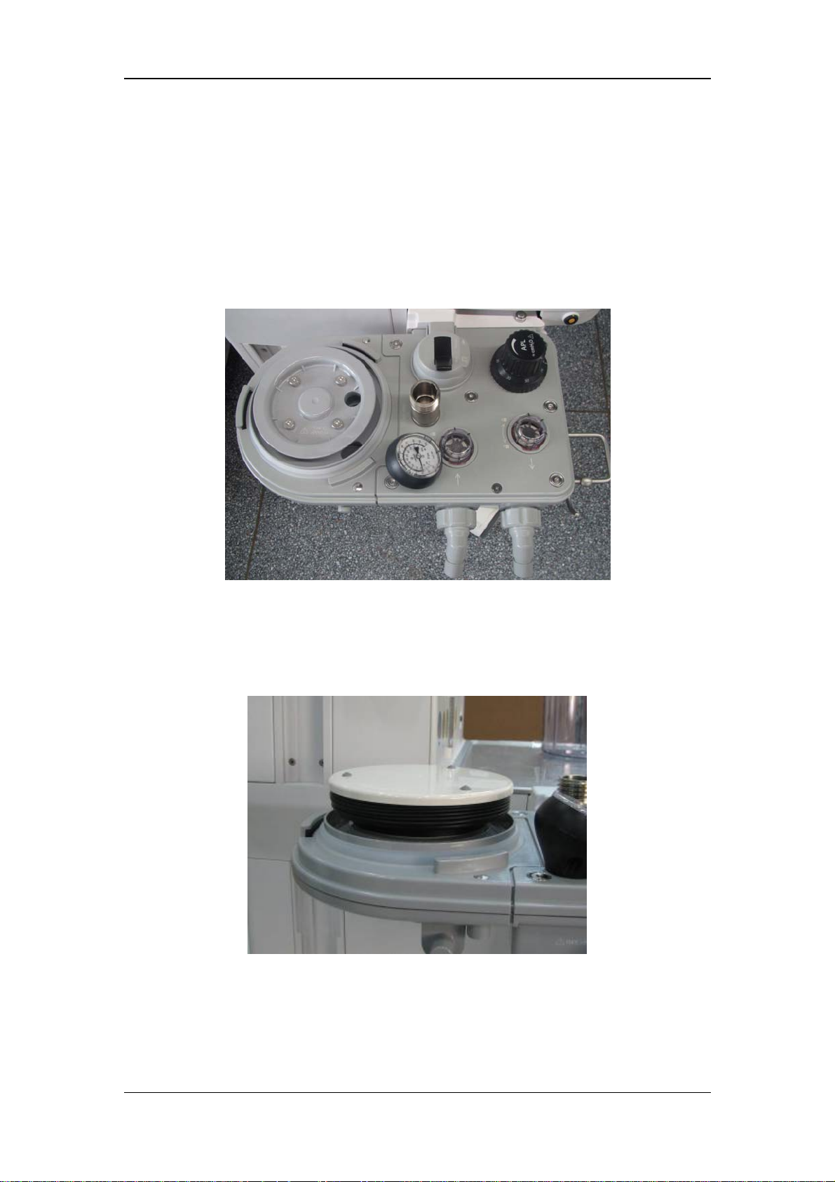
13. Rotate the casters for 90°. Then push this device gently to roll it down the slope.
Remove the packing box on the equipment. Keep the packing box in case that this
device needs re-packing.
14. Open the packing box and take out the patient circuit and bag arm assembly.
15. Install the patient circuit on one side of the device. Take care to align the assembly with
the circuit port and then push it to this device directly until it is stuck at the proper
position.
16. Open the small box containing bellows assembly and bellows housing gently. Remove
the plastic bag from the assembly and put the foam and plastic bag into the box.
17. Install the bellows onto the patient circuit. After installation, make sure that the bellows
are fully extended and surround the tabs of patient circuit.
3-6
Page 85
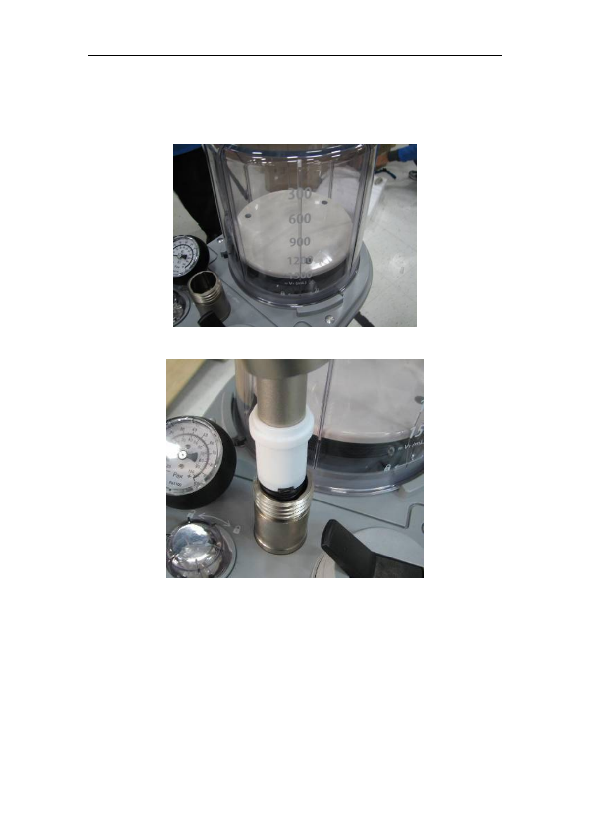
18. Place the bellows housing downward onto the patient circuit. Then rotate it clockwise to
fix it at proper position (the scale marks on the bellows housing shall be placed forward
for the convenience of being seen by the operator).
19. Align with the slots to install the bag arm assembly as shown below.
3-7
Page 86
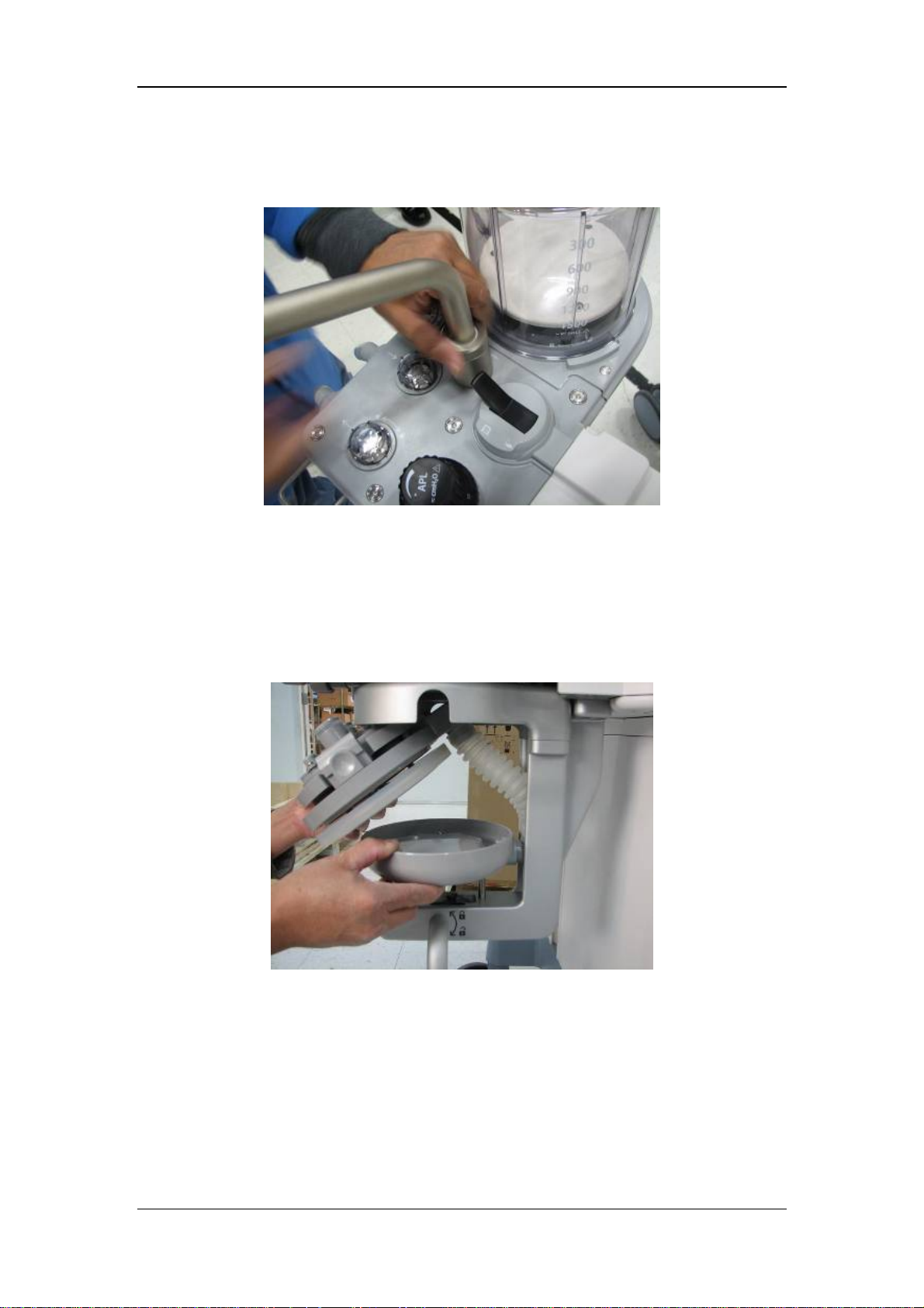
20. Push the bag arm assembly into the breathing system and tighten the fixing nut as shown
below.
21. Open the packing box and take out the detachable absorber canister assembly, waste gas
scavenging system hose, and waste gas scavenging assembly gently.
22. Install the white absorber canister hose onto the absorber canister assembly. Install the
absorber canister assembly when it is not stably placed. First install its lower part. Align
the pins with the holes. Then align the upper part. Push in the upper part upward until
the front and back latches are stuck at the proper position.
3-8
Page 87
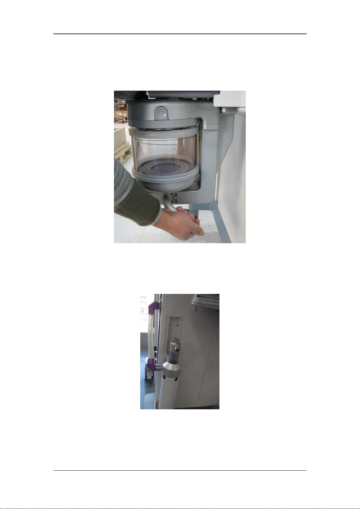
23. Fill Pre-pack or loose fill CO2 absorbent into the canister. Slide the canister into the
canister assembly. Rotate the lock bar anticlockwise for 90° to fix the canister at the
proper position.
24. Slide the scavenging assembly into the rail at the left bottom of this device (namely, the
same side with the breathing system assembly). Then tighten the thumbscrew to fix the
assembly at the proper position. Install one end of the scavenging hose onto the
scavenging assembly and the other end onto this device, as shown below.
3-9
Page 88

26. Open the top drawer and check if it contains the following:
Preoperative checklist
Inspiratory flow sensor and expiratory flow sensor (PN: 115-008264-00)
Drawer key (PN: 034-000353-00)
26. Before installing the cylinders onto the back of this device, make sure that washer
is already installed. Remove the tape fixing the washer. Then install the cylinders. Make
sure that the cylinders are fixed onto the respective cylinder connectors (marked with O2,
Air, and N2O).
27. Connect the gas supplies. Rotate the hose connectors clockwise to tighten them onto the
gas supply connectors. Make sure that the supply gas pressure is within the specified
range.
28. Connect the manual bag (supplied by the user) to the bag arm.
29. Connect the patient’s breathing circuit (supplied by the user) to the inspiratory and
expiratory connectors.
WARNING
Use breathing circuit and manual bag according to ASTMF1208. Standard male
22mm conical fittings can be used for breathing circuit and manual bag according
to ASTM F1054.
30. Rotate the knob at the top of AGSS tank until the float is between the minimum and
maximum marks. Connect the hose from the gas scavenger to the EVAC connector of
operating room.
31. Install the O2 sensor inside the stainless housing. Tighten the O2 sensor properly.
32. Connect the O2 sensor external cable between the O2 sensor and the side of this device.
Align the cable with the yellow mark on the connector.
33. Insert the power cord into the grounded socket. Set the main unit power switch (located
on the front of this device) to ON position to turn on this device. Wait until the LCD
display displays leak test related information. View if power-on selftest is successful.
Do not connect, disconnect, or move the breathing circuit or bag during selftest.
34. Install the patient monitor and arm according to the instructions in the monitoring kit.
WARNING
Use only Mindray approved patient monitor and arm for this device.
3-10
Page 89
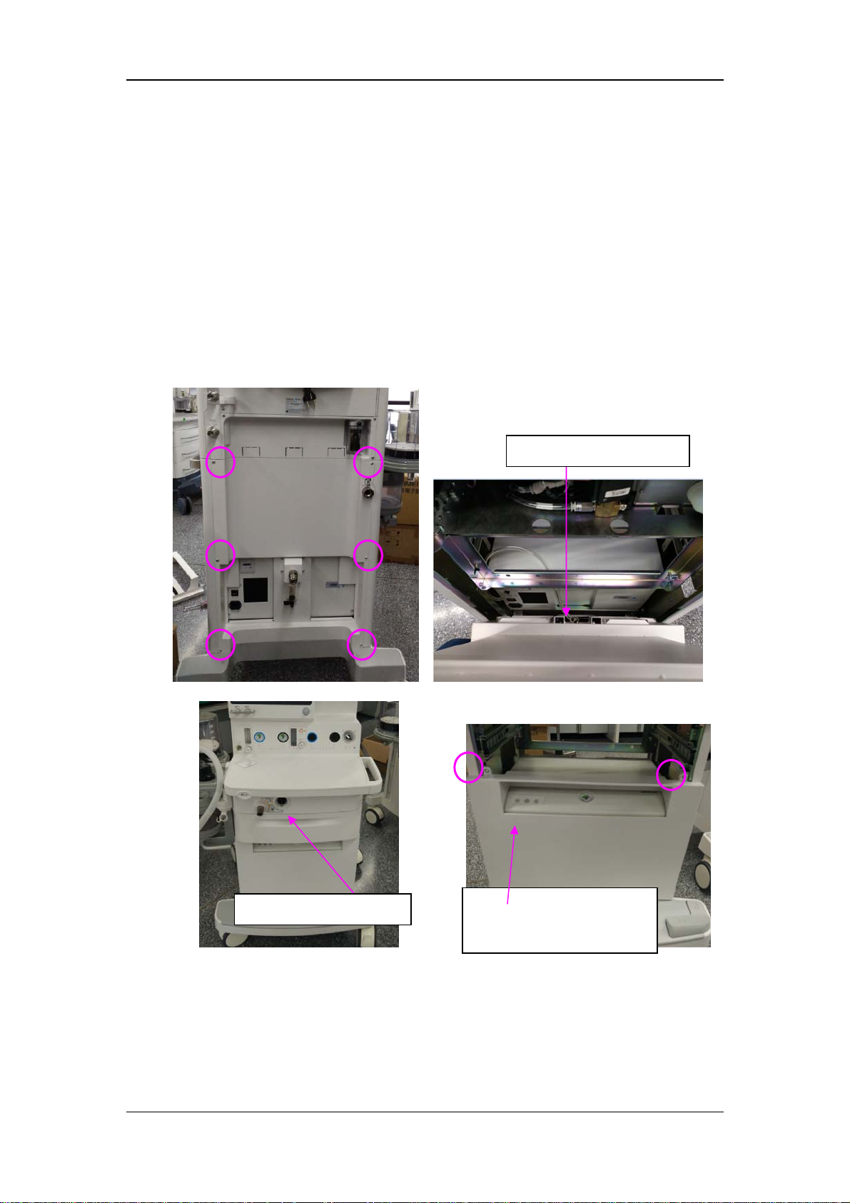
35. Put the following parts into the bottom drawer:
Operator’s manual
Sealing washer (P/N: 0348-00-0185)
36. Hang the user guide onto the handle of this device.
Take the following steps to install the anesthesia machine with an air compressor.
1. Loosen the six screws fixing the rear panel of the cart, remove the gas hose, and take out
the rear panel.
2. Remove a drawer from the front, loosen the two screws fixing the front panel of the air
compressor, and take out the front panel.
Take out the gas hose
Take out the drawer
Front panel of the air
compressor
3-11
Page 90
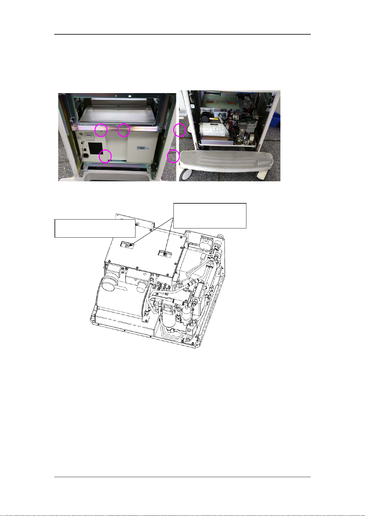
3. Loosen the five screws fixing the upper cover of the air compressor from behind, pull
out the upper cover assembly of the air compressor from the front, remove the cable
materials and pipelines connected to the upper cover, and take out the upper cover.
4. Use an inner hexagon screw driver to loosen the two transport protection screws fixing
the air pump.
Transport protection
screw
Inner hexagon screw driver
3-12
Page 91
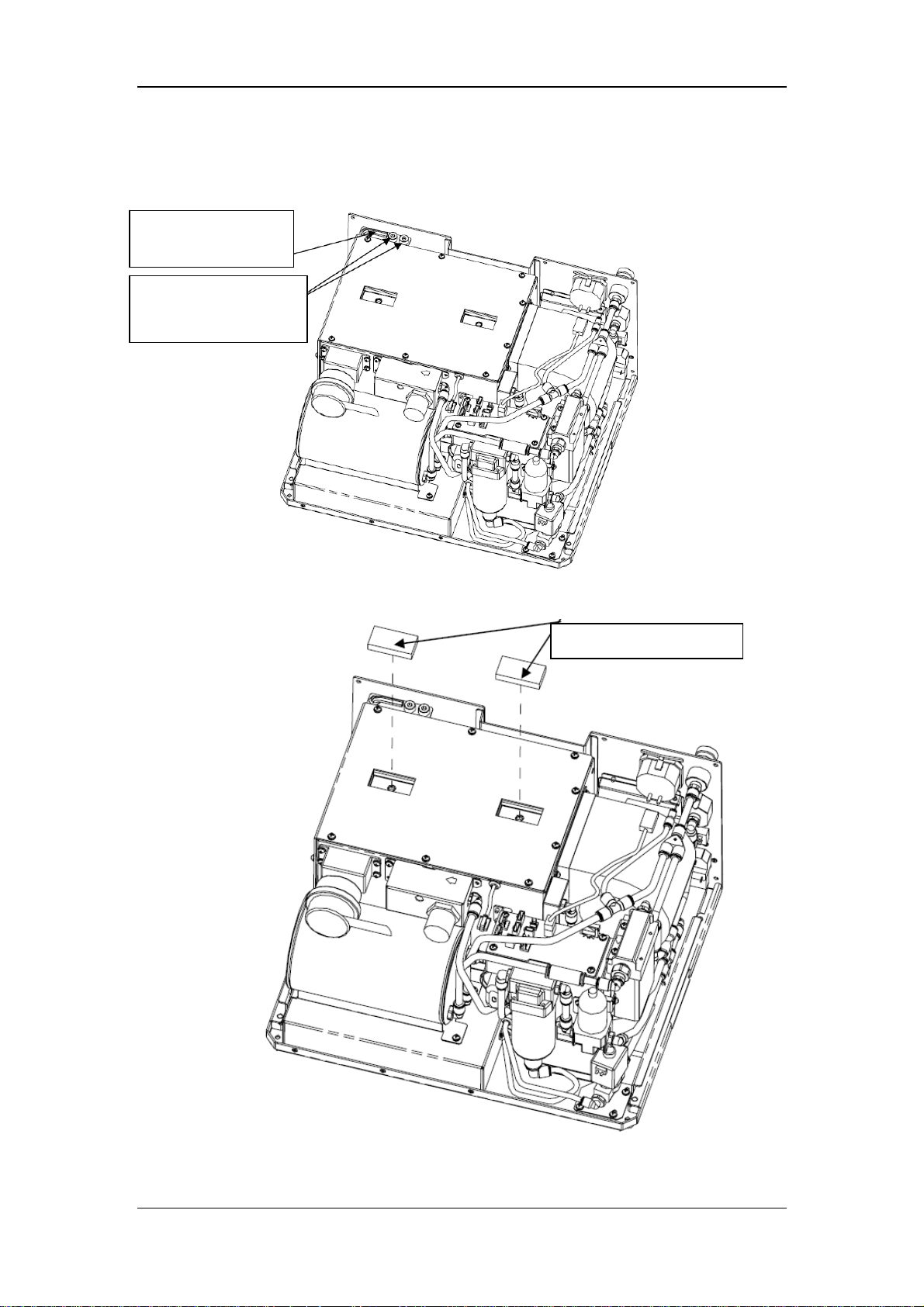
r
5. Fix the two transport protection screws on the positions as shown in the following
figure.
Inner hexagon screw
drive
Transport protection
screw
6. Install the two leakproof sponges where transport screws were.
Leakproof sponges
3-13
Page 92
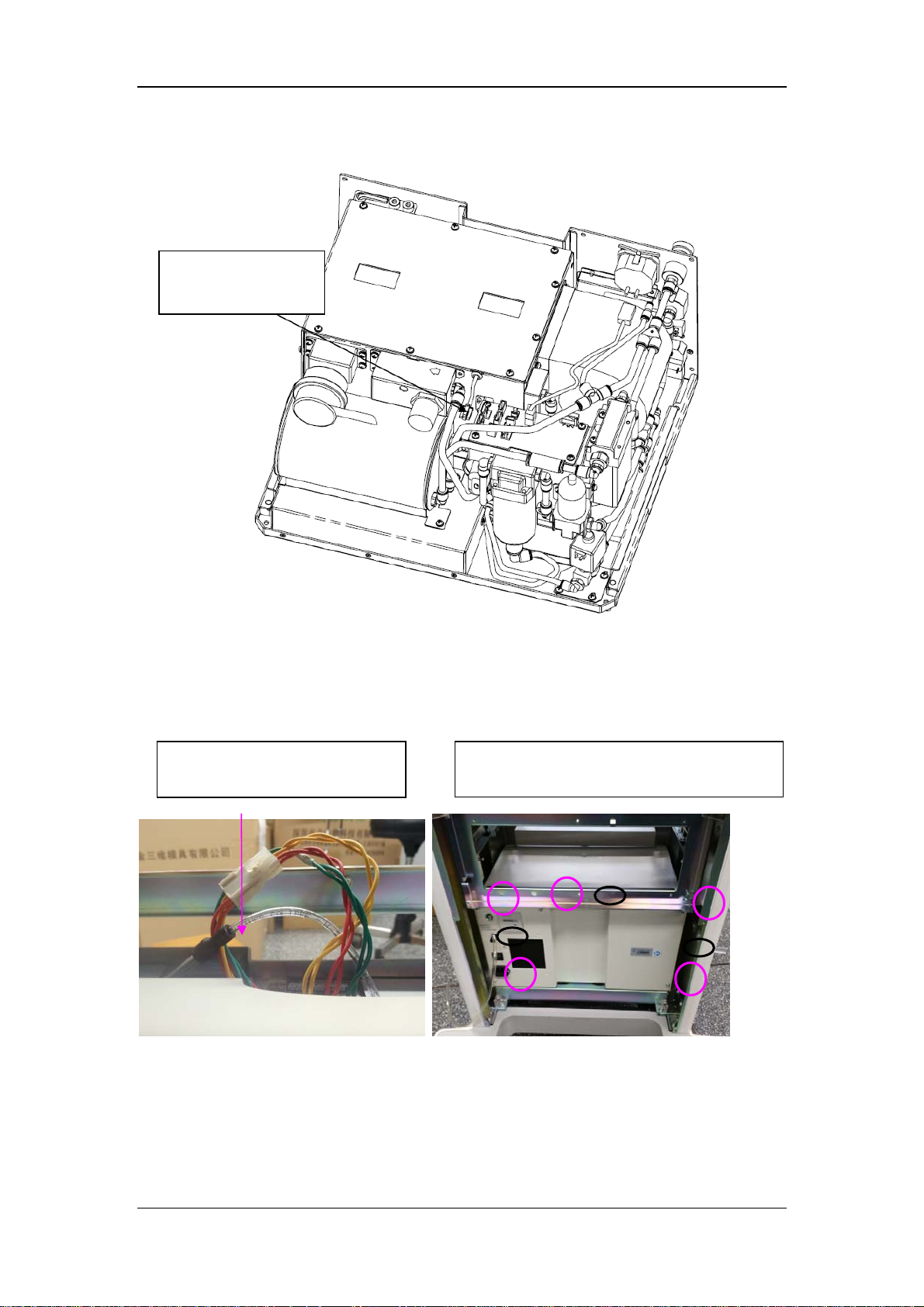
7. Insert the air pump into the power socket.
pip
p
Air pump power
socket
8. Close the upper cover by two thirds from the front of the air compressor along the guide
groove, connect the gas hose of the pressure gauge and indicator plug, push the upper
cover to the proper position, tighten the five screws in the rear, and stick the three safety
stickers to the positions circled in black, as shown in the following figure.
Connect the cable materials and
elines of the upper cover
Positions circled in black for safety stickers
and
ositions circled in red for screws
9. Use two screws to fix the front panel of the air compressor on the cart from the
front.
3-14
Page 93
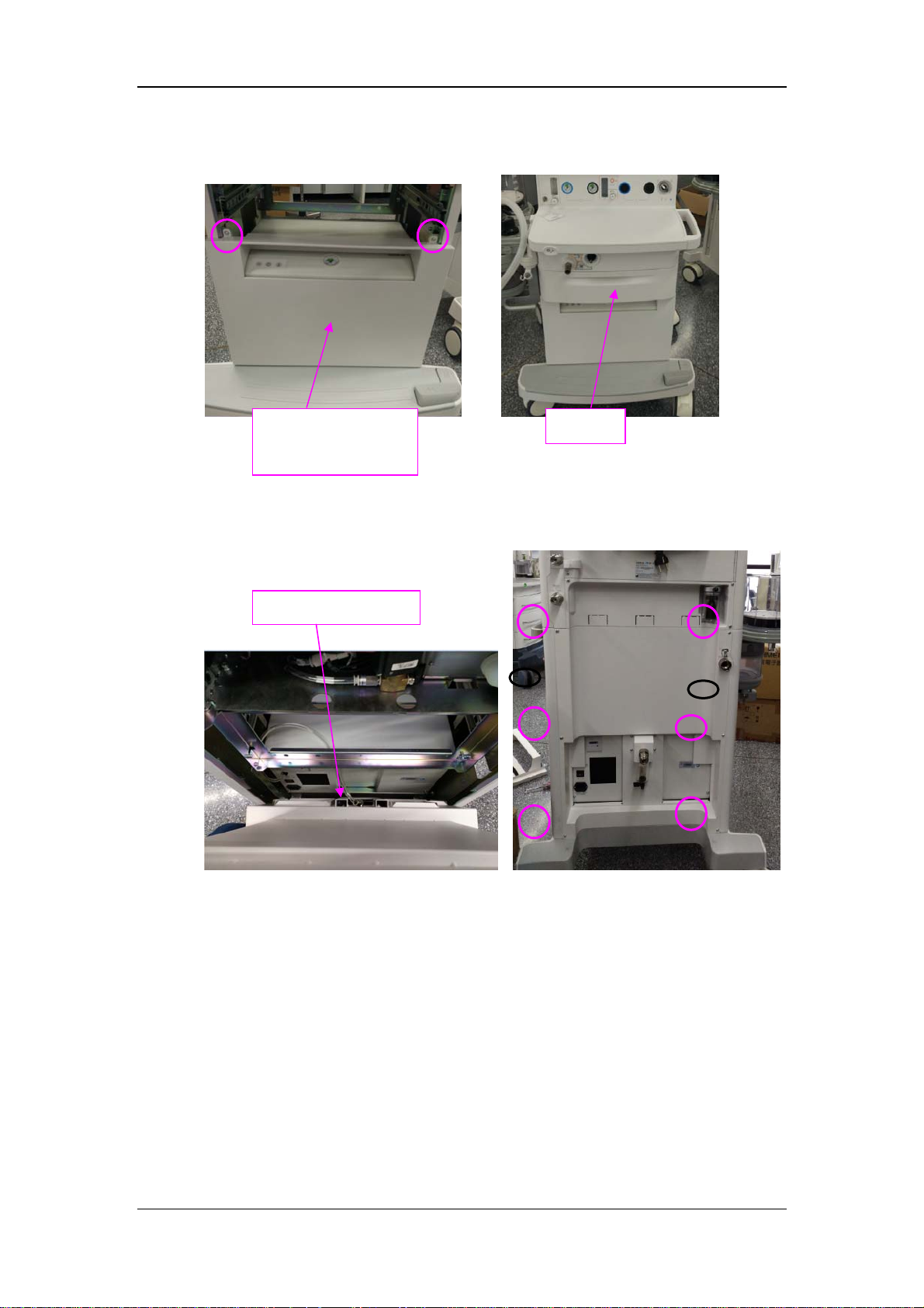
Install the drawer on the cart.
10.
Front panel of the air
compressor
1. Put the rear panel of the cart behind the cart, connect the gas hose, fix the rear panel
1
with six screws, and stick two safety stickers to the positions circled in black.
Connect the gas hose
Drawer
12. Take out the power cord, fixing plate of the power cord, and M3 screws, and fix the power
cord as shown in the following figure.
3-15
Page 94
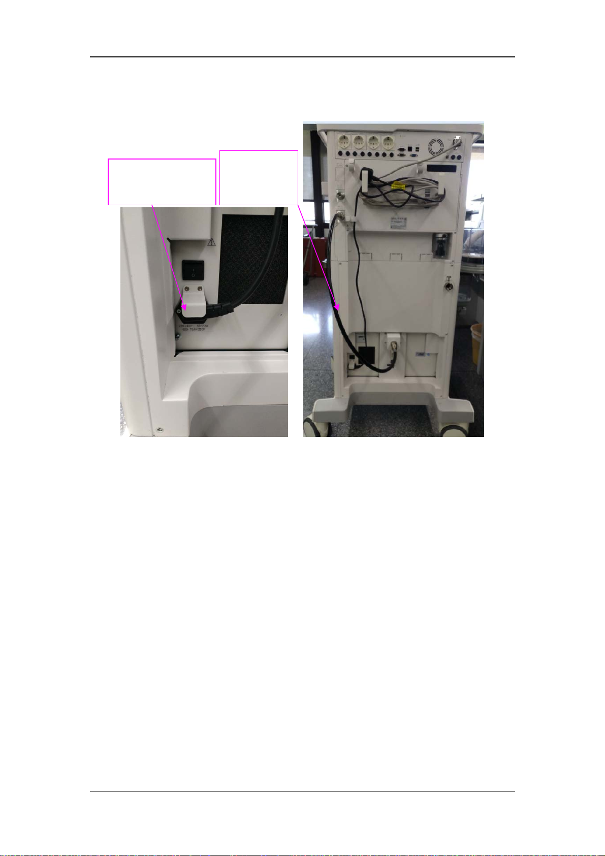
13. Connect the compressed air hose to the air outlet of the filter at one end and to the air source
inlet at the other end.
Fixing plate of the
power cord
Connect the
compressed
air hose
3-16
Page 95
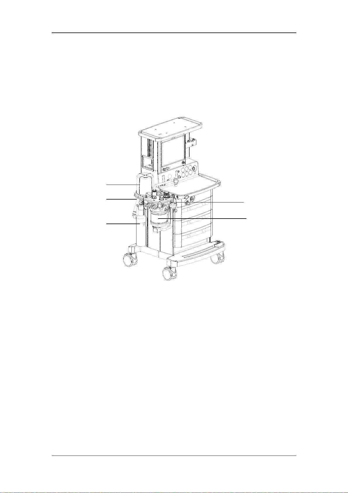
3.2.2 Breathing System, Breathing System Accessories and
Checkout Procedures
1
2
3
1. Breathing system 2. AGSS transfer tube
3. AGSS 4. CO2 absorbent
5. O2 sensor and cable
3.2.3 AGSS Connections
5
4
1. Take out the AGSS from the foam and plastic bag.
2. Install the AGSS onto this device via the GCX compatible rail system.
3. Connect the AGSS transfer tube between the AGSS inlet port and this device exhaust
port.
3-17
Page 96

3.2.3.1 Cylinder Wrench and User Guide
1. Fix the cylinder wrench onto the back of this device so that it can be used to open or
close cylinders without disconnecting from the machine.
2. Hang the user guide on the device handle.
3.2.4 Vaporizer
WARNING
If the vaporizer is incompatible with this device Anesthesia System, the vaporizer
will not work at all. Use vaporizers with Selectatec mounting system that are
compliant to ISO8835-4. Refer to the vaporizer manufacturer’s Instructions For
Use for filling or draining the vaporizer and other information.
For this device Anesthesia System, using or turning on more than one vaporizer
simultaneously is mechanically prevented by the Selectatec mount system. Do not
attempt to override this safety feature.
Use care in lifting and manipulating vaporizers during the mounting process as
their weight may be greater than expected, based on their size and shape.
NOTE
The barometric pressure at the customer side may be different from the factory
calibration pressure of anesthetic vaporizer. This may cause inaccurate
concentration output of anesthetic agent. The operator should continuously
monitor the concentration of anesthetic agent during system use.
3-18
Page 97
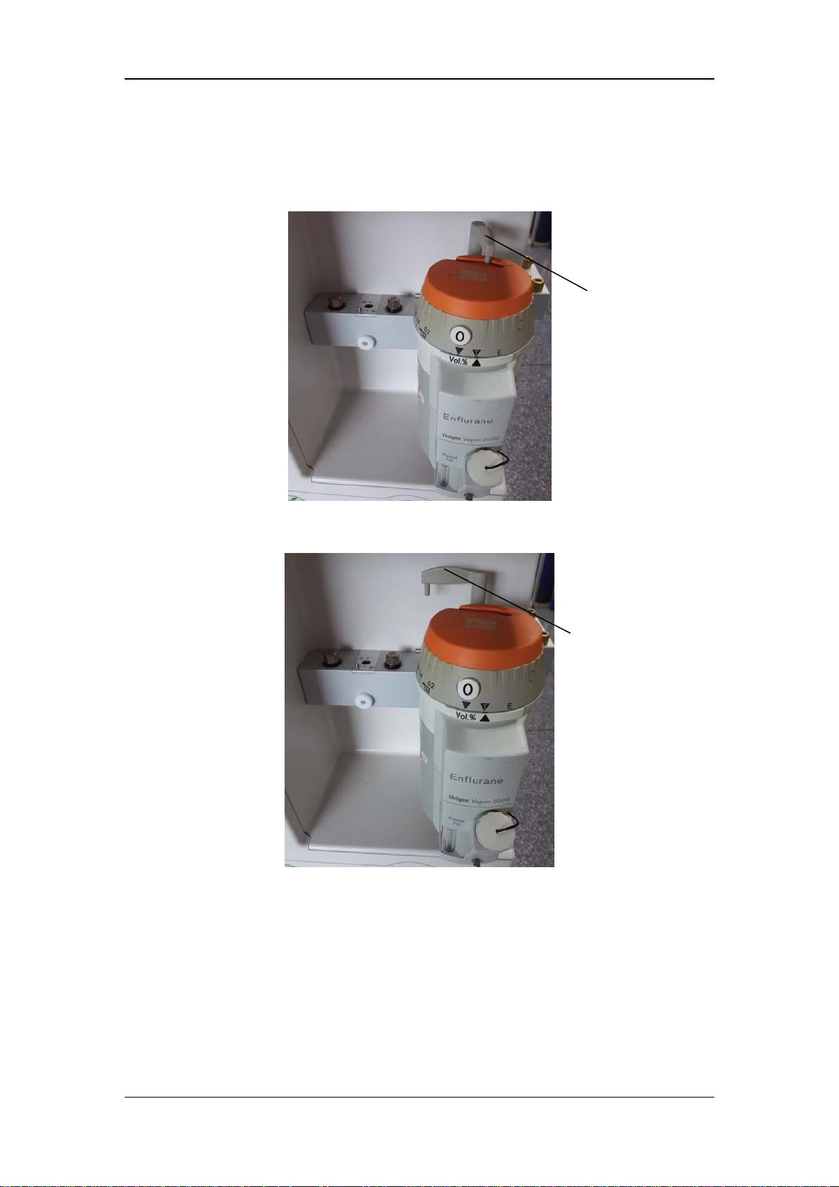
1. Align the vaporizer over the valve cartridges of the mounting bar. Hang the vaporizer on
the mounting bar as shown below. Note that the locking handle is in the unlocked
position.
Locking handle in
the unlocked
position
2. Rotate the locking handle clockwise to the locked position as shown below.
3.2.4.1 Assemble the Vaporizer
Locking handle in the
locked position
1. Mount the vaporizer onto the manifold.
2. Push and turn the locking lever clockwise to lock the vaporizer in position.
3. Ensure that the top of the vaporizer is horizontal. If not, remove the vaporizer and
reinstall it.
3-19
Page 98

4. When reinstalling the vaporizer, lift each vaporizer straight up off the manifold rather
than pulling forward. Do not rotate the vaporizer on the manifold.
5. If a vaporizer unintentionally lifts off the manifold, install it again and complete steps 1
through 3. If the vaporizer lifts off a second time, do not use the system.
NOTE
A Desflurane vaporizer may be mounted similarly as other vaporizers, but may
require a power cord. For more detailed instructions on installation and proper
use, refer to the specific manufacturer’s Instructions for Use of the Desflurane
vaporizer.
3.2.4.2 Fill the Vaporizer
NOTE
This device should use vaporizers with Selectatec mounting system that are
compliant to ISO8835-4. Refer to the vaporizer manufacturer’s Instructions For
Use for filling or draining the vaporizer and other information.
WARNING
Ensure that the correct anesthetic agent is used. The vaporizer is designed with the
specific anesthetic agent name on it and further indicated by color coded label. The
concentration of the anesthetic agent actually outputted will vary if the vaporizer is
filled with the wrong agent.
3.2.4.3 Drain the Vaporizer
WARNING
Do not reuse the agent drained from the vaporizer. Treat as a hazardous chemical
and follow local regulations for proper disposal.
3-20
Page 99

NOTE
This device should use vaporizers with Selectatec mounting system that are
compliant to ISO8835-4. Refer to the vaporizer manufacturer’s Instructions For
Use for filling or draining the vaporizer and other information.
3.2.5 Cylinder Installation
1. Remove the cover from a new O2, N2O, and AIR cylinder.
2. Mount one cylinder at a time onto the rear of the anesthesia machine.
3. Discard the cylinder's tank washer. Always use the approved tank washer provided with
this device.
4. Open the bail of each yoke and mount the cylinder over the tank washer.
5. Ensure the O2 cylinder mates to the O2 Pin Index Safety System (PISS) connection on
the O2 yoke. Close the yoke bail and use the hand-screw to tighten the cylinder to the
yoke port.
6. Ensure that the N2O cylinder mates to the N2O PISS connection on the N2O yoke.
Close the yoke bail and use the hand-screw to tighten the cylinder to the yoke port.
7. Ensure that the AIR cylinder mates to the AIR PISS connection on the AIR yoke. Close
the yoke bail and use the hand-screw to tighten the cylinder to the yoke port.
3.2.6 Patient Circuit and CO2 Absorbent
1. Attach a patient circuit to the inspiratory and expiratory ports as detailed in the
directions for use. Attach the breathing bag and any other respiratory accessories as
described.
2. Put the CO
3. Install the absorber canister with a quarter turn of the lever at the bottom the absorber
assembly, ensuring tight seal.
absorbent in the absorber canister.
2
3-21
Page 100

3.2.7 Monitoring Products Mounting and Electrical Connection
(optional)
1. Mount the monitor (if available) according to the manufacturer’s monitor assembly
instructions.
NOTE
Use of other monitor and mounting hardware is performed by the installer.
2. After mounting a monitor to this device, connect it to one of the AC outlets located on
the rear of this device.
3. Turn on each monitor one at a time. Verify that the circuit breaker holds without
tripping.
4. Dress each line cord neatly along the side of the anesthesia machine or tucked inside the
monitor arm. An optional cable routing kit is available. The cable routing kit contains
three (3) clips, screws, and two (2) Ethernet cables. The clips attach to three (3) sets of
holes on the rear door of this device. Ethernet and power cables can be routed through
the clips.
3.2.8 Anesthesia Module Installation and Waste Gas
Scavenging
1. The respiratory gas monitoring product has an exhaust hole for emitting waste gas. The
exhaust hole on the gas monitor must be connected to the sample gas return port at the
back of this device.
2. Make sure that a tight connecting fitting is attached to the exhaust port of gas monitor.
Make sure that the other end of the same tube is connected to the back of this device.
3. Dress the exhaust tube neatly along the side of the anesthesia machine or tuck it inside
the monitor arm so that it cannot be easily pulled and it does not extend far from the
main chassis.
3.2.9 Negative Pressure Suction
For the installation of negative pressure suction, see 12.8 Negative Pressure Suction Device of
WATO EX-55/65 Operator’s Manual.
3-22
 Loading...