

Page 1
DE-Betriebsanweisung
W 4446 Demomodell
D
M.-Nr. 06 887 840
Page 2

Inhalt
Sicherheits- und Warnhinweise . . . . . . . . . . . . . . . . . . . . . . . . . . . . . . . . . . . . . . 3
Entsorgung der Transportverpackung. . . . . . . . . . . . . . . . . . . . . . . . . . . . . . . . . . . 4
Betrieb. . . . . . . . . . . . . . . . . . . . . . . . . . . . . . . . . . . . . . . . . . . . . . . . . . . . . . . . . . . 5
Displaysprache einstellen . . . . . . . . . . . . . . . . . . . . . . . . . . . . . . . . . . . . . . . . . . . . 5
Demo-Modus einschalten . . . . . . . . . . . . . . . . . . . . . . . . . . . . . . . . . . . . . . . . . . . . 5
Demo-Modus betreiben. . . . . . . . . . . . . . . . . . . . . . . . . . . . . . . . . . . . . . . . . . . . . . 5
Trommel bewegen . . . . . . . . . . . . . . . . . . . . . . . . . . . . . . . . . . . . . . . . . . . . . . . 5
Demo-Modus unterbrechen . . . . . . . . . . . . . . . . . . . . . . . . . . . . . . . . . . . . . . . . 5
Kundendienst . . . . . . . . . . . . . . . . . . . . . . . . . . . . . . . . . . . . . . . . . . . . . . . . . . . . . 6
Reparaturen . . . . . . . . . . . . . . . . . . . . . . . . . . . . . . . . . . . . . . . . . . . . . . . . . . . . 6
Aufstellen und Anschließen . . . . . . . . . . . . . . . . . . . . . . . . . . . . . . . . . . . . . . . . . 7
Aufstellfläche . . . . . . . . . . . . . . . . . . . . . . . . . . . . . . . . . . . . . . . . . . . . . . . . . . . . . . 7
Waschautomaten aufstellen. . . . . . . . . . . . . . . . . . . . . . . . . . . . . . . . . . . . . . . . . . . 7
Transportsicherung entfernen . . . . . . . . . . . . . . . . . . . . . . . . . . . . . . . . . . . . . . . . . 7
Transportsicherung einbauen . . . . . . . . . . . . . . . . . . . . . . . . . . . . . . . . . . . . . . . . . 9
Ausrichten . . . . . . . . . . . . . . . . . . . . . . . . . . . . . . . . . . . . . . . . . . . . . . . . . . . . . . . 10
Elektroanschluss . . . . . . . . . . . . . . . . . . . . . . . . . . . . . . . . . . . . . . . . . . . . . . . . . . 11
Technische Daten. . . . . . . . . . . . . . . . . . . . . . . . . . . . . . . . . . . . . . . . . . . . . . . . . 12
2
Page 3
Sicherheits- und Warnhinweise
Lesen Sie vor dem ersten Be
,
trieb des Waschautomaten die Be
triebsanweisung. Sie gibt wichtige
Hinweise für die Sicherheit, den Ge
brauch und die Wartung des Wasch
automaten. Dadurch schützen Sie
sich und verhindern Schäden am
Waschautomaten.
Bewahren Sie diese Betriebsanwei
sung auf.
-
-
-
-
Bestimmungsgemäße Verwen
dung
Der Waschautomat ist ausschließ-
lich für Demonstrationszwecke
konstruiert und nicht in vollem Umfang
funktionsfähig.
Die Ausführung des Demo-Modus mit
befüllter Trommel ist nicht erlaubt.
Alle andere Verwendungszwecke als
das Starten des Demo-Modus sind verboten und gefährlich. Der Hersteller
haftet nicht für Schäden, die durch bestimmungswidrigen Gebrauch oder fal
sche Bedienung verursacht werden.
Technische Sicherheit
Kontrollieren Sie den Waschauto
maten vor der Aufstellung auf äu
ßere sichtbare Schäden.
Bei Beschädigungen den Waschauto
maten nicht in Betrieb nehmen.
-
-
-
Vor dem Anschließen des Wasch
automaten unbedingt die An
schlussdaten (Absicherung, Spannung
und Frequenz) auf dem Typenschild mit
denen des Elektronetzes vergleichen.
-
Erfragen Sie diese im Zweifelsfalle bei
einer Elektro-Fachkraft.
Der Anschluss darf nur an eine nach
VDE 0100 ausgeführte fest installierte
Elektroanlage erfolgen.
Zur Erhöhung der Sicherheit empfiehlt
der VDE in seiner Leitlinie
-
DIN VDE 0100 Teil 739, dem Gerät
einen FI-Schutzschalter mit einem Aus
lösestrom von 30 mA (DIN VDE 0664)
vorzuschalten.
Die elektrische Sicherheit dieses
Waschautomaten ist nur dann gewährleistet, wenn er an ein vorschriftsmäßig installiertes Schutzleitersystem
angeschlossen wird. Es ist sehr wichtig,
dass diese grundlegende Sicherheitsvoraussetzung geprüft und im Zweifelsfall die Hausinstallation durch eine
Fachkraft überprüft wird. Der Hersteller
kann nicht für Schäden verantwortlich
gemacht werden, die durch einen feh
lenden oder unterbrochenen Schutzlei
ter verursacht werden.
Defekte Bauteile dürfen nur gegen
Miele Original Ersatzteile ausge
tauscht werden. Nur bei diesen Teilen
können wir gewährleisten, dass sie in
vollem Umfang die Sicherheitsanforde
rungen erfüllen, die wir an unsere Ge
räte stellen.
-
-
-
-
-
-
-
-
3
Page 4

Sicherheits- und Warnhinweise
Wenn die Netzanschlussleitung be
schädigt ist, muss diese durch von
Miele autorisierte Fachkräfte ersetzt
werden, um Gefahren für den Benutzer
zu vermeiden.
Im Fehlerfall oder bei der Reini
gung und Pflege ist der Waschau
tomat nur dann vom Elektronetz ge
trennt, wenn:
der Netzstecker des Waschautoma
–
ten gezogen ist oder
die Sicherung der Hausinstallation
–
ausgeschaltet ist oder
– die Schraubsicherung der Hausin-
stallation ganz herausgeschraubt ist.
Den Waschautomaten nicht am
Wasserzulauf sowie am Wasserablauf anschießen.
-
-
Gebrauch
Stellen Sie den Waschautomaen
nicht in frostgefährdeten Räumen
auf. Bereits Temperaturen um dem Ge
frierpunkt beeinträchtigen die Funk
tionsfähigkeit des Waschautomaten.
-
Entsorgung der Transportver
-
packung
Die Verpackung schützt den Waschau
tomaten vor Transportschäden. Die Ver
packungsmaterialien sind nach umwelt
verträglichen und entsorgungstechni
-
schen Gesichtspunkten ausgewählt
und deshalb recycelbar.
Das Rückführen der Verpackung in den
-
Materialkreislauf spart Rohstoffe und
verringert das Abfallaufkommen. Ihr
Fachhändler nimmt die Verpackung zu
rück.
-
-
-
-
-
-
-
Beaufsichtigen Sie Kinder, die sich
in der Nähe des Waschautomaten
aufhalten. Lassen Sie Kinder nie mit
dem Waschautomaten spielen.
4
Page 5

Betrieb
Der Waschautomat ist anschlussfer
tig und startbereit, sobald es ord
-
-
nungsgemäß aufgestellt ist.
Displaysprache einstellen
Schalten Sie den Waschautomaten
^
über die Taste
Drücken Sie die beiden Menü-Tasten
^
I-Ein/0-Aus
ein.
gleichzeitig bis im Display erscheint:
Einstellungen
Sprache F
weiter
^ Bestätigen Sie
rechten
Sprache
deutsch
Menü
) OK
Sprache
-Taste OK.
OK
J mit der
^ Wählen Sie die gewünschte Sprache
durch Drücken der linken
Menü
-Taste
~ .
^
Bestätigen Sie die Sprache mit der
Menü
rechten
-Taste OK.
Demo-Modus einschalten
Voraussetzung:
B Taste
Start/Stop
kurz loslassen und
sofort ...
C ... für weitere ca. 3 Sekunden drü
-
cken.
D Taste
Start/Stop
loslassen.
E Zum Starten des Demo-Modus den
Hinweis im Display beachten.
Demo-Modus betreiben
Das Demo-Programm läuft automatisch
in einer Endlosschleife ab.
Trommel bewegen
^ Drücken Sie die Taste
Start/Stop
wenn sich die Trommel drehen soll.
Die Trommel dreht sich für wenige
Minuten und kann anschließend
durch erneutes Drücken der Taste
Start/Stop
wieder aktiviert werden.
Demo-Modus unterbrechen
^ Schalten Sie den Waschautomaten
mit der Taste
I-Ein/0-Aus
aus.
Demo-Modus fortsetzen:
^
Schalten Sie den Waschautomaten
mit der Taste
I-Ein/0-Aus
ein.
Das Demo-Programm beginnt wieder
automatisch von vorn.
,
–
Das Gerät ist ausgeschaltet.
–
Die Tür ist geschlossen.
A Taste
Start/Stop
das Gerät mit der Taste
drücken und dabei
I-Ein/0-Aus
einschalten. Die blinkende Taste
Start/Stop
solange gedrückt halten,
bis die Kontrollleuchte der Taste
Start/Stop
statisch leuchtet.
Demo-Modus beenden
Siehe Vorgang "Demo-Modus einschal
ten".
-
5
Page 6
Kundendienst
Reparaturen
Bei Störungen, die Sie nicht selbst be
heben können, benachrichtigen Sie bit
te:
Ihren Miele Fachhändler oder
–
den Miele Werkkundendienst.
–
Die Telefonnummer des Werkkun
dendienstes finden Sie auf der
Rückseite dieser Gebrauchsanwei
sung.
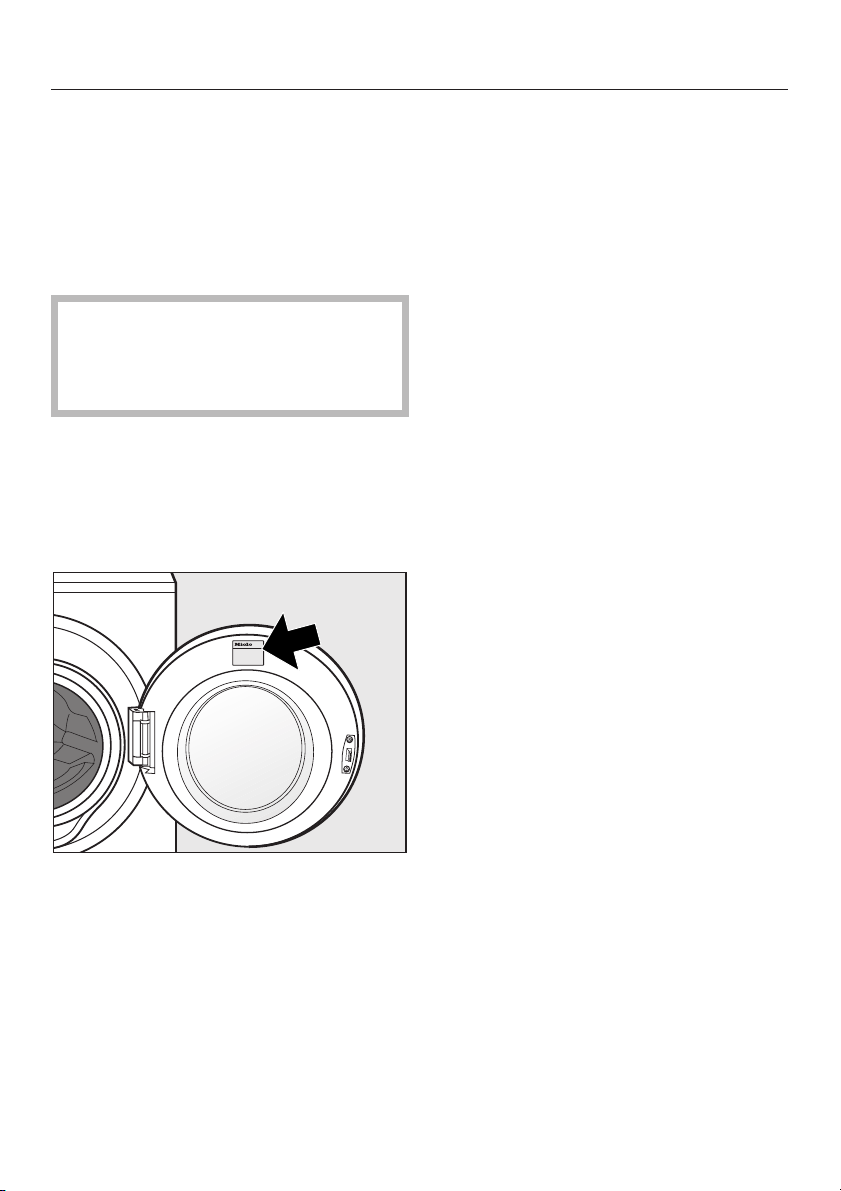
Der Kundendienst benötigt Modell und
Nummer Ihres Waschautomaten. Beide
Angaben finden Sie auf dem Typenschild bei geöffneter Fülltür oberhalb
des Schauglases.
-
-
-
-
6
Page 7
Aufstellen und Anschließen
Aufstellfläche
Als Aufstellfläche eignet sich am besten
eine Betondecke. Diese gerät im Ge
gensatz zu einer Holzbalkendecke oder
einer Decke mit "weichen" Eigenschaf
ten beim Schleudern selten in Schwin
gung.
Beachten Sie:
Stellen Sie den Waschautomaten lot
^
recht und standsicher auf.
Stellen Sie den Waschautomaten
^
nicht auf weichen Fußbodenbelägen
auf, da der Waschautomat sonst
während des Schleuderns vibriert.
Bei Aufstellung auf einer Holzbalkendecke:
^ Stellen Sie den Waschautomaten auf
eine Sperrholzplatte (mindestens
59x52x3 cm). Die Platte sollte mit
möglichst vielen Balken, jedoch nicht
nur mit den Fußbodenbrettern verschraubt werden.
-
-
-
-
Waschautomaten aufstellen
Nutzen Sie für den Transport des
Waschautomaten vom Verpackungsbo
den zum Aufstellungsort die vorderen
Griffmulden und den hinteren Deckel
überstand.
Beachten Sie:
Fassen Sie zum Heben nicht an die
^
Fülltür.
Gerätefüße und Aufstellfläche
,
müssen trocken sein, sonst besteht
Rutschgefahr beim Schleudern.
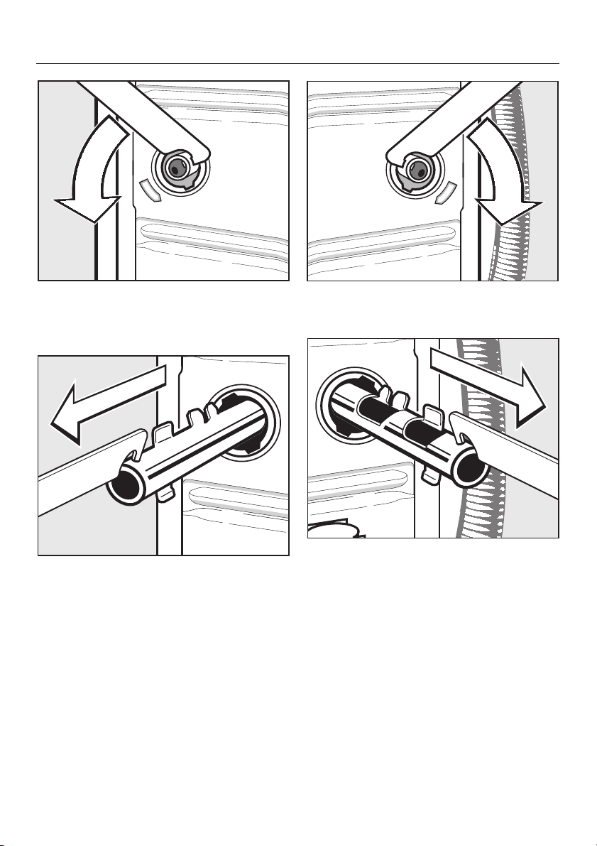
Transportsicherung entfernen
-
-
Aufstellung möglichst in einer Ecke des
Raumes. Dort ist die Stabilität jeder De
cke am größten.
,
Bei Aufstellung auf einen bausei
tig vorhandenen Sockel (Betonso
ckel oder gemauerter Sockel) muss
der Waschautomat durch Spannla
schen (erhältlich beim Miele Fach
handel oder Miele Kundendienst)
gesichert werden. Sonst besteht die
Gefahr, dass der Waschautomat
beim Schleudern vom Sockel fällt.
-
-
-
-
-
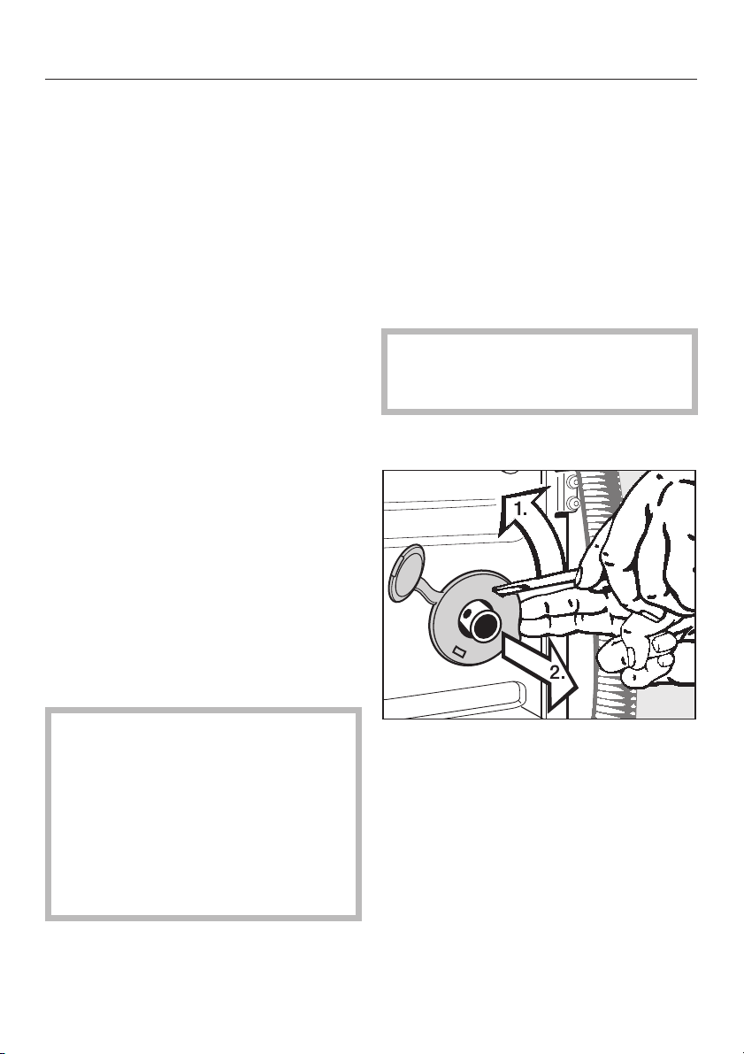
^
Entfernen Sie die linke und die rechte
Drehsicherung.
1. Drehsicherung mit einem Schrauben
dreher aushaken.
2. Drehsicherung abnehmen.
-
7
Page 8
Aufstellen und Anschließen
Drehen Sie die linke Transportstange
^
mit dem beigelegten Maulschlüssel
um 90°, und
^
ziehen Sie die Transportstange
heraus.
Drehen Sie die rechte Transportstan
^
ge um 90°, und
^
ziehen Sie die Transportstange
heraus.
-
8
Page 9
Aufstellen und Anschließen
Der Waschautomat darf ohne
,
Transportsicherung nicht transpor
tiert werden.
Bewahren Sie die Transportsiche
rung auf. Sie muss vor einem Trans
port des Waschautomaten (z.B. bei
einem Umzug) wieder montiert wer
den.
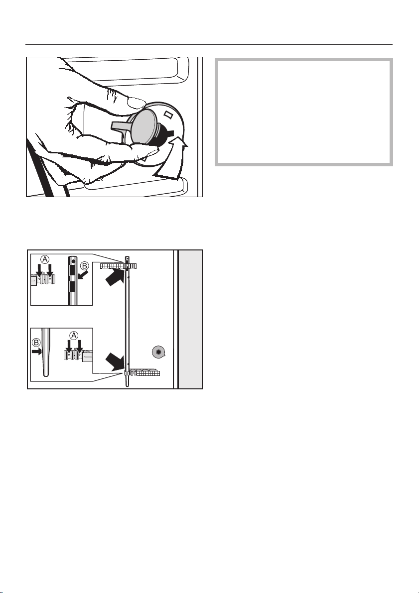
Transportsicherung einbauen
-
-
-
-
Verschließen Sie die Löcher mit den
^
Drehsicherungen und den daran be
festigten Stopfen.
^
Befestigen Sie die Transportstangen
an der Rückwand des Waschautoma
ten. Achten Sie darauf, dass die Boh
rungen b auf die Zapfen a gesteckt
werden.
Der Einbau der Transportsicherung er
folgt in umgekehrter Reihenfolge.
-
-
-
-
9
Page 10

Aufstellen und Anschließen
Ausrichten
Der Waschautomat muss lotrecht und
gleichmäßig auf allen vier Füßen ste
hen, damit ein einwandfreier Betrieb
gewährleistet ist.
-
Drehen Sie die Kontermutter 2 mit
^
dem beigelegten Maulschlüssel im
Uhrzeigersinn los. Schrauben Sie die
Kontermutter 2 zusammen mit dem
Fuß 1 heraus.
Eine unsachgemäße Aufstellung erhöht
den Wasser- und Energieverbrauch
und der Waschautomat kann wandern.
Fuß herausdrehen und kontern
Der Ausgleich des Waschautomaten erfolgt über die vier Schraubfüße. Im Aus
lieferungszustand sind alle Füße hinein
gedreht.
^ Prüfen Sie mit einer Wasserwaage,
ob der Waschautomat lotrecht steht.
^ Halten Sie den Fuß 1 mit einer Was-
serpumpenzange fest. Drehen Sie
die Kontermutter 2 wieder mit dem
Maulschlüssel gegen das Gehäuse
fest.
-
-
,
Alle vier Kontermuttern müssen
fest gegen das Gehäuse gedreht
sein. Bitte überprüfen Sie auch die
Füße, die beim Ausrichten nicht he
rausgedreht wurden. Sonst besteht
die Gefahr, dass der Waschautomat
wandert.
Der Waschautomat darf nicht unter
gebaut werden.
-
-
10
Page 11

Elektroanschluss
Aufstellen und Anschließen
Der Waschautomat ist mit Wechsel
strom-Anschlusskabel und Schuko-Ste
cker anschlussfertig für Wechselstrom
~230 V 50 Hz ausgerüstet.
Die Zugänglichkeit des Schuko-Ste
ckers muss immer gewährleistet sein,
um den Waschautomaten von der Netz
versorgung zu trennen.
Der Anschluss darf nur an eine nach
VDE 0100 ausgeführte Elektroanlage
erfolgen.
In keinem Fall sollte der Waschautomat
an Verlängerungskabeln, wie z.B. Mehrfach-Tischsteckdosen o. ä., angeschlossen werden, um eine potentielle
Gefahrenquelle (Brandgefahr) auszuschließen.
Zur Erhöhung der Sicherheit empfiehlt
der VDE in seiner Leitlinie DIN VDE
0100 Teil 739, dem Waschautomaten einen FI-Schutzschalter mit einem Auslösestrom von 30 mA (DIN VDE 0664)
vorzuschalten.
-
-
-
-
Wird ein FI-Schutzschalter verwendet,
ist nur der Typ A gemäß
DIN VDE 0664 t, pulsstromsensitiver
Fehlerstromschutzschalter, zu verwen
den.
Über die Nennaufnahme und die ent
sprechende Absicherung gibt das Ty
penschild Auskunft. Vergleichen Sie die
Angaben auf dem Typenschild mit den
Daten des Elektronetzes.
-
-
-
11
Page 12

Technische Daten
Höhe 850 mm
Breite 595 mm
Tiefe 634 mm
Tiefe bei geöffneter Tür 1074 mm
Gewicht 99 kg
maximale Bodenbelastung 1600 Newton (ca. 160 kg)
Anschlussspannung siehe Typenschild
Anschlusswert siehe Typenschild
Absicherung siehe Typenschild
Länge des Anschlusskabels 1,60 m
LED Licht emittierende Dioden Klasse 1
12
Page 13

EN-Instructions
W 4446 Demonstration model
G
M.-Nr. 06 887 840
Page 14

Contents
Warning and Safety instructions . . . . . . . . . . . . . . . . . . . . . . . . . . . . . . . . . . . . . 3
Disposing of the packing material . . . . . . . . . . . . . . . . . . . . . . . . . . . . . . . . . . . . . . 4
Operation . . . . . . . . . . . . . . . . . . . . . . . . . . . . . . . . . . . . . . . . . . . . . . . . . . . . . . . . 5
Setting the language for the display . . . . . . . . . . . . . . . . . . . . . . . . . . . . . . . . . . . . 5
To switch on the demonstration programme . . . . . . . . . . . . . . . . . . . . . . . . . . . . . . 5
To run the demonstration
programme . . . . . . . . . . . . . . . . . . . . . . . . . . . . . . . . . . . . . . . . . . . . . . . . . . . . . . . 5
To demonstrate drum rotation. . . . . . . . . . . . . . . . . . . . . . . . . . . . . . . . . . . . . . . 5
To interrupt the demonstration
programme . . . . . . . . . . . . . . . . . . . . . . . . . . . . . . . . . . . . . . . . . . . . . . . . . . . . . 5
After sales service . . . . . . . . . . . . . . . . . . . . . . . . . . . . . . . . . . . . . . . . . . . . . . . . . 6
Installation and connection . . . . . . . . . . . . . . . . . . . . . . . . . . . . . . . . . . . . . . . . . 7
Installation surface. . . . . . . . . . . . . . . . . . . . . . . . . . . . . . . . . . . . . . . . . . . . . . . . . . 7
Installing the washing machine . . . . . . . . . . . . . . . . . . . . . . . . . . . . . . . . . . . . . . . . 7
Removing the transit fittings . . . . . . . . . . . . . . . . . . . . . . . . . . . . . . . . . . . . . . . . . . 7
Re-fitting the transit bars . . . . . . . . . . . . . . . . . . . . . . . . . . . . . . . . . . . . . . . . . . . . . 9
Levelling the machine . . . . . . . . . . . . . . . . . . . . . . . . . . . . . . . . . . . . . . . . . . . . . . 10
Electrical connection U.K. . . . . . . . . . . . . . . . . . . . . . . . . . . . . . . . . . . . . . . . . . . . 11
Technical data . . . . . . . . . . . . . . . . . . . . . . . . . . . . . . . . . . . . . . . . . . . . . . . . . . . 12
2
Page 15

Warning and Safety instructions
To avoid the risk of accidents
,
and damage to the machine please
read these operating instructions
carefully before using it for the first
time. They contain important
information on its safety, use and
maintenance. Keep these
instructions in a safe place and
ensure that new users are familiar
with the content.
Pass them on to any future owner of
the machine.
Correct use
This machine has been designed
solely for demonstration purposes
and is not suitable for washing laundry.
The drum must not filled with laundry.
Using the machine for any purpose
other than that for which it is intended is
not permitted and would be dangerous.
The manufacturer is not liable for
damage resulting from improper use or
operation.
Technical safety
Before setting up the machine,
check it for any externally visible
damage.
Do not install or use a damaged
machine.
Before connecting the machine,
ensure that the connection data on
the data plate (voltage and connected
load) match the mains electricity supp
ly. If in any doubt, consult a qualified
electrician.
Connection should be made via a fused
plug and suitable switched socket
which is easily accessible after
installation.
For extra safety it is advisable to install
a residual current device (RCD) with a
trip current of 30 mA (in accordance
with DIN VDE 0664, VDE 0100 Section
739).
The electrical safety of this
machine can only be guaranteed
when continuity is complete between it
and an effective earthing system which
complies with local and national safety
regulations. It is most important that this
basic safety requirement is present and
regularly tested, and where there is any
doubt the on-site wiring system should
be inspected by a qualified electrician.
The manufacturer cannot be held liable
for the consequences of an inadequate
earthing system (e.g. electric shock).
Faulty components must only be
replaced by genuine Miele original
spare parts. Only when these parts are
fitted can the safety standards of the
machine be guaranteed.
-
3
Page 16

Warning and Safety instructions
If the connection cable is faulty it
must only be replaced by a Miele
approved service technician to protect
the user from danger.
In the event of a fault or for
cleaning purposes, the machine is
only completely isolated from the
electricity supply when:
it is switched off at the wall socket
–
and the plug is withdrawn, or
it is switched off at the mains, or
–
the mains fuse is withdrawn.
–
The machine must not be
connected to the water inlet or
drainage outlets.
Use
Do not install the machine in a
room where there is a risk of frost.
The machine may not be able to
operate properly at temperatures
around freezing point .
Disposing of the packing
material
The transport and protective packing
has been selected from materials which
are environmentally friendly for disposal
and can normally be recycled.
Packaging e.g. cling film, polystyrene
and plastic wrappings must be kept out
of the reach of babies and young chil
dren. Danger of suffocation.
Dispose of or recycle all packaging ma
terials safely as soon as possible.
-
-
Children should be kept away from
the machine at all times and
supervised whilst it is in operation. This
machine is not a toy. To avoid the risk of
injury, do not allow children to play on
or near it or to play with its controls.
4
Page 17

Operation
Once the machine has been installed
correctly, it is ready to be connected
to the electricity supply and then
operated.
Setting the language for the
display
Switch the machine on with the
^
0-Off
button.
Press both menu buttons at the same
^
time until the following appears in the
display:
Settings
Language F
Continue
^ Confirm the selection of
by pressing the right hand
ton under OK.
Language
english
Language
I-On/
OK
Menu
J
but-
A Press the
the same time switch the machine on
with the
flashing
until the light for the
stops flashing and lights up cons
tantly.
B Release the
and then ...
C ... press it again for a further 3 se
conds straight away.
D Release the
E Follow the message in the display to
start the demonstration programme.
Start/Stop
I-On/0-Off
Start/Stop
Start/Stop
Start/Stop
button and at
button. Keep the
button pressed in
Start/Stop
button briefly
button.
button
-
-
To run the demonstration
programme
The demonstration programme runs automatically in a continuous loop.
To demonstrate drum rotation
^ Press the
The drum will rotate for a few minutes
and then stop. To start it rotating
again, press the
again.
Start/Stop
Start/Stop
button.
button
) OK
^
Select the language you want by
Menu
pressing the left hand
under ~
^
Confirm your selection of the langua
ge by pressing the right hand
button under OK.
(Continue).
To switch on the demon
button
Menu
-
stration programme
Before you begin, first ensure that:
–
The machine is switched off.
–
The door is closed.
To interrupt the demonstration
programme
^
Switch the machine off with the
0-Off
button.
To continue the demonstration pro
gramme:
-
^
Switch the machine on with the
0-Off
button.
The demonstration programme will start
again from the beginning.
To stop the demonstration pro
gramme
Repeat steps 1-4 as described in "To
switch on the demonstration pro
gramme".
I-On/
-
I-On/
-
-
5
Page 18

After sales service
In the event of any faults which you
cannot remedy yourself, please contact
the Miele Service Department.
When contacting the Service Depart
ment, please quote the model and seri
al number of your machine, both of
which are shown on the data plate visi
ble above the porthole glass when the
door is open.
-
-
-
6
Page 19

Installation and connection
Installation surface
A concrete floor is the most suitable
installation surface for a washing
machine, being far less prone to
vibration during the spin cycle than
wooden floorboards or a carpeted
surface.
Please note the following points:
The machine must be level and
^
securely positioned.
To avoid vibrations during spinning,
^
the machine should not be installed
on soft floor coverings.
If installing on a wooden joist floor:
^ We recommend a plywood base
(at least 59x52x3 cm). The base
should span several joists and be
bolted to the joists and not only to the
floorboards. Check for the presence
of pipes and cables.
If possible, install the machine in a
corner, as this is usually the most stable
part of the floor.
Installing the washing machine
To manoeuvre the machine out of its
packing case to its installation site hold
it by the edge of the lid where it
protrudes to the rear of the washing
machine as well as by the handle
recesses at the front.
Please note:
Do not lift the machine by the drum
^
door.
Ensure that the machine feet and
,
the floor are dry to prevent the
machine from slipping during the
spin cycle.
Removing the transit fittings
,
If the machine is installed on a
raised plinth, it has to be secured
against slippage during spinning
using retaining clips (available from
the Miele Spare Parts Dept).
^
To remove the left and right covers
1. Use a screwdriver to prise out the
cover as illustrated.
2. Pull the cover forwards to remove.
7
Page 20

Installation and connection
Using the spanner supplied turn the
^
left-hand transit bar 90°, then
^
withdraw the transit bar.
Turn the right-hand transit bar 90°,
^
then
^
withdraw the transit bar.
8
Page 21

Fit the covers on to the two holes.
^
Then plug the holes as shown with
the caps.
Installation and connection
The washing machine must not
,
be moved without the transit bars in
place.
Store the transit bars as shown or
keep them in a safe place for future
use. They must be re-fitted if the
machine is to be moved again
(e.g.when moving house).
Re-fitting the transit bars
Re-fitting is carried out by reversing the
procedure.
^
Secure the transit bars to the back of
the washing machine. Make sure that
holes b are fitted over retainers a.
9
Page 22

Installation and connection
Levelling the machine
The machine must stand perfectly level
on all four feet to ensure safe and pro
per operation.
-
Using the spanner supplied, turn
^
counter nut 2 in a clockwise directi
on. Then turn counter nut 2 together
with foot 1 to unscrew.
-
Incorrect installation may increase electricity and water consumption and may
cause the machine to move about.
Screwing out and adjusting the feet
The four adjustable screw feet are used
to level the machine. All four feet are
screwed in when the machine is deli
vered.
-
^ Use a spirit level to check the machi-
ne is standing level.
^ Hold foot 1 securely with a pipe
wrench. Turn counter nut 2 again
using the spanner supplied until it
sits firmly up against the housing.
,
All four counter nuts must sit
firmly up against the housing. Please
also check this for the feet which did
not need adjustment. Otherwise
there is the danger of the machine
moving about.
This washing machine is not suitable
for building under a worktop.
10
Page 23

Installation and connection
Electrical connection U.K.
All electrical work should be carried out
by a suitably qualified and competent
person, in strict accordance with cur
rent national and local safety regula
tions (BS 7651 in the UK).
Ensure power is not supplied to the ap
pliance until after installation work has
been carried out.
The appliance is supplied with a mains
cable with moulded plug ready for con
nection to a 230-240V mains supply.
The voltage and connected load are
given on the data plate. Please ensure
these match the mains supply. The fuse
rating is quoted on the plug.
Connection should be made via a suitable switched socket which is easily
accessible after installation.
For extra safety it is advisable to install
a residual current device (RCD), with a
trip current of 30 mA (in accordance
with DIN VDE 0664, VDE 0100 Section
739).
-
-
Non-rewireable plugs BS 1363
The fuse cover must be refitted when
changing the fuse, and if the fuse cover
is lost, the plug must not be used until a
suitable replacement is obtained. The
colour of the correct replacement cover
is that of the coloured insert in the base
of the plug, or the colour that is embos
sed in words on the base of the plug
(as applicable to the design of plug fit
ted).
Replacement fuses should be ASTA ap
proved to BS 1362 and have the cor
rect rating. Replacement fuses and
fuse covers may be purchased from
your local electrical supplier.
WARNING: THIS APPLIANCE
MUST BE EARTHED
If the plug supplied is not suitable
for the on-site electricity supply, the
correct plug must be fitted by a suit
ably qualified electrician.
-
-
-
-
-
11
Page 24

Technical data
Height 850 mm
Width 595 mm
Depth 634 mm
Depth with door open 1074 mm
Weight 99 kg
Maximum floor load 1600 Newton (approx. 160 kg)
Voltage see data plate
Connected load see data plate
Fuse rating see plug
Connection cable length 1.60 m
LEDs Class 1
121314
Page 25

Page 26

Page 27

15
Page 28

Änderungen vorbehalten/3506
M.-Nr. 06 887 840 / 00
en de - DE
 Loading...