

Miele T 980x, T 982x Technical Information

TECHNICAL INFORMATION
T 980x and T 982x Dryers (US Models)
© 2010 Miele USA

T 980x/T 982x
Technical Information
Table of Contents
A Warning and Safety Instructions ............................................................ 6
1 General Information ................................................................................... 6
2 Gas Dryers ................................................................................................ 6
3 Fire Danger Due To Excessive Lint ........................................................... 7
4 Restoring the Ground Connection after Dismantling the Front and Side
Panels ........................................................................................................ 7
B Modification History ................................................................................. 8
C Technical Data .......................................................................................... 9
D Layout of Electrical Components ......................................................... 10
1 T 980x ...................................................................................................... 10
2 T 982x ...................................................................................................... 11
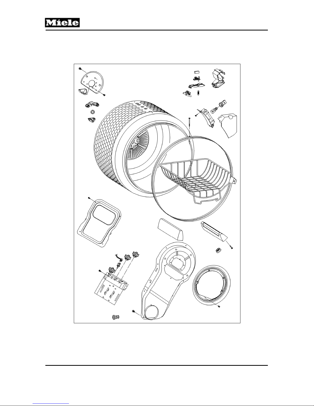
010 Casing, Front Panel ............................................................................... 12
1 Technical Data ......................................................................................... 13
4 Service ..................................................................................................... 13
4.1 Lid Removal ................................................................................. 13
4.2 Removing the Front Panel ........................................................... 14
4.3 Side Panel Removal .................................................................... 14
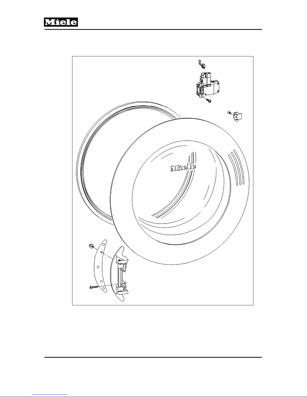
020 Door, Lock .............................................................................................. 16
1 Technical Data ......................................................................................... 17
2 Function ................................................................................................... 17
2.1 Door Lock (A2) ............................................................................. 17
4 Service ..................................................................................................... 17
4.1 Door Removal .............................................................................. 17
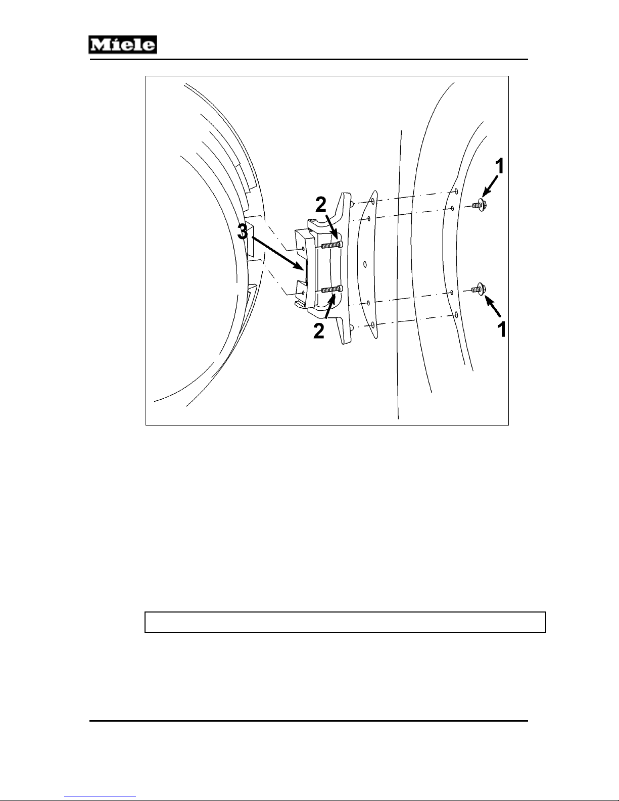
4.2 Door Hinge Removal ................................................................... 18
4.3 Installing the Door Hinge ............................................................. 18
4.4 Removing the Door Lock ............................................................. 19
030 Drum, Rear Bearing, Residual Moisture Sensor, Heater Bank ........... 20
1 Technical Data ......................................................................................... 21
2 Function ................................................................................................... 22
2.1 No-Load Detection ....................................................................... 22
2.2 Residual Moisture Measurement ................................................. 22
2.3 Heater Control ............................................................................. 23
2.4 Temperature Limiter with Manual Reset (1F1, 2F1, 3F1) ............ 23
2.5 Drying Air NTC (1R30) ................................................................. 23
2.6 Heater Bank NTC (2R30) ............................................................ 23
2.7 Interior Drum Light (H3/6) ............................................................ 23
3 Fault Repair ............................................................................................. 23
3.1 Temperature Limiter with Manual Reset (F1) Has Tripped .......... 23
4 Service ..................................................................................................... 24
4.1 Heater Bank Removal (T 980x) ................................................... 24
4.2 Rear Bearing Removal ................................................................ 25
2

T 980x/T 982x
Technical Information
4.3 Residual Moisture Sensor Removal ............................................ 27
4.4 Drum Light Removal .................................................................... 27
4.5 Lightbulb Replacement ................................................................ 27
031 Gas Heating (T 982x) .............................................................................. 28
1 Technical Data ......................................................................................... 29
2 Function ................................................................................................... 29
2.1 Gas Unit ....................................................................................... 29
4 Service ..................................................................................................... 33
4.1 Checking the Gas Burner ............................................................ 33
4.2 Removing the Gas Solenoid ........................................................ 35
4.3 Installing the Gas Solenoid Valve ................................................ 36
4.4 Removing the Gas Burner ........................................................... 38
4.5 Installing the Gas Burner ............................................................. 39
040 Motor, Fan ............................................................................................... 40
1 Technical Data ......................................................................................... 41
4 Service ..................................................................................................... 41
4.1 Fan Impeller Replacement ........................................................... 41
4.2 Motor Replacement ..................................................................... 43
050 Air Shield, Front Bearing ....................................................................... 44
1 Technical Data ......................................................................................... 45
3 Fault Repair ............................................................................................. 45
3.1 Vibration Noises from the Base Plate .......................................... 45
4 Service ..................................................................................................... 46
4.1 Air Shield Removal ...................................................................... 46
4.2 Felt Seal Replacement ................................................................ 47
090 Fascia Panel, Electronic ........................................................................ 49
1 Technical Data ......................................................................................... 50
2 Function ................................................................................................... 50
2.1 Reversing (Electric) (T 980x) ....................................................... 50
2.2 Reversing (Gas) (T 982x) ............................................................ 50
2.3 Dryer Function after a Power Interruption .................................... 50
2.4 Programming Functions ............................................................... 50
2.5 Residual Moisture Sensing .......................................................... 51
2.6 Overriding the Time Control ......................................................... 52
2.7 Insufficient Air Detection .............................................................. 52
2.8 Operating Hours Counter ............................................................. 52
2.9 Low-Voltage Detection ................................................................. 52
3 Fault Repair ............................................................................................. 53
3.1 “End” LED Is Steadily Lit .............................................................. 53
3.2 “Check Filter/Vent” LED Is Steadily Lit ........................................ 53
3.3 “Check Filter/Vent” LED Flashes Rapidly .................................... 54
3.4 “Rotary Iron” LED Flashes ........................................................... 54
3.5 “Hand Iron” LED Flashes ............................................................. 54
3.6 All Program LEDs Flash .............................................................. 55
3.7 F0: No Fault ................................................................................. 55
3.8 F1: Short Circuit in Heater Bank NTC (2R30) .............................. 55
3
T 980x/T 982x
Technical Information
3.9 F2: Open Circuit in Heater Bank NTC (2R30) ............................. 55
3.10 F3: Drying Air NTC (1R30) Short Circuit ...................................... 56
3.11 F4: Drying Air NTC (1R30) Open Circuit ..................................... 57
3.12 F50: Motor Stalls and Heater Is On for 3 Seconds ...................... 57
3.13 F55: Overriding Time Limit Exceeded ......................................... 57
3.14 F66: Air Leakage ......................................................................... 58
3.15 F98: No Gas Ignition (T 982x only) .............................................. 58
3.16 Laundry Is Overdried/F55 (Overriding Time Limit Exceeded) ..... 59
3.17 Dryer Shuts Itself Off ................................................................... 59
4 Service ..................................................................................................... 60
4.1 Programming Mode Summary ..................................................... 60
4.2 Activating/Deactivating the Demonstration Mode ........................ 62
4.3 Service Mode Summary .............................................................. 62
4.4 Removing the Fascia, Electronic and Electronic Support Panel .. 64
100 Electrical System ................................................................................... 66
1 Technical Data ......................................................................................... 67
4 Service ..................................................................................................... 67
4.1 Fuse Replacement (T 980x only) ................................................. 67
4.2 Heater Relay Removal ................................................................. 67
List of Figures
Figure D-1: T 980x Component Layout ........................................................................... 10
Figure D-2: T 982x Component Layout ........................................................................... 11
Figure 010-1: Lid Removal .............................................................................................. 13
Figure 010-2: Front Panel Removal ................................................................................ 14
Figure 010-3: Side Panel Removal ................................................................................. 15
Figure 020-1: Door Removal ........................................................................................... 18
Figure 020-2: Door Lock Removal .................................................................................. 19
Figure 030-1: Heater Bank Removal ............................................................................... 25
Figure 030-2: Bearing Housing Attachment .................................................................... 26
Figure 030-3: Rear Bearing ............................................................................................. 26
Figure 031-1: Gas Ignition Schematic ............................................................................. 30
Figure 031-2: Onset of Drying Process, Before Gas Starts to Flow ................................ 30
Figure 031-3: Drying Process, After Gas Has Started to Flow ........................................ 31
Figure 031-4: Drying Process, Flowing Gas Ignites the Flame ....................................... 31
Figure 031-5: Drying Process after Flame Has Gone Out .............................................. 32
Figure 031-6: Port for Measuring Jet Pressure ............................................................... 34
Figure 031-7: Gas Regulation Valve ............................................................................... 35
Figure 031-8: Disconnecting the Gas Regulation Valve ................................................. 36
Figure 031-9: Attaching the Gas Connecting Line to the Gas Regulation Valve ............ 36
Figure 031-10: Tightening the Gas Regulation Valve ..................................................... 37
Figure 031-11: Gas Regulation Valve ............................................................................. 37
Figure 031-12: Gas Regulation Valve ............................................................................. 38
Figure 031-13: Gas Regulation Valve ............................................................................. 39
Figure 040-1: Fan Impeller Removal ............................................................................... 42
Figure 050-1: Sealing Strip Installation ........................................................................... 45
4

T 980x/T 982x
Technical Information
Figure 050-2: Air Shield Removal ................................................................................... 46
Figure 050-3: Felt Seal Installation ................................................................................. 47
Figure 090-1: Removing the Fascia, Electronic, and Electronic Support Panel .............. 65
Figure 100-1: Fuse Replacement .................................................................................... 67
List of Tables
Table C-1: General Technical Data ................................................................................... 9
Table 010-1: Casing Technical Data ............................................................................... 13
Table 020-1: Door Technical Data .................................................................................. 17
Table 030-1: Drum Data .................................................................................................. 21
Table 030-2: Heater Data ................................................................................................ 21
Table 030-3: Heater Bank and Drying Air NTC Resistance Values ................................ 22
Table 031-1: Gas Heating Data ...................................................................................... 29
Table 040-1: Fan and Motor Data ................................................................................... 41
Table 050-1: Air Shield Data ........................................................................................... 45
Table 090-1: Technical Data ........................................................................................... 50
Table 090-2: Residual Moisture, Delicates ..................................................................... 51
Table 090-3: Values for Low-Voltage Detection .............................................................. 52
Table 090-4: Programming Mode Summary ................................................................... 61
Table 090-5: Service Mode Summary ............................................................................. 64
Table 100-1: Electrical System Data ............................................................................... 67
5

Technical Information
A Warning and Safety Instructions
1 General Information
Danger!
Danger of high voltages when working on small components.
In a single-board control, as in this appliance's electronic (EPWL 3xx),
there is no structural galvanic potential disconnection to the power supply.
Therefore, be careful when working on small components, as they may
be carrying voltage if the dryer is not disconnected completely from its
power supply.
Components with sharp edges may stick out. Wear protective gloves and
goggles and use edge shields to prevent cuts by sharp-edged components.
Note:
All repairs should be performed by a trained technician in strict
accordance with national, state and local codes. Any repairs or
maintenance performed by unqualified personnel could be dangerous.
When servicing, modifying, testing or maintaining appliances, all
applicable laws, regulations and accident prevention guidelines must be
observed.
T 980x/T 982x
After work has been completed, a visual as well as an operational check
should always be performed.
After work has been completed, do a touch current measurement on
machines with a ground connection on all accessible conductive parts
that are not grounded.
Before starting any service work, disconnect the dryer from its power
source. Even with the appliance switched off, voltage may exist on some
components.
2 Gas Dryers
Warning!
Before starting any service or repair work, it is essential to disconnect the
dryer from its gas supply.
Service work may only be performed by a technician trained in gas
technology, and in keeping with all relevant safety standards.
Prior to the start of service work, check all gas lines and components to
make sure that they are sealed.
If there is a gas odor, shut the gas tap. Avoid sparks or any fire source,
and air out all rooms.
6

T 980x/T 982x
Technical Information
3 Fire Danger Due To Excessive Lint
Danger!
The dryer must not be operated if there are leaks in the air shield, such as
those caused by a defective seal.
If the dryer is operated regardless of these leaks, this will result in heavy
lint in the appliance interior. Moisture can make this excessive lint soggy,
which will lead to electrical short circuits and possibly fire.
Indications of excessive lint: a poorly maintained dryer, long running time
(fixed maximum time has been exceeded), water under the fascia panel.
Remedy:
- Remove all lint from the dryer.
- Find and repair leaks.
4 Restoring the Ground Connection after Dismantling the
Front and Side Panels
The ground connection for laundry-care appliances is established via
screws: raised-head screws with teeth or serrated washers underneath
connect the ground lead to the interference-suppression filter, the front
panel, the side panels and the housing frame. These screws are different
from the rest of the appliance screws in their diameter, type of thread, and
type and material of the washer.
The ground connection is made only if the ground screws are screwed
into their correct positions during reassembly.
When dismantling the front and side panels, mark the positions of the
ground screws. During reassembly, screw the ground screws into these
same positions.
To check the proper screw positions, measure the resistance of the
ground connection loop.
7
Technical Information
B Modification History
When Who What
6/3/2010 Jessica Naples T 9802 added (reflected in “T 980x”)
8/27/2009 Jessica Naples Conversion for Website
3/11/2009 Liane Westerhelweg Version 5
5/16/2008 Liane Westerhelweg Version 4
5/14/2008 Liane Westerhelweg Version 3
12/8/2006 Olaf Meyer zu Drewer Version 2
11/30/2006 Olaf Meyer zu Drewer Initial compilation
T 980x/T 982x
8
T 980x/T 982x
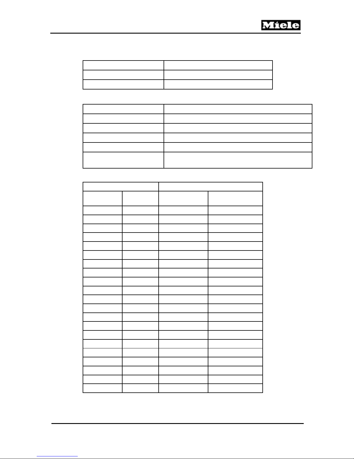
C Technical Data
T 980x T 982x
Dimensions
Shipping
dimensions
Shipping weight
Required voltage
Frequency
Connected load
(electric)
Natural gas output
Natural gas - net
pressure
Exhaust pipe
(vented dryers
only)
Washer/dryer
stack
Under-counter
Washer/dryer
stand
Liquid propane
conversion
PC interface
RemoteVision
Table C-1: General Technical Data
Electric Heating Gas Heating
2NAC 240V (208V) 1NAC 120V
Technical Information
Height x width x depth: 39” x 27” x 30”
Height x width x depth: 42” x 30” x 32”
Approx. 165 lbs
60Hz
5.8kW 0.3kW
N/A 1076 BTU/ft3
N/A Supply pressure 4oz/in2
N/A
Optional
N/A Optional
Compatible, optional accessory
Connecting pipe nominal
diameter 4”
No
No
Yes
9
Technical Information
D Layout of Electrical Components
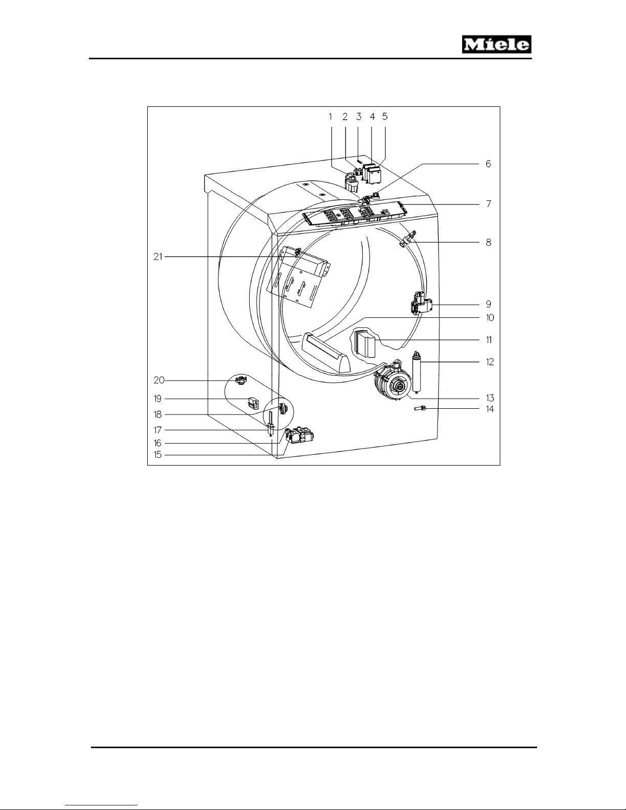
1 T 980x
T 980x/T 982x
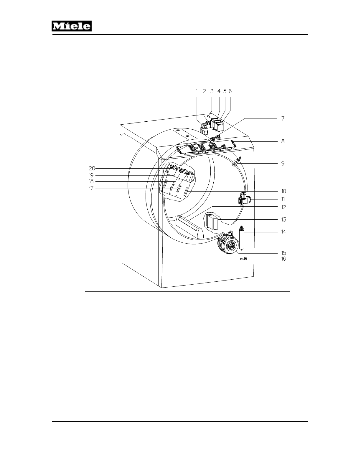
Figure D-1: T 980x Component Layout
1 (Z/1) Interference suppression capacitor 11 (A2) Door lock
2 (X3/1) Terminal block 12 (B3/1) Residual moisture sensor - Drum rib
3 (F2) Fuse 13 (WLAN) RemoteVision (optional)
4 (1K1/1) Heater relay 14 (C5) Motor capacitor
5 (2K1/1) Heater relay 15 (M5) Motor
6 (3K1/1) Heater relay 16 (1R30) Drying air NTC
7 (B3/1) Residual moisture sensor 17 (3F1) Temperature limiter w/manual reset
8 (1N1) Electronic (EPWL) 18 (2F1) Temperature limiter w/manual reset
9 (H3/6) Drum light 19 (2R30) Heater bank NTC
10 (R1, R2, R3) Heater bank 20 (1F1) Temperature limiter w/manual reset
10
T 980x/T 982x
2 T 982x
Technical Information
Figure D-2: T 982x Component Layout
1 (Z/1) Interference suppression capacitor 12 (C5) Motor capacitor
2 (X3/1) Terminal block 13 (M5) Motor
3 (F2) Fuse 14 (1R30) Drying air NTC
4 (1K1/1) Heater relay 15 (Y57/1) Gas solenoid
5 (2K1/1) Heater relay 16 (Y57/2) Gas solenoid
6 (B3/1) Residual moisture sensor 17 (E1/1) Igniter electrode
7 (1N1) Electronic (EPWL)
8 (H3/6) Drum light 19 (B1/16)
9 (A2) Door lock 20 (1F1) Temperature limiter w/manual reset
10 (B3/1) Residual moisture sensor - Drum rib 21 (2R30) Heater bank NTC
11 (WLAN) RemoteVision (optional)
18 (2F1) Temperature limiter flame flashback
w/manual reset
Flame sensor (radiant output sensor)
11
Technical Information
010 Casing, Front Panel
T 980x/T 982x
12

T 980x/T 982x
1 Technical Data
Design
Table 010-1: Casing Technical Data
Upright, frame construction, side walls
embossed for reinforcement
4 Service
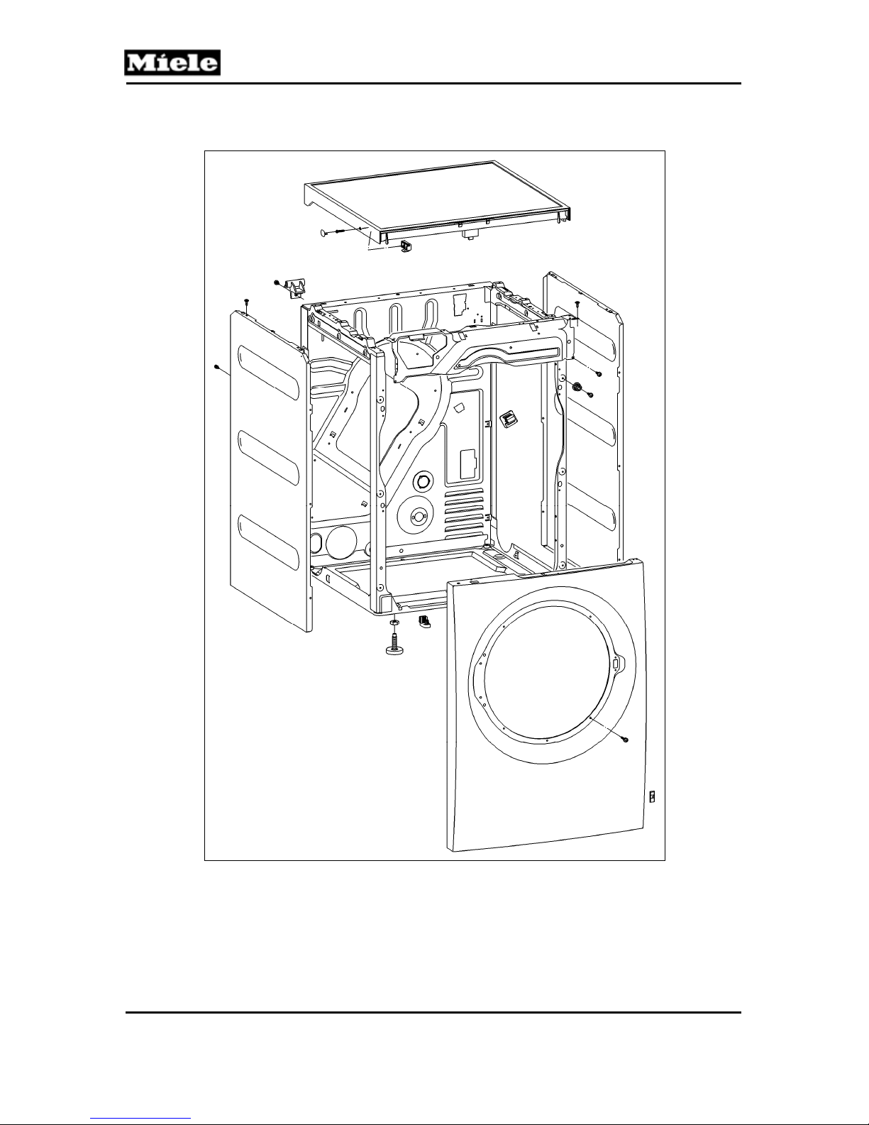
4.1 Lid Removal
1. Disconnect the machine from the power supply.
2. Remove the screw caps on the sides. See Figure 010-1.
3. Loosen the T20 screws a maximum of 5 turns. Do not unscrew the
screws completely.
4. Press in on the screws.
5. Lift the lid at the front and slide it back to release it from its retainers.
Take the lid off.
Technical Information
Figure 010-1: Lid Removal
13
Technical Information
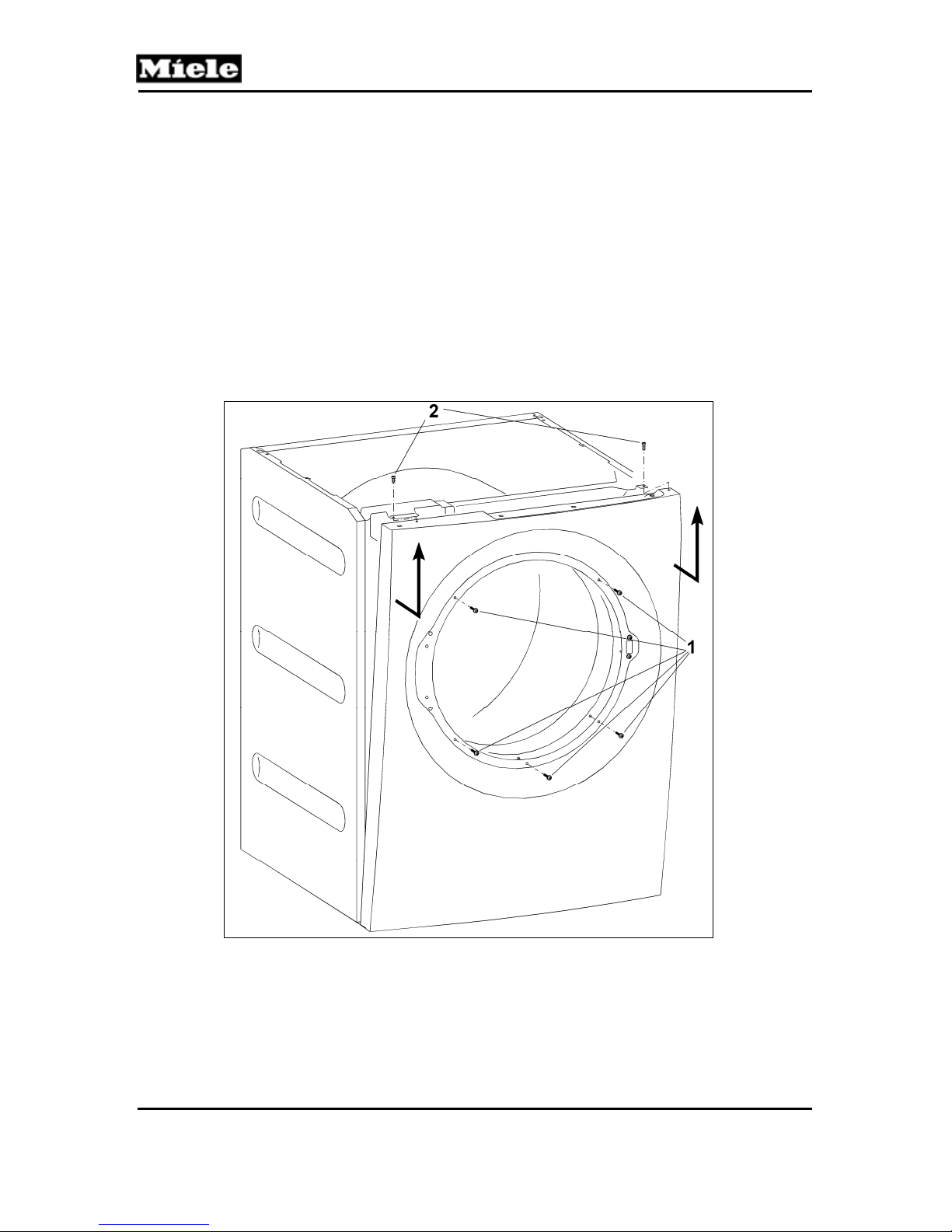
4.2 Removing the Front Panel
1. Disconnect the machine from the power supply.
2. Remove the dryer lid; refer to Section 010-4.1.
3. Remove the fascia, the electronic, and the electronic's support panel; refer
to Section 090-4.4.
4. Open the door.
5. Remove the five T20 screws securing the front of the front panel. See
Figure 010-2, Item 1.
6. Close the door.
7. Remove the two T20 screws securing the top of the front panel. See
Figure 010-2, Item 2.
8. Disconnect the door lock Molex connection.
9. Pull the front panel upwards to remove.
T 980x/T 982x
Figure 010-2: Front Panel Removal
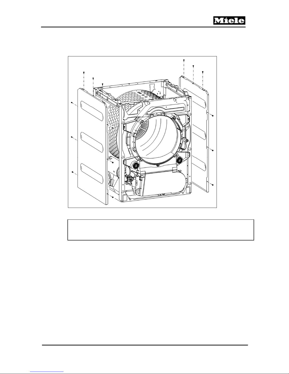
4.3 Side Panel Removal
1. Disconnect the machine from the power supply.
2. Remove the lid; refer to Section 010-4.1.
3. Remove the front panel; refer to Section 010-4.2.
14
T 980x/T 982x
4. Remove the side panel retaining screws (nine T20s per panel). See
5. Take the side panel(s) off.
Technical Information
Figure 010-3.
Figure 010-3: Side Panel Removal
Note:
When re-installing the side panels, ensure that the screws with serrated
washers (ground screws) are installed in the correct positions.
15
Technical Information
020 Door, Lock
T 980x/T 982x
16
T 980x/T 982x
1 Technical Data
Door
Lock
Table 020-1: Door Technical Data
2 Function
2.1 Door Lock (A2)
Pull the door open.
An open door is registered by a microswitch in the door lock
(drum door open = contact open).
4 Service
4.1 Door Removal
1. Disconnect the appliance from the power supply.
2. Take off the front panel; refer to Section 010-4.2.
3. Turn the front panel around and remove the two locknuts (Figure 020-1,
Item 1) with an 8-millimeter nut driver or wrench.
4. Carefully separate the door from the front panel.
Technical Information
Porthole door. Door hinge is on the left
and cannot be reversed.
Manual pull-open lock.
Door lock contact switch (A2). Drum
door open = contact open.
17
Technical Information
T 980x/T 982x
Figure 020-1: Door Removal
4.2 Door Hinge Removal
1. Disconnect the appliance from the power supply.
2. Remove the door; refer to Section 020-4.1.
3. Turn the door over; lay it on a soft mat or cloth so that the door glass
does not get damaged.
4. Remove the two T20 bolts securing the hinge to the door (Figure 020-1, Item 2).
5. Insert a flathead screwdriver under the bottom of the hinge and lift up to
release the hinge from its base on the door (Figure 020-1, Item 3).
4.3 Installing the Door Hinge
1. Open the hinge and slide it back onto its base.
2. Close the hinge and re-secure it with the two T20 bolts.
Note: Make sure that the hinge lines up with the welded seam of the door seal.
18
T 980x/T 982x
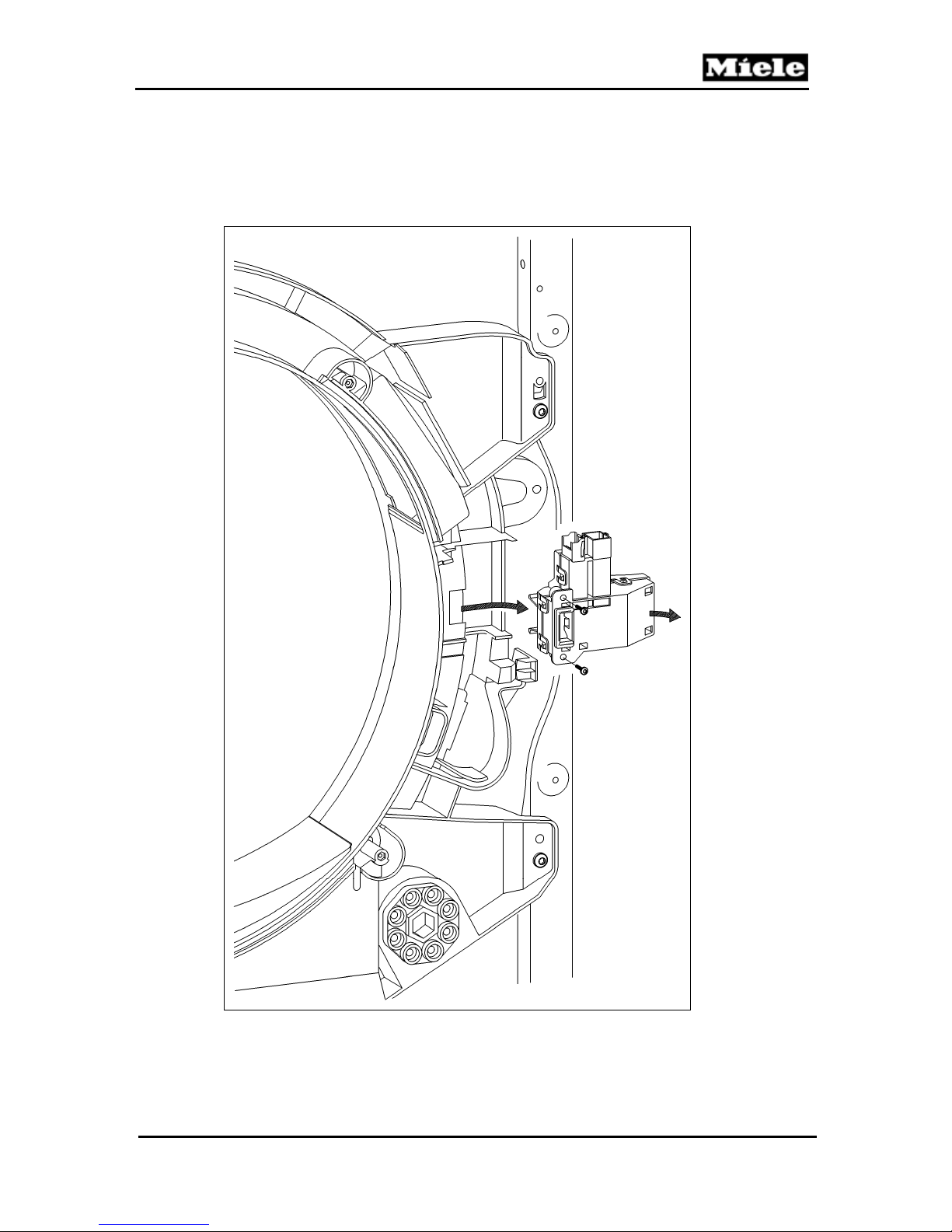
4.4 Removing the Door Lock
1. Disconnect the appliance from the power supply.
2. Take off the front panel; refer to Section 010-4.2.
3. Remove the two T20 screws securing the door lock to the front panel.
See Figure 020-2.
Technical Information
Figure 020-2: Door Lock Removal
19
T 980x/T 982x
Technical Information
030 Drum, Rear Bearing, Residual Moisture Sensor,
Heater Bank
20
T 980x/T 982x
1 Technical Data
Maximum load
Drum volume
Drum speed
Table 030-1: Drum Data
Heating mode
Heater type
Heater output
Temperature sensor
Temperature limiter
Drum light (H3/6)
Table 030-2: Heater Data
Temperature Resistance (kΩ)
°F °C
32 0 340 38.0
41 5 261 29.7
50 10 203 23.4
59 15 159 18.6
68 20 126 14.9
77 25 100 12.0
86 30 80.2 9.73
95 35 64.8 7.96
104 40 52.7 6.55
113 45 43.1 5.42
122 50 35.5 4.52
131 55 29.4 3.78
140 60 24.5 3.19
149 65 20.5 2.70
158 70 17.3 2.29
167 75 14.6 1.96
176 80 12.5 1.68
185 85 10.6 1.45
194 90 9.13 1.25
199 93 8.34 1.15
203 95 7.86 1.09
Technical Information
17.6 lbs (8 kg)
48 gal (180L)
48 rpm
Electric; for gas, refer to Table 031-1.
Duct heater bank (R1, R2, R3); 3-filament
5.2kW (1.90kW, 1.70kW, 1.60kW)
Heater bank NTC (2R30)
3 x 3/4“ temperature limiter (F1) with manual reset, 16A
E 14 bayonet closure, activation via relay on the
electronic (EPWL). USA: 120V, 15W
Heater bank NTC
(2R30)
Drying air NTC
(1R30)
21
 Loading...