

Installation plan
Washer-extractor
PW 6107 D
en - GB
06.15 M.-Nr. 10 303 250 / 01

2
M.-Nr. 10 303 250 / 01


Technical datasheet
Washer-extractor:
Heating type:
PW 6107
Steam (D)
Legend:
Circled, bold-type abbreviations:
Connection required
en - GB
Abbreviations surrounded by broken circle:
Connection optional or required, depending on model
UM
Miele plinth
UO 6010 (UO = open plinth)
Height
mm
144 Width
mm
780
Depth
mm
789
UG 6010 (UG = Box plinth)
Height
mm
144
Width
mm
800
Depth
mm
799
UO 6020 (UO = open plinth)
Height
mm
300
Width
mm
780
Depth
mm
789
UG 6010-30 (UG = Box plinth)
Height
mm
300
Width
mm
800
Depth
mm
799
BS
Concrete plinth
Recommended height
mm
150
Minimum height
mm
100
Plinth width min.
mm
950
Min. plinth depth
mm
910
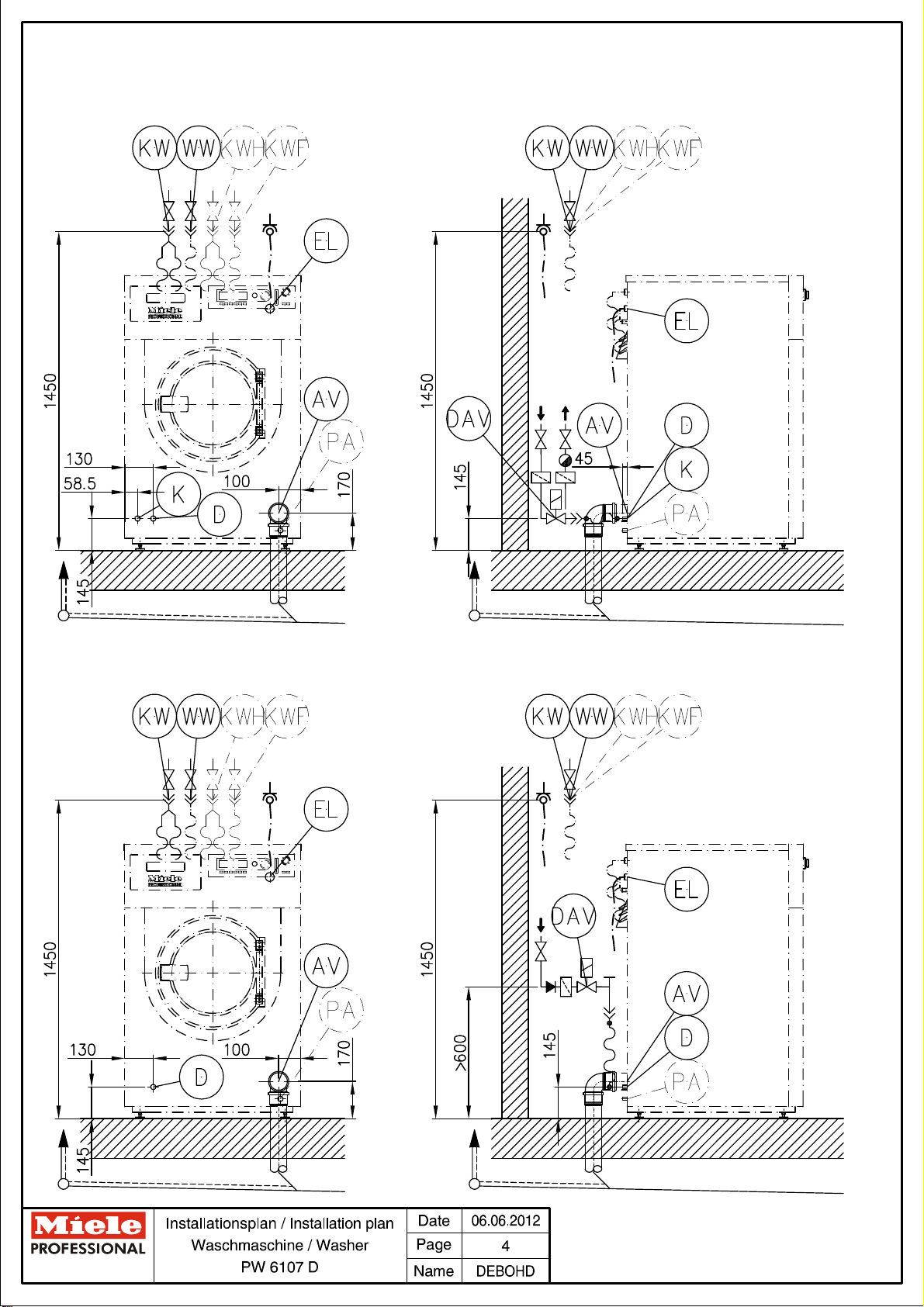
DAV
Steam
connection valve
The steam connection valve to regulate the steam supply
must be provided on site.
The following valves can be ordered separately as electric
steam valves or as pneumatic steam valves.
Electric steam valve (ELD 01)
Regulatable steam pressure
kPa
200 - 1000
Connection gauge
Inch
½"
Voltage
V
1N AC 230
Frequency
Hz
50 - 60
Pneumatic steam valve (PND)
Regulatable steam pressure
kPa
0 - 1000
Connection gauge
Inch
½"
Supply point and pneumatic valve controls must be provided
on site.
Options / Accessories:
Technisches Datenblatt / Technical datasheet: PW 6107 D
Datum / Date: 24.04.2013 Seite / Page: 7

Electrical
connection
1. Standard voltage (standard version)
V 3N AC 380 - 415
Frequency
Hz
50 - 60 Connected load
kW
2.3
Fuse rating
A 3 × 16
Connection cable, min. gauge
mm²
5 × 1.5
Connection cable not supplied (to be ordered
separately)
Variations in the following countries:
1. Standard voltage (standard version)
V 3 AC 220 - 240
Frequency
Hz
60 Connected load
kW
2.3
Fuse rating
A 3 × 15
Connection cable, min. gauge
mm²
4 × 1.5
Connection cable not supplied (to be ordered
separately)
Alternative voltage (convertible)
V 3 AC 208
Frequency
Hz
60
Connected load
kW
2.3
Fuse rating
A 3 × 15
Connection cable, min. gauge
mm²
4 × 1.5
Connection cable not supplied (to be ordered
separately)
The electrical connection may only be made to an electrical
system provided in accordance with all appropriate local and
national legislation and regulations. In addition, all regulations
of the appropriate utility supply companies and standards
relating to safety, and all applicable valid regulations and
technical standards must be complied with!
Electrical connection is the responsibility of a qualified
electrician.
The machine can be either hard-wired or connected via a
socket in compliance with IEC 60309-1. Wall socket or mains
isolator must be accessible after installation.
It is always recommended to make electrical connection via a
plug and socket so that electrical safety checks, e.g. during
repair or service work, can be carried out easily.
If it is necessary to install a residual current device (RCD) in
accordance with the local regulations, a residual current
device type B must be used.
Equipotential
bonding
Connection with male thread
mm
10 × 35
for washers and nuts
M
10
Fasteners such as washers and nuts are not provided.
If necessary, equipotential bonding with good galvanic
contact must be guaranteed in compliance with all applicable
local and national installation codes.
Steam
connection
Steam pressure (Low pressure steam)
kPa
50
Direct
Boiling point
°C
120
Mass flow (max. delivery)
kg/h
31
Heater rating
kW
18
Steam pressure (high-pressure steam)
kPa
50 - 400
Boiling point
°C
152
Mass flow (max. delivery)
kg/h
47
Heater rating
kW
27
On-site threaded union
Inch
½" female thread
Steam valve, filter, non-return valve and steam shut-off valve
must be provided on site.
The steam valve should be installed in such a way as to
prevent any wash liquor from the machine from flowing back
into the valve.
Machine connections:
Technisches Datenblatt / Technical datasheet: PW 6107 D
Datum / Date: 24.04.2013 Seite / Page: 8

Steam
connection
Steam pressure
kPa
400 - 1000
Indirect
Boiling point
°C
152 - 184
Mass flow (max. delivery)
kg/h
67
Heater rating
kW
37
On-site threaded union
Inch
½" female thread
Steam valve, filter, non-return valve and steam shut-off valve
must be provided on site.
Steam valve supply lead length
mm
500
The supply lead for the electric steam valve is included.
The steam valve should be installed close to the steam
connection.
Installation instructions for steam-heated washer-extractors
apply throughout.
Condensate
connection
On-site threaded union
Inch
½" female thread
A shut-off device and condensate trap must be provided on
site.
The condensate separator must be installed such that when
the system is not operating, the heater bank is completely
emptied. This means that no condensate may remain in the
heater bank.
Cold water
(softened water)
Min. water pressure/flow pressure
kPa
100
Max. water pressure/flow pressure
kPa
1000
Flow rate, max.
l/min
26
Max. throughput (if hot and raw water supply is not available)
l/min
42
2 connection hoses with ¾" threaded union incl. Y-piece
(¾" / 1") supplied.
On-site threaded union in accordance with DIN 44991 (flat
sealing)
Inch
1" male thread
Connection hose length
mm
1500
Average water consumption in standard programme (60°
Cottons) when connected to cold, hot and raw water supplies.
l/h
Approx. 76
In the absence of a hot water supply, add sufficient water to
reach the required amount.
If connecting to raw water, subtract water requirement from
cold water.
Hot water
(softened water)
Max. water intake temperature
°C
70
Min. water pressure/flow pressure
kPa
100
Max. water pressure/flow pressure
kPa
1000
Max. flow rate
l/min
16
1 inlet hose with ¾" threaded union provided.
On-site threaded union in accordance with DIN 44991 (flat
sealing)
Inch
¾" male thread
Connection hose length
mm
1500
Average water consumption in standard programme (60°
Cottons) when connected to cold, hot and raw water supplies.
l/h
Approx. 82
If no hot water supply available, connect hot water hose to
cold water supply!
Cold water
Raw water
Min. water pressure/flow pressure
kPa
100
Max. water pressure/flow pressure
kPa
1000
Flow rate, max.
l/min
32
2 connection hoses with ¾" threaded union including Y-piece
(¾" / 1") included in optional kit.
On-site threaded union in accordance with DIN 44991 (flat
sealing)
Inch
1" male thread
Connection hose length
mm
1500
Average water consumption in standard programme (60°
Cottons) when connected to cold, hot and raw water supplies.
l/h
Approx. 48
Technisches Datenblatt / Technical datasheet: PW 6107 D
Datum / Date: 24.04.2013 Seite / Page: 9

Cold water
Liquid dispensing
Min. water pressure/flow pressure
kPa
100
Max. water pressure/flow pressure
kPa
1000
Flow rate, max.
l/min
5.5
1 supply hose with ¾" threaded union included in optional kit.
On-site threaded union in accordance with DIN 44991 (flat
sealing)
Inch
¾" male thread
Connection hose length
mm
1500
Waste water
Drain valve
Max. water temperature
°C
95
Machine-side drain connection (ext. diameter)
mm
75 [DN 70]
On-site drain connection (int. diameter)
mm
75 [DN 70
connection]
Max. transient flow rate
l/min
200
Vented collector line required; if insufficient venting, use Miele
installation kit, Mat. no. 05238090.
When several machines are connected, ensure that the
manifold is of a sufficient diameter.
Securing of
machine
Without plinth
The machine must be adequately anchored to the floor!
Fastening material included with unit:
2 × angled brackets (from transport strut)
2 × wood screws DIN 571 (Ø × length)
mm
8 x 80
2 × rawl plugs (Ø × length)
mm
12 x 60
The installation surface must be sufficiently stable and solid.
The fastening material provided is designed for securing the
machine to a concrete floor only. Fasteners for other floor
types must be provided on site.
On concrete plinth
The machine must be adequately anchored to the floor!
Fastening material included with unit:
2 × angled brackets (from transport strut)
2 × wood screws DIN 571 (Ø × length)
mm
8 x 80
2 × rawl plugs (Ø × length)
mm
12 x 60
The quality of the concrete and its strength must be assessed
according to the machine load. A secure joint between a
concrete plinth and the floor must be guaranteed.
Miele plinth
A plinth must be securely bolted to the floor!
Fasteners included with plinth
4 × wood screws DIN 571 (Ø × length)
mm
8 x 80
4 × rawl plugs (Ø × length)
mm
12 x 60
Installation of machine and plinth must be in accordance with
the installation instructions provided.
Technisches Datenblatt / Technical datasheet: PW 6107 D
Datum / Date: 24.04.2013 Seite / Page: 10

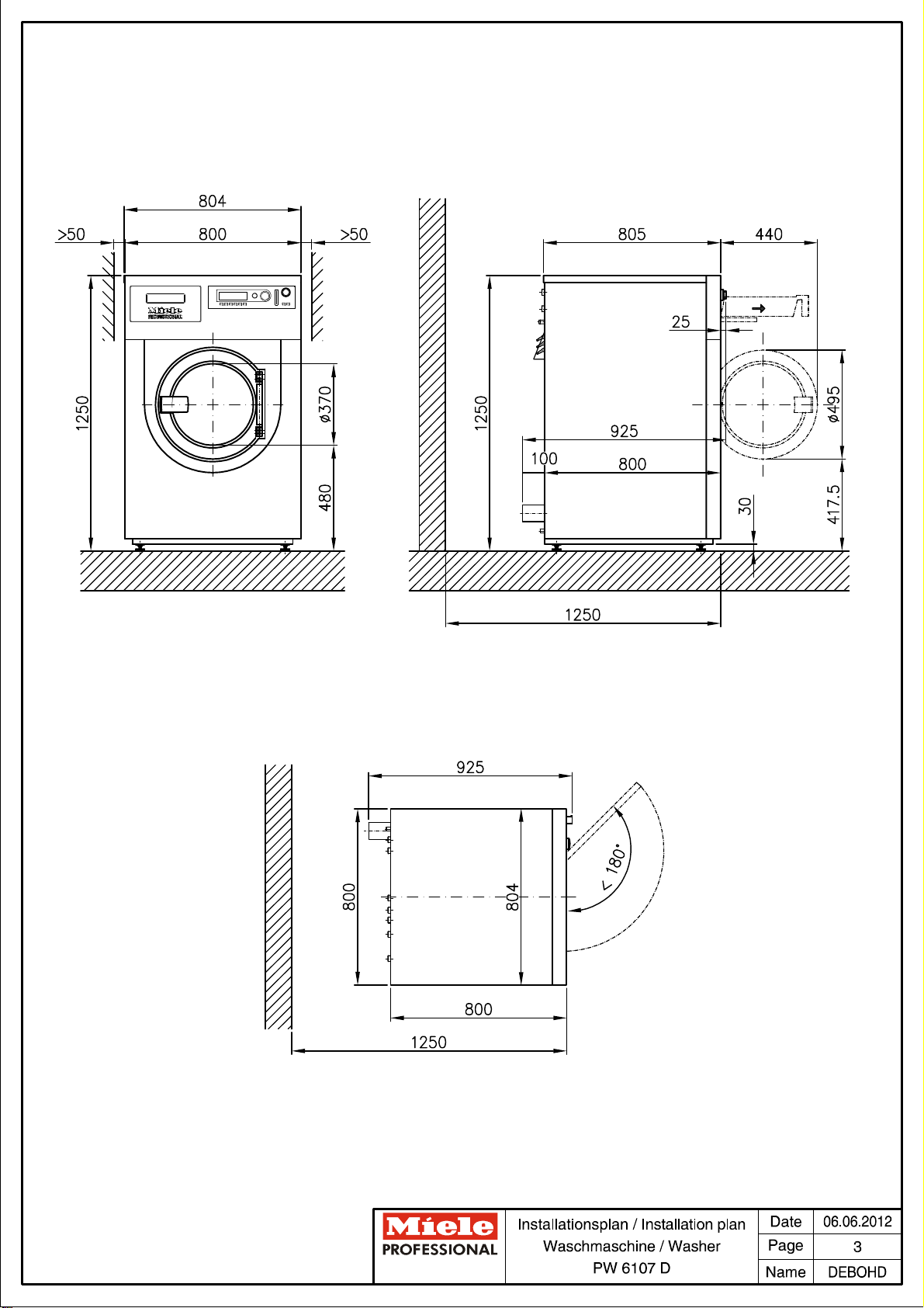
Machine data
Machine width
mm
804
Machine depth
mm
925
Machine height
mm
1250
Machine width
mm
800
Casing depth
mm
800
Min. access width
mm
810
Recommended distance from opposite wall (to front of
machine)
mm
1250
Min. wall gap (to rear edge of lid)
mm
400
Net weight
kg
320
Max. floor load in operation
N
3970
Max. static floor load
N
3522
Max dynamic floor load
N
448
Max. drum rotation frequency
Hz
20
Average heat dissipation to installation site
(depending on ambient temperature and programme
selected)
W
1050
Sound pressure level (re 20 mPA),
(distance 1 m and 1.6 m above floor)
dB(A)
66
Installation should only be performed by qualified fitters in accordance with valid regulations, relevant standards and health
and safety codes!
It is important to comply with installation instructions when installing machines! All rights reserved! Dimensions in mm.
Technisches Datenblatt / Technical datasheet: PW 6107 D
Datum / Date: 24.04.2013 Seite / Page: 11
 Loading...