

Page 1
Installation plan
Heat pump dryer
PT 8203 SL WP
To avoid the risk of accidents or damage to the
machine, it is essential to read these instructions
before it is installed and used for the first time.
en - GB, IE
M.-Nr. 10 534 370
Page 2

2 PT 8203 SL WP
Page 3

Contents
Installation and planning notes..........................................................................................4
Installation requirements ....................................................................................................... 4
General operating conditions ................................................................................................ 4
Installation ............................................................................................................................. 4
Levelling the machine............................................................................................................ 5
Securing the dryer against slippage...................................................................................... 6
Guide to the machine ............................................................................................................ 6
Electrical connection ............................................................................................................. 7
Air intake vent........................................................................................................................ 8
Air outlet vent ........................................................................................................................ 8
Condensate drainage ............................................................................................................ 8
Accessories ........................................................................................................................... 9
Communication module XKM for RS232 interface ......................................................... 9
Technical drawings -dimensions in mm.........................................................................10
Dimensions.......................................................................................................................... 10
Installation ........................................................................................................................... 11
Set up .................................................................................................................................. 12
Technical data....................................................................................................................13
Electrical data...................................................................................................................... 13
Voltage variant 3N AC 400V, 50Hz............................................................................... 13
Condensate drainage .......................................................................................................... 13
Transport data ..................................................................................................................... 13
Installation data ................................................................................................................... 13
3
Page 4
Installation and planning notes
Installation requirements
The dryer must only be set up by a Miele authorised and trained
service technician or an authorised dealer.
This dryer must be installed in accordance with all relevant regula-
tions and standards. Local energy supplier regulations must also be
observed.
This dryer must only be operated in a room that has sufficient vent-
ilation and which is frost-free.
General operating conditions
This dryer is intended only for use in a commercial environment and
must only be operated indoors.
Permissible ambient temperature:2 °C to 43 °C
The electrical components of this dryer comply with safety standards IEC/DINEN60335-1 and DINEN50570.
Installation
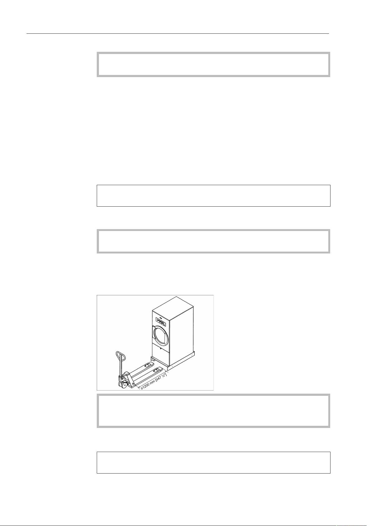
This dryer must only be transported with the transport safety
device fitted.
Transport the dryer to its installation site using a suitable pallet truck
and then remove the transport safety device. Keep this device in a
safe place for refitting should the dryer need to be moved in the future (e.g when moving to a new site).
When transporting the dryer be aware of its total height.
Be careful when transporting it on a pallet truck that it does not tip
up.
The dryer must be set up on a level and firm surface, with a minimum
load bearing capacity of2220 N.
The floor load created by the dryer is concentrated and transferred
to the installation footprint via the machine feet.
4 PT 8203 SL WP
Page 5
Installation and planning notes
To ensure easy access in the event of future servicing, please maintain a gap of at least 500 mm behind the dryer.
After setting up the dryer please let it stand for approx. 30 minutes
before using it for the first time. If the heat-pump unit was tilted by
an angle of 30° before the dryer was set up, or if it was subjected
to excessive movement, please let the dryer stand for 24hours before using it.
Otherwise the heat pump can suffer damage.
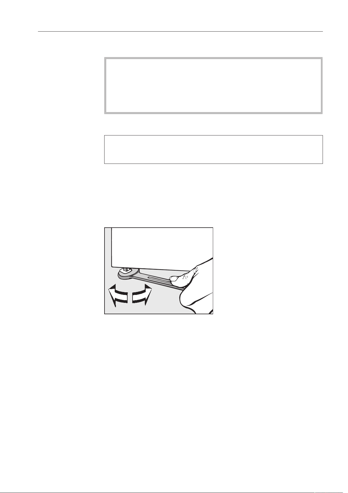
Levelling the machine
To ensure the dryer functions correctly and energy efficiently, it must
stand securely and evenly on the floor with all four feet. Any unevenness in the floor can be compensated for by adjusting the feet.
Loosen the counter nuts on the feet using a spanner.
With the assistance of a spirit level align the dryer horizontally and
vertically by adjusting the height of the feet.
After aligning the dryer tighten the counter nuts by turning them in a
clockwise direction with a spanner. This will prevent the feet from
adjusting themselves.
PT 8203 SL WP 5
Page 6

Installation and planning notes
Securing the dryer against slippage
The dryer can be secured to the floor by fitting the clamps supplied
over the feet.
Fittings supplied are for installation on a concrete floor. For other
types of flooring please purchase suitable fitting materials separately.
Guide to the machine
a
Control panel
with controls
b
Door
c
Fluff filter compartment cover
d
Air intake vent
e
Machine feet
Qty 4, adjustable
6 PT 8203 SL WP
f
Electrical connection
with cable gland
g
Communication module slot
for XKMRS232
Optional accessory
h
Condensate drainage
i
Air outlet vent
j
Data plate
Page 7

Installation and planning notes
Electrical connection
The electrical connection must be carried out by a qualified electrician who must ensure that all electrical work is carried out in accordance with applicable electrical regulations and standards (BS
7671 in the UK).
This dryer must be connected to an electrical mains supply that
complies with local and national regulations. Please also observe
your insurance and energy supplier's regulations as well as any health
and safety at work regulations.
The required voltage, power consumption and specifications for
external fusing are quoted on the data plate on the dryer. Ensure that
the supply voltage complies with the voltage quoted on the data plate
before connecting the dryer to the mains.
Connection to a supply voltage other than the one quoted on the
data plate can lead to functional faults and damage the dryer.
If more than one voltage is quoted on the data plate, the dryer can
be converted for connection to the voltages stated.
Conversion to a different voltage must only be carried out by a Miele
Service engineer or by an authorised Service Dealer. The wiring instructions given on the wiring diagram must be followed.
This dryer can either be hard-wired or connected via a plug and
socket that complies with IEC60309-1.
For hard-wired machines connection should be made via a suitable
mains switch with all-pole isolation which, when in the off position,
ensures a 3 mm gap between all open contacts. These include circuit breakers, fuses and relays (IEC/EN60947).
If the mains supply cannot be permanently disconnected, the isolator
switch (including plug and socket) must be safeguarded against being switched on either unintentionally or without authorisation.
Tip: We recommend connection to the power supply via a suitable IP
44 plug and socket which must be easily accessible for servicing and
maintenance work after the machine has been installed. An electrical
safety test must be carried out after installation and after any service
work.
If it is necessary to install a residual current device (RCD) in ac-
cordance with the local regulations, a residual current device type A
can be used.
Equipotential bonding with a good contact connection should be
carried out in accordance with local and national installation regulations. Equipotential bonding with a leakage current of >10mA should
be carried out. Accessories required for equipotential bonding (washers and nuts) are not supplied with the machine.
PT 8203 SL WP 7
Page 8

Installation and planning notes
Air intake vent
Air intake for the condenser is via an air intake vent at the front of
the dryer. Air is taken from the room in which the dryer is installed.
A fluff filter is located in the air intake vent in the dryer. This must be
regularly cleaned by hand.
The air intake vent must be kept clear. It must not be covered.
Air outlet vent
Because the heat-pump dryer operates with a closed air circuit, separate exhaust ducting is not required.
The warm air expelled from the machine as a result of cooling down
the heat-exchanger warms the room air. It is essential to ensure the
room has adequate ventilation, e.g. by providing ventilation openings
that cannot be closed whilst the machine is in use. Insufficient ventilation in the room increases the time required for drying, which in turn
will increase the amount of energy required for the drying process.
The ventilation openings must, on no account, be closed or
blocked by objects.
Condensate drainage
The heat-pump in this dryer operates on the principle of condensation. A separate floor drain must be provided in the installation room
for condensate from the drying process.
The condensate drainage point is located at the back of the heatpump dryer. The condensate must be drained via a downwards pointing DN30 pipe to the floor drain.
Ensure that condensate cannot backflow into the dryer. A non-return valve, available as an optional accessory, can be fitted if necessary.
Any condensate that gets back into the machine can cause damage.
8 PT 8203 SL WP
Page 9

Installation and planning notes
Accessories
Accessory or spare parts may only be connected or built-in to this
machine if they are expressly approved for such use by Miele.
If non-Miele parts are used, guarantee, performance and product liability claims may be invalidated.
Communication
module XKM for
RS232 interface
The serial interface RS-232 can be retrofitted to the dryer via an
XKMRS232 (optional accessory available from Miele). This communication module must only be used with MieleProfessionalmachines
that are fitted with an appropriate slot for the module.
The data interface provided via communication module
XKMRS232 complies with SELV (Safety Extra Low Voltage) in accordance with EN60950.
Appliances connected to this interface must also be SELV compliant.
Communication module XKMRS232 is supplied with a connection
cable and a D-sub-connector.
PT 8203 SL WP 9
Page 10

Technical drawings -dimensions in mm
1074
Dimensions
10 PT 8203 SL WP
Page 11

Installation
50
618 90
1700
200
500
>100
254
200
1700
Technical drawings -dimensions in mm
a
Electrical connection
b
Condensate drainage
PT 8203 SL WP 11
Page 12

Technical drawings -dimensions in mm
3
3
3
Set up
c
Anchoring point (optional)
12 PT 8203 SL WP
Page 13

Technical data
Electrical data
Voltage variant 3N AC 400V, 50Hz
Voltage 3N AC 400 V
Frequency 50 Hz
Fuse rating 3 x 16 A
Total connected load 2,6 kW
Current draw 3 x 8,5 A
Connection cable, min. cross-section 5 x 2,5 mm²
Cable gland M25 x 1,5
Condensate drainage
External diameter 32 mm
Length (from the rear panel) 50 mm
Transport data
Packaging width 800 mm
Packaging height 1810 mm
Packaging depth 1180 mm
Volume 1651,8 l
Weight (gross) 213 kg
Installation data
Overall machine width 711 mm
Overall machine height 1800 mm
Overall machine depth 1075 mm
Casing width (without add-on components) 708 mm
Casing height (without add-on components) 1800 mm
Casing depth (without add-on components) 999 mm
Machine weight (net) 202 kg
Max. floor load in operation 2220 N
Minimum width of loading aperture (internal width) 725 mm
Recommended distance between front of machine and the wall 1500 mm
Average heat dissipation rate to installation site 650 W
Emission sound pressure level in accordance with EN ISO 11204 57 dB (A)
Noise power level in accordance with EN ISO 9614-2 71 dB (A)
PT 8203 SL WP 13
Page 14

Carl-Miele-Straße 29, 33332 Gütersloh, Germany
Miele & Cie. KG
Manufacturer:
Malaysia
Miele Sdn Bhd
Suite 12-2, Level 12
Menara Sapura Kencana Petroleum
Solaris Dutamas No. 1, Jalan Dutamas 1
50480 Kuala Lumpur, Malaysia
Phone: +603-6209-0288
Fax: +603-6205-3768
Miele New Zealand Limited
IRD 98 463 631
Level 2, 10 College Hill
Freemans Bay, Auckland 1011, NZ
Tel: 0800 464 353
Internet: www.miele-professional.com.au
E-mail: info@miele-professional.com.au
New Zealand
Miele Pte. Ltd.
163 Penang Road
# 04 - 03 Winsland House II
Singapore 238463
Tel: +65 6735 1191, Fax: +65 6735 1161
E-Mail: info@miele.com.sg
Internet: www.miele.sg
Singapore
Miele (Pty) Ltd
63 Peter Place, Bryanston 2194
P.O. Box 69434, Bryanston 2021
Tel: (011) 875 9000, Fax: (011) 875 9035
E-mail: info@miele.co.za
Internet: www.miele.co.za
South Africa
Miele Appliances Ltd.
Gold & Diamond Park
Office No. 217-6, Sheikh Zayed Road
P.O. Box 11 47 82 - Dubai
Tel: +971 4 3044 999, Fax: +971 4 3418 852
800-MIELE (64353)
E-Mail: info@miele.ae, Internet: www.miele.ae
United Arab Emirates
United Kingdom
Miele Co. Ltd.
Fairacres, Marcham Road
Abingdon, Oxon, OX14 1TW
Professional Sales, Tel: 0845 365 6608
E-mail: professional@miele.co.uk
Internet: www.miele-professional.co.uk
Miele Australia Pty. Ltd.
ACN 005 635 398
ABN 96 005 635 398
1 Gilbert Park Drive, Knoxfield, VIC 3180
Tel: 1300 731 411
Internet: www.miele-professional.com.au
E-mail: info@miele-professional.com.au
Australia
Miele (Shanghai) Trading Ltd.
1-3 Floor, No. 82 Shi Men Yi Road
Jing' an District, 200040 Shanghai, PRC
Tel: +86 21 6157 3500, Fax: +86 21 6157 3511
E-mail: info@miele.cn, Internet: www.miele.cn
China
41/F - 4101, Manhattan Place
23 Wang Tai Road
Kowloon Bay, Hong Kong
Tel: (852) 2610 1025, Fax: (852) 3579 1404
Email: customerservices@miele.com.hk
Website: www.miele.hk
Miele (Hong Kong) Limited
Miele India Pvt. Ltd.
Ground Floor, Copia Corporate Suites
Plot No. 9, Jasola
New Delhi - 110025
Tel: 011-46 900 000, Fax: 011-46 900 001
E-mail: customercare@miele.in, Internet: www.miele.in
India
Miele Ireland Ltd.
2024 Bianconi Avenue
Citywest Business Campus, Dublin 24
Tel: (01) 461 07 10, Fax: (01) 461 07 97
E-Mail: info@miele.ie, Internet: www.miele.ie
Ireland
Alteration rights reserved / Publication date: 2016 M.-Nr. 10 534 370 / 00
PT 8203 SL WP
 Loading...