

Page 1
Operating and installation
instructions
Induction hobs
To avoid the risk of accidents or damage to the appliance it is essen-
tial to read these instructions before it is installed and used for the
first time.
en-GB M.-Nr. 11 451 870
Page 2

Contents
Warning and Safety instructions...................................................................... 5
Caring for the environment .............................................................................. 18
Guide to the appliance...................................................................................... 19
Hob...................................................................................................................... 19
Controls / Indicators............................................................................................ 20
Cooking zones..................................................................................................... 22
Before using for the first time .......................................................................... 23
Cleaning the hob for the first time....................................................................... 23
Switching on the hob for the first time ................................................................ 23
Miele@home ........................................................................................................ 24
Induction ............................................................................................................ 27
How it works........................................................................................................ 27
Pans..................................................................................................................... 27
Power management ............................................................................................ 29
Noises.................................................................................................................. 30
How the vapour extraction works.................................................................... 31
Tips on saving energy ...................................................................................... 32
Cooking zone power levels .............................................................................. 33
Operation............................................................................................................ 34
Using the appliance............................................................................................. 34
Switching on the hob .......................................................................................... 35
Setting the power level........................................................................................ 35
Switching off a cooking zone .............................................................................. 35
Residual heat indicator........................................................................................ 35
Power level setting - Extended setting range...................................................... 36
PowerFlex cooking area ...................................................................................... 37
Auto heat-up ....................................................................................................... 38
Booster function.................................................................................................. 39
Keeping warm ..................................................................................................... 40
Extractor.............................................................................................................. 41
Timer................................................................................................................... 43
Minute minder ..................................................................................................... 43
Switching off a cooking zone automatically........................................................ 44
Additional functions .......................................................................................... 45
Stop&Go............................................................................................................ 45
Recall................................................................................................................... 45
2
Page 3

Contents
Wipe protection................................................................................................... 46
Demonstration mode........................................................................................... 46
Displaying hob data............................................................................................. 46
Safety features................................................................................................... 47
System lock / Safety lock.................................................................................... 47
Safety switch-off ................................................................................................. 49
Overheating protection........................................................................................ 50
Programming ..................................................................................................... 51
Note for test institutes ...................................................................................... 55
Cleaning and care ............................................................................................. 56
Grease filter/extraction grille................................................................................ 58
Cooker hood drip tray ......................................................................................... 59
Resetting the grease filter operating hours counter ........................................... 60
Reactivating charcoal filter.................................................................................. 60
Resetting the charcoal filter operating hours counter......................................... 60
Problem solving guide ...................................................................................... 61
Optional accessories ........................................................................................ 65
Installation.......................................................................................................... 66
Safety instructions for installation ....................................................................... 66
Safety distances.................................................................................................. 68
Installation notes ................................................................................................. 71
Surface-mounted installation ......................................................................... 71
Flush-fit installation ........................................................................................ 72
Minimum plinth height.................................................................................... 72
Drip tray.......................................................................................................... 72
Installation examples...................................................................................... 73
Installation dimensions – Surface-mounted........................................................ 74
KMDA7633FR, KMDA7634FR.................................................................... 74
Worktop depth 600mm ................................................................................. 76
Worktop depth greater than 600mm............................................................. 78
Installation dimensions–Flush-mounted............................................................ 80
KMDA7633FL, KMDA7634FL..................................................................... 80
Worktop depth 600mm ................................................................................. 81
Worktop depth greater than 600mm............................................................. 83
Extraction direction modification......................................................................... 85
Turning the extraction ducting connection clockwise.................................... 85
Turning the extraction ducting connection anticlockwise .............................. 86
Connection to window contact, if required ......................................................... 88
3
Page 4

Contents
Surface-mounted installation .............................................................................. 90
Flush-fit installation ............................................................................................. 91
Ducting ................................................................................................................ 92
Electrical connection ........................................................................................... 93
After sales service............................................................................................. 96
Contact in the event of a fault ............................................................................. 96
Data plate ............................................................................................................ 96
Warranty .............................................................................................................. 96
Product data sheets ......................................................................................... 97
Conformity declaration ..................................................................................... 99
4
Page 5

Warning and Safety instructions
This hob complies with all relevant local and national safety requirements. Inappropriate use can, however, lead to personal injury and material damage.
Read the operating and installation instructions carefully before
using the hob. They contain important information on safety, installation, use and maintenance. This prevents both personal injury
and damage to the hob.
In accordance with standard IEC60335-1, Miele expressly and
strongly advises that you read and follow the instructions in the
chapter on installing the hob as well as the safety instructions and
warnings.
Miele cannot be held liable for injury or damage caused by noncompliance with these instructions.
Keep these instructions in a safe place and pass them on to any
future owner.
5
Page 6

Warning and Safety instructions
Correct application
This hob is intended for domestic use and use in other similar en-
vironments.
This hob is not intended for outdoor use.
It is intended for domestic use only to cook food and keep it
warm. Any other use is not supported by the manufacturer and could
be dangerous.
This hob is not intended for use by people with reduced physical,
sensory or mental capabilities or lack of experience and knowledge,
unless they have been given supervision and instruction concerning
its use by a person responsible for their safety. They may only use
the hob unsupervised if they have been shown how to use it in a
safe way. They must be able to recognise and understand the
dangers of misuse.
6
Page 7

Warning and Safety instructions
Safety with children
Children under 8 years of age must be kept away from the hob
unless they are constantly supervised.
Children over 8years of age may use the hob without supervision
if its operation has been clearly explained to them and they are able
to use it safely. Children must be able to understand and recognise
the possible dangers caused by incorrect operation.
Children must not be allowed to clean the hob unsupervised.
Please supervise children in the vicinity of the hob and do not let
them play with it.
The hob gets hot when in use and remains hot for a while after be-
ing switched off. Keep children well away from the hob until it has
cooled down and there is no danger of burning.
Danger of burning! Do not store anything which might arouse a
child's interest in storage areas above or behind the hob. Otherwise
they could be tempted into climbing onto the appliance with the risk
of burning themselves.
Risk of burning and scalding. Place pots and pans on the cooking
zone in such a way that children cannot pull them down and burn
themselves.
Danger of suffocation! Whilst playing, children may become en-
tangled in packaging material (such as plastic wrapping) or pull it
over their head with the risk of suffocation. Keep packaging material
away from children.
Activate the system lock to ensure that children cannot switch on
the hob inadvertently. Use the safety lock when the hob is in use to
prevent children from altering the settings selected.
7
Page 8

Warning and Safety instructions
Technical safety
Unauthorised installation, maintenance and repairs can cause
considerable danger for the user. Installation, maintenance and repairs must only be carried out by a Miele authorised technician.
Damage to the hob can compromise your safety. Check the hob
for visible signs of damage. Do not use the hob if it is damaged.
Reliable and safe operation of this hob can only be assured if it
has been connected to the mains electricity supply.
The hob must not be connected to the inverter of an autonomous
power supply such as e.g. a solar power system. When the hob is
switched on, power surges could result in a safety switch-off. This
could damage the electronic module.
The electrical safety of this hob can only be guaranteed when cor-
rectly earthed. It is essential that this standard safety requirement is
met. If in any doubt please have the electrical installation tested by a
qualified electrician.
To avoid the risk of damage to the hob, make sure that the con-
nection data on the data plate (voltage and frequency) match the
mains electricity supply before connecting it to the mains.
Consult a qualified electrician if in doubt.
Do not connect the hob to the mains electrical supply by a multi-
socket adapter or extension lead. These are a fire hazard and do not
guarantee the required safety of the appliance.
For safety reasons, this hob may only be used after it has been
built in.
This hob must not be used in a non-stationary location (e.g. on a
ship).
8
Page 9

Warning and Safety instructions
Never open the casing of the hob.
Touching or tampering with electrical connections or components
and mechanical parts is highly dangerous to the user and can cause
operational faults.
While the hob is under warranty, repairs should only be under-
taken by a Miele authorised service technician. Otherwise the warranty is invalidated.
Miele can only guarantee the safety of the appliance when genu-
ine original Miele replacement parts are used. Faulty components
must only be replaced by Miele spare parts.
The hob is not intended for use with an external timer switch or a
remote control system.
The hob must be connected to the electricity supply by a qualified
electrician (see “Installation – Electrical connection”).
If the mains connection cable is damaged, it must be replaced
with a special mains connection cable by a qualified electrician (see
“Electrical connection” in the “Installation” chapter).
The hob must be disconnected from the mains electricity supply
during installation, maintenance and repair work. Ensure that power
is not supplied to the appliance until after it has been installed or until any maintenance or repair work has been carried out.
Danger of electric shock. Do not use the hob if it is faulty, or if the
ceramic surface is cracked, chipped or damaged in any way. Switch
it off immediately. Disconnect the hob from the mains electricity supply. Contact Miele Service.
If the hob is installed behind a cabinet door, do not close the door
while the hob is in use. Heat and moisture can build up behind the
closed door. This can result in damage to the hob, the housing unit
and the floor. Do not close the door until the residual heat indicators
go out.
9
Page 10

Warning and Safety instructions
In areas which may be subject to infestation by cockroaches or
other vermin, pay particular attention to keeping the appliance and
its surroundings clean at all times. Any damage caused by cockroaches or other vermin will not be covered by the warranty.
10
Page 11
Warning and Safety instructions
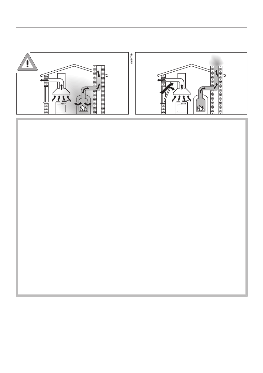
Using at the same time as other heating appliances that depend on the air from the room
Danger of toxic fumes!
Great care should be taken when using the cooker hood in the
same room or the same area of the house as another heating appliance that depends on the air from the room.
Such heating appliances draw in air from the room and duct exhaust gases out through a chimney or extraction ducting. They include gas, oil, wood and coal-fired boilers and heaters, continuous
flow or other water heaters, gas hobs and ovens.
The cooker hood draws in air from the kitchen and from neighbouring rooms. This applies to the following modes of operation:
- extraction mode,
- recirculation mode with a recirculation box installed outside the
room.
If there is insufficient air, an underpressure will occur. The heating
appliance may be starved of oxygen. This impairs combustion.
Harmful gases could be drawn from the chimney or extraction
ducting back into the room, with potentially fatal consequences.
Risk of death!
11
Page 12
Warning and Safety instructions
In order to ensure safe operation and to prevent gases given off by
the heating appliance from being drawn back into the room, when
the cooker hood and the heater are both operated simultaneously,
an underpressure in the room of 0.04mbar (4Pa) is the maximum
permissible.
Sufficient ventilation can be maintained by air inlets which cannot
be blocked, e.g. in windows, doors and outside wall vents. The
diameter of the inlet openings must enable sufficient ventilation. A
ventilation brick alone is not generally sufficient to ensure safe
ventilation.
The overall ventilation condition of the dwelling must be taken into
account. If in any doubt, the advice of a competent builder, or for
gas, a qualified gas fitter should be sought.
If the cooker hood is being operated in recirculation mode, where
the air is passed back into the room in which the extractor is installed, the above restrictions do not apply.
12
Page 13

Warning and Safety instructions
Correct use
The hob gets hot when in use and remains hot for a while after be-
ing switched off. There is a danger of burning until the residual heat
indicators go out.
Oil and fat can overheat and catch fire. Do not leave the hob unat-
tended when cooking with oil and fat. If it does ignite do not attempt
to put the flames out with water.
Disconnect the hob from the mains and use a suitable fire blanket,
saucepan lid, damp towel or similar to smother the flames.
Do not leave the hob unattended whilst it is being used. It should
be continually monitored whilst boiling and flash frying.
Open flames are a fire hazard.
Do not flambé food. When switched on, the cooker hood could draw
flames into the filter. Kitchen grease deposits could ignite.
Spray canisters, aerosols and other inflammable substances can
ignite when heated. Therefore do not store such items or substances
in a drawer under the hob. Cutlery inserts must be heat-resistant.
Do not heat an empty pan.
Do not heat up food in closed containers e.g. tins or sealed jars
on the hob, as pressure can build up in the container, causing it to
explode.
Do not cover the hob, e.g. with a hob cover, a cloth or protective
foil. The material could catch fire, shatter or melt if the hob is
switched on by mistake or if residual heat is still present.
When the appliance is switched on either deliberately or by mis-
take, or when there is residual heat present, there is the risk of any
metal items left on the hob heating up, with the danger of burning.
Depending on the material, other items left on the hob could also
melt or catch fire. Damp pan lids might adhere to the ceramic surface and be difficult to dislodge. Do not use the appliance as a resting place. Switch the cooking zones off after use.
13
Page 14

Warning and Safety instructions
You could burn yourself on the hot hob. Protect your hands with
heat-resistant pot holders or gloves when handling hot pots and
pans. Do not let them get wet or damp, as this causes heat to transfer through the material more quickly with the risk of scalding or
burning yourself.
Hot cooking vapours during cooking can cause the cooker hood
to get hot.
Do not touch the casing or the grease filters until the cooker hood
has cooled down.
When using an electrical appliance, e.g. a hand-held food blender,
near the hob, ensure that the cable of the electrical appliance cannot
come into contact with the hot hob. The insulation on the cable
could become damaged.
Grains of salt, sugar and sand (e.g. from cleaning vegetables) can
cause scratches if they get under pan bases. Make sure that the
ceramic surface is clean before placing pans on it.
Even a light object can cause damage in certain circumstances.
Do not drop anything on the ceramic surface.
Placing hot pans on the sensors and indicators could damage the
electronics underneath. Do not place hot pans on the sensors or indicators.
Do not allow solid or liquid sugar, or pieces of plastic or aluminium
foil to get onto the hob when it is hot, as they can damage the
ceramic surface when it cools down. If this should occur, switch off
the appliance and scrape off all the sugar, plastic or aluminium
residues whilst still hot, using a shielded scraper blade suitable for
use on glass. Wear oven gloves when doing this. Allow the ceramic
surface to cool down and then clean it with a suitable ceramic hob
cleaning agent.
Pans which boil dry can cause damage to the ceramic glass. Do
not leave the hob unattended whilst it is being used.
14
Page 15

Warning and Safety instructions
Only use pots and pans with smooth bases. Rough bases will
scratch the ceramic glass.
Lift pans into position on the hob. Sliding them into place can
cause scuffs and scratches.
Because induction heating works so quickly, the base of the pan
could, under certain circumstances, heat up to the temperature at
which oil or fat self-ignites within a very short time. Never leave the
hob unattended during use!
Heat oil or fat for a maximum of one minute. Never use the
Booster function to heat oil or fat.
For people fitted with a heart pacemaker: Please note that the
area immediately surrounding the hob is electromagnetically
charged. It is very unlikely to affect a pacemaker. However, if in any
doubt, consult the manufacturer of the pacemaker or your doctor.
To prevent damage to items which are susceptible to electromag-
netic fields, e.g. credit cards, digital storage devices, pocket calculators, etc, do not leave them in the immediate vicinity of the hob.
Metal utensils stored in a drawer under the hob can become hot if
the appliance is used intensively for a long time.
The hob is fitted with a cooling fan. If a drawer is fitted directly un-
derneath the hob, ensure that there is sufficient space between the
drawer and its contents and the underside of the hob in order to ensure sufficient ventilation for the hob.
If a drawer is fitted directly underneath the hob, do not store any
pointed or small items, paper, serviettes, etc. in the drawer. They
could get in through the ventilation slots or be sucked into the casing
by the fan and damage the fan or impair cooling.
Never use two pans on a cooking zone, extended zone or Power-
Flex zone at the same time.
15
Page 16

Warning and Safety instructions
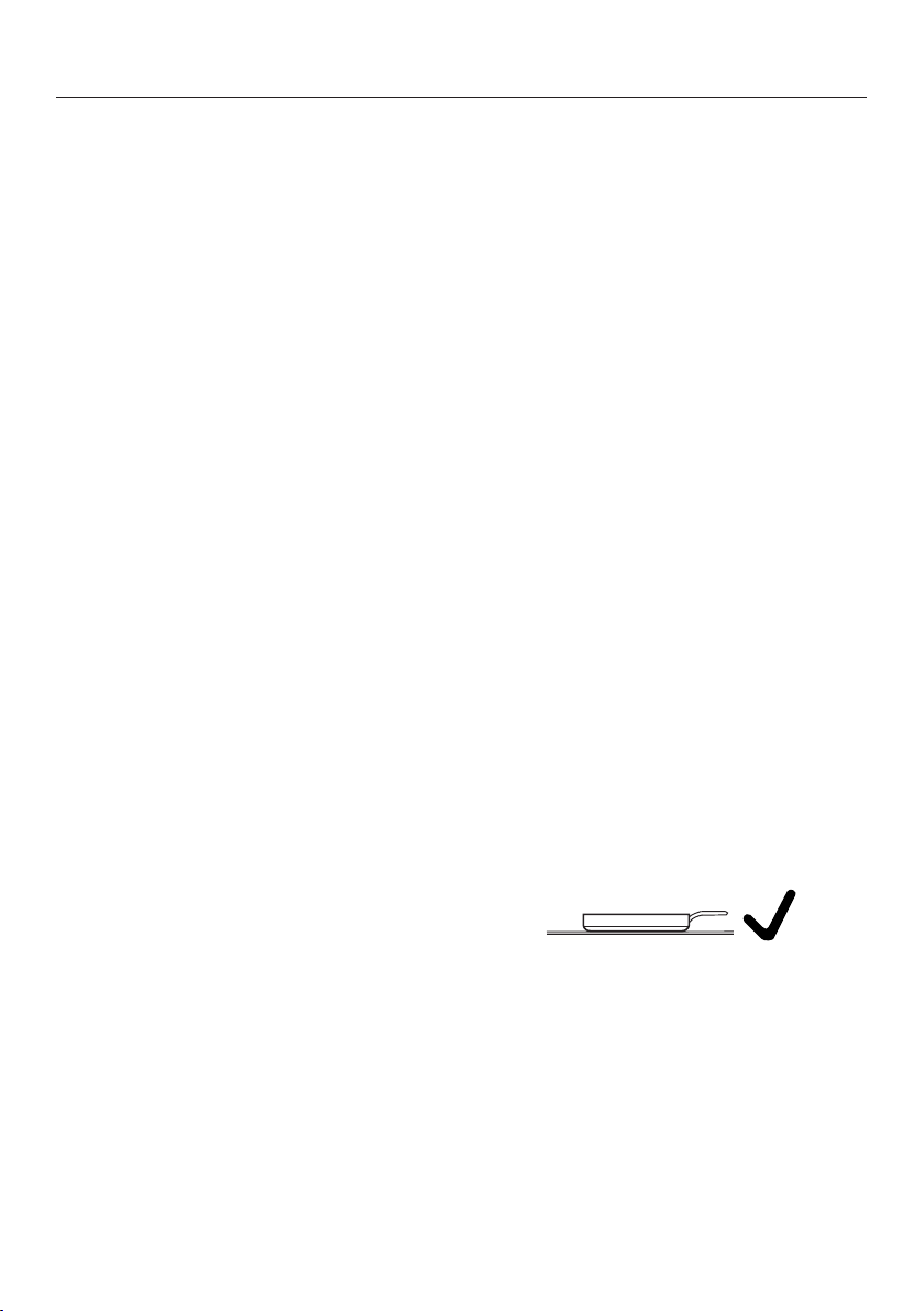
If the cookware only partially covers a cooking or extended zone,
the handle could become very hot.
Always place cookware in the middle of a cooking or extended zone!
Deposits of grease and dirt will prevent the cooker hood from
working properly.
Do not use the cooker hood without the grease filters in place. Otherwise cooking vapours will not be cleaned.
There is a risk of fire if cleaning is not carried out as described in
these operating instructions.
Do not cover the intake grille on the cooker hood when in use.
Do not place hot pans on the extraction grille of the cooker hood.
This will impair the function of the cooker hood and may damage the
extraction grille.
Liquids can damage the cooker hood if they get into it. Keep li-
quids away from the cooker hood.
Light objects can be drawn into the cooker hood and impair its
operation. Do not place any light objects (e.g. paper towels) within
close proximity of the cooker hood.
The induction generators could be damaged or even destroyed if
you use an induction adapter plate for cookware. Do not use induction adapter plates.
16
Page 17

Warning and Safety instructions
Cleaning and care
Do not use a steam cleaning appliance to clean this hob.
The steam could reach electrical components and cause a short circuit.
If the hob is built in over a pyrolytic oven, the hob should not be
used whilst the pyrolytic process is being carried out, as this could
trigger the overheating protection mechanism on the hob (see relevant section).
Accessories
Only use genuine original Miele accessories and spare parts with
this appliance. Using accessories or spare parts from other manufacturers will invalidate the warranty and Miele cannot accept liability.
Miele will guarantee to supply functional spare parts for a min-
imum of 10years and up to 15years following the discontinuation of
your hob.
17
Page 18
Caring for the environment
Disposal of the packing material
The packaging is designed to protect
the appliance from damage during
transportation. The packaging materials
used are selected from materials which
are environmentally friendly for disposal
and should be recycled.
Recycling the packaging reduces the
use of raw materials in the manufacturing process and also reduces the
amount of waste in landfill sites.
Disposing of your old appliance
Electrical and electronic appliances often contain valuable materials. They
also contain specific materials, compounds and components, which were
essential for their correct function and
safety. These could be hazardous to human health and to the environment if
disposed of with your domestic waste
or if handled incorrectly. Please do not,
therefore, dispose of your old appliance
with your household waste.
Please dispose of it at your local community waste collection / recycling
centre for electrical and electronic appliances, or contact your dealer or
Miele for advice. You are also responsible for deleting any personal data that
may be stored on the appliance being
disposed of. Please ensure that your
old appliance poses no risk to children
while being stored prior to disposal.
18
Page 19
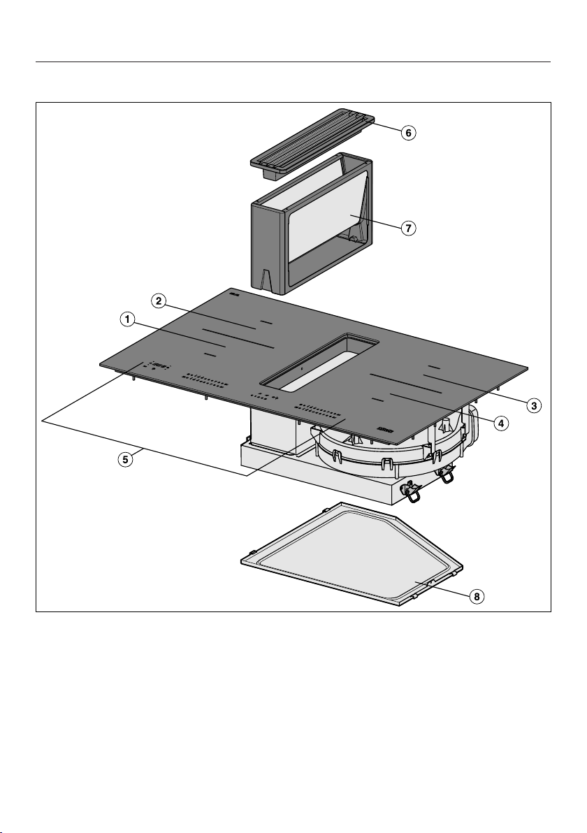
Hob
Guide to the appliance
a
PowerFlex cooking zone
b
PowerFlex cooking zone
ab
Can be combined to form a
PowerFlex cooking area
c
PowerFlex cooking zone
d
PowerFlex cooking zone
cd
Can be combined to form a
PowerFlex cooking area
e
Control elements/Indicators
f
Cover grille
g
Grease filter
h
Removable drip tray
19
Page 20
Guide to the appliance
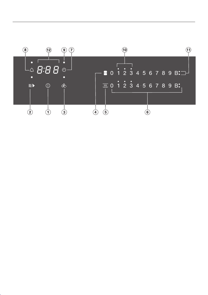
Controls / Indicators
Cooking zones/Timer
Sensor controls
a
For switching the hob on and off
b
Stop & Go
c
Wipe protection
d
For switching PowerFlex cooking zones on together/separately.
e
For activating/deactivating the keeping warm function
f
Numerical keybank
For setting power levels/minute minder and switch-off times
g
Automatic switch-off selector for cooking zones
h
Minute minder
Indicator lights
i
Automatic switch-off allocation of cooking zones
j
Residual heat
k
Booster
l
Timer display
: to
:
System lock/safety lock activated
Demonstration mode activated
20
Duration
Page 21
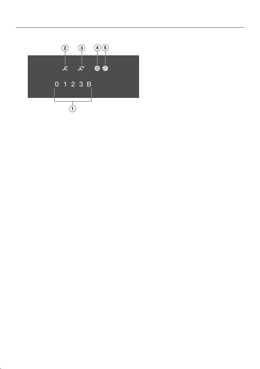
Cooker hood
a
Numerical keybank for setting the power level
b
Touch control for the 5minute run-on option
c
Touch control for the 15minute run-on option
d
Clean grease filter indicator
e
Reactivate charcoal filter indicator
Guide to the appliance
21
Page 22
Guide to the appliance
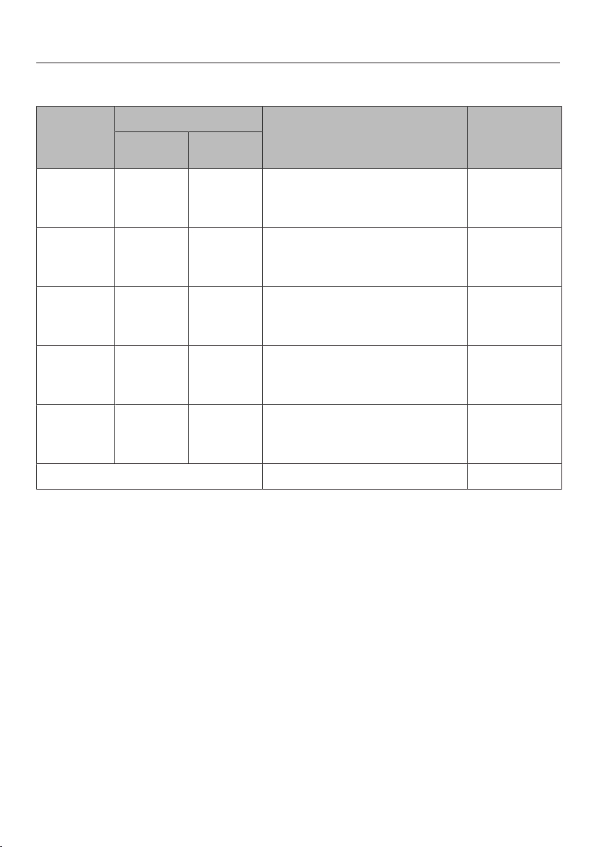
Cooking zones
Cooking
zone
Size in cm Max. rating
1
Ø
2
in watts for 230V
15–23 19x23 Normal
TwinBooster, level1
TwinBooster, level2
15–23 19x23 Normal
TwinBooster, level1
TwinBooster, level2
15–23 19x23 Normal
TwinBooster, level1
TwinBooster, level2
15–23 19x23 Normal
TwinBooster, level1
TwinBooster, level2
+
+
22–23 23x39 Normal
TwinBooster, level1
TwinBooster, level2
Total 7300
1
Cookware with a base diameter within the given range may be used.
3
2100
3000
3650
2100
3000
3650
2100
3000
3650
2100
3000
3650
3400
4800
7300
Linked
cooking
4
zone
-
2
The given range corresponds to the maximum base surface of the cookware that may be
used.
3
The wattage quoted may vary depending on the size and material of the cookware used.
4
The cooking zone is linked to this cooking zone electrically so that the rating can be increased; see “Operation – Power management”.
22
Page 23
Before using for the first time
Please stick the extra data plate for
the appliance supplied with this documentation in the space provided in
the “After sales service” section of
this booklet.
Remove any protective wrapping and
stickers.
Cleaning the hob for the first time
Before using for the first time, clean
the hob with a damp cloth only and
then wipe dry.
Switching on the hob for the first time
The metal components have a protective coating which may give off a slight
smell when heated up for the first time.
The induction coils may also give off a
slight smell for the first few hours of operation. This smell will be less noticeable with each subsequent use before
dissipating completely.
The smell and any vapours given off do
not indicate a faulty connection or appliance and they are not hazardous to
health.
Please note that the heating up time
on induction hobs is very much
shorter than on conventional hobs.
23
Page 24

Before using for the first time
Miele@home
Prerequisite: home WiFi network
Your hob is equipped with an integrated
WiFi module. The hob can be connected to your home WiFi network.
Make sure that the signal of your
WiFi network is sufficiently strong in
the place where your hob is installed.
There are a number of ways of connecting your hob to your WiFi network.
The hob requires max. 2W in networked standby.
The hob requires max. 2W in networked standby.
Availability of the WiFi connection
The WiFi connection shares a frequency
range with other appliances (including
microwave ovens and remote control
toys). This can give rise to sporadic or
even complete connection failures.
Therefore, the availability of featured
functions cannot be guaranteed.
Miele@home availability
The ability to use the Miele app depends on the availability of the
Miele@home service in your country.
The Miele@home service is not available in every country.
For information about availability,
please visit www.miele.com.
Miele App
The Miele App is available to download
free of charge from the Apple App
Store® or from the Google Play Store™.
After installing the Miele app on a mobile device, you can do the following:
- Call up information on the operating
status of your hob
- Call up information on the programme sequence of your hob
24
- Set up a Miele@home network with
other WiFi-enabled Miele appliances
Page 25
Before using for the first time
Setting up Miele@home
Connecting via the app
The Miele app can be used to connect
to your network.
Install the Miele app on your mobile
device.
To connect, you will need:
1. Your WiFi network password
2. The password for your hob
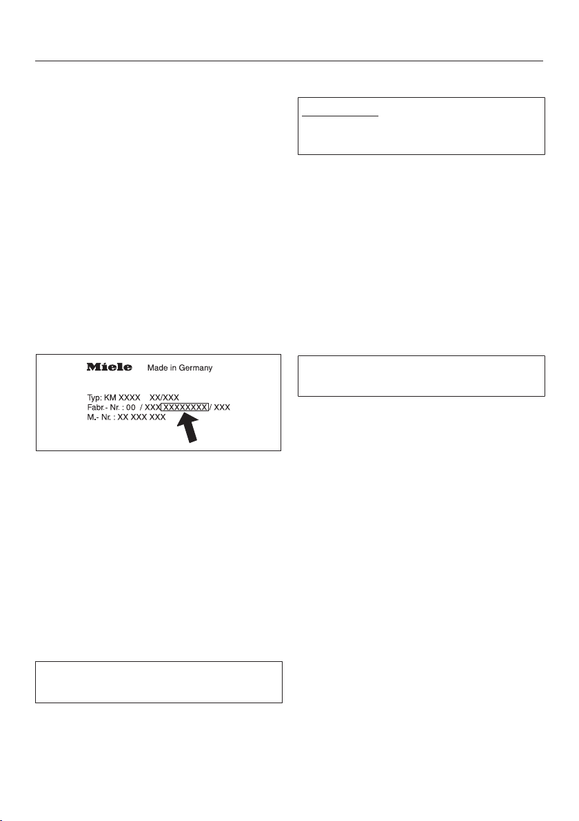
The password for your hob consists of
the last 9digits of the serial number.
This can be found on the appliance’s
data plate.
Switch the hob on.
Start the Miele app.
Touch the 0sensor control on any of
the numerical displays.
Touch the0 and 5sensor controls at
the same time for 6seconds.
The seconds can be seen counting
down in the timer display. After the time
has elapsed, the code: is displayed
in the timer display for 10seconds.
Connecting via WPS
Prerequisite: you must have a WPS
(WiFi protected setup) compatible
router.
Switch the hob on.
Touch the 0sensor control on any of
the numerical displays.
Touch the0 and 6sensor controls at
the same time for 6seconds.
The seconds can be seen counting
down in the timer display. After the time
has elapsed, a progress light appears in
the timer display during the connection
attempt (for max. 120seconds).
The WPS login is only active during
these 120seconds.
Activate the WPS function on your
WiFi router.
If the connection was successful, the
code: appears in the timer display.
If the connection could not be established, the timer display will show the
code:. You have probably not activated WPS on your router quickly
enough. Repeat the steps above.
Tip: If your WiFi router does not support
WPS, please connect via the Miele app.
You now have 10minutes to configure
the WiFi.
Follow the user navigation in the app.
25
Page 26

Before using for the first time
Cancelling the process
Touch any sensor control.
Resetting settings
Resetting is not required when replacing the router.
Switch the hob on.
Touch the 0sensor control on any of
the numerical displays.
Touch the0 and 9sensor controls at
the same time for 6seconds.
The seconds can be seen counting
down in the timer display. After the time
has elapsed, the code: is displayed
in the timer display for 10seconds.
Reset the settings if you are disposing
of your hob, selling it or putting a used
hob into operation. This is the only way
to ensure that all personal data has
been removed and the previous owner
will no longer be able to access the
hob.
26
Page 27
Induction
How it works
An induction coil is located under each
induction cooking zone. The coil creates a magnetic field that reacts directly
with the base of the pan and heats it
up. The cooking zone itself is heated up
indirectly by the heat given off by the
pan.
An induction cooking zone only works
when a pan with a magnetic base is
placed on it (see “Pans”). Induction
automatically recognises the size of the
pan.
Risk of burning due to hot items.
When the appliance is switched on
either deliberately or by mistake, or
when there is residual heat present,
there is the risk of metal items placed
on the hob heating up.
Do not use the appliance as a resting
place for anything.
After use, switch the hob off with
the sensor control.
Pans
Suitable pans
- stainless steel pans with a magnetic
base
- enamelled steel pans
- cast iron pans
Please be aware that the properties of
the pan base can affect the evenness
with which the food heats up (e.g. when
making pancakes). The base of the pan
must be able to distribute the heat
evenly. A sandwich base made of stainless steel is particularly suitable.
Unsuitable pans.
- stainless steel pans without a magnetic base
- aluminium or copper pans
- glass, ceramic or earthenware pots
and pans
Testing pans
To test whether a pan is induction-compatible, hold a magnet to the base of
the pan. If the magnet sticks, the pan is
generally suitable.
27
Page 28
Induction
No pan/unsuitable pan display
The set power level flashes in the numerical keybank for the cooking zone
- if the zone has been switched on
without a pan in place, or if the pan is
unsuitable (non-magnetic base)
- if the diameter of the base of the pan
is too small
- if the pan is taken off the cooking
zone when it is switched on
If a suitable pan is placed on the cooking zone within 3 minutes, the flashing
power level will go out and you can
continue as normal.
If no pan or an unsuitable pan is placed
on the cooking zone, the cooking zone
will switch off automatically after
3minutes.
Tips
- To make optimum use of the cooking
zones, choose cookware with a suitable base diameter (see “Overview –
Cooking zone data”). If the pan is too
small it will not be recognised.
- Position the cookware as centrally as
possible on the relevant cooking
zone/cooking area.
- Use only pots and pans with smooth
bases. Rough bases can scratch the
ceramic glass.
- Always lift cookware to move it. This
will help prevent scratching. If any
scratches do appear as a result of
cookware being pushed around, this
will not affect the function of the hob.
These scratches are normal signs of
use and are not grounds for making a
complaint.
- Please note that the maximum diameter quoted by manufacturers often
refers to the diameter of the top rim
of the pots and pans. The diameter of
the base (generally smaller) is more
important.
28
- Where possible, use pans with vertically straight sides. If a pan has angular sides, induction also acts on the
sides of the pan. The sides of the pan
may discolour or the coating may
peel off.
Page 29
Induction
Power management
The hob has a maximum total permitted
power consumption which cannot be
exceeded for safety reasons.
Cooking zones can be linked together
in pairs on the hob. This allows additional power to be transferred from one
cooking zone to another.
The previously set setting has precedence and the hob will operate with this
level.
If power is transferred from one cooking
zone to the linked cooking zone, the
power for the first cooking zone must
be reduced.
The possible values for the maximum
total permitted power consumption
and which cooking zones are linked
together can be found in “Overview –
Cooking zone data”.
If the new cooking zone requires more
power than the first cooking zone can
provide, this may result in the following
consequences for the first cooking
zone:
- The power level is reduced.
- Auto heat-up will be deactivated.
Cooking continues at the set level. If
the power is not sufficient, the power
level will be reduced again.
- The Booster function is deactivated.
- The cooking zone is switched off.
If the most recently set power level is
reduced or the Booster function is
switched off, the power level for the
linked cooking zone can be increased
again.
29
Page 30

Induction
Noises
When using an induction hob, the following noises can occur in the pan, depending on what it is made of and how
it has been constructed.
Buzzing on the higher power settings.
This will decrease or cease altogether
when the power setting is reduced.
If the pan base is made of layers of different materials (e.g. in a sandwiched
base), it might emit a crackling sound.
Whistling might occur if linked zones
(see “Operation - Booster”) are being
used at the same time, and the pans
also have bases made of layers of different materials.
You might hear a clicking sound from
the electronic switches, especially on
lower settings.
A whirring sound, when the cooling fan
comes on. This switches on to protect
the electronics when the hob is being
used intensively. The cooling fan may
continue to run after the appliance has
been switched off.
30
Page 31

How the vapour extraction works
The exhaust air drawn into the cooker
hood must not be routed into the base
unit. This will damage the unit.
Extraction mode
The air drawn in is cleaned by the
grease filter and directed outside
through a ventilation gap. The necessary accessories are available from
Miele.
Recirculation mode
The air is drawn in and cleaned by the
grease filter. The air is then directed into
the recirculation box where it is also
cleaned by a charcoal filter. The
cleaned air is then recirculated back
into the kitchen. The necessary accessories are available from Miele.
Operating hours counter
The number of hours that the cooker
hood has been used for is stored in
memory.
When the grease filter symbol or the
charcoal filter symbol , lights up, the
operating hours counters are signalling
that the filters need to be cleaned or
changed. Further information about
cleaning and changing the filters and
resetting the operating hours counter
can be found under “Cleaning and
care”.
The instruction manual supplied with
the recirculation box states that the
operating hours counter for the charcoal filter needs to be activated. This
is not necessary here.
The charcoal filter system also appears when the appliance is operated
using extraction mode.
31
Page 32

Tips on saving energy
- Use a lid whenever possible to minimise heat loss.
- Select a smaller pan when cooking
small quantities. A smaller pan uses
less energy than a larger pan with
very little in it.
- Cook with as little water as possible.
- Once food has come to the boil or
the oil in the pan is hot enough for
frying, reduce the heat to a lower setting.
- Use a pressure cooker to reduce
cooking times.
- It is important to ensure that the kitchen is well ventilated during operation. In extraction mode if there is insufficient air flow, the cooker hood
cannot operate efficiently and this
causes increased operating noise
levels.
- Always cook with the lowest possible
setting. This produces fewer cooking
vapours, so you can use a lower
power level and therefore benefit
from reduced energy consumption.
- Clean or replace the filters at regular
intervals. Heavily soiled filters reduce
performance, increase the risk of fire
and are unhygienic.
- Check the power level on the cooker
hood. A low power level is usually
sufficient. Only use the Booster setting when necessary.
- When a large volume of cooking vapours are being produced, switch to
a high power level in good time. This
is more efficient than operating the
cooker hood for longer to try to capture cooking vapours which have
already been distributed throughout
the kitchen.
- Switch the cooker hood off after
cooking.
32
Page 33

Cooking zone power levels
The cooking zones are set as standard with 9 power levels. If you wish to fine-tune
a setting, you can extend the power level range to 17power levels (see “Programming”).
Setting range
Default
setting
(9 power
levels)
Melting butter
Dissolving gelatine
Melting chocolate
Making milk puddings 2 2–2.
Heating small quantities of liquid
Cooking rice
Defrosting frozen vegetables 3 2.–3
Making porridge 3 2.–3.
Heating liquid and semi-solid food
Making omelettes and lightly frying eggs
Steaming fruit
Cooking dumplings 4 4–5.
Steaming vegetables, fish 5 5
Defrosting and reheating frozen food 5 5–5.
Gently frying eggs (without overheating the fat) 6 5.–6.
Bringing large quantities of food to the boil, e.g. casseroles
Thickening custard and sauces, e.g. Hollandaise
Gently frying meat, fish and sausages (without overheating the
fat)
Frying potato cakes, pancakes, etc 7 6.–7
Braising meat 8 8–8.
Boiling large quantities of water
Bringing to the boil
1–2 1–2.
3 3–3.
4 4–4.
6–7 6.–7
6–7 6.–7.
9 9
Extended
settings
(17 power
levels)
These settings should only be taken as a guide. The power of the induction coils will vary
depending on the size and material of the pan. For this reason it is possible that the settings
will need to be adjusted slightly to suit your pans. As you use the hob, you will get to know
which settings suit your pans best. When using new pans that you are not familiar with, set
the power level below the one specified.
33
Page 34

Operation
Using the appliance
This ceramic hob is equipped with electronic sensor controls which react to
finger contact. For safety reasons, in order to switch the appliance on, the On/
Off sensor needs to be touched for a
little longer than the other sensors.
Each time a sensor control is activated,
an audible signal sounds.
Only the printed On/Off symbol is
visible when the hob is switched off.
More sensors light up when the hob is
switched on.
Malfunction due to dirty and/or
covered sensor controls.
If the sensor controls are dirty or
covered this could cause them to fail
to react, to activate a function or
even to switch the appliance off
automatically (see “Safety features”,
“Safety switch-off”). Placing hot
pans on the sensor controls/indicators can damage the electronic unit
underneath.
Keep the sensor controls and indicators clean.
Do not place anything over the
sensor control or indicators.
Do not place hot pans over the
sensor controls or indicators.
34
Page 35

Operation
Risk of fire with overheated food.
Unattended food can overheat and
catch alight.
Do not leave the hob unattended
whilst it is being used.
Please note that the heating up time
on induction hobs is very much
shorter than on conventional hobs.
Switching on the hob
Touch the sensor.
Other sensors will light up.
If no further entry is made, the hob will
switch itself off after a few seconds for
safety reasons.
Setting the power level
Permanent pan recognition is activated as standard (see “Programming”).
When the hob is switched on and you
place a pan on one of the cooking
zones, all the sensors for that cooking
zone's numerical keybank will light up.
Switching off a cooking zone
To switch off a cooking zone, touch
the 0 sensor for that cooking zone.
To switch off the hob and all the
cooking zones, touch the sensor.
Residual heat indicator
If the cooking zone is still hot, the residual heat indicator will light up after the
zone has been switched off. Depending
on the temperature, a dot will appear
above power levels 1, 2 and 3.
The dots of the residual heat indicator
will go out one after another as the
cooking zone cools down. The last dot
only goes out when the cooking zone is
safe to touch.
Risk of burning due to hot cook-
ing zones.
The cooking zones will be hot after
use.
Do not touch the cooking zones
while the residual heat indicators are
on.
Place a pan on the cooking zone you
want to use.
Touch the appropriate number sensor
for the power level you want.
35
Page 36

Operation
Power level setting - Extended setting range
Touch the numerical keybank in
between two number sensors.
The numbers to the left and right of the
interim level light up brighter than the
others.
Example:
If you have set power level 7. the numbers 7 and 8 will be brighter than the
other numbers.
36
Page 37

Operation
PowerFlex cooking area
The PowerFlex cooking zones combine
automatically to form a PowerFlex
cooking area when you place sufficiently large items of cookware on them
(see “Guide to the appliance – Hob”).
Settings for the linked cooking area are
controlled by the numerical display of
the front or left PowerFlex cooking zone
(depending on model). The PowerFlex
cooking zones can also be switched on
and off manually:
Touch the sensor control.
Positioning cookware
Refer to the cooking zone data for your
hob model for information about cookware sizes and the corresponding positions (see “Overview – Cooking zone
data”).
PowerFlex cooking zone
PowerFlex cooking area (pot)
PowerFlex cooking area (oven dish)
37
Page 38

Operation
Auto heat-up
When Auto heat-up has been activated,
the cooking zone switches on automatically at the highest setting and then
switches to the continued cooking setting which you have previously selected. The heat-up time depends on
which continued cooking setting has
been chosen (see chart).
Activating Auto heat-up
Touch the sensor for the continued
cooking setting you want until a tone
sounds and the sensor starts to
pulsate.
During the heat-up time (see chart), the
continued cooking level set will pulsate.
With extended power levels (see “Programming”), the sensors for the power
levels in front of and after the interim
power level will pulsate if an extended
power level setting has been selected.
Altering the continued cooking setting
will deactivate Auto heat-up.
Deactivating Auto heat-up
Touch the sensor for the continued
cooking setting.
or
Set another power level.
Continued cook-
ing setting*
1 Approx. 0:15
1. Approx. 0:15
2 Approx. 0:15
2. Approx. 0:15
3 Approx. 0:25
3. Approx. 0:25
4 Approx. 0:50
4. Approx. 0:50
5 Approx. 2:00
5. Approx. 5:50
6 Approx. 5:50
6. Approx. 2:50
7 Approx. 2:50
7. Approx. 2:50
8 Approx. 2:50
8. Approx. 2:50
9 –
* The continued cooking settings with a dot
after the number are only available if the
power level range has been extended (see
“Programming”).
Heat-up time
[min : sec]
38
Page 39

Operation
Booster function
The cooking zones are equipped with a
TwinBooster.
When the Booster function is activated,
the power is boosted so that large
quantities can be heated up quickly,
e.g. when boiling water for cooking
pasta. The boost in power is active for a
maximum of 15minutes.
When the Booster function is activated, the settings for active cooking
zones may be changed, see “Induction – Power management”.
The Booster function can be used on a
maximum of 2 cooking zones or 1
PowerFlex cooking area at the same
time.
If the Booster function is switched on
when
- no power level has been selected,
the cooking zone will revert automatically to level9 at the end of the
Booster time or if the Booster function is switched off before this.
- a power level has been selected, the
cooking zone will revert automatically
to the power level selected at the end
of the Booster time or if the Booster
function is switched off before this.
Activating the TwinBooster
Level 1
Place the cookware on the cooking
zone you want to use.
Select a power level if necessary.
Touch the Bsensor control.
The indicator light for TwinBooster
level 1lights up.
Level 2
Place the cookware on the cooking
zone you want to use.
Select a power level if necessary.
Touch the Bsensor control twice.
The indicator light for TwinBooster
level 2lights up.
Deactivating TwinBooster
Touch theB sensor control re-
peatedly until the indicator lights go
out.
or
Set another power level.
39
Page 40

Operation
Keeping warm
This function is for keeping food warm
which has just been cooked and is still
hot. It is not for reheating food that
has gone cold.
The maximum duration for keeping food
warm is 2 hours.
- Only use pans for keeping food
warm. Cover the pan with a lid.
- Stir firm or viscous food (mashed
potatoes, stew) occasionally.
- Nutrients are lost when food is
cooked, and continue to diminish
when food is kept warm. The longer
food is kept warm, the greater the
loss of nutrients. Try to ensure that
food is kept warm for as short a time
as possible.
Activating/deactivating the keeping warm function
Touch the sensor for the cooking
zone you wish to use.
Keeping-warm temperatures
A keeping-warm temperature of 85°C
is set as standard. You can change the
keeping-warm temperature (see “Programming”).
Use Temperature°C
Melting chocolate 50–55
Keeping solid
food and thick liquids warm
Keeping clear
soups warm
The cooking result can be negatively
affected if food is kept warm at excessively high temperatures. Food
can change colour and even spoil.
65–75
80–90
40
Page 41

Operation
Extractor
The extractor will switch itself on automatically if a there is a pan on a cooking zone and a power level has been set
for that zone (Con@ctivity). The power
level on the extractor is set to suit to the
power level on the hob.
You can deactivate Con@ctivity temporarily.
The power level of the extractor can be
manually altered at any time. For light to
heavy cooking vapours, select from
power levels 1 to 3. For short periods of
strong vapours and cooking odours,
e.g. whilst searing meat, select the B
Booster setting.
Tip: To help release vapours effectively
with pans over 15cm high, place a
wooden spoon between the lid and the
pan.
Power level setting / Switching off
To switch the fan on touch the appro-
priate sensor for the power level you
want.
To switch the fan off touch the 0
sensor.
If the extractor is not switched off, it
will switch itself off 12hours after the
last automatic operation.
Deactivating Con@ctivity
The extractor has switched on automatically.
Touch the 0 control to deactivate
Con@ctivity.
Set the power level you want.
Con@ctivity is activated again when
you switch the hob off and back on
again.
Booster
The maximum duration for the Booster
is 10minutes.
To switch it off early, set a different
power level.
41
Page 42

Operation
Run-on time
It is advisable to run the fan for a few
minutes after cooking has finished. This
helps to neutralise any lingering vapours and odours in the air. The following two options are available:
(5minutes) and (15minutes).
The run-on duration will be carried out
using the power level set during activation. You can change the power level
during the run-on period.
Touch the or sensor to activate
the run-on period.
Touch the, or 0 sensor to deac-
tivate the run-on period.
If you switch the hob off with the
sensor, the run-on period will continue
through to the end.
42
Page 43

Timer
The hob has to be switched on if you
want to use the timer.
A duration of between 1minute(:)
and 9hours 59minutes(:) can be
set.
Durations of up to 59minutes are
shown in minutes (00:59) and durations
of more than 60minutes are shown in
hours and minutes. Durations are
entered in the order of hours, followed
by minutes in tens and then units.
Example:
59minutes = 00:59, touch: 5–9
80min = 1:20, touch: 1–2–0
After the first number has been entered,
the timer display will light up constantly.
After the second number has been
entered, the first number will move to
the left. After the third number has been
entered, the first and second numbers
will move to the left.
The timer can be used for the following
2 functions:
- For setting the minute minder
- For automatically switching a cooking
zone off.
The functions can be used at the same
time. The shortest time is always displayed and the sensor control
(minute minder) or the indicator light of
the cooking zone for automatic switchoff pulsates.
Touch the orsensor control if you
want to show the times left counting
down in the background. If a switch-off
time has been programmed for several
cooking zones, touch the sensor
control repeatedly until the indicator
light for the required cooking zone
pulsates.
Minute minder
The minute minder is set using the numerical keybank for the left or front left
cooking zone (depending on model).
Setting the minute minder
Touch the sensor control.
The timer display starts flashing.
Set the required time.
Changing the minute minder duration
Touch the sensor control.
Set the required time.
Deleting the minute minder duration
Touch the sensor control re-
peatedly until: appears in the
timer display.
43
Page 44

Timer
Switching off a cooking zone automatically
You can set a time after which a cooking zone will switch off automatically.
This function can be used for all cooking zones at the same time.
The switch-off time is set on the numerical display for each cooking zone
you want to switch off automatically.
If the time programmed is longer than
the maximum operational time allowed, the safety switch-off will switch
off the cooking zone after the maximum permitted safety time has
elapsed (see “Safety features – Safety
switch-off”).
Select a power level for the cooking
zone you require.
Touch the sensor control.
The indicator light will begin to flash.
Set the required duration.
Changing the switch-off time
Touch the sensor control re-
peatedly until the indicator light for
the cooking zone you require flashes.
Set the required duration.
Deleting the switch-off time
Touch the sensor control re-
peatedly until the indicator light for
the cooking zone you require flashes.
Touch the 0 sensor control on the nu-
merical display.
If you want to set another cooking
zone to switch off automatically, follow the same steps as described
above.
If more than one switch off time is programmed, the shortest time left will be
displayed, and the corresponding indicator light will flash. All the other indicator lights will light up constantly.
If you want to show the time left for
another zone which is counting down
in the background, touch the
sensor control repeatedly until the
indicator light for the zone you require
flashes.
44
Page 45

Additional functions
Stop&Go
When Stop & Go is activated, the power
of all cooking zones in use is reduced to
power level1. The power level of the
extractor is not reduced. Depending on
the power level set for the hob, it may
even increase.
The cooking zone power levels and the
timer settings cannot be altered, the
hob can only be switched off. The
minute minder, switch-off, booster and
AutoBoost times continue to run.
When Stop&Go is deactivated, the
cooking zones will operate at the power
level previously selected.
If the function is not deactivated within
1 hour, the hob will switch off.
Activating/Deactivating
Touch the sensor control.
Use this function if there is a danger of
food boiling over.
Recall
If the hob is switched off in error during
operation, this function can be used to
reset all settings. For this to work, the
hob must be switched on again within
10seconds of being switched off.
Switch the hob on again.
The previously set power level flashes.
Touch one of the flashing power
levels immediately.
All the cooking zones and the timer will
continue to operate using the settings
selected previously.
45
Page 46

Additional functions
Wipe protection
The hob sensors can be locked for
20s in order, for example, to remove
soiling. The is not locked.
Activating
Touch the sensor.
The time will count down in the timer
display.
Deactivating
Touch the sensor until the timer
display goes out.
Demonstration mode
This function enables the hob to be
demonstrated in showrooms without
heating up.
Activating / Deactivating
Switch the hob on.
Touch the0 sensor control on any of
the numerical keybanks.
Then touch the0 and 2 sensors at
the same time for 6seconds.
In the timer display, flashes alternately with (demonstration mode activated) or (demonstration mode deactivated) for a few seconds.
Displaying hob data
The model number and software version of the hob can be displayed. There
must not be any pots or pans on the
hob.
Model designation
Switch the hob on.
Touch the0 sensor control on any of
the numerical keybanks.
Then touch the 0 and 4 sensor con-
trols at the same time.
The timer display shows 2 numbers
flashing alternately:
Example: flashing alternately with
= KM1234
Software version
Switch the hob on.
Touch the0 sensor control on any of
the numerical keybanks.
Then touch the 0 and 3 sensor con-
trols at the same time.
Numbers appear in the timer display:
Example: : = Software version 2.00
46
Page 47

Safety features
System lock / Safety lock
The lock function is deactivated if
there is a break in the mains supply.
Your hob is equipped with a system
lock and a safety lock to prevent the
hob and the cooking zones being
switched on or any settings being
altered.
The system lock is activated when the
hob is switched off. If the system lock is
activated, the hob cannot be switched
on and the timer cannot be used. A set
minute minder time continues to count
down. The hob is programmed so that
the system lock must be activated
manually. It can be programmed to be
activated automatically 5minutes after
the hob has been switched off if it is not
manually locked first (see “Programming”).
The safety lock is activated when the
hob is switched on. When the safety
lock is activated, the hob can be operated only under certain conditions:
- The cooking zones, the cooker hood
and the hob can only be switched off.
- A set minute minder time can be
modified.
If an unavailable sensor control is
touched whilst the system lock or
safety lock is activated will appear
in the timer display for a few seconds
and a tone will sound.
Activating the system lock
Touch the sensor for 6seconds.
The seconds can be seen counting
down in the timer display. When this
time has elapsed will appear in the
timer display. The system lock has been
activated.
Deactivating the system lock
Touch the sensor for 6seconds.
will appear briefly in the timer dis-
play and then the seconds will be seen
counting down. The system lock is deactivated once the time has elapsed.
47
Page 48

Safety features
Activating the safety lock
Touch and hold the and
sensors at the same time for
6seconds.
The seconds can be seen counting
down in the timer display. When this
time has elapsed will appear in the
timer display. The safety lock is activated.
Deactivating the safety lock
Touch and hold the and
sensors at the same time for
6seconds.
will appear briefly in the timer display and then the seconds will be seen
counting down. Once the time has
elapsed, the lock function is deactivated.
48
Page 49

Safety features
Safety switch-off
Sensor controls are covered
Your hob will turn off automatically if
one or several of the sensors remain
covered for longer than 10 seconds, for
example, by finger contact, food boiling
over or by an object such as an oven
glove or tea towel. flashes briefly
above the sensor control and a tone
will sound.
will go out once you have removed
the object and/or cleaned the hob and
the hob will be ready to use again.
Excessive operating time
The safety switch-off mechanism is
triggered automatically if a cooking
zone is heated for an unusually long
period of time. This time depends on
the power level selected. If it has been
exceeded, the cooking zone switches
off and the residual heat indicator appears. If you switch the cooking zone
on and off again, it is ready for operation again.
Power level* Maximum operating time
[h:min]
Safety setting
0** 1 2
1 10:00 8:00 5:00
1. 10:00 7:00 4:00
2/2. 5:00 4:00 3:00
3/3. 5:00 3:30 2:00
4/4. 4:00 2:00 1:30
5/5. 4:00 1:30 1:00
6/6. 4:00 1:00 0:30
7/7. 4:00 0:42 0:24
8 4:00 0:30 0:20
8. 4:00 0:30 0:18
9 1:00 0:24 0:10
* The power levels with a dot after the number are only available if the power level
range has been extended (see “Setting
range”).
** Factory default setting
The hob is programmed to safety setting 0 at the factory. If necessary, a
higher safety setting with a shorter
maximum operating time can be set
(see chart).
49
Page 50

Safety features
Overheating protection
All the induction coils and cooling elements for the electronics are fitted with
an overheating protection mechanism.
Before the induction coils and/or cooling elements get too hot, the overheating protection mechanism cuts in in one
of the following ways:
Induction coils
- Any Booster function in operation will
be switched off.
- The set power level will be reduced.
- The cooking zone turns off automatically. will flash alternately
within the timer display.
You can use the cooking zone again as
usual when the fault code has gone out.
Cooling elements
- Any Booster function in operation will
be switched off.
- The set power level will be reduced.
The overheating protection may be activated under the following circumstances:
- The pan being heated is empty.
- Fat or oil is being heated on a high
power level.
- There is insufficient ventilation to the
underside of the hob.
- A hot cooking zone is switched on
after an interruption to the power
supply.
If, despite removing the cause, the
overheating protection mechanism triggers again, contact the Customer Service Department.
- The cooking zones switch off automatically.
The affected cooking zones can only be
used again as usual once the cooling
element has cooled down to a safe
level.
50
Page 51

Programming
You can adapt the programming of the
hob to your personal needs. Several
settings can be altered in succession.
After accessing programming mode,
the symbol appears and will appear in the timer display. After a few
seconds : (Programme 01) will flash
alternately with : (Code) in the timer
display.
Change programming
Accessing programming mode
The sensor is located approx.
1cm (index finger width) to the left of
the sensor.
With the hob switched off, touch
the and sensors at the same
time until the symbol and appear in the timer display.
Setting a programme
For a two digit programme number
you need to first set the tens position.
To save the settings
While the programme is showing in
the display (e.g. :) touch the
sensor until the indicators go out.
To avoid saving the settings
While the code is showing in the dis-
play (e.g. :) touch the sensor
until the indicators go out.
Whilst the programme is visible in the
display (e.g. :), touch
thesensor repeatedly until the
number for the programme you want
appears in the display or touch the
appropriate number on the numerical
keybank.
Setting the code
Whilst the code is visible in the dis-
play (e.g. :), touch thesensor
repeatedly until the number for the
code you want appears in the display
or touch the appropriate number on
the numerical keybank.
51
Page 52

Programming
Programme
P:01
P:03
P:04
P:06
P:07
P:08
Demo mode
Factory default setting
Number of cooking zone power
levels
Audible tone when a sensor
control is touched
Timer buzzer
System lock
1
Code
C:00
C:01
C:00
C:01
C:00
C:01
C:00
C:01
C:02
C:03
C:00
C:01
C:02
C:03
C:00
C:01
2
Settings
Demo mode off
Demo mode on
Do not restore factory default settings
Restore factory default settings
9 power levels + Booster
17 power levels + Booster
5
Off
Quiet
Medium
Loud
Off
Quiet
Medium
Loud
System lock can only be activated
manually
System lock activated automatically
3
4
52
Page 53

Programming
Programme
P:09
P:10
P:12
P:15
Maximum operating time
WiFi registration
Sensor controls reaction speed
Permanent pan recognition
1
Code
C:00
C:01
C:02
C:00
C:01
C:02
C:03
C:04
C:05
C:00
C:01
C:02
C:00
C:01
2
Settings
Safety setting 0
Safety setting 1
Safety setting 2
Not active/deactivated
Active but not configured
Active and configured (cannot be selected; displays whether connection
was successful)
Connection possible via WPS push
button
WiFi reset to default (C:00)
Direct WiFi connection of hob and
external cooker hood without Miele
app (Con@ctivity3.0)
Slow
Normal
Fast
Not active
Active
53
Page 54

Programming
Programme
P:25
1
Unlisted programmes are not assigned.
2
The factory-set code is shown in bold.
3
After the hob has been switched on appears in the timer display for a few seconds.
4
In the text and charts, the extended power levels are shown with a dot after the number
1
Keeping warm temperature
Code
C:00
C:01
C:02
C:03
C:04
C:05
C:06
C:07
C:08
2
Settings
50°C
55°C
60°C
65°C
70°C
75°C
80°C
85°C
90°C
for better understanding.
5
The audible tone for the On/Off sensor control cannot be switched off.
54
Page 55

Note for test institutes
Test food acc. to EN60350-2
9 power levels are programmed at the factory.
For testing in accordance with the above standard, programme the hob to the extended power level setting.
Test food
Heating oil up 150 No – 1–2
Pancakes 180
Frying deep frozen chips According to the standard No 9 9
Pan base (mm)
(Sandwich base)
Lid
No 9 5.–7.
Power level
Pre-heat Cooking
55
Page 56

Cleaning and care
Risk of burning due to hot cook-
ing zones.
The cooking zones will be hot after
use.
Switch the hob off.
Allow the cooking zones to cool
down before cleaning the hob.
Risk of damage due to moisture
ingress.
The steam from a steam cleaning ap-
pliance could reach live electrical
components and cause a short circuit.
Do not use a steam cleaner to clean
the hob.
All surfaces could be discoloured or
damaged if unsuitable cleaning
agents are used. All surfaces are
susceptible to scratching.
Remove all cleaning agent residues
immediately.
Never use abrasive sponges or
cleaning agents.
Clean the hob after every use.
Dry the hob thoroughly after cleaning
with water to avoid limescale residue.
Unsuitable cleaning agents
To avoid damaging the surfaces of the
appliance, do not use:
- washing-up liquid
- cleaning agents containing soda, alkalines, ammonia, acids or chlorides
- cleaning agents containing descaling
agents
- stain and rust removers
- abrasive cleaning agents, e.g.
powder cleaners and cream cleaners
- solvent-based cleaning agents
- dishwasher cleaner
- oven sprays
- glass cleaning agents
- hard, abrasive brushes or sponges
(e.g. pot scourers) or sponges which
have been previously used and still
contain abrasive cleaning agents
56
- melamine eraser blocks
Page 57

Cleaning and care
Cleaning the ceramic surface
Risk of damage by pointed ob-
jects.
The seal between the hob and the
worktop could suffer damage.
The seal between the ceramic surface and the frame could suffer damage.
Do not use pointed objects for cleaning.
Not all soiling and residues can be
removed using a solution of washing-up liquid. An invisible film can
develop that can lead to discolouration of the glass ceramic surface.
This discolouration cannot be removed.
Clean the ceramic surface regularly
with a proprietary ceramic glass
cleaning agent.
Remove any coarse soiling with a
damp cloth and more stubborn soiling with a shielded scraper blade
suitable for use on glass.
Then clean the ceramic glass surface
with the Miele ceramic and stainless
steel hob cleaner (see “optional accessories”) or with a proprietary
ceramic glass cleaner applied with
kitchen paper or a clean cloth. Do not
apply the cleaner while the hob is still
hot, as this can result in marking.
Please follow the cleaning agent
manufacturer's instructions.
Residues can burn onto the hob the
next time it is used and cause damage
to the glass ceramic surface. Ensure
that all cleaning agent residues are removed.
Spots caused by limescale, water
and aluminium residues (spots with a
metallic appearance) can be removed
using Miele's ceramic and stainless
steel hob cleaner.
Risk of burning due to hot cook-
ing zones.
The cooking zones are hot during
use.
Wear oven gloves when removing
residues of sugar, plastic or aluminium foil from a hot ceramic surface with a shielded scraper blade.
Should any sugar, plastic or alu-
minium foil spill or fall onto the hot
ceramic surface while it is in use,
switch off the cooking zone.
Then carefully scrape off these
residues immediately whilst they are
still hot, using a scraper blade suitable for use on glass.
Afterwards, clean the ceramic surface
in its cooled state, as described
above.
Finally wipe the glass ceramic surface
with a damp cloth and polish with a
soft, dry cloth.
57
Page 58

Cleaning and care
Grease filter/extraction grille
The extraction grille and the reusable
metal grease filter in the vapour extraction fan collect solid matter from kitchen vapours (grease, dust, etc.) and
therefore prevent soiling of the
downdraft extractor. Accumulated
grease solidifies over a longer period of
time and makes cleaning more difficult.
The grease filter should therefore be
cleaned at least every 3–4weeks.
Risk of fire due to soiled grease
filter.
Grease collected in the grease filter
can ignite.
Clean the grease filter regularly.
Removing the extraction grille
Risk of damage to the extraction
grille.
Pull the extraction grille vertically out
of the top of the KMDA.
Removing the grease filter
Lift up the extraction grille.
Remove the grease filter carefully. Do
not let the grease filter tip over.
Pour out any liquid which has collec-
ted at the bottom of the grease filter.
Fitting the grease filter
The grease filter has a symbol on the
front. The arrow on this points to the
right or left.
Insert the grease filter so that the ar-
row is pointing to the opening inside
the casing.
Take hold of the extraction grille in the
centre of the bars.
Pull the extraction grille up vertically.
58
Page 59

Cleaning and care
Cleaning the extraction grille and the grease filter by hand
Clean the extraction grille and the
grease filter with a soft nylon brush in
a mild solution of hot water and a
little washing-up liquid. Do not use
concentrated washing-up liquid.
Cleaning the extraction grille and the grease filter in the dishwasher
Place the extraction grille upright in
the lower basket.
Place the grease filter with its base
facing upwards in the lower basket.
Ensure the spray arm is not obstructed.
Use a standard household dish-
washer detergent.
Select a dishwasher programme with
a maximum wash temperature of:
- 55°C for the extraction grille
- 65°C for the grease filter
Depending on the detergent used,
cleaning the grease filter in a dishwasher can cause permanent discolouration to the internal surfaces of the
filter. However, this will not affect the
functioning of the grease filter in any
way.
Cooker hood drip tray
Clean the drip tray if liquid from food
being spilled or boiling over has got into
the cooker hood.
Remove and clean the grease filter as
described in “Cleaning and care”
–“Grease filter/Extraction grille”.
Hold the drip tray securely and open
the 4 catches (2 on the right and 2 on
the left). Carefully remove the tray
from the casing, making sure it is
kept horizontal.
Pour out the liquid.
Clean and dry the drip tray.
Also clean and dry accessible areas
inside of the cooker hood.
Fasten the drip tray back onto the
casing.
Replace the grease filter and replace
the extraction grille.
Internal surfaces of the cooker hood
Whilst the grease filter is removed re-
move any grease deposits from all
accessible areas of the housing Doing so will prevent a fire hazard.
59
Page 60

Cleaning and care
Resetting the grease filter operating hours counter
After cleaning the grease filter, the operating hours counter needs to be reset.
Touch the sensor for 3seconds.
The sensor will go out.
Reactivating charcoal filter
The charcoal filter needs to be reactivated after 120operating hours. The
sensor will light up.
Reactivate the charcoal filter as de-
scribed in the operating instructions
supplied with the recirculation box.
Resetting the charcoal filter operating hours counter
Touch the sensor for 3seconds.
The sensor will go out.
60
Page 61
Problem solving guide
Many malfunctions and faults that can occur in daily operation can be easily
remedied. Time and money will be saved because a service call will not be
needed.
The following guide may help you to find the reason for a malfunction or a fault,
and to correct it.
Problem Cause and remedy
The hob or cooking
zones will not switch
on.
A smell and vapours are
given off when the new
appliance is being used.
The power level selected is flashing.
After the hob has been
switched on, or after
touching a sensor,
appears in the timer
display for a few
seconds.
There is no power to the hob.
Check whether the mains fuse has tripped. Con-
tact an electrician or Miele Service (for the minimum fuse rating, see data plate).
There may be a technical fault.
Disconnect the appliance from the mains electri-
city supply for approx. 1 minute by
– tripping the relevant mains fuse or screwing the
fuse out completely, or
– switching off at the residual current device.
If, after resetting the trip switch in the mains fuse
box or the residual current current device, the appliance will still not turn on, contact a qualified
electrician or Miele Service.
The metal components have a protective coating.
When the appliance is used for the first time, this
causes a smell and possibly also vapour. The material from which the induction coils are made also gives
off a smell in the first few hours of operation. With
each subsequent use, the odour is reduced until it
disappears completely. The smell and any vapours
given off do not indicate a faulty connection or appliance and they are not hazardous to health.
There is no pan on the cooking zone, or the pan is
unsuitable.
Use suitable pans (see “Induction - Pans”).
The system lock or safety lock is activated.
Deactivate the system lock or safety lock (see
“System lock / Safety lock”).
61
Page 62

Problem solving guide
Problem Cause and remedy
The hob has switched
off automatically. When
the element is switched
back on, appears
above the On/Off
sensor control.
After the hob has been
switched on, appears
briefly in the timer display. The cooking zones
do not heat up.
A cooking zone
switches off automatically.
A cooking zone or the
whole hob switches off
automatically.
The Booster has deactivated early automatically.
The cooking zone is not
working in the usual
way on the power setting selected.
Power level 9 is automatically reduced if you
select power level 9 on
two linked cooking
zones at the same time.
The food in the pan
does not heat up when
the Auto heat-up function is switched on.
One or more of the sensor controls are covered, e.g.
by finger contact, food boiling over or an object.
Clean off any dirt and/or remove the object (see
“Safety features” – “Safety switch-off”).
The hob is in demonstration mode.
Touch the 0sensor control on any of the numerical
displays.
Then touch the and sensor controls at the
same time until flashes alternately with in
the timer display.
It has been operated for too long.
You can use the cooking zone again by switching
it back on (see “Safety switch-off”).
The overheating protection mechanism has been activated.
See “Safety features”.
The overheating protection mechanism has been activated.
See “Safety features”.
The overheating protection mechanism has been activated.
See “Safety features”.
Operating both zones at power level 9 would exceed
the permitted maximum power for the two zones.
Use a different cooking zone.
A large amount of food is being heated up.
Start cooking at the highest power level and then
turn down to a lower one manually later on.
The pan is not conducting heat properly.
Use a different pot or pan which conducts heat
properly.
62
Page 63

Problem Cause and remedy
An operating noise can
be heard after the appliance has been switched
off.
is flashing alternately with in the timer
display and the buzzer
is sounding.
“1” and a number,
e.g.1–0, is flashing alternately with a 3-digit
number in the timer display.
flashes alternately
with numbers in the
timer display.
The cooling fan runs until the hob has cooled down
and then switches off automatically.
The hob is incorrectly connected.
Disconnect the hob from the mains electricity sup-
ply.
Contact the Customer Service Department. The
hob must be connected to the mains according to
the wiring diagram.
Cooking zone fault
Disconnect the power supply to the hob for ap-
prox. 1minute.
If the problem persists after power has been re-
stored, please contact the Customer Service Department.
The overheating protection mechanism has been activated.
See “Safety features – Overheating protection”.
, or
The fan is blocked or defective.
Make sure it has not been blocked by an object.
Remove the obstruction.
If this fault code continues to appear in the dis-
play, contact the Customer Service Department.
and other numbers
There is a fault in the electronic module.
Disconnect the power supply to the hob for ap-
prox. 1minute.
If the problem persists after power has been re-
stored, please contact the Customer Service Department.
Problem solving guide
63
Page 64

Problem solving guide
Problem Cause and remedy
Liquid has got into the
cooker hood.
Extraction performance
has decreased. Extraction noise has increased.
The sensor control is
lit up.
The sensor control is
lit up.
Due to boiling over or spillage, liquid has made its
way through the extraction grille into the cooker
hood.
The base of the grease filter can hold approx. 250ml
of liquid. The drip tray underneath the housing can
hold a further 250ml of liquid.
Switch the cooker hood off.
Clean the grease filter, the drip tray and the inside
of the housing (see “Cleaning and care”).
Objects (e.g. a cloth) have been drawn into the
cooker hood.
Switch the cooker hood off.
Remove the grease filter (see “Cleaning and care”).
Remove any objects from the grease filter.
The charcoal filter needs to be reactivated.
If the cooker hood is being operated in Recircula-
tion mode, reactivate the charcoal filter as de-
scribed in the operating and installation instructions supplied with the recirculation box. Reset the
operating hours counter (see “Cleaning and care”
– “Resetting the charcoal filter operating hours
counter” in these operating and installation instructions).
If the cooker hood is being operated in Extraction
mode, reset the operating hours counter (see
“Cleaning and care” – “Resetting the grease filter
operating hours counter” in these operating and
installation instructions).
The grease filter must be cleaned.
Clean the grease filter as described in “Cleaning
and care” –“Grease filter/Extraction grille”.
64
Page 65

Optional accessories
Miele offer a comprehensive range of
useful accessories as well as cleaning
and conditioning products for your
Miele appliances.
These products can be ordered through
the Miele Webshop.
They can also be ordered from Miele
(see end of this booklet for contact details) or from your Miele dealer.
Cookware
Miele offers a wide range of cookware.
These have all been optimised for Miele
appliances in terms of functionality and
dimensions. Detailed information is
provided on the Miele website.
Cleaning and care products
Ceramic and stainless steel hob
cleaner 250ml
Removes heavy soiling, limescale deposits and aluminium residues
Microfibre cloth
Removes finger marks and light soiling
65
Page 66

*INSTALLATION*
Installation
Safety instructions for installation
Damage risk from incorrect installation.
Incorrect installation can cause damage to the hob.
The hob must only be installed by a qualified person.
Risk of electric shock.
Incorrect connection to the mains supply may result in an electric shock.
The hob must be connected to the electrical supply by a qualified person only.
Damage from falling objects.
Take care not to damage the hob when fitting wall units or a cooker hood above
it.
Fit the wall units and the cooker hood before the hob.
The veneer or laminate coatings of worktops (or adjacent kitchen
units) must be treated with 100°C heat-resistant adhesive which will
not dissolve or distort. Any backmoulds must be of heat-resistant
material.
The hob must not be installed over a fridge, fridge-freezer, freezer,
dishwasher, washing machine, washer-dryer or tumble dryer.
A gas hob must not be installed next to this hob.
This hob must not be installed above ovens or cookers unless
these have a built-in cooling down fan.
After installation, ensure that nothing can come into contact with
the connection cable and that it is without hindrance.
The electrical cable may not come into contact with any moving
kitchen component (e.g. a drawer) or be subject to mechanical obstruction which could damage it.
Observe carefully the safety clearances listed on the following
pages.
66
Page 67

*INSTALLATION*
Installation
Exhaust ducting must be of non-inflammable material. Suitable
material is available from Miele specialist dealers or the Miele Spares
Dept.
The appliance must not be connected to a chimney or flue which
is in use. Neither should it be connected to ducting which ventilates
rooms with fireplaces.
If exhaust air is to be extracted into a chimney or ventilation duct
no longer used for other purposes, seek professional advice.
The extracted air drawn into the cooker hood must not be routed
into the base unit, as this will damage the cabinet. The extracted air
must be routed outside through ducting (extraction mode) or back
into the room through the recirculation box (recirculation mode).
67
Page 68

*INSTALLATION*
Installation
Safety distances
Safety distance above the hob
The safety distance specified by the
manufacturer of the cooker hood must
be maintained between the hob and the
cooker hood above it.
If combustible objects are installed
above the hob (e.g., cabinets, utensil
rail, etc.), a minimum safety distance of
600mm must be maintained.
When two or more appliances which
have different safety distances are
installed together below a cooker
hood, you should observe the
greatest specified safety distance.
68
Page 69

*INSTALLATION*
Safety distances to the sides and back of the hob
It is advisable to install the hob with
plenty of space either side of it.
The minimum distance shown below
must be maintained between the back
of the hob and a tall unit or wall.
Installation
The minimum distance , shown
below must be maintained between a
tall unit or a wall to the left or right of
the hob with a minimum distance of
300mm on the opposite side.
Minimum distance between the back
of the worktop cut-out and the rear
edge of the worktop:
50mm
Minimum distance between the
worktop cut-out and a wall or tall unit to
the right of it:
50mm.
Minimum distance between the
worktop cut-out and a wall or tall unit to
the left of it:
50mm.
Not allowed
Highly recommended
Not recommended
Not recommended
69
Page 70

*INSTALLATION*
Installation
Safety distance when installing the appliance near a wall with additional niche cladding
A minimum safety distance must be maintained between the worktop cut-out and
any niche cladding to protect it from heat damage.
If the niche cladding is made from a combustible material (e.g. wood) a minimum
safety distance of 50 mm must be maintained between the cut-out and the
cladding.
If the niche cladding is made from a non-combustible material (e.g. metal, natural
stone, ceramic tiles) the minimum safety distance between the cut-out and the
cladding will be 50 mm less the thickness of the cladding.
Example: 15 mm niche cladding
50mm - 15mm = minimum safety distance of 35mm
Flush-fitted hobs Hob with frame or bevelled edge
a
Masonry
b
Niche cladding dimension x = thickness of the niche cladding material
c
Worktop
d
Worktop cut-out
e
Minimum distance to
combustible materials 50mm
non-combustible materials 50mm - dimension x
70
Page 71

*INSTALLATION*
Installation
Installation notes
All dimensions are given in mm.
Surface-mounted installation
Seal between the hob and the worktop
Damage caused by incorrect in-
stallation.
Using sealant under the hob could
result in damage to the hob and the
worktop if the hob ever needs to be
removed for servicing.
Do not use sealant between the hob
and the worktop.
The sealing strip under the edge of
the hob provides a sufficient seal for
the worktop.
Tiled worktops
Grout lines and the hatched area underneath the hob frame must be
smooth and even. If they are not the
hob will not sit flush with the worktop
and the sealing strip underneath the
hob will not provide a good seal
between the hob and the worktop.
71
Page 72

*INSTALLATION*
Installation
Flush-fit installation
Flush-fit installation is only possible in
natural stone (granite, marble), solid
wood and tiled worktops. Certain
models are suitable for building into
glass worktops – please see the relevant label on the hob. When using a
worktop made from any other material, please check first with the worktop
manufacturer that it is suitable for installing a flush-fit hob.
The internal width of the base unit underneath the appliance must be at
least as wide as the inner worktop cutout (see “Installation – Building-in dimensions – flush fit”), so that the hob
is easily accessible from underneath
after installation and the bottom half of
the casing can be removed for maintenance. If the underside of the hob is
not freely accessible after installation,
any sealant used to plug the gaps
around the appliance must be removed to enable the hob to be lifted
out of the cut-out should this be necessary.
Natural stone worktops
The hob is set directly in the cut-out.
Solid wood worktops, tiled worktops,
glass worktops
The hob is secured inside the cut-out
with wooden battens. The battens must
be provided on site, and are not supplied with the appliance.
Minimum plinth height
The minimum plinth height is 100mm.
Housing unit back panel
The extraction ducting is laid behind the
housing unit back panel. The back
panel must be removable for maintenance purposes.
Drip tray
The hob must be installed such that the
drip tray is easily accessible as it needs
to be removed for cleaning.
Sealing strip
Dismantling the hob for service purposes may damage the sealing strip
underneath the edge of the hob.
Always replace the sealing strip before reinstalling the hob.
72
Page 73

*INSTALLATION*
Installation examples
Recirculation mode
Installation
Extraction mode
73
Page 74

*INSTALLATION*
Installation
Installation dimensions – Surface-mounted
KMDA7633FR, KMDA7634FR
a
Front
b
Removable drip tray
c
Mains connection box with mains
connection cable, L = 1440mm
d
Air duct connection – at the back
(ex-works)
e
Air duct connection – on the right
(conversion required)
f
Air duct connection – on the left
(conversion required)
74
Page 75

*INSTALLATION*
Installation
KMDA7633FL, KMDA7634FL
a
Front
b
Removable drip tray
c
Mains connection box with mains
connection cable, L = 1440mm
d
Air duct connection – at the back
(ex-works)
e
Air duct connection – on the right
(conversion required)
f
Air duct connection – on the left
(conversion required)
75
Page 76

*INSTALLATION*
Installation
Worktop depth 600mm
KMDA7633FR, KMDA7634FR
a
Housing unit back panel
The housing unit back panel must be
removable for service work. The
housing unit wall and an adjoining
room wall or a piece of furniture
must be at least 110mm apart to
ensure sufficient room for the ducting.
b
Drip tray
After installation the removable drip
tray must be accessible from below.
KMDA7633FL, KMDA7634FL
a
Housing unit back panel
The housing unit back panel must be
removable for service work. The
housing unit wall and an adjoining
room wall or a piece of furniture
must be at least 110mm apart to
ensure sufficient room for the ducting.
b
Drip tray
After installation the removable drip
tray must be accessible from below.
76
Page 77

*INSTALLATION*
Extraction to the rear (standard)
Extraction to the right
Installation
Extraction to the left
77
Page 78

*INSTALLATION*
Installation
Worktop depth greater than 600mm
KMDA7633FR, KMDA7634FR
a
Housing unit back panel
The housing unit back panel must be
removable for service work. The
housing unit wall and an adjoining
room wall or a piece of furniture
must be at least 110mm apart to
ensure sufficient room for the ducting.
b
Variable length of interim piece
c
Drip tray
After installation the removable drip
tray must be accessible from below.
x= Dimension by which the worktop is
deeper than 600mm.
KMDA7633FL, KMDA7634FL
a
Housing unit back panel
The housing unit back panel must be
removable for service work. The
housing unit wall and an adjoining
room wall or a piece of furniture
must be at least 110mm apart to
ensure sufficient room for the ducting.
b
Variable length of interim piece
c
Drip tray
After installation the removable drip
tray must be accessible from below.
x= Dimension by which the worktop is
deeper than 600mm.
78
Page 79

*INSTALLATION*
Extraction to the rear (standard)
Extraction to the right
Installation
Extraction to the left
79
Page 80

*INSTALLATION*
Installation
Installation dimensions–
Flush-mounted
KMDA7633FL, KMDA7634FL
a
Front
b
Removable drip tray
c
Mains connection box with mains
connection cable, L = 1440mm
d
Stepped cut-out
e
Wooden frame (to be provided on
site)
f
Air duct connection – at the back
(ex-works)
g
Air duct connection – on the right
(conversion required)
h
Air duct connection – on the left
(conversion required)
80
Page 81

*INSTALLATION*
Worktop depth 600mm
KMDA7633FL, KMDA7634FL
Installation
a
Housing unit back panel
The housing unit back panel must be
removable for service work. The
housing unit wall and an adjoining
room wall or a piece of furniture
must be at least 110mm apart to
ensure sufficient room for the ducting.
b
Drip tray
After installation the removable drip
tray must be accessible from below.
81
Page 82

*INSTALLATION*
Installation
Extraction to the rear (standard)
Extraction to the right
Extraction to the left
82
Page 83

*INSTALLATION*
Worktop depth greater than 600mm
KMDA7633FL, KMDA7634FL
Installation
a
Housing unit back panel
The housing unit back panel must be
removable for service work. The
housing unit wall and an adjoining
room wall or a piece of furniture
must be at least 110mm apart to
ensure sufficient room for the ducting.
b
Variable length of interim piece
c
Drip tray
After installation the removable drip
tray must be accessible from below.
x= Dimension by which the worktop is
deeper than 600mm.
83
Page 84

*INSTALLATION*
Installation
Extraction to the rear (standard)
Extraction to the right
Extraction to the left
84
Page 85

*INSTALLATION*
Extraction direction modification
If you modify the extraction direction,
the original brackets will no longer be
required.
Use the bracket provided separately
with the cooker hood once the extraction direction has been modified.
Keep the original brackets in case
the extraction direction needs to be
modified again.
Turning the extraction ducting connection clockwise
Place the hob on its ceramic surface
on a soft underlay.
Installation
Undo the fixing bracket.
Release the 4 catches and remove
the drip tray.
Undo the 5 screws on the fan.
Rotate the fan by 90°.
Secure the fan again (you only need
4screws). Make sure that the plastic
edge is on the left.
Use the bracket supplied separately
to secure the fan.
Place the cooker hood onto the drip
tray again and secure the tray using
the 4 catches.
85
Page 86

*INSTALLATION*
Installation
Turning the extraction ducting connection anticlockwise
Place the hob on its ceramic surface
on a soft underlay.
Release the 4 catches and remove
the drip tray.
Rotate the fan by 90°.
Secure the fan again (you only need
4screws). Make sure that the plastic
edge is on the left.
Undo the 5 screws on the fan.
Undo the fixing bracket.
86
Undo the 4 screws on the frame.
Loosen the cable tie.
Page 87

*INSTALLATION*
Installation
Use the bracket supplied separately
to secure the fan.
Lift the frame and the fan and turn it
180°.
Guide the cable under the fan.
Reattach the cable tie.
Refit the 4 screws in the frame.
Place the cooker hood onto the drip
tray again and secure the tray using
the 4 catches.
87
Page 88

*INSTALLATION*
Installation
Connection to window contact, if required
The window contact connection
is live!
Danger of electric shock!
Disconnect the hob from the mains
electricity supply before connecting
the switching mechanism.
The connection cable for the switching system must only be connected
by a suitably qualified and competent electrician.
The connection cable for the switching system must comply with type
H03VV-F 2x0.75mm2 and must not
exceed 2.0m in length.
The switching system must be
equipped with a potential-free contact suitable for 230V, 1A. The extractor is switched off when the
switch is open.
Only use DIPT-approved and tested
radio switching systems (e.g. window
contact switches, pressure switches)
and have them approved by authorised specialists (e.g. building regulations inspector).
The switching system must be suitable for use with a BLDC motor.
You will need the appropriate external switching system documents
to safely connect and operate the
switch.
Loosen the lug and pull the plug out.
Loosen the strain relief screw and
unlock the casing on both sides.
Open the casing.
Remove the stopper.
88
Page 89

*INSTALLATION*
Exchange the bridge for the con-
nection cable of the switching system.
Close the casing.
Tighten the strain relief screw.
Reinsert the plug.
Installation
89
Page 90
*INSTALLATION*
Installation
Surface-mounted installation
Create the worktop cut-out. Remem-
ber to maintain the minimum safety
distances (see “Installation – Safety
distances”).
Seal any cut surfaces on wooden
worktops with a special varnish, sil-
icone sealant or resin to prevent the
wood from swelling as a result of
moisture ingress. The sealant must
be heat-resistant.
Make sure that the sealant does not
come into contact with the top of the
worktop.
Attach the seal provided underneath
the edge of the hob. Do not attach it
under tension.
Feed the mains connection cable for
the hob down through the worktop
cut-out.
Place the hob centrally in the cut-out.
When doing this, make sure that the
seal of the appliance sits flush with
the worktop on all sides. This is important to ensure an effective seal all
round.
Do not use any additional sealant
(e.g. silicone) on the hob.
If the seal does not sit flush with the
worktop in the corners, the corner radius (≤R4) can be carefully cut to fit
using a jigsaw.
Connect the hob to the mains.
Check that the hob works.
90
Page 91

*INSTALLATION*
Flush-fit installation
Create the worktop cut-out. Remem-
ber to maintain the minimum safety
distances (see “Safety distances”).
Solid wood, tiled and glass worktops:
Fix a wooden frame 5.5mm below
the top edge of the worktop (see
building-in diagram for “Flush-fit installation”).
Stick the supplied sealing strip under
the edge of the hob.
Feed the mains connection cable for
the hob down through the worktop
cut-out.
Centre the hob in the cut-out.
The gap between the ceramic surface
and the worktop must be at least
2mm wide. This is required so that
the hob can be sealed.
Installation
Connect the hob to the mains.
Check that the hob works.
Seal the gap between the hob and
worktop with a silicone sealant that is
heat-resistant to at least 160°C.
Damage from unsuitable sealant.
Unsuitable sealant can damage natural stone.
For natural stone worktops and natural stone tiles, only use silicone
sealant that is specially formulated
for natural stone. Follow the manufacturer's instructions.
91
Page 92

*INSTALLATION*
Installation
Ducting
If the cooker hood is used at the
same time as a heating appliance
that relies on oxygen from the same
room, there is a risk of toxic fumes.
It is essential that the “Warning and
safety instructions” are observed.
The cooker hood should be installed
according to local and national building regulations. Seek approval from
the building inspector where necessary.
The cooker hood has an exhaust connection of 222x89mm.
For ducting, use smooth pipes or
flexible ducting made from approved
non-flammable materials.
To achieve the most efficient air flow
rate with the lowest noise levels,
please note the following:
- The cross-section of the ducting
must not be smaller than the crosssection of the exhaust connection
(see “Appliance dimensions”).
If the exhaust air is to be ducted into
a flue, the ducting must be directed in
the flow direction of the flue.
If ducting is to be laid horizontally it
must be laid with a downwards sloping gradient. This is to ensure that
condensate cannot drain back into
the extractor.
If the ducting is to run through rooms,
ceiling space, etc. there may be great
variations in temperature between the
different areas. The problem of condensation will need to be addressed.
The ducting will need to be suitably
insulated.
- The ducting should be as short and
straight as possible.
- Only use wide radius bends.
- The ducting must not be kinked or
compressed.
- Ensure that all connections are
strong and airtight.
Remember that any constriction of
the air flow rate will reduce extraction
performance and increase operating
noise.
92
If the vent ducting does not sit se-
curely up against the vent connection, stick the sealing strip supplied to
it.
Page 93

*INSTALLATION*
Installation
Electrical connection
Risk of damage from incorrect
connection.
Unauthorised installation, mainten-
ance and repairs can cause considerable danger for the user.
Miele cannot be held liable for damage or injury caused by unauthorised
installation, maintenance or repair
work, or by an inadequate or faulty
on-site earthing system (e.g. electric
shock).
This hob must be connected to the
electrical supply by a qualified electrician.
The electrician must be familiar with
and comply with the national regulations and any additional regulations
of the local electricity provider (e.g.
BS 7671 in the UK).
After installation, ensure that all electrical components are shielded and
cannot be accessed by users.
Total power rating
See data plate
Connection data
The connection data is quoted on the
data plate. Please ensure these match
the household mains supply.
Please see wiring diagrams for connection. (N.B. This appliance is supplied
single phase only in the UK / AUS / NZ).
Residual current device
For extra safety, it is advisable to protect the appliance with a suitable residual current device (RCD) with a trip
range of 30 mA.
WARNING
THIS APPLIANCE MUST BE
EARTHED
Disconnecting devices
It must be possible to disconnect the
hob from the mains at all poles using
disconnecting devices. A contact distance of at least 3mm must be observed in the switched-off state. The
disconnecting devices are overcurrent
protection devices and residual current
protection devices.
93
Page 94

*INSTALLATION*
Installation
Disconnecting from the mains
Risk of electric shock.
There is a risk of electric shock if the
appliance is connected to the mains
supply during repair or service work.
After disconnection, ensure the appliance cannot be switched back on
by mistake.
To disconnect the appliance from the
mains power supply, do one of the following depending on installation:
Safety fuses
Completely remove fuses.
Automatic circuit breakers
Press the (red) test button until the
middle (black) button springs out.
Built-in circuit breakers
Circuit breakers at least type B or C:
Switch the lever from 1 (on) to 0 (off).
Residual current device (RCD)
Switch the main switch from 1 (on) to
0 (off) or press the test button.
Mains connection cable
The hob must be connected to the electrical supply with a special connection
cable, type H 05 VV-F (PVC insulated)
with a suitable diameter.
Please see wiring diagram for connection. (N.B. This appliance is supplied
single phase only in the UK / AUS / NZ).
See the data plate on the hob for the
correct voltage and frequency.
Replacing the mains connection cable
Risk of electric shock.
Incorrect connection to the power
supply may result in an electric
shock.
The mains cable must only be replaced by a qualified electrician.
When replacing the mains cable only
use cable type H05VV-F with a suitable cross section. A suitable connection cable is available to order from
Miele.
94
Page 95

*INSTALLATION*
L1
200-240 V~
200-240 V~
200-240 V~
ab
cde
-
L2 L3 N
-
L2
b
L1
a cdNe
(L3)
200-240 V~
200-240 V~
aL1bcdNe
-
(L2)
200-240 V~
Wiring diagram
Installation
95
Page 96

After sales service
Contact in the event of a fault
In the event of any faults which you cannot remedy yourself, please contact your
Miele dealer or the Miele Customer Service Department.
You can book a Miele Customer Service Department call-out online at
www.miele.com/service.
Contact information for the Miele Customer Service Department can be found at
the end of this document.
Please quote the model identifier and serial number of your appliance (Fabr./SN/
Nr.) when contacting the Miele Customer Service Department. This information
can be found on the data plate.
Please note that telephone calls may be monitored and recorded for training purposes and that a call-out charge will be applied to service visits where the problem
could have been resolved as described in this booklet.
Data plate
Stick the extra data plate supplied with the appliance here. Make sure that the
model number matches the one specified on the back cover of this document.
Warranty
For information on the appliance warranty specific to your country please contact
Miele. See back cover for address.
In the UK, your appliance warranty is valid for 2 years from the date of purchase.
However, you must activate your cover by calling 0330 160 6640 or registering online at www.miele.co.uk.
96
Page 97

Product data sheets
The following data sheets apply to the models described in this operating instruction manual.
Information for domestic electric hobs
In acc. with regulation (EU) No. 66/2014
MIELE
Model name/identifier KMDA 7633, KMDA 7634
Number of cooking zones and/or areas 4
For circular cooking zones: diameter of useful surface area/cooking zone
For non-circular cooking zones or areas: length
and width of useful surface area per electric cooking zone or area
Energy consumption per cooking zone or area calculated per kg (EC
electric cooking
)
1. = 230x390 mm
2. = 230x390 mm
3. =
4. =
5. =
6. =
1. = 186,0 Wh/kg
2. = 186,0 Wh/kg
Energy consumption for the hob calculated per kg
(EC
electric hob
)
186,0 Wh/kg
97
Page 98

Product data sheets
Data sheet for household cooker hoods
In acc. with delegated regulation (EU) No. 65/2014 and regulation (EU) No.
66/2014
MIELE
Model name/identifier KMDA 7633, KMDA 7634
Annual Energy Consumption (AEC
Energy efficiency class A++
Energy efficiency index (EEI
hood
Fluid Dynamic Efficiency (FDE
Fluid Dynamic Efficiency class
A (most efficient) to G (least efficient) A
Lighting Efficiency (LE
) lx/W
hood
Lighting Efficiency class
A (most efficient) to G (least efficient) -
Grease Filtering Efficiency 95,1%
Grease Filtering Efficiency class
A (most efficient) to G (least efficient) A
Airflow at best efficiency point
Air flow (min. speed)
Air flow (max. speed)
Air flow (intensive or boost setting)
Max. air flow (Q
max
)
Air pressure at best efficiency point 441 Pa
Airborne acoustical A-weighted sound power emissions (min. speed) 45 dB
Airborne acoustical A-weighted sound power emissions (max. speed) 69 dB
Airborne acoustical A-weighted sound power emissions (intensive or
boost setting)
Electrical power input at best efficiency point 102,1 W
Power consumption in off mode (Po) 0,00 W
Power consumption in standby mode (Ps) 0,19 W
Nominal power of lighting system 0,0 W
Average illumination of the lighting system on the cooking surface 0 Ix
Time increase factor 0,7
) 25,1 kWh/year
hood
) 35,1
) 36,9
hood
306,4 m3/h
170 m3/h
490 m3/h
570 m3/h
570 m3/h
73 dB
98
Page 99

Miele hereby declares that this ceramic
induction hob complies with Directive
2014/53/EU.
The complete text of the EU declaration
of conformity is available from one of
the following internet addresses:
- Products, Download from
www.miele.co.uk
- For service, information, operating instructions etc: go to
www.miele.co.uk/domestic/customer-information-385.htm and enter
the name of the product or the serial
number
Conformity declaration
Frequency band
of the WiFi module
Maximum transmitting power of
the WiFi module
2.4000GHz –
2.4835GHz
<100mW
99
Page 100

 Loading...