

Page 1
Installation Instructions
Ceramic Cooktops
KM 421
KM 424
KM 427
To prevent accidents
and machine damage,
read these instructions
before installation or use.
UV
M.-Nr. 05 647 580
Page 2
Contents
IMPORTANT SAFETY INSTRUCTIONS
Installation . . . . . . . . . . . . . . . . . . . . . . . . . . . . . . . . . . . . . . . . . . . . . . . . . . . . . . . . 3
Safety distances above the appliance . . . . . . . . . . . . . . . . . . . . . . . . . . . . . . . . . . 4
Appliance and cut-out dimensions
KM 421. . . . . . . . . . . . . . . . . . . . . . . . . . . . . . . . . . . . . . . . . . . . . . . . . . . . . . . . . . . 5
KM 424. . . . . . . . . . . . . . . . . . . . . . . . . . . . . . . . . . . . . . . . . . . . . . . . . . . . . . . . . . . 6
KM 427. . . . . . . . . . . . . . . . . . . . . . . . . . . . . . . . . . . . . . . . . . . . . . . . . . . . . . . . . . . 7
Installation
Installing the spring clips. . . . . . . . . . . . . . . . . . . . . . . . . . . . . . . . . . . . . . . . . . . . . 8
Granite countertops . . . . . . . . . . . . . . . . . . . . . . . . . . . . . . . . . . . . . . . . . . . . . . 8
Installing the cooktop. . . . . . . . . . . . . . . . . . . . . . . . . . . . . . . . . . . . . . . . . . . . . . . . 9
Electrical connection
2
Page 3
IMPORTANT SAFETY INSTRUCTIONS
Note to the installer:
Please leave these instructions with
the consumer.
Installation
The minimum distances given in
these instructions must be observed
to ensure safe operation and to
reduce the risk of fire.
To prevent damage, install cabinetry
and the venting hood before
installing the cooktop.
The countertop must be bonded
with heat resistant (212 °F/100 °C)
adhesive to prevent distortion or
dissolving.
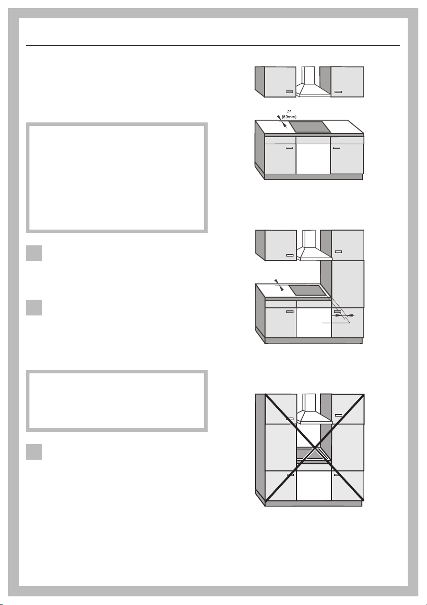
The cooktop should only be
installed as shown in the
illustrations, while maintaining the
required safety distances shown. Do
not install the cooktop between two tall
cabinets, this is a fire hazard.
a A minimum distance of 2"
(50 mm) from the cooktop to the rear
wall and a side wall or cabinet must
be maintained for safety.
To eliminate the risk of burns or fire
by reaching over heated surfaces,
cabinet storage space above the
cooktop should be avoided. If cabinet
storage is necessary, the risk can be
reduced by installing a venting hood to
project horizontally a minimum of 5"
(127 mm) beyond the bottom of the
cabinets.
recommended
2 ”
50mm
b
not recommended
not allowed
3
Page 4
IMPORTANT SAFETY INSTRUCTIONS
This equipment has not been
designed for maritime use or for
use in mobile installations such as
aircraft or recreational vehicles.
However, under certain circumstances
it may be possible for an installation in
these applications. Please contact the
nearest Miele Dealer or the Miele
Technical Service Department with
specific requirements.
Because of the heat radiated from
this type of appliance we do not
recommend installing it over a drawer. It
should be installed in a cabinet base
unit with a dummy drawer front and an
additional protective barrier beneath
the unit.
If there is a drawer directly underneath
the cooktop, do not store aerosols,
combustible liquids or easily flammable
materials in it. If cutlery inserts are
placed in the drawer, they must be heat
resistant.
The cooktop must not be installed
over a dishwasher, washing
machine, dryer, refrigerator or freezer.
The high temperatures radiated
downwards from this type of cooktop
could damage these appliances.
Make sure that the power cord to
the cooktop does not come in
contact with any mechanical parts once
the cooktop has been installed.
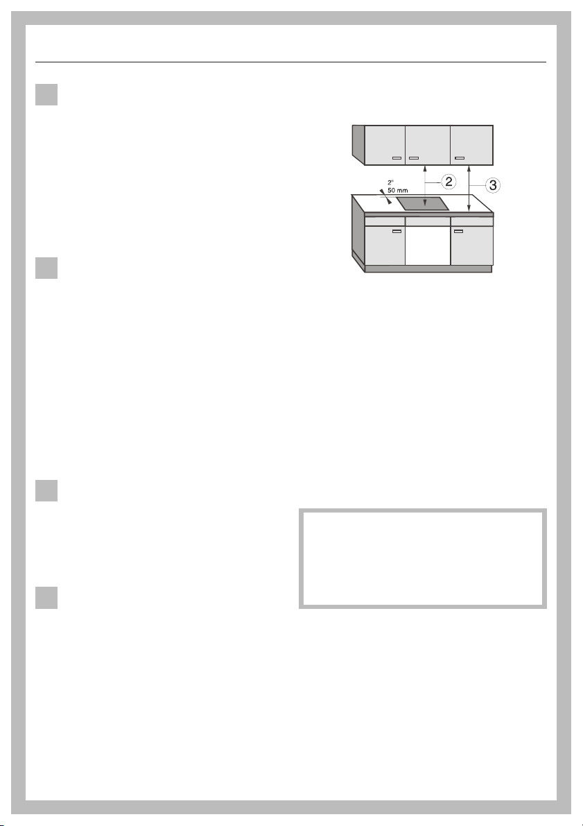
Safety distances above the
appliance
As a general rule there must be a safety
distance of at least 30" (760 mm), b,
between the appliance and any
flammable objects above it, e.g.
cabinetry, venting hood or utensil rail.
The minimum distance of combustible
surfaces located above and to the side
of the cooktop, c, is 18" (457 mm).
If the manufacturer of these items
recommends a different distance, follow
that manufacturers recommendation.
If more than one appliance is
installed beneath a venting hood,
and they have different minimum
safety distances to the hood, select
the higher safety distance of the two.
4
Page 5

KM 421
(8mm)
3
3
"
8
(85mm)
Appliance and cut-out dimensions
3
"
3
8
(85mm)
5
16
"
15
"
16
20
(532mm)
3
24
16
(614mm)
"
b
* max.R3/16
max.R4mm
2
15
(75mm)
16
"
a Spring clips
^
Make the countertop cut-out following
the dimensions given in the
illustration.
^
Remember to maintain a minimum
distance of 2" (50 mm) between the
rear wall and a right or left hand side
wall. See also "Important safety
instructions".
"
(75mm)
2
15
(600mm)
1
"
6
23
"
2
(min.50)
20
3
8
)
m
5
"
8
(518m
b
If, during installation, the seal around
the frame does not sit flush with the
countertop or the corners, the
corner radius max. R4 (
carefully filed down to fit.
*Use max.
3
/8" drill bit.
3
/8") can be
^
Seal the cut surfaces with a suitable
heat resistant sealant to avoid
swelling caused by moisture.
5
Page 6

Appliance and cut-out dimensions
KM 424
5
16
"
(8m
3
3
"
8
(85mm)
* max.R3/16
max.R4mm
(75mm)
m
)
b
"
2
15
16
"
15
"
16
20
(532mm)
2
(75mm)
(749mm)
15
16
"
29
1
"
2
(518mm)
3
20
1
30
"
16
(763mm)
8
2
b
"
min.50
3
"
3
8
(85mm)
a Spring clips
^
Make the countertop cut-out following
the dimensions given in the
illustration.
^
Remember to maintain a minimum
distance of 2" (50 mm) between the
rear wall and a right or left hand side
wall. See also "Important safety
instructions".
^
Seal the cut surfaces with a suitable
heat resistant sealant to avoid
swelling caused by moisture.
6
If, during installation, the seal around
the frame does not sit flush with the
countertop or the corners, the
corner radius max. R4 (
3
/8") can be
carefully filed down to fit.
*Use max.
3
/8" drill bit.
Page 7

KM 427
(8mm)
3
3
8
(85mm)
Appliance and cut-out dimensions
3
"
3
8
(85mm)
5
1
"
6
"
15
"
16
20
(532mm)
9
35
16
"
(903mm)
* max.R3/16
"
max.R4mm
2
2
15
15
(75mm)
1
1
"
"
6
6
b
(75mm)
a Spring clips
^
Make the countertop cut-out following
the dimensions given in the
illustration.
^
Remember to maintain a minimum
distance of 2" (50 mm) between the
rear wall and a right or left hand side
wall. See also "Important safety
instructions".
^
Seal the cut surfaces with a suitable
heat resistant sealant to avoid
swelling caused by moisture.
35
"
(889mm)
2
15
1
"
6
"
2
(min.50)
"
3
8
20
(518mm)
b
If, during installation, the seal around
the frame does not sit flush with the
countertop or the corners, the
corner radius max. R4 (
carefully filed down to fit.
*Use max.
3
/8" drill bit.
3
/8") can be
7
Page 8

Installation
Installing the spring clips
(75mm)
3 ”
b
^ Fix the supplied spring clips, a, at
the marked positions as shown
above, by laying them on the upper
edge of the cut-out and then
securing them with the 3.5 x 25 mm
screws supplied.
Granite countertops
For granite countertops, the spring
clips, b, must be placed in position
and secured with double-sided tape.
In addition, coat the edges of the
spring clips with silicone sealant.
The screws are not needed for granite
countertops.
8
Page 9

Installing the cooktop
Feed the power cord down through
^
the cut-out and connect the
appliance to the power supply.
^ Position the cooktop on the spring
clips, a.
^ Then with a hand on each side of the
cooktop press down on the edges
evenly until it clicks into position.
When doing so make sure that the
cooktop seal sits tightly on the
countertop to ensure a correct seal is
provided.
The cooktop can now only be
removed with a special tool.
Installation
The cooktop must not be
permanently sealed into the
countertop when installed. The
sealing strip under the edge of the
cooktop provides a sufficient seal for
the countertop.
If the cooktop is sealed into position,
the countertop or appliance could be
damaged if the cooktop needs to be
removed for maintenance or service.
9
Page 10

Electrical connection
All electrical work should be by a
qualified electrician in accordance
with local and national codes.
To reduce the risk of electric shock,
disconnect the power supply by
tripping the circuit breaker or
removing the fuse to the unit before
installation or service.
Note to the installer:
^
Please leave these instructions with
the consumer.
Power supply:
Please check the data plate.
KM 421:
– 240 VAC, 60 Hz, 30 A fuse rating
– 208 VAC, 60 Hz, 30 A fuse rating
Important
The appliance is provided with 3 leads;
L1 (black), L2 (red) and GND (green).
They must be connected to a
dedicated line through the use of an
approved junction box.
For further information, see the wiring
diagram provided with the appliance.
WARNING:
THIS APPLIANCE MUST BE
GROUNDED!
KM 424:
– 240 VAC, 60 Hz, 40 A fuse rating
–
208 VAC, 60 Hz, 40 A fuse rating
KM 427:
–
240 VAC, 60 Hz, 50 A fuse rating
–
208 VAC, 60 Hz, 50 A fuse rating
Make sure your electrical supply
matches the data plate.
10
Page 11

11
Page 12

Alterations rights reserved / 0705
M.-Nr. 05 647 580 / 02
en-US
 Loading...