

Operating and Installation instructions
Gas hob
KM 405
KM 406
KM 416
To avoid the risk of accidents or
damage to the appliance it is
essential to read these
instructions before it is installed
or used for the first time.
-CNen
M.-Nr. 06 127 100

Contents
Description of the appliance. . . . . . . . . . . . . . . . . . . . . . . . . . . . . . . . . . . . . . . . . 4
KM 405. . . . . . . . . . . . . . . . . . . . . . . . . . . . . . . . . . . . . . . . . . . . . . . . . . . . . . . . . . . 4
KM 406. . . . . . . . . . . . . . . . . . . . . . . . . . . . . . . . . . . . . . . . . . . . . . . . . . . . . . . . . . . 5
KM 416. . . . . . . . . . . . . . . . . . . . . . . . . . . . . . . . . . . . . . . . . . . . . . . . . . . . . . . . . . . 6
Warning and Safety instructions . . . . . . . . . . . . . . . . . . . . . . . . . . . . . . . . . . . . . 7
Before using for the first time. . . . . . . . . . . . . . . . . . . . . . . . . . . . . . . . . . . . . . . 13
General notes . . . . . . . . . . . . . . . . . . . . . . . . . . . . . . . . . . . . . . . . . . . . . . . . . . . . 13
Disposal of the packing material . . . . . . . . . . . . . . . . . . . . . . . . . . . . . . . . . . . . . . 14
Disposal of your old appliance . . . . . . . . . . . . . . . . . . . . . . . . . . . . . . . . . . . . . . . 14
Cleaning and heating up for the first time . . . . . . . . . . . . . . . . . . . . . . . . . . . . . . . 15
Gas burner unit . . . . . . . . . . . . . . . . . . . . . . . . . . . . . . . . . . . . . . . . . . . . . . . . . . 16
Switching on, Switching off, Controls. . . . . . . . . . . . . . . . . . . . . . . . . . . . . . . . . . . 16
KM 405 / KM 416 . . . . . . . . . . . . . . . . . . . . . . . . . . . . . . . . . . . . . . . . . . . . . . . 16
KM 406 . . . . . . . . . . . . . . . . . . . . . . . . . . . . . . . . . . . . . . . . . . . . . . . . . . . . . . . 17
Using the gas hob . . . . . . . . . . . . . . . . . . . . . . . . . . . . . . . . . . . . . . . . . . . . . . . . 18
Suitable pans . . . . . . . . . . . . . . . . . . . . . . . . . . . . . . . . . . . . . . . . . . . . . . . . . . . . . 18
Safety cut-out. . . . . . . . . . . . . . . . . . . . . . . . . . . . . . . . . . . . . . . . . . . . . . . . . . . . . 19
Use during a power cut . . . . . . . . . . . . . . . . . . . . . . . . . . . . . . . . . . . . . . . . . . . . . 19
Cleaning and care . . . . . . . . . . . . . . . . . . . . . . . . . . . . . . . . . . . . . . . . . . . . . . . . 20
Ceramic hob surface . . . . . . . . . . . . . . . . . . . . . . . . . . . . . . . . . . . . . . . . . . . . . . . 20
Burners . . . . . . . . . . . . . . . . . . . . . . . . . . . . . . . . . . . . . . . . . . . . . . . . . . . . . . . . . 21
Problem solving guide. . . . . . . . . . . . . . . . . . . . . . . . . . . . . . . . . . . . . . . . . . . . . 25
After sales service, data plate. . . . . . . . . . . . . . . . . . . . . . . . . . . . . . . . . . . . . . . 26
2

Contents
Installation . . . . . . . . . . . . . . . . . . . . . . . . . . . . . . . . . . . . . . . . . . . . . . . . . . . . . . 27
Safety instructions . . . . . . . . . . . . . . . . . . . . . . . . . . . . . . . . . . . . . . . . . . . . . . . . . 27
Safety distance above appliances . . . . . . . . . . . . . . . . . . . . . . . . . . . . . . . . . . 28
Building-in dimensions . . . . . . . . . . . . . . . . . . . . . . . . . . . . . . . . . . . . . . . . . . . . . 29
KM 405 . . . . . . . . . . . . . . . . . . . . . . . . . . . . . . . . . . . . . . . . . . . . . . . . . . . . . . . 29
KM 406 . . . . . . . . . . . . . . . . . . . . . . . . . . . . . . . . . . . . . . . . . . . . . . . . . . . . . . . 30
KM 416 . . . . . . . . . . . . . . . . . . . . . . . . . . . . . . . . . . . . . . . . . . . . . . . . . . . . . . . 31
Worktop cut-out . . . . . . . . . . . . . . . . . . . . . . . . . . . . . . . . . . . . . . . . . . . . . . . . . . . 32
Fitting the spacer bars and support brackets . . . . . . . . . . . . . . . . . . . . . . . . . . . . 33
Fixing the spacer bars . . . . . . . . . . . . . . . . . . . . . . . . . . . . . . . . . . . . . . . . . . . . . . 34
Fixing the support brackets . . . . . . . . . . . . . . . . . . . . . . . . . . . . . . . . . . . . . . . . . . 35
Building in the gas hob . . . . . . . . . . . . . . . . . . . . . . . . . . . . . . . . . . . . . . . . . . . . . 35
Electrical connection . . . . . . . . . . . . . . . . . . . . . . . . . . . . . . . . . . . . . . . . . . . . . . 37
Gas connection . . . . . . . . . . . . . . . . . . . . . . . . . . . . . . . . . . . . . . . . . . . . . . . . . . . 40
Town gas / LPG / Natural gas . . . . . . . . . . . . . . . . . . . . . . . . . . . . . . . . . . . . . . . . 41
Conversion to another type of gas. . . . . . . . . . . . . . . . . . . . . . . . . . . . . . . . . . . 42
KM 405. . . . . . . . . . . . . . . . . . . . . . . . . . . . . . . . . . . . . . . . . . . . . . . . . . . . . . . . . . 42
Jet table . . . . . . . . . . . . . . . . . . . . . . . . . . . . . . . . . . . . . . . . . . . . . . . . . . . . . . 42
Changing the jets . . . . . . . . . . . . . . . . . . . . . . . . . . . . . . . . . . . . . . . . . . . . . . . 43
KM 406. . . . . . . . . . . . . . . . . . . . . . . . . . . . . . . . . . . . . . . . . . . . . . . . . . . . . . . . . . 44
Jet table . . . . . . . . . . . . . . . . . . . . . . . . . . . . . . . . . . . . . . . . . . . . . . . . . . . . . . 44
Changing the jets . . . . . . . . . . . . . . . . . . . . . . . . . . . . . . . . . . . . . . . . . . . . . . . 45
Check the first intake of air . . . . . . . . . . . . . . . . . . . . . . . . . . . . . . . . . . . . . . . . 48
KM 416. . . . . . . . . . . . . . . . . . . . . . . . . . . . . . . . . . . . . . . . . . . . . . . . . . . . . . . . . . 49
Jet table . . . . . . . . . . . . . . . . . . . . . . . . . . . . . . . . . . . . . . . . . . . . . . . . . . . . . . 49
Changing the jets . . . . . . . . . . . . . . . . . . . . . . . . . . . . . . . . . . . . . . . . . . . . . . . 50
Check the first intake of air . . . . . . . . . . . . . . . . . . . . . . . . . . . . . . . . . . . . . . . . 52
3
Description of the appliance
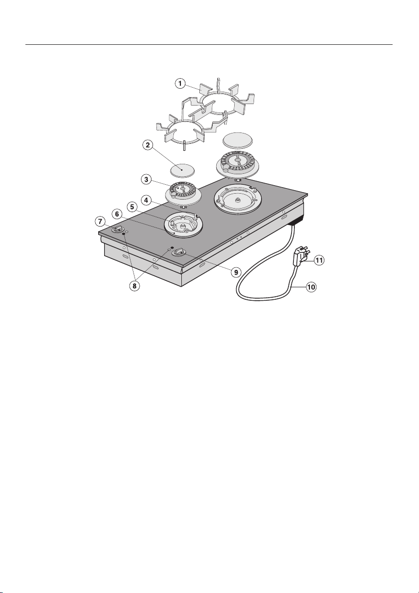
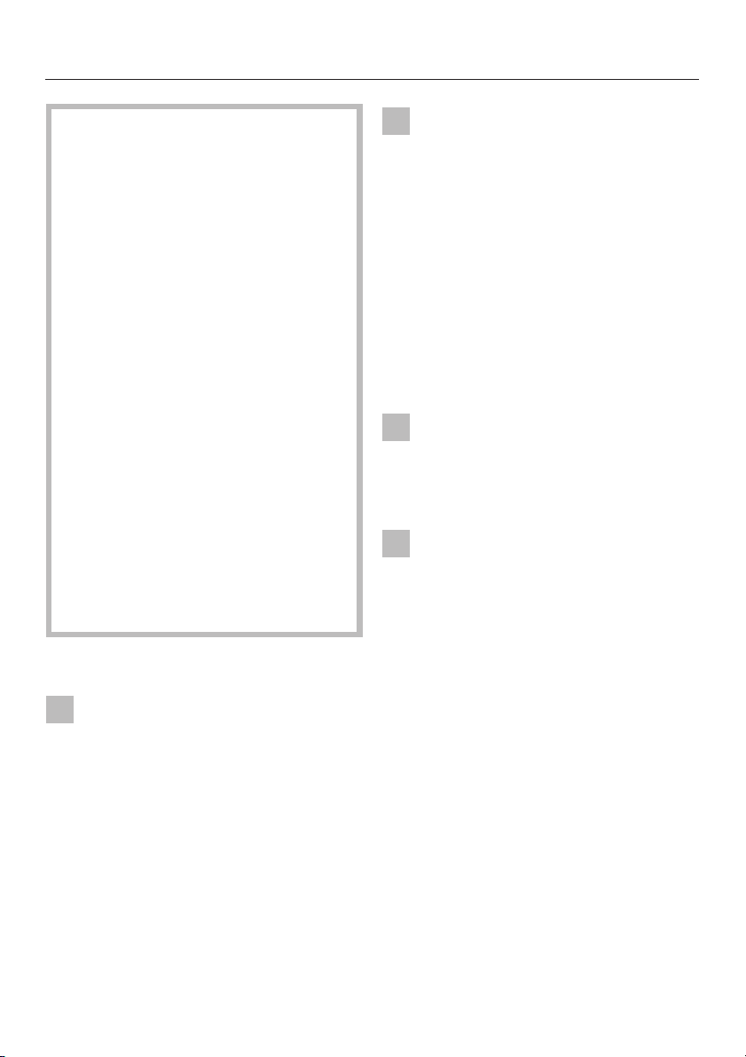
KM 405
a Pan support
b Burner cap
c Burner head
d Ignition safety device
e Ignitor
f Burner base
4
g Control knob for the
front burner
h Symbols to indicate which
cooking zone the control is for
i Control knob for the
back burner
j Mains connection cable
k Plug
Depending on country of destination,
the appliance may be supplied with
or without a plug. The plug shown is
for illustration only.
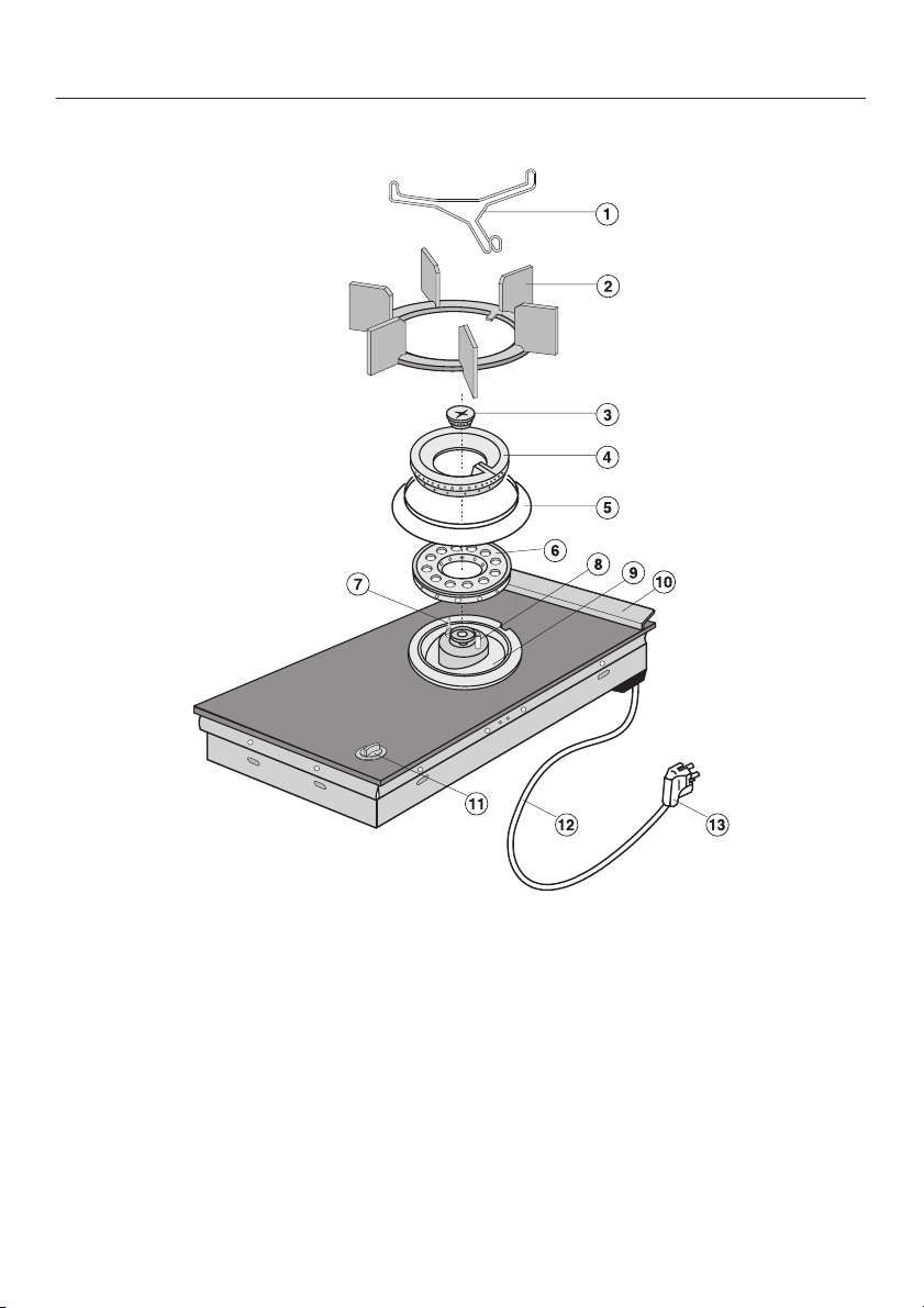
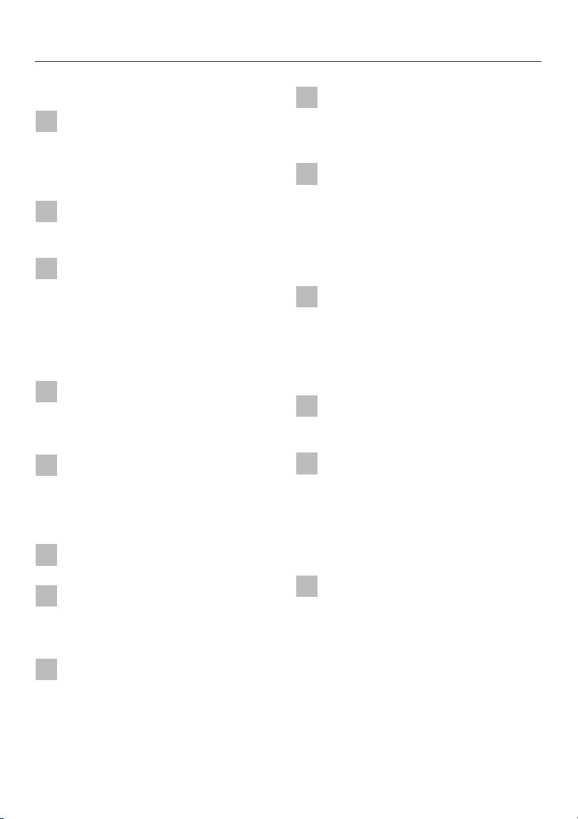
KM 406
Description of the appliance
a Trivet
b Pan support
c Small burner cap
d Large burner cap
e Burner collar ring
f Large burner cap base
g Ignition safety device
h Ignitor
i Burner base
j Air inlet with cover plate
k Control for burner
l Mains connection cable
m Plug
Depending on country of destination,
the appliance may be supplied with
or without a plug. The plug shown is
for illustration only.
5
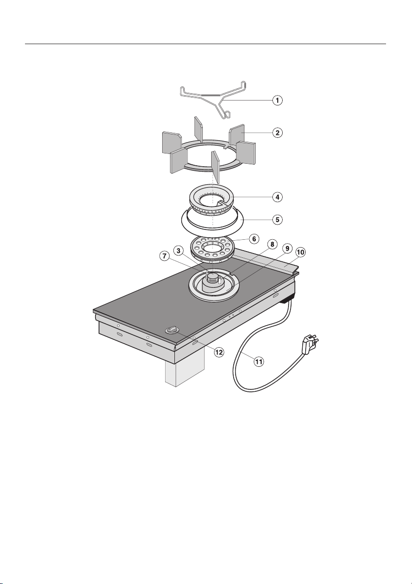
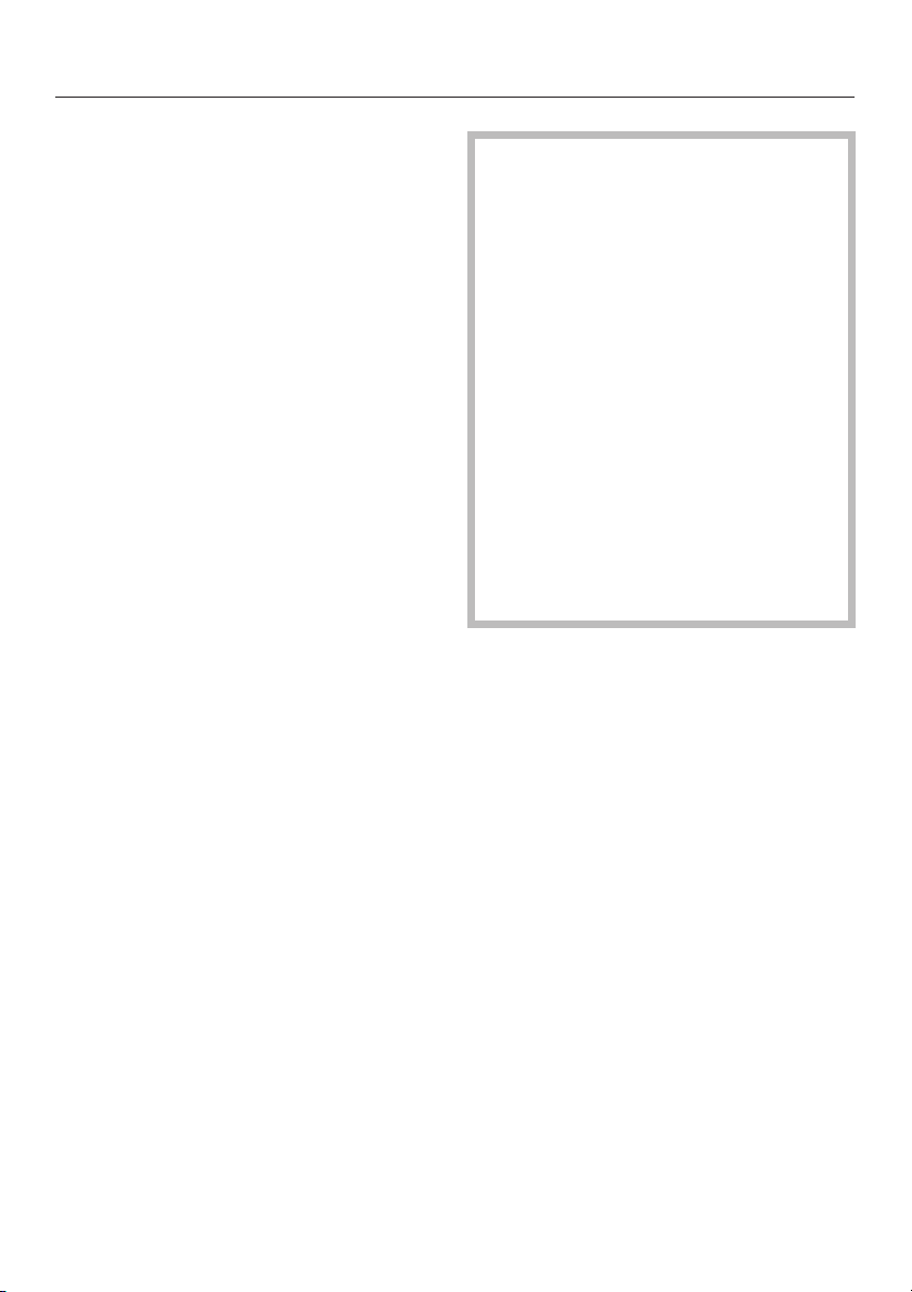
Description of the appliance
KM 416
a Trivet
b Pan support
c Air inlet cover for inner burner circle
d Large burner cap
e Burner collar ring
f Large burner cap base
g Ignition safety device
h Ignitor
6
i Burner base
j Air inlet with cover plate
k Cable for connection to electrical
supply approx. 3.5 ft (1.10m) long
(** See note on Contents page)
l Control for burner
Warning and Safety instructions
This appliance complies with all
relevant legal safety requirements.
Improper use of the appliance can,
however, present a risk of both
personal injury and material
damage.
Before installing and using the
appliance for the first time, read the
operating and installation
instructions carefully. They give
information on safety, on the
operation and care of the appliance.
This way you will avoid the risk of
accident and damage to the
appliance.
Do not let children access the
appliance or its controls. Supervise
its use by the elderly or infirm.
Keep these instructions in a safe
place for reference and pass them
on to any future user.
The electrical safety of this
appliance can only be guaranteed
when continuity is complete between
the appliance and an effective earthing
system.
It is imperative that this basic safety
requirement be tested and where there
is any doubt, the electrical system of
the house should be checked out by a
qualified electrician. The manufacturer
cannot be held liable for damage such
as electric shock caused by the lack or
inadequacy of an effective earthing
system.
Ensure that the gas pipe and
electrical cable are installed in
such a way that they do not touch any
parts of the appliance which become
hot. This could cause damage.
Do not connect the appliance to
the mains electricity supply by an
extension lead. Extension leads do not
guarantee the required safety of the
appliance.
Technical safety
The connection to the gas supply
must be carried out by a suitably
qualified and competent person in
accordance with local and national
safety regulations. If the appliance is
supplied without a plug, or if the plug is
removed the appliance must
additionally be installed and connected
by a suitably qualified and competent
electrician in strict accordance with
national and local regulations. The
manufacturer cannot be held liable for
damage caused by incorrect
installation or connection.
7
Warning and Safety instructions
Correct usage
For safety reasons the appliance
must only be operated after it has
been built in. This is necessary to
ensure that all electric components are
shielded.
This appliance is for domestic use
only, and is not intended for
commercial use.
Use this appliance for the
preparation of meals only. Any
other usage is at the owner’s risk and
could be dangerous. The manufacturer
can not be held liable for damage
caused by improper use or misuse of
the appliance.
Do not use the appliance to heat
up the room. The high temperature
could cause inflammable objects
nearby to catch fire.
Ensure the room in which the gas
hob is installed has sufficient
ventilation. In a small kitchen it may be
advisable to keep the door open if
using the hob for extended periods.
This appliance must not be set up
or operated in the open air.
Make sure all the components of
the gas burners have been
correctly assembled before switching
on.
Do not store any inflammable
objects near the gas hob.
KM 405
Only use pans with a base
diameter of maximum 22 cm (front
burner) and 24 cm (rear burner) on this
hob. Using larger pans may cause the
flames to spread out to the sides and
damage or burn the worktop, wall
claddings or surrounding units.
For safety and stability use only
pans with a minimum base
diameter of 12 cm (front burner) and 14
cm (rear burner).
KM 406 / KM 416
Ensure that the air inlet is never
covered over with a cloth or
anything else.
Only use woks or pans with a base
diameter between 16 cm and
maximum 28 cm on this hob. Using
larger pans may cause the flames to
spread out to the sides and damage or
burn the worktop, wall claddings or
surrounding units.
For safety and stability use the
trivet for pans with a base diameter
of less than 16 cm.
When using a cooker hood over
the gas hob, ensure that any
burners in use are always covered with
a pan. Otherwise flames could be
drawn up by the suction of the cooker
hood, parts of which could then be
damaged or even set on fire.
8

Warning and Safety instructions
Protecting the appliance from
damage
Do not drop anything on the
ceramic surface of the hob. Even a
light object such as a salt cellar could
cause damage in certain
circumstances.
Unless the pan manufacturer
states that you can do so, you
should never use pans with thin bases
on this hob and you should never heat
up an empty pan. Otherwise the hob
could get damaged.
Under no circumstances use a
steam cleaning appliance to clean
the gas hob. Pressurised steam could
cause permanent damage to the
surface and to components, for which
the manufacturer cannot accept
responsibility.
In countries which may be subject
to infestation by cockroaches or
other vermin, pay particular attention to
keeping the appliance and its
surroundings in a clean condition at all
times. Any damage which might be
caused by cockroaches or other vermin
will not be covered by the appliance
guarantee.
Protection from burning
Do not let small children use the
appliance or touch it during
operation. The burner support, trivet,
burners and also the ceramic surfaces
around the burners heat up and remain
hot for quite a while after the appliance
has been switched off. Danger of
burning. Do not touch them until they
have cooled down. The use of oven
gloves is recommended.
Do not store anything which might
arouse a child’s interest in storage
areas above or next to the hob.
Otherwise they could be tempted into
climbing onto the appliance with the
risk of burning themselves.
Use heat-resistant pot holders or
gloves when handling hot pots and
pans. Ensure that the pot holders do
not come into contact with the flames.
Do not use large cloths, tea towels or
similar as the ends could touch the
flames and catch fire. Take care not to
let pot holders or gloves get damp or
wet, as this causes heat to transfer
through the material quicker with the
risk of burning yourself.
To prevent the risk of children
reaching pan handles and pulling
pans over with the danger of burning or
scalding themselves be sure to turn
pan handles inwards and out of their
reach. Special hob guards are available
from good retail outlets as additional
protection.
9

Warning and Safety instructions
Do not heat up unopened tins of
food on the hob as pressure will
build up in the tin and it can explode.
This could result in injury or damage.
Do not use the hob as a resting
place for anything else. If the hob
was switched on inadvertently, or if it
was still hot the article could begin to
melt or catch fire.
Remove splashes of fat and other
food debris from the surface as
soon as possible. These are a fire
hazard.
Do not cover the hob with a cloth,
household foils or other similar
objects. This could lead to danger of
the article catching fire, if the hob were
to be switched on inadvertently.
Never leave the hob unattended
when cooking with oil or fats as
these are fire hazards if overheated.
Overheated fat could catch fire and
even set the cooker hood on fire.
Do not flambé under a cooker
hood. Otherwise flames could be
drawn up by the suction of the cooker
hood, parts of which could then be
damaged or even set on fire.
Ensure that the flames from the
burner does not spread out
beyond the base and up the sides of
the pan.
Spray canisters, aerosols and other
inflammable substances should not
be stored in a drawer under the hob if
there is no shelf separating the drawer
from the hob. If cutlery inserts are to be
placed in the drawer these must be
made of a suitable heat-resistant
material.
If oil or fat does catch fire despite
this do not attempt to put out the
flames with water. Use a suitable fire
blanket or fire extinguisher.
10

Warning and Safety instructions
With a damaged appliance
In the event of damage or a defect,
switch off the appliance immedi
ately. Turn off the gas supply tap, and
disconnect completely from the
electricity supply. Contact the Service
department.
Ensure that the appliance is
disconnected from the electricity
supply before any servicing or repair
work.
Any breakages or cracks in the
ceramic surface of the hob are
defects and must be treated as such.
Repairs to the gas and electrical
components of this appliance must
only be carried out by a suitably
qualified person. Repairs by
unauthorised personnel could be
dangerous. On no account open the
outer casing of the appliance.
While the appliance is under
guarantee repairs should only be
undertaken by a service engineer
authorised by the manufacturer.
Otherwise the guarantee is invalidated.
11

Warning and Safety instructions
Further safety notes
When using an electric socket near
the hob, care should be taken that
the cable of the electrical appliance
does not come into contact with the gas
flames or the hot parts of the hob. The
insulation on the cable could become
damaged, giving rise to an electric
shock hazard.
Always ensure that food is
sufficiently cooked or reheated.
Some foods may contain micro
organisms which are only destroyed by
thorough cooking, therefore when
cooking or reheating foods, e.g. poultry,
select a longer cooking or reheating
time.
Do not use plastic or aluminium foil
containers. These melt at higher
temperatures and could damage the
ceramic surface. Fire hazard.
Before disposing of an old
appliance, ensure that
disconnection from the gas supply is
made by a suitably competent person.
Switch off at the mains electricity
supply. Cut off and render any plug
useless. Cut off the cable directly
behind the appliance to prevent
misuse. Ensure that the appliance
presents no danger to children while
being stored for disposal.
12

General notes
A data plate for your appliance is
supplied with this documentation. It
should be stuck into the space
provided at the end of the instruction
book. The address of the nearest Ser
vice Department is given on the back
page.
Before using for the first time
-
13
Before using for the first time
Disposal of the packing
material
The transport and protective packing
has been selected from materials which
are environmentally friendly for disposal
and can normally be recycled.
Ensure that any plastic wrappings,
bags etc. are disposed of safely and
kept out of the reach of babies and
young children. Danger of suffocation!
Rather than just throwing these
materials away, please ensure that they
are offered for recycling.
Disposal of your old appliance
Old appliances contain materials which
can be reclaimed or recycled. Please
contact your dealer, your local waste
collection centre or scrap merchant
about potential recycling schemes.
Before disposing of an old
appliance, ensure that
disconnection from the gas supply is
made by a suitably qualified and
competent person. Switch off at the
mains electricity supply. Cut off and
render any plug useless. Cut off the
cable directly behind the appliance
to prevent misuse. This should be
done by a competent person.
Ensure that the appliance presents
no danger to children while being
stored for disposal.
The manufacturer cannot be held
liable for damage caused by
non-compliance with these safety
instructions.
14
Before using for the first time
Cleaning and heating up for
the first time
Before using for the first time clean the
hob and all removable parts as follows:
The removable parts of the gas
^
burner assembly can be washed in a
mild solution of water and
washing-up liquid. Wipe dry and
reassemble in the correct order (see
"Cleaning and care").
Clean the ceramic surface with a
^
damp cloth only, and then wipe dry.
Do not use washing up liquid on the
ceramic surface as it can leave a
blue sheen on the surface which
may be difficult to remove.
Metal components have a protective
coating which may give off a slight
smell when the hob is heated up for the
first time. The smell and any vapours
will dissipate after a short time and do
not indicate a faulty connection or
appliance.
15
Gas burner unit
Switching on, Switching off,
Controls
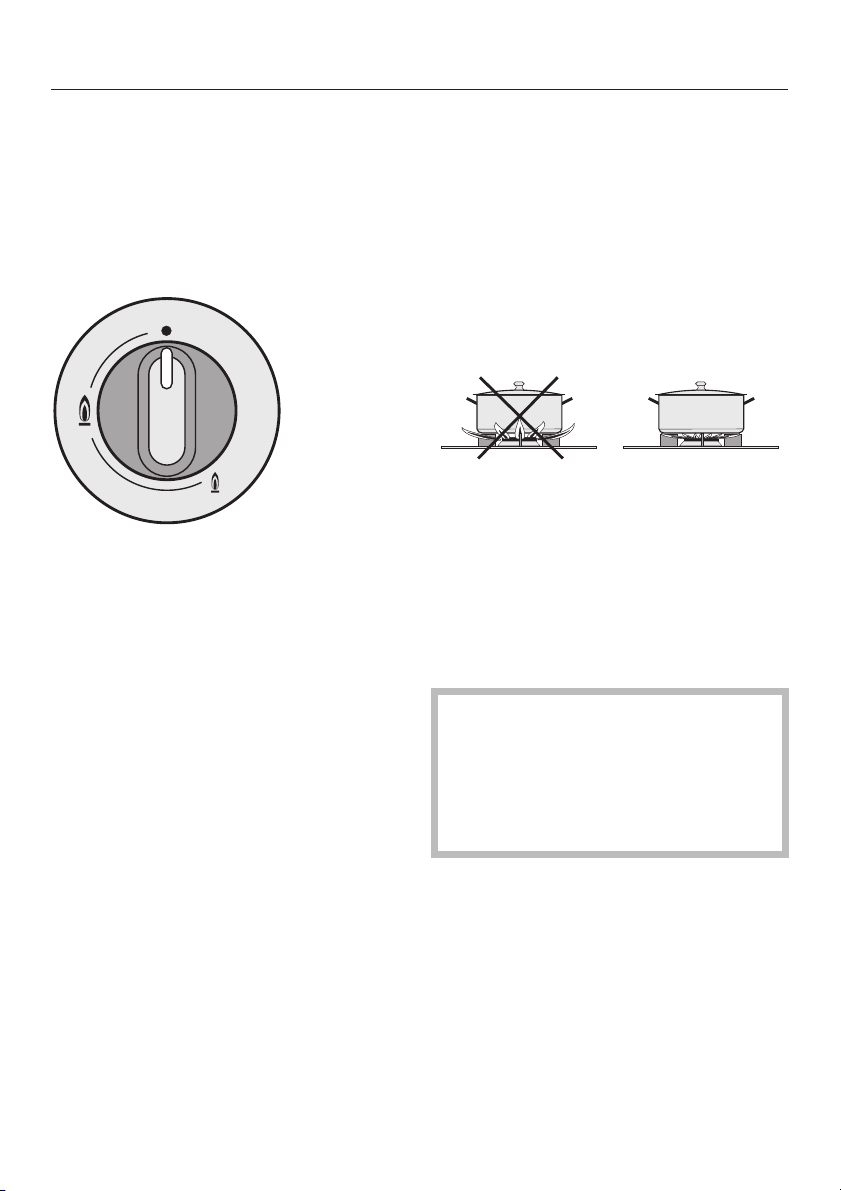
The control knob is used to switch on
the burner and regulate the strength of
the flame.
KM 405 / KM 416
ß the gas supply is turned off
& strong flame
/ weak flame
Switching on:
Control the flame so that it does not
spread out beyond the sides of the
pan. As the outer part of the flame is
much hotter than the centre, the tips of
the flames should stay beneath the pan
base. Flame tips which extend beyond
the sides of the pan merely warm up
the air in the room and can also
damage pan handles and increase the
danger of burning.
Switching off:
^ Turn the knob clockwise until the ß
position is reached.
This stops the flow of gas and the flame
goes out.
^ Press in the control and then turn
anti-clockwise to the large flame
symbol.
^
When the flame ignites, keep the
control pressed in for 8-10 seconds,
and then let it go.
If the flame goes out, repeat the
procedure, keeping the control knob
pressed in for a few extra seconds.
^
With the knob no longer pressed in
you can continue turning it towards
the small flame symbol.
16
Remember: Turn anti-clockwise to
switch on, turn clockwise to switch
off.
The control knob cannot be turned
anti-clockwise from the small flame
symbol to the "ß" position.
Gas burner unit
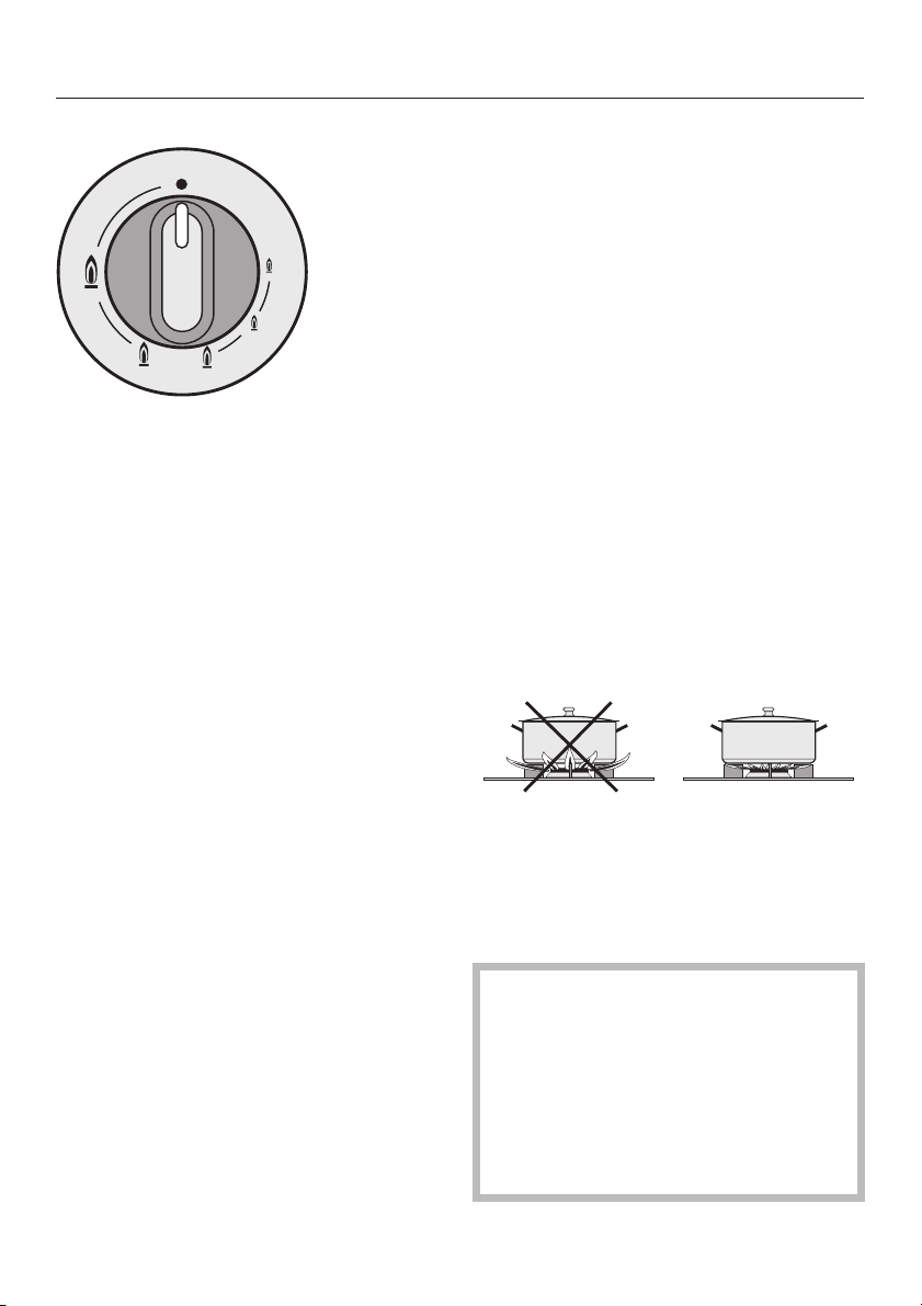
KM 406
ß gas is turned off
* strongest flame
outer and inner rings both produce
high flames
& (2x)strong flame
outer flame ring burns on low,
inner flame ring burns on high
+ low flame
inner flame ring burns on high
/ very low flame
inner flame ring burns on low
resistance. Briefly press to turn past
the resistance. Then without pressing
it in turn the control to the required
setting.
To turn the heat up from a low to a
^
high setting, turn the control
clockwise until there is a resistance.
Briefly press to turn past the
resistance. Then without pressing it in
turn the control to the required
setting.
Control the flame so that it does not
spread out beyond the sides of the
pan. As the outer part of the flame is
much hotter than the centre, the tips of
the flames should stay beneath the pan
base. Flame tips which extend beyond
the sides of the pan merely warm up
the air in the room and can also
damage pan handles and increase the
danger of burning.
Switching on:
^
Press in the control and then turn
anti-clockwise to the large flame
symbol.
^
When the flame ignites, keep the
control pressed in for 8-10 seconds,
and then let it go.
If the flame goes out, repeat the
procedure, keeping the control knob
pressed in for a few extra seconds.
To regulate the burner setting:
^
To turn the heat down from a high to
a low setting turn the control
anti-clockwise until there is a
Switching off:
^
Turn the control clockwise until "ß" is
reached.
This stops the flow of gas and the flame
goes out.
Remember: Turn anti-clockwise to
switch on, turn clockwise to switch
off.
Stop when you feel a resistance. Do
not try to force the control further.
The control cannot be turned
anti-clockwise from the small flame
symbol to the "ß" position.
17

Using the gas hob
Suitable pans
Any heat-resistant pans can be used on
a gas burner.
Pan bases do not need to be even for
cooking, (in contrast with those used on
an electric hob). Through the spreading
action of the flame, heat reaches all
parts of the base.
Thick pan bases reduce the risk of food
overheating in places, as heat is better
distributed.
Thin pan bases conduct heat to the
food inside more quickly than thicker
ones. However as the heat is not evenly
distributed over the pan base there is a
danger that food may heat up unevenly.
Stir the food frequently.
Pan size
The simple rule: a large pan for the
large flame, a small pan for the small
flame.
Wide, shallow pans are preferable to
narrow, tall ones. They heat up more
quickly as there is room for more flame
under the base.
KM 405
The base diameter of the pan should
–
not exceed 22 cm for the front burner
and 24 cm for the rear burner.
Using larger pans may cause the
flames to spread out to the sides and
damage or burn the worktop, wall
claddings or surrounding units.
For safety and stability, please use
–
pans with a minimum base diameter
of 12 cm for the front burner and 14
cm for the rear burner.
KM 406 / KM 416
– The base diameter of the pan or wok
should not exceed 28 cm.
Using larger pans may cause the
flames to spread out to the sides and
damage or burn the worktop, wall
claddings or surrounding units.
– For safety and stability, please use
the trivet for pans with a base
diameter less than 16 cm.
When using smaller pans you should
always turn the hob control to the
lowest setting. If it is too high flames
can lick up the sides of the pan!
18

Using the gas hob
Safety cut-out
This appliance is fitted with an electric
ignition safety device which cuts off the
supply of gas to a burner if the flame
goes out, for example if food has boiled
over, or if there was a sudden draught.
To use the hob again, turn the knob
^
clockwise until the ß position is
reached and switch on as normal.
The safety cut-out operates
independently from the electricity
supply. This means that it is still active
when the hob is used during a power
cut (see "Use during a power cut").
Use during a power cut
If there is an interruption to the
electricity supply the gas can be
ignited with a match:
Press in the relevant control knob and
^
turn it anti-clockwise to the large gas
symbol.
Hold the control pressed in and light
^
the gas at the burner with a match.
Keep the control knob pressed in for
^
a further 8-10 seconds and then
release it.
19

Cleaning and care
Under no circumstances use a
steam cleaner to clean this
appliance. Pressurised steam could
cause permanent damage to the
surface and to components for
which the manufacturer cannot
accept liability.
Do not use any sharp objects which
could damage the seal between the
ceramic surface and the
surrounding frame and between the
frame and the worktop.
Never use aggressive or abrasive
cleaning agents, e.g. grill and oven
sprays, stain or rust removers,
scouring agents or abrasive
sponges.
Do not use washing up liquid on the
ceramic surface as it can leave a
blue sheen on the surface which
may be difficult to remove.
Ceramic hob surface
The ceramic surface should be cleaned
regularly, preferably after each use.
Before cleaning, allow the hob to cool
down. Once it has cooled down, wipe
soiling off using a damp cloth. Stubborn
soiling is best removed with a shielded
scraper blade.
Then apply a proprietary cleaning
agent for ceramic surfaces using a soft
cloth or kitchen paper towel. This way
any limescale deposits, caused for
example by water boiling over, are
removed.
Finally wipe the hob surface with a
damp cloth and then dry it with a clean
soft cloth.
Note that some cleaning agents contain
a protective additive designed to
prevent water marks and smears
adhering to the surface.
The ceramic surface can be cleaned
using a proprietary cleaner for
ceramic surfaces. Follow the
manufacturer’s instructions on the
packaging.
Do not let the ignitor in the burner
get wet. If it gets wet it will not spark.
After cleaning the ceramic surface it
must be thoroughly dried with a soft
cloth to prevent a build up of
limescale deposits.
20

Cleaning and care
Burners
The burners can be dismantled for
cleaning once they have cooled down.
Proceed as follows:
Take off all the removable parts of the
^
burner and wash in a solution of hot
water and washing-up liquid. Then
dry them all thoroughly. Make sure
that the flame holes are clean and
completely dry.
The surface of the burner cover will
gradually become more matt with time.
This is quite normal and will not affect
the operation of the hob.
Wipe the fixed parts of the burner
^
base with a damp cloth and dry
afterwards.
Gently wipe the ignitor and the
^
ignition safety device with a well
wrung-out cloth and wipe dry with a
clean cloth.
21

Cleaning and care
KM 405 Re-assemble the burner as follows:
(see illustration):
Make sure that all the locating tabs
^
and notches line up exactly. Place
the burner head c on to the burner
base f so that the ignitor and the
ignition safety control extend through
their respective holes in the burner
head. The burner head must click
into place correctly.
Replace the burner cap b ensuring
^
that the locating tabs fit into the
notches in the burner head.
Make sure that the parts of the burner
are re-assembled in the correct order
after cleaning.
Important:
1. Do not mix up the top and bottom.
2. The locating lugs must fit exactly
into the notches.
22

Cleaning and care
KM 406 Re-assemble the burner as follows:
(see illustration):
Fit the large burner cap base on to
^
the burner base a.
Fit the burner collar ring.
^
Fit the large burner cap on the large
^
burner cap base b.
Fit the small burner cap.
^
Put the pan support in place c.
^
Put the trivet in place if required.
^
Make sure that the parts of the burner
are re-assembled in the correct order
after cleaning.
Important:
1. Do not mix up the top and bottom.
2. The locating lugs must fit exactly into
the notches.
23

Cleaning and care
KM 416 Re-assemble the burner as follows :
(see illustration):
Fit the large burner cap base on to
^
the burner base a.
Fit the burner collar ring e.
^
Put the large burner cap on the large
^
burner cap base b.
Put the pan support in place c.
^
Put the trivet in place if required.
^
Make sure that the parts of the burner
are re-assembled in the correct order
after cleaning.
Important:
1. Do not mix up the top and bottom.
2. The locating lugs must fit exactly
into the notches.
24

Repairs to the gas and electrical
components of this appliance must
only be carried out by a suitably
qualified and competent person to
ensure safety. Unauthorised repairs
could be dangerous.
However, some minor problems can be
resolved as follows:
What to do if ...
Problem solving guide
... the gas flame goes out after being
lit
Check whether the burner cover is
correctly assembled.
... the ignitor on the burner does not
spark?
Check whether food deposits have
lodged themselves between the ignitor
and the burner cover.
Carefully remove any soiling. Do not let
the ignitor get wet.
... the burner does not ignite after
several attempts
Check whether
– The burner is correctly assembled.
– The gas supply tap is turned on.
– The burner is dry and clean.
– The flame slits are clean and
unblocked.
–
The mains fuse has blown. If this is
the case, call an electrician or the
Service Department. (The gas can
be lit with a match). (See "Use during
a power cut").
... the flame suddenly looks different
Check whether the burner is correctly
assembled.
25

After sales service, data plate
In the event of any faults which you cannot remedy yourself, please contact
Your Miele Dealer
–
or
The Miele Service Department (see address on back cover).
–
When contacting the Service Department, please quote the model and serial
number of your appliance. These are given on the data plate.
Space in which to stick the extra data plate supplied with the appliance. Ensure
that the model number is the same as the one on the front of these operating
instructions.
Please note that telephone calls may be monitored and recorded to improve
our service.
26

Safety instructions
Fit wall units and cooker hood before
fitting the gas hob, to avoid
damaging the hob.
Installation
The room in which the gas hob is
installed must be at least 20 m
size with a door or window in it which
can be opened to the outside air.
The veneer or laminate coatings of
worktops (or adjacent kitchen
units) must be treated with 100°C
heat-resistant adhesive which will not
dissolve or distort.
Any backmoulds must be of heat
resistant material.
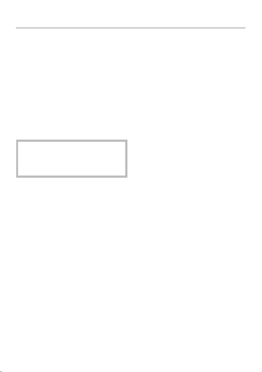
Ideally the hobs should be installed
with plenty of space on either side.
There may be a wall at the rear and wall
or tall units at one side. On the other
side however, no unit or divider should
stand higher than the hob.
Due to the heat radiated by the hob
and to allow cooking fumes to
dissipate it is essential that a
minimum safety distance a is
maintained between the worktop
cut-out and adjacent furniture, e.g. a
tall unit, as follows:
100 mm with KM 405
250 mm with KM 406 / 416.
There must be a minimum safety
distance of 50 mm between the hob
and a back wall.
3
in
recommended
not recommended
not allowed
27

Installation
An electric fryer must not be
installed next to a gas hob, as the
gas flames could ignite the fat in the
fryer.
It is essential to maintain a distance of
at least 288 mm between these two
appliances.
These appliances must not be
installed over a dishwasher,
washing machine, tumble dryer,
refrigerator or freezer. The high
temperatures radiated by hobs could
damage the appliance below.
This equipment is not designed for
maritime use or for use in mobile
installations such as caravans, aircraft
etc. However it may be suitable for
such usage subject to a risk
assessment of the installation being
carried out by a suitably qualified
engineer.
Spray canisters, aerosols and other
inflammable substances must not
be stored in a drawer under the hob.
Cutlery inserts must be heat-resistant.
Safety distance above appliances
A minimum safety distance b must be
maintained between the hob and the
cooker hood above it. See the
manufacturer’s operating and
installation instructions for details. For
any flammable objects, e.g utensil rails,
wall units etc. a minimum safety
distance of at least 760 mm should be
maintained between it and the hob
below.
When two or more appliances are
installed together below a cooker
hood, e.g. a ceramic combiset and
a gas wok combiset, which have
different safety distances given in
their installation instructions you
should select the greater distance of
the two.
28
All dimensions in this instruction booklet
are given in mm.
Keep these instructions in a safe place
and pass them on to any future owner
of the appliance.

Building-in dimensions
KM 405
Installation
a Support bracket
b Building in height plus 3 mm for fixing screw
c Front
d Building in height - Mains connection box
e Gas connection
29

Installation
KM 406
a Support bracket
b Building in height plus 3 mm for fixing screw
30

KM 416
Installation
a Support bracket
31

Installation
Worktop cut-out
Number
of
appliances
Worktop cut-out
Depth
in mm
± 1 mm
Width
(= Dim. B)
in mm
± 1 mm
Dimensions 7 mm and 11 mm are the
space taken up by the frame of the
appliance on the worktop.
^ Make a cut-out for the hob in the
worktop, paying attention to the
appliance height. See "Building-in
dimensions".
Dimension "B" applies to a combination
of appliances and is shown on the
chart.
^
There must be a minimum safety
distance of 50 mm between the hob
and the back wall and 100 mm
distance from a side wall to the right
or left of the hob ( 250 mm for
KM 406, KM 416).
(See "Warning and Safety
instructions")
1
2
3
4
5
6
7
500
500
500
500
500
500
500
266
554
842
1130
1418
1706
1994
Important:
The maximum tolerance for the worktop
cut-out must not exceed ±1 mm.
When building in several combiset
appliances a spacer bar must be
fitted between each unit. See "Fitting
the spacer bars and support
brackets".
^
Seal the cut surfaces with a suitable
sealant to avoid swelling caused by
moisture.
The materials used must be heat
resistant.
32

Fitting the spacer bars and
support brackets
Installation
a Support brackets
b Spacer bars
Installation of several appliances
The illustration above shows an
example of a worktop cut-out with
spacer bars b and support brackets a
for 3 appliances.
For more than 3 appliances, repeat
dimension 288 mm.
The worktop cut-out dimensions for
several appliances are shown in the
table on the previous page.
c Gap between spacer bar and
worktop.
d Drilling for a granite worktop.
^
Fix the spacer bars b and the
support brackets a supplied to the
positions indicated. See "Fixing the
spacer bars" and "Fixing the support
brackets".
33

Installation
Fixing the spacer bars
d
c
The spacer bar is only required when
combined with another appliance.
^ Position the spacer bars b in the
positions shown in "Fitting the spacer
bars and support brackets" so they
are flush with the top edge of the
cut-out and secure using the
3.5 x 25 mm screws supplied.
Granite worktops
With granite worktops the spacer bars
b must be positioned and secured with
strong double-sided adhesive tape. In
addition, coat the edges with silicone
and fill in the gap c.
The screws are not required for granite
tops.
^
Then fill in the gap c between the
bars and the worktop with silicone
from the tube supplied.
34

Installation
Fixing the support brackets
^ Position the two support brackets
supplied a in the positions shown in
"Fitting the spacer bars and support
brackets" so they are flush with the
top edge of the cut-out and secure
using the 3.5 x 25 mm screws
supplied. 2 screws are needed to
secure each support bracket.
The thickness of the worktop will
determine which drill hole is used.
Granite worktops
On a granite worktop a hole must be
drilled d at the position indicated to
secure each support bracket.
Using a piece of strong, double-
^
sided adhesive tape position the
support brackets supplied a at the
positions indicated flush with the top
edge of the worktop and secure each
bracket with one screw in hole d as
shown.
Building in the gas hob
^ Place the gas hob in the prepared
cut-out.
^ Feed the electricity connection cable
through the cut-out and connect.
^ Make the gas connection.
(see relevant section).
^
Secure the gas hob from below
through the middle elongated hole b
in each support bracket using the
two screws supplied. Carefully adjust
the hob if necessary.
35

Installation
Sealant
Under no circumstances should
sealant find its way between the
frame of the top part of the hob and
the worktop.
This could cause difficulties if the
hob ever needs to be taken out for
servicing, (possibly leading to
damage to the frame and worktop).
The sealing strip under the edge of
the top part of the hob provides a
sufficient seal for the worktop.
36

Installation
Electrical connection
All electrical work should be carried
out by a suitably qualified and
competent person in strict
accordance with national and local
safety regulations.
Installation, repairs and other work
by unqualified persons could be
dangerous. The manufacturer
cannot be held responsible for
unauthorised work.
Ensure power is not supplied to the
appliance while installation or repair
work is being carried out.
The appliance must only be
operated when built-in. This is to
ensure that all electrical parts are
shielded. Live parts must not be
exposed.
Do not connect the appliance to the
mains electricity supply by an
extension lead. These do not
guarantee the required safety of the
appliance.
Connection should be made via a
suitable isolator or a double pole fused
spur connection unit or fused plug and
switched socket (rated load up to 3 kW)
which complies with national and local
safety regulations and the on/off switch
should be easily accessible after the
appliance has been built in.
When switched off there must be an
all-pole contact gap of 3 mm in the
isolator switch (including switch, fuses
and relays).
For extra safety it is advisable to install
a residual current device (RCD) with a
trip current of 30 mA.
If the socket is not accessible after
installation (depending on country) an
additional means of disconnection must
be provided for all poles.
Important
This appliance is supplied for
connection to a single phase 220-240 V
50 Hz supply with a 3-core cable.
The wires in the mains lead are
coloured in accordance with the
following code:
After the appliance has been built in,
a check must be made that all
electrical parts are shielded.
The voltage and rated load are given
on the data plate. Ensure that these
match the household mains supply.
Green/yellow = earth
Blue = neutral
Brown = live
WARNING
THIS APPLIANCE MUST BE
EARTHED
37

Installation
If the appliance is connected via a
fused plug and switched socket the
colours of the wires in the mains lead of
this appliance may not correspond with
the coloured markings identifying the
terminals in your plug. If this is the
case, proceed as follows:
The wire which is coloured green and
^
yellow must be connected to the
terminal in the plug which is marked
with the letter E or by the earth
symbol z or coloured green or
green and yellow.
The wire which is coloured blue must
^
be connected to the terminal which is
marked with the letter N or coloured
black.
^ The wire which is coloured brown
must be connected to the terminal
which is marked with the letter L
(GB / IRL / ZA) or A (AUS / NZ) or
coloured red.
Non-rewireable plugs (BS 1363)
If this appliance is fitted with a
non-rewireable plug, the following
information applies:
If the socket outlets are not suitable for
the plug supplied with this product, it
must be cut off and an appropriate plug
fitted.
The fuse carrier and the fuse should be
removed from the old plug and
disposed of. The plug cut from the
flexible cord should then be disposed
of and on no account be inserted into
any socket elsewhere in the house
(electric shock hazard).
The fuse cover must be re-fitted when
changing the fuse, and if the fuse cover
is lost, the plug must not be used until a
suitable replacement is obtained. The
colour of the correct replacement cover
is that of the coloured insert in the base
of the plug, or the colour that is
embossed in words in the base of the
plug (as applicable to the design of the
plug fitted).
Replacement fuses should be ASTA
approved to BS 1362. Replacement
fuses and fuse covers may be
purchased from your local electrical
supplier, or Miele Service agent.
Important
The electrical safety of this appliance
can only be guaranteed when
continuity is complete between the
appliance and an effective earthing
system, which complies with local and
national regulations. It is most important
that this basic safety requirement is
tested by a qualified electrician. The
manufacturer cannot be held liable for
the consequences of an inadequate
earthing system such as an electric
shock.
The manufacturer cannot be held liable
for damage which is the direct or
indirect result of incorrect installation or
connection.
38

Installation
Ensure power is not restored to th
appliance while installation work is
being carried out.
Disconnection from the power supply
will depend on the isolator, according to
country e.g.:
Safety fuse:
–
Completely remove the fuse links
from the fuse carrier.
or
Safety cut-outs (screw type):
–
Press the (red) test button until the
black centre button pops out.
or:
– Built-in safety cut-outs
(MCBs at least type B or C):
Set rocker from 1 (On) to 0 (Off)
or:
– FI-Safety-switch (RCD):
Set main switch from 1 (On) to 0 (Off)
or press the test button.
Technical Data
Fusing:
See data plate
For appliances up to 3 kW 13 amps
For appliance above 3 kW 20 amps
If the cable needs to be changed select
either
type H 05 RR-F (rubber insulated) or
type H 05 W-F (PVC-insulated)
See data plate for connection data.
39

Installation
Gas connection
Connection to the gas supply, or
conversion from one type of gas to
another should only be undertaken
by an approved and registered gas
installer in strict accordance with
local and national safety regulations.
Every appliance should have its own
isolating valve.
Check with your local gas supplier
about the type of gas, and compare
this information with the type of gas
quoted on the hob data plate.
The gas installation must be made in
such a way that the isolating valve is
visible and easily accessible after
the appliance has been built in.
The installer is responsible for
ensuring that the appliance
functions correctly when installed.
Connection
Conversion to another type of gas is
described under the relevant Section.
The gas connection must be installed
so that connection can be made either
from inside or outside the kitchen unit,
and the isolating valve must be easily
accessible and visible (by opening one
of the kitchen unit doors, if necessary).
A test for possible leakages must be
carried out after installation.
The relevant building regulations must
also be observed.
Safety regulations demand that a
pressure test nipple is installed near
a gas hob to allow an engineer to
test the pressure, following
servicing.
All gas hobs come set for connection to
either natural gas or LPG or Towngas.
Check suitability in your country with
your dealer or agent.
Depending on country a set of jets for
conversion to liquid gas may be
included with the hob.
40

Installation
Town gas / LPG / Natural gas
An appropriate rigid or flexible
^
connection and isolating valve must
be installed for final connection.
The gas connection must be so sited
^
that it is not adversely heated when
the appliance is in operation.
In particular ensure that hot gas
exhaust cannot touch the gas hose or
appliance connections.
After installing the appliance the gas
burners have to be set for local
conditions.
When the gas hob has been
installed it is essential to check that
neither the gas hose nor the
electricity cable is in contact with hot
parts of the appliance or hot gas
exhaust, otherwise heat damage to
the hose and cable could occur.
41

Conversion to another type of gas
KM 405
When converting to another type of
gas, the main jets and the small jets
of all burners must be changed.
Nominal rating at high setting
Gas type kW
Normal
burner
Fast
burner
Total
output
Town gas
LPG 28 mbar
Natural gas
Town gas
LPG 28 mbar
Natural gas
Town gas
LPG 28 mbar
Natural gas
1.40
1.40/102g/h
1.10
2.40
2.40/175g/h
2.30
3.80
3.8/277g/h
3.40
Jet table
Main
jet
Ø
Town gas
Normal burner
Fast burner
LPG 28 mbar
Normal burner
Fast burner
Natural gas
Normal burner
Fast burner
The jet markings refer to 1/100 mm of
the jet diameter.
1.85
2.75
0.65
0.85
1.00
1.29
Low
setting
jet
Ø
0.74
0.88
0.27
0.36
0.42
0.54
Nominal rating at low setting
Gas type kW
Normal
burner
Fast
burner
Screw in the new jets according to the
following table.
42
Town gas
LPG 28 mbar
Natural gas
Town gas
LPG 28 mbar
Natural gas
0.34
0.30
0.30
0.46
0.50
0.50

Conversion to another type of gas
Changing the jets
Disconnect the gas hob from the
electricity supply by switching off at
the socket and withdrawing the plug
or by removing the mains fuse.
Changing the main jets
Changing the small jets
^ Guide a screwdriver through the
holes in the the lower casing of the
hob and loosen the small jets f.
^ Pull the jets out with a pair of pointed
pliers.
^ Put in the new jets with a pair of
pointed pliers.
^
Take off the pan support, the burner
cover b and the burner head d.
^
Using an SW7 socket spanner
unscrew the main jet e.
^
Change the main jet.
^
Reassemble the burner head and
burner cover in the correct order.
^
Secure the new jets with a
screwdriver.
^
Finally secure the jets against
inadvertent loosening with sealing
wax.
At low setting the flame must not
extinguish, even when tthe control
switch is turned fast from "High" to
"Low" setting.
At "High" setting the flame must burn
with a clearly visible core.
43

Conversion to another type of gas
KM 406
When converting to another type of
gas, the main jets and the small jets
of all burners must be changed.
Nominal rating at high setting
Gas type KW
Natural gas
LPG 28 mbar
Nominal rating at low setting
Gas type KW
Natural gas
LPG 28 mbar
5.00
4.50 / 328 g/h
0.25
0.25
Jet table
Main jet
Ø
Natural gas 1.70 0.88 / 0.40
LPG 28 mbar 1.12 0.52 / 0.23
The jet markings refer to 1/100 mm of
the jet diameter.
Low
setting jet
Ø
Nr. 34
Nr. 7
Screw in the new jets according to the
following table.
44

Conversion to another type of gas
Changing the jets
Disconnect the gas hob from the
electricity supply by switching off at
the socket and withdrawing the plug
or by removing the mains fuse.
c
d
e
f
g
^
Take off the pan support, small
burner cap b, large burner cap c,
burner collar ring d and the large
burner cap base e.
^
Use a (T20) Torx screwdriver to
unscrew the 3 Torx screws f (M4).
^ Pull the control knob for the gas
burner upwards and off.
^ Use a (T20) Torx screwdriver to
unscrew the 4 Torx screws g (M4) in
the lower part of the hob housing.
^ Lift off the top part of the hob keeping
it level.
45

Conversion to another type of gas
Changing the main jet
^ Use an SW 10 socket spanner to
loosen the main jet from its holder, by
turning anti-clockwise. At the same
time use an SW 13 spanner to
counterhold.
^ Screw in the new main jets, once
again using the spanner to
counterhold.
Changing the small jets
a Small jet with smaller jet diameter
(e.g. for liquid gas: 0.23).
b Small jet with larger jet diameter
(e.g. for liquid gas: 0.52).
^ Using a small screwdriver, unscrew
both small jets in the gas fitting.
^
Pull the jets out with a pair of pointed
pliers.
46
^
Select the jets as shown in the table
and fit, reversing the procedure, and
secure.

Conversion to another type of gas
Changing the jet for the inner burner
d jet disc (main jet for the inner burner)
e air sleeve
f air vent
Remove screw c from fitting b with
^
an SW8 spanner and use an SW12
spanner to counterhold.
Then remove the screw fitting b from
^
a with an SW12 spanner and use
another SW12 spanner to
counterhold.
Take out the jet disc d held in a and
^
replace with the correct jet disc (see
jet table).
Move air sleeve e to adjust the two
^
air vents f to the opening illustrated
(2 mm).
Assemble the removed parts in the
reverse order and check for leaks by
operating the burner without the upper
part of the hob in place (use a match to
ignite the flame).
47

Conversion to another type of gas
Check the first intake of air
a Securing screw
b Air sleeve
Gap X must measure:
6,5 mm for Natural gas
11 mm for LPG
If this is not the case, loosen the
^
securing screw, re-position the air
sleeve and then tighten the securing
screw.
Finally secure the jets against
^
inadvertent loosening with sealing
wax.
Re-assemble the hob in the reverse
^
order.
The flame must not go out in the lowest
setting, or when the control is turned
quickly from a high to a low setting.
In the highest setting the flame must
have a distinctive and visible core.
48

Conversion to another type of gas
KM 416
When converting to another type of
gas, the main jets and the small jets
of all burners must be changed.
Nominal rating at high setting
Gas type KW
Natural gas
Town gas
LPG 28 mbar
Nominal rating at low setting
Gas type KW
Natural gas
Town gas
LPG 28 mbar
4.20
4.60
3.00 / 220 g/h
1.50
0.62
1.25
Jet table
Main jet
Ø
Natural gas 1.55 1.00
Town gas 3.80 1.00
LPG 28 mbar 0.96 0.58
The jet markings refer to 1/100 mm of
^
the jet diameter.
Low
setting jet
Ø
Screw in the new jets according to the
following table.
49

Conversion to another type of gas
Changing the jets
Disconnect the gas hob from the
electricity supply by switching off at
the socket and withdrawing the plug
or by removing the mains fuse.
^ Pull the control knob for the gas
burner upwards and off.
^ Use a (T20) Torx screwdriver to
unscrew the 4 Torx screws g (M4) in
the lower part of the hob housing.
^ Lift off the top part of the hob keeping
it level.
^
Take off the pan support, small
cap b, large burner cap c, burner
collar ring d and the large burner
cap base e.
^
Use a (T20) Torx screwdriver to
unscrew the 3 Torx screws f (M4).
50

Conversion to another type of gas
Changing the main jet
^ Use a SW 10 socket spanner to
loosen the main jet from its holder, by
turning anti-clockwise. At the same
time use an SW 13 spanner to
counterhold.
Changing the small jets
a Low setting jet
^ Using a small screwdriver, unscrew
both small jets in the gas fitting.
^ Pull the jets out with a pair of pointed
pliers.
^ Select the jets as shown in the table
and fit, reversing the procedure, and
secure.
^
Screw in the new main jets, once
again using the spanner to
counterhold.
51

Conversion to another type of gas
Check the first intake of air
a Securing screw
b Air sleeve
Gap X must measure:
6,2 mm for Natural gas
8 mm for Town gas
5,5 mm for LPG
If this is not the case, loosen the
^
securing screw, re-position the air
sleeve and then tighten the securing
screw.
Finally secure the jets against
^
inadvertent loosening with sealing
wax.
Re-assemble the hob in the reverse
^
order.
The flame must not go out in the lowest
setting, or when the control is turned
quickly from a high to a low setting.
In the highest setting the flame must
have a distinctive and visible core.
525354


55

Miele Beijing Rep. Office
3W Suite 512, Oriental Plaza
1 East Chang An Ave.
Dong Cheng District
0073
8
,P
RC
eijing
1
Tel.: +86 10 8515 1919
Fax:+861085181797
100738
: +86 10 8515 1919
: +86 10 8518 1797
3
5-12
1
Alteration rights reserved / 07
37
M.-Nr. 06 127 100 / 05
 Loading...