

Page 1
Installation instructions
Gas cooktops
To prevent the risk of accidents or damage to the appliance, it is
essential to read these instructions before it is installed and used for
the first time.
en-AU, NZ M.-Nr. 05 827 671
Page 2
This appliance can be used in countries other than those specified on the
appliance and in these operating and installation instructions. It is, however, set
up for connection to the gas and electricity supplies in the countries specified.
For trouble-free operation of the appliance, it is best to use it in the countries
specified for use.
For use in other countries, please contact Miele in your country.
Repairs and other work by unqualified persons could be dangerous.
Installation, maintenance work and repairs to electrical appliances must only be
carried out by a Miele approved service technician
Please stick the extra data plate for the appliance supplied with this
documentation near the appliance if the appliance markings are not visible after
installation.
2
Page 3

Contents
Safety instructions for installation....................................................................... 4
Safety distances .................................................................................................... 5
Installation notes ................................................................................................... 8
Detailed dimensions.............................................................................................. 9
Installation dimensions....................................................................................... 10
KM 360 / KM 362 .................................................................................................. 10
KM 360-1 / KM 362-1 ........................................................................................... 11
KM 361 G / KM 363 G........................................................................................... 12
Installation............................................................................................................ 13
Electrical connection ..........................................................................................15
Gas connection.................................................................................................... 16
Burner ratings...................................................................................................... 19
Conversion to another type of gas ....................................................................21
Jet table................................................................................................................. 21
Changing the jets .................................................................................................. 21
Changing the main jets.......................................................................................... 21
Changing the small jets......................................................................................... 23
Checking operation ............................................................................................... 24
Service.................................................................................................................. 25
Contact in case of fault ......................................................................................... 25
Data plate .............................................................................................................. 25
Warranty ................................................................................................................ 25
3
Page 4
Safety instructions for installation
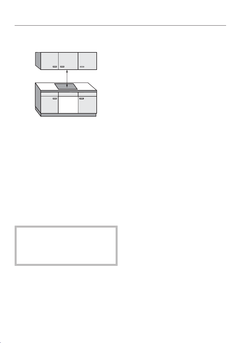
Damage from falling objects.
Take care not to damage the cooktop when fitting wall units or a rangehood
above it.
Fit the wall units and the rangehood before the cooktop.
The veneer or laminate coatings of worktops (or adjacent kitchen
units) must be treated with 100°C heat-resistant adhesive which will
not dissolve or distort. Any splashbacks must be of heat-resistant
material.
The cooktop must not be installed over a fridge, fridge-freezer,
freezer, dishwasher, washing machine, washer-dryer or tumble dryer.
A gas cooktop must not be installed directly next to a deep fat
fryer as the gas flames could ignite the fat in the fryer. It is essential
to maintain a distance of at least 300mm between these two
appliances.
When installing the cooktop, make sure that the gas hose and
electrical connection cable cannot come into contact with hot
appliance parts.
The electrical cable and any flexible gas connection pipes must be
installed in such a way so that they do not come into contact with
any moving kitchen parts (e.g. a drawer), and cannot become
trapped.
This cooktop is not suitable for installation and operation with
aftermarket lids or covers fitted.
This appliance must not be installed and operated in mobile
installations (e.g. on a ship).
Carefully observe the safety clearances listed on the following
pages.
All dimensions in this instruction booklet are given in mm.
4
Page 5
Safety distance above the cooktop
A minimum safety distance must be
maintained between the cooktop and
the rangehood above it. See the
rangehood manufacturer's operating
and installation instructions for details.
If the manufacturer's instructions are
not available for the rangehood, a
minimum safety distance as per AS/
NZS 5601.1 must be maintained.
Safety distances
For any flammable objects, e.g. utensil
rails, wall units etc., a minimum safety
distance of 600mm must be
maintained between these objects and
the highest part of the cooktop below.
When two or more appliances which
have different safety distances are
installed together below a
rangehood, you should observe the
greatest safety distance.
5
Page 6
Safety distances
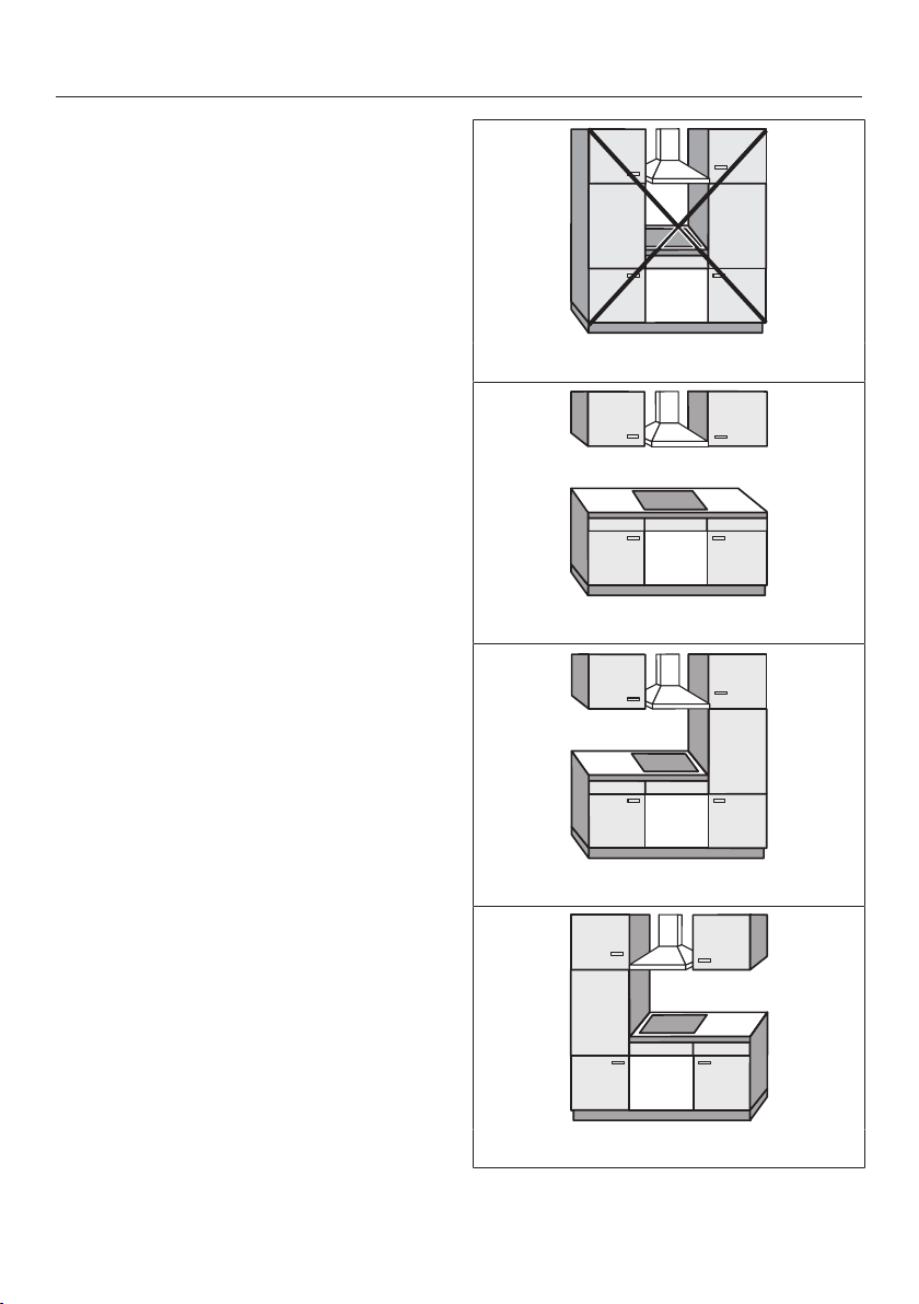
Safety distances to the sides and back of the appliance
Ideally the appliance should be installed
with plenty of space on either side.
There may be a wall at the rear and a
tall unit or wall on one side (right or left).
On the other side, however, no tall unit
or wall should stand higher than the
appliance. Before installing the
appliance, check that the location
provides the required clearances from
combustible material and, if necessary,
provide protection to adjacent surfaces
as required by regulations.
Not allowed
Recommended
Not recommended
Not recommended
6
Page 7
Safety distances
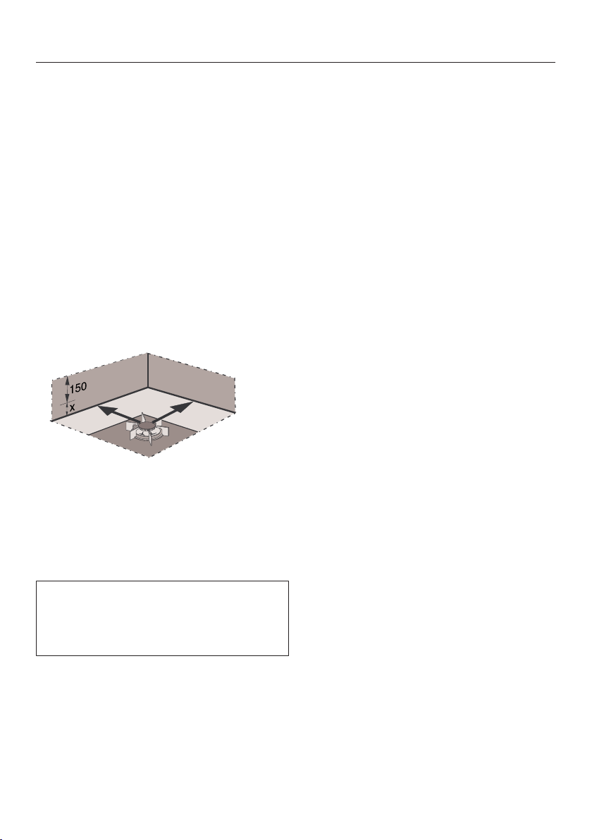
A gas appliance shall be installed such
that the surface temperature of any
nearby combustible surface* will not
exceed 65°C above ambient.
The minimum clearance from a
combustible surface shall be a 200mm
horizontal distance from the periphery
of any gas burner (AS/NZS 5601.1).
If that horizontal clearance is less than
200mm, that vertical surface must be
protected by a non-combustible
material for 150mm above the top of
the edge of the nearest burner for the
full dimension of the cooktop (depth,
width).
X Height from worktop surface to the
top of the edge of the burner
Clearance underneath the appliance
A minimum safety clearance of 30mm
must be provided underneath the
appliance.
Please note that clearance must also be
provided for the installation of the
flexible gas connection hose and mains
electrical cable if the appliance is to be
installed above a closed surface (e.g.
an oven).
The shown area indicates the protected
surface, which may be ceramic tiles or
other approved material.
*Combustible surface:
A material which will ignite and burn,
and includes material which has been
flameproofed.
7
Page 8
Installation notes
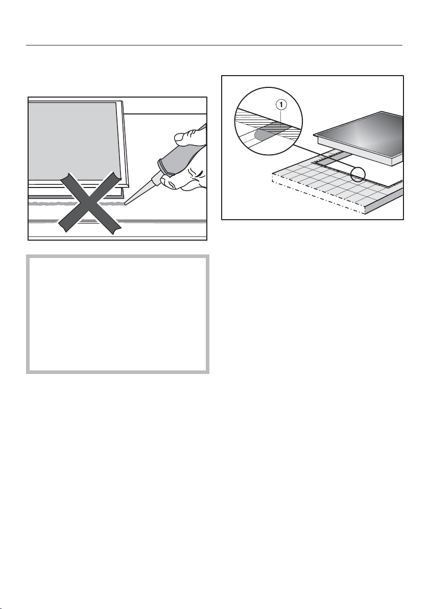
Seal between the cooktop and the worktop
Do not use sealant between the
cooktop and the worktop. This could
result in damage to the cooktop or
the worktop if the cooktop ever
needs to be removed for servicing.
The sealing strip under the edge of
the top part of the appliance
provides a sufficient seal for the
worktop.
Tiled worktop
Grout lines and the hatched area
underneath the cooktop frame must be
smooth and even. If they are not, the
cooktop will not sit flush with the
worktop and the sealing strip
underneath the cooktop will not provide
a good seal between the cooktop and
the worktop.
8
Page 9
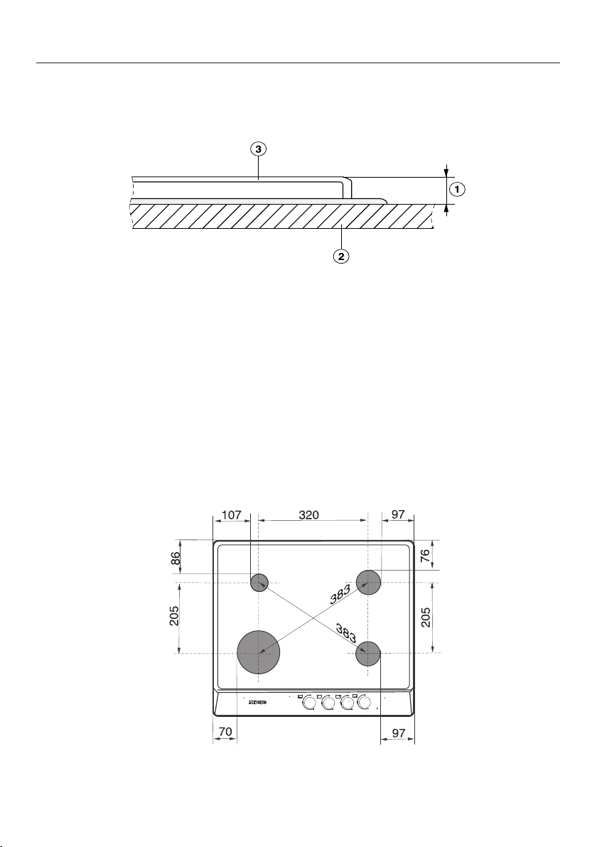
Detailed dimensions
Height of pan supports above the worktop surface
a
Vertical distance
b
Worktop surface
c
Pan support
The vertical distance from the top of the pan supports to the surface of the
worktop is 48mm.
Distances from burner to the edge of the appliance
KM 362-1
9
Page 10
*INSTALLATION*
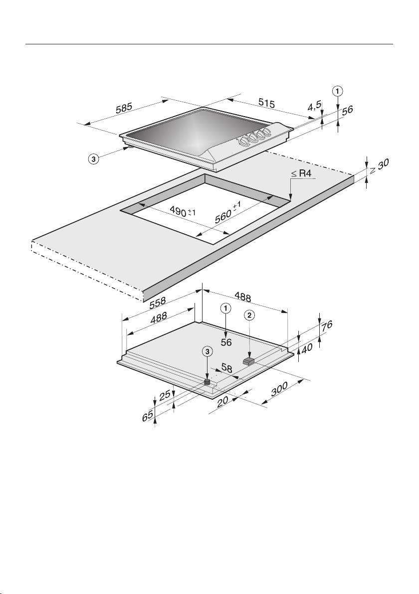
Installation dimensions
KM 360 / KM 362
a
Building-in depth
b
Mains connection box
c
Gas connection R½ - ISO7-1
10
Page 11

*INSTALLATION*
KM 360-1 / KM 362-1
Installation dimensions
a
Building-in depth
b
Mains connection box
c
Gas connection R½ - ISO7-1
11
Page 12
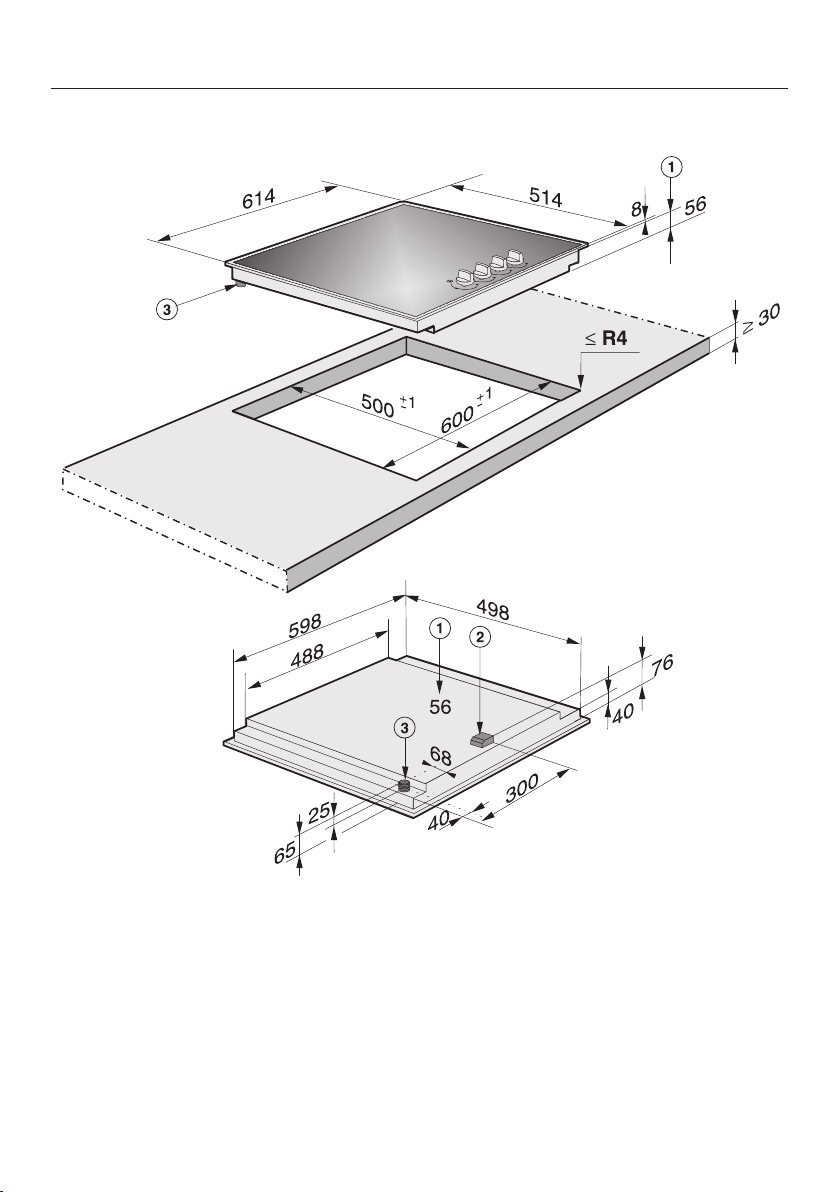
*INSTALLATION*
Installation dimensions
KM 361 G / KM 363 G
a
Building-in depth
b
Mains connection box
c
Gas connection R½ - ISO7-1
12
Page 13
*INSTALLATION*
Installation
Preparing the worktop
Create the worktop cut-out as shown
in “Building-in dimensions”.
Remember to maintain the minimum
safety distances (see “Safety
distances”).
Seal the cut surfaces with a suitable
heat-resistant sealant to avoid
swelling caused by moisture. The
sealant must be temperatureresistant.
Make sure the sealant does not
come into contact with the top
surface of the worktop.
The sealing strip ensures that the
cooktop will sit securely in the cut-out
without slipping. Any gap between the
frame and worktop will become
smaller over time.
Installing the cooktop
Feed the mains connection cable
down through the worktop cut-out.
Place the cooktop centrally in the
cut-out. When doing this make sure
that the seal of the appliance sits
flush with the worktop on all sides.
This is important to ensure an
effective seal all round.
If the seal does not meet the worktop
correctly on the corners, the corner
radii (≤R4) can be carefully scribed to
suit.
Do not use any additional sealant
(e.g. silicone).
Connect the cooktop to the mains
electricity supply.
Connect the cooktop to the gas
supply (see “Gas connection”).
13
Page 14

*INSTALLATION*
Installation
Securing the cooktop
Secure the cooktop using the
brackets supplied.
Checking operation
After installing the cooktop, ignite all
burners to check that they are
operating correctly:
– The flame must not go out on the
lowest setting, or when the control is
turned quickly from the highest to the
lowest setting.
– On the highest setting, the flame
must have a distinctive and visible
core.
14
Page 15

*INSTALLATION*
Electrical connection
All electrical work must be carried out
by a suitably qualified and competent
person in strict accordance with current
local and national safety regulations.
Connection must be made via a
switched socket. This will make it easier
for service technicians should the
appliance need to be repaired. The
electrical socket must be easily
accessible after installation.
Danger of injury!
Miele cannot be held liable for
unauthorised installation,
maintenance and repair work as this
can be dangerous to users.
Miele cannot be held liable for
damage or injury caused by incorrect
installation, maintenance or repair
work, or by an inadequate or faulty
earthing system (e.g. electric shock).
If the plug has been removed or the
connection cable is not supplied with
a plug, the cooktop must be
connected to the mains supply by a
suitably qualified electrician.
If the appliance is to be hard-wired,
an additional means of
disconnection must be provided for
all poles in accordance with the
wiring rules. When switched off,
there must be an all-pole contact
gap of at least 3mm in the switch
(including switch, fuses and relays).
Connection data is shown on the
data plate. It must match the mains
electrical supply.
After installation, ensure that all
electrical components are shielded
and cannot be accessed by users.
Connection
AC 230 V, 50 Hz
The voltage and rated load are given on
the data plate. Please ensure these
match the household mains supply.
Residual current device
For extra safety, it is advisable to
protect the appliance with a suitable
residual current device (RCD) with a trip
range of 30 mA.
Replacing the mains connection cable
Risk of electric shock!
Incorrect connection to the electricity
supply may result in an electric
shock.
The mains connection cable must
only be replaced by a suitably
qualified and competent electrician
in accordance with current local and
national safety regulations.
If the mains cable needs to be replaced,
it must be replaced with a special
connection cable, type H05VV-F (PVC
insulated), available from Miele, by a
Miele authorised service technician or
suitably qualified and competent
electrician in order to avoid a hazard.
The connection data is given on the
data plate.
15
Page 16

Gas connection
Risk of explosion due to an
incorrect gas connection.
If the gas connection is carried out
incorrectly, it may result in gas
leakage.
Connection to the gas supply must
only be undertaken by an authorised
and registered gas installer in strict
accordance with current local and
national safety and building
regulations. The installer is
responsible for ensuring that the
appliance functions correctly when
installed.
Risk of explosion due to an
incorrect conversion.
If the conversion to another type of
gas is carried out incorrectly, it may
result in gas leakage.
Conversion from one type of gas to
another must only be undertaken by
an approved and registered gas
installer in strict accordance with
current local and national safety and
building regulations. The installer is
responsible for ensuring that the
appliance functions correctly when
installed.
The gas connection must be
installed so that connection can be
made either from inside or outside
the kitchen furniture unit. Every
appliance must have its own
isolating valve. The isolating valve
must be easily accessible and visible
(by opening the cabinet door if
necessary).
Check with your local gas supplier
about the type of gas supplied and
compare this information with the
type of gas quoted on the
appliance's data plate.
The cooktop is not connected to an
exhaust flue.
When installing and connecting the
appliance, please observe the
relevant regulations and ensure it has
adequate ventilation once installed.
The gas connection must be made in
accordance with national and local
regulations.
Special provisions of the local gas
supplier as well as building
regulations must also be observed.
Risk of heat damage.
Gas connections, gas hoses or pipes
and mains connection cables can be
damaged if exposed to heat from the
cooktop.
After installation make sure that
neither the gas hose/pipe nor the
mains cable can come into contact
with hot parts of the appliance and
that the gas hose/pipe and
connections on the cooktop cannot
come into contact with hot exhaust
fumes.
16
Page 17

Gas connection
Risk of explosion due to
damaged gas hoses and pipes.
Gas can leak from damaged flexible
gas hoses.
Attach flexible gas hoses in such a
way that the hose assembly is not
exposed to high temperatures
exceeding the maximum
recommended by the hose
manufacturer, subjected to strain,
kinking, permanent deformation or
damage by vermin.
Connect the cooktop to the gas
supply in accordance with national
and local regulations. Check the gas
connection for any leaks.
The gas pressure must be set by an
approved gas fitter and a full
operational test and a test for
possible leakages must be carried
out by the gas fitter after installation.
Depending on country of destination,
this appliance is set up for connection
to natural gas or ULPG. See adhesive
label on the appliance:
– G = NG (natural gas)
– LP = ULPG (Propane/Butane)
Depending on country of destination,
jets are supplied for conversion to a
different type of gas. If the appropriate
jets have not been supplied with the
appliance, you will need to contact
Miele. Conversion to another type of
gas is described in the section
“Conversion to another type of gas”.
Connecting the cooktop
The cooktop is supplied with a ¹/₂"
threaded gas connection. There are two
connection options:
– Fixed connection.
– Flexible hose class B or D which
complies with AS/NZS1869 and
must be certified. The minimum inner
diameter(Ø) must be 10mm and the
maximum length 1200mm.
Risk of explosion due to gas
leakage.
Unsuitable sealant will not ensure the
required leak protection for
connections.
Ensure that a suitable sealant is
used.
17
Page 18

Gas connection
a
b
~ 60
a
Setting the gas pressure
The gas pressure must be set by the
authorised gas fitter as shown on the
data plate:
Natural gas 1.0 kPa
ULPG (Propane/Butane) 2.75 kPa
The gas pressure must be set with the
largest burner operating at maximum
setting.
For ULPG models
For natural gas models
The gas regulator is only included with
appliances which are set up for
connection to natural gas. The
regulator must be connected directly
to the appliance.
a
Pressure Test Point
Loosen the screw in the test point
until it is free in its housing. The
screw is retained in this position.
a
Connection R¹/₂" with test point
b
Connection R¹/₂" with test point and
90° angle
When using a 90° angle the buildingin depth will increase to the depth of
the elbow used.
18
Connect the hose from the pressure
gauge.
Reassemble one of the large burners,
turn on the gas and manually light the
burners.
Disconnect the hose from the
pressure gauge and screw in the test
point screw.
For natural gas models: Connect the
gas regulator directly to the
appliance.
Page 19

Burner ratings
Nominal ratings for KM 360 / KM 360-1 / KM 361
Burner Gas type Highest setting Lowest setting
MJ/h MJ/h
Auxiliary burner NG
ULPG
Normal burner NG
ULPG
Fast burner NG
ULPG
Total NG
ULPG
3.85
3.60
5.85
6.35
10.35
9.68
25.90
25.98
0.70
0.41
1.10
0.97
1.70
1.65
Nominal ratings for KM 362 / KM 362-1
Burner Gas type Highest setting Lowest setting
MJ/h MJ/h
Auxiliary burner NG
ULPG
Normal burner NG
ULPG
Wok burner NG
ULPG
Total NG
ULPG
3.85
3.60
5.85
6.35
14.40
14.40
29.95
30.70
0.70
0.41
1.10
0.97
5.74
5.58
19
Page 20

Burner ratings
Nominal ratings for KM 363
Burner Gas type Highest setting Lowest setting
MJ/h MJ/h
Auxiliary burner NG
ULPG
Normal burner NG
ULPG
Fast burner NG
ULPG
Total NG
ULPG
3.85
3.60
5.85
6.35
10.35
9.68
20.05
19.63
0.70
0.41
1.10
0.97
1.70
1.65
20
Page 21

*INSTALLATION*
Conversion to another type of gas
Risk of explosion due to an
incorrect conversion.
If the conversion to another type of
gas is carried out incorrectly, it may
result in gas leakage.
Conversion from one type of gas to
another must only be undertaken by
an authorised and registered gas
installer in strict accordance with
current local and national safety and
building regulations. The installer is
responsible for ensuring that the
appliance functions correctly when
installed. Disconnect the cooktop
from the electricity supply and turn
off the gas supply.
Jet table
The jet markings refer to a ¹/₁₀₀mm
bore diameter.
Burner
Main jet Small jet
Natural gas
Auxiliary 0.90 0.42
Normal 1.10 0.52
Fast 1.50 0.60
Wok burner 1.70/0.70 1.30 (1A)
ULPG
Auxiliary 0.52 0.23
Normal 0.70 0.32
Fast 0.87 0.40
Wok burner 1.00/0.37 0.68
When converting to another type of
gas, both the main and small jets
need to be changed.
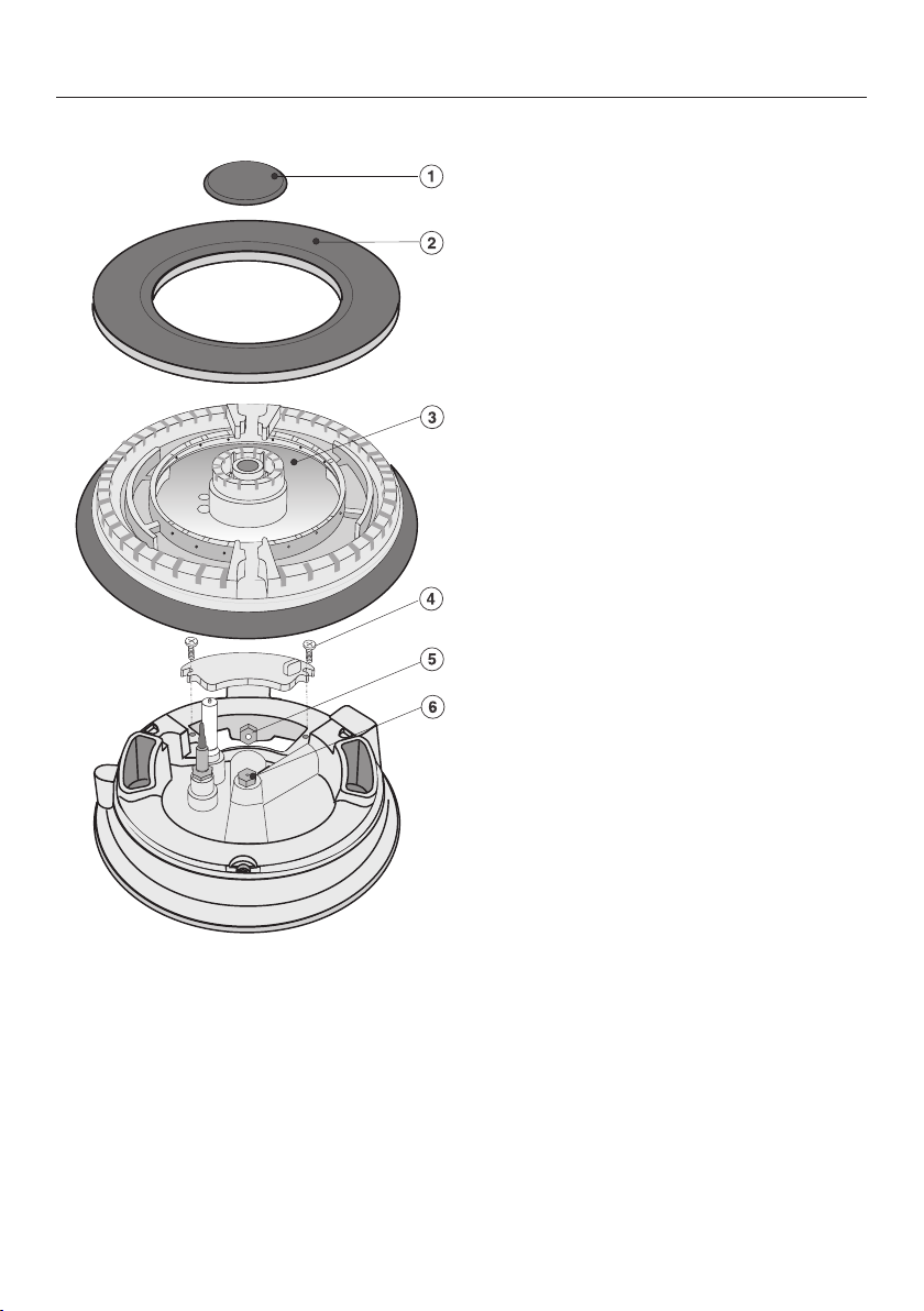
Changing the main jets
Auxiliary, normal and fast burners
Remove the pan support, burner
cap and burner head.
Using an M7 socket spanner,
unscrew the main jet.
Fit the correct jets securely (see jet
table).
Secure the jets against inadvertent
loosening with sealing wax.
Changing the jets
Disconnect the cooktop from the
electricity supply and turn off the gas
supply.
21
Page 22
*INSTALLATION*
Conversion to another type of gas
Wok burner
Fit the correct jets securely (see jet
table).
Secure the jets against inadvertent
loosening with sealing wax.
Remove the burner cap, burner
ring and burner head.
Undo the screws and remove the
cover plate.
Using a socket spanner or flat
spanner (M7), unscrew the main
jets(larger diameter) and
(smaller diameter).
22
Page 23
*INSTALLATION*
a
b
Changing the small jets
To change the jets, the burner fixing
screws must first be loosened and the
upper section of the appliance
removed.
Pull the control knobs off.
Remove the burner components.
Lift the top of the appliance off.
To lift out the stainless steel upper
section, lift it at the rear, slide
forwards and take it out.
To remove the ceramic upper
section, insert the supplied tool at the
corner between the appliance frame
and the worktop, lift it up and take it
out.
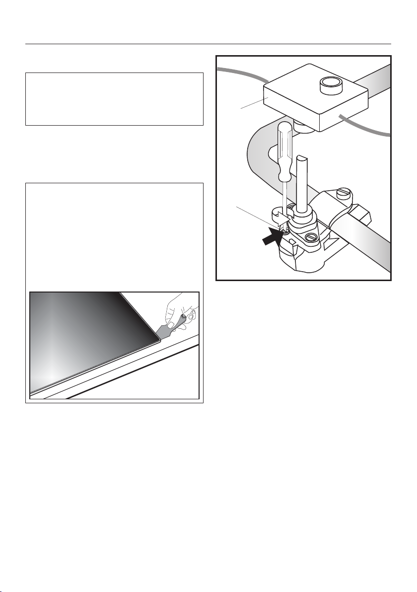
Conversion to another type of gas
Remove the ignition switch.
Using a small screwdriver, unscrew
the small jet in the gas fitting.
Pull out the jet with a pair of pliers.
Fit the correct jets securely (see jet
table).
Secure the jets against inadvertent
loosening with sealing wax.
23
Page 24
*INSTALLATION*
a
b
Conversion to another type of gas
Checking operation
Check all gas fittings for leaks.
Reassemble the cooktop.
Ignite all burners to check that they
are operating correctly.
– The flame must not go out on the
lowest setting, or when the control is
turned quickly from the highest to the
lowest setting.
– On the highest setting, the flame
must have a distinctive and visible
core.
Adhere the label supplied with the
jets over the old label stating the type
of gas being used.
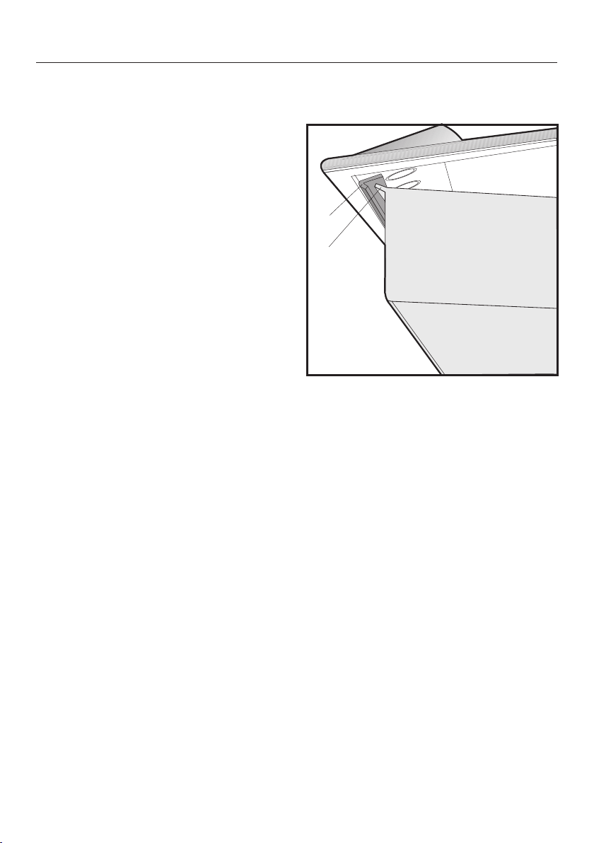
Refitting the stainless steel upper section
Position the upper section as shown
in the illustration.
Push it forwards first and then
backwards until the angle bracket
clicks into place underneath the
lip.
Then lower the upper section.
24
Page 25

Service
Contact in case of fault
In the event of any faults which you cannot remedy yourself, please contact Miele.
Contact information for Miele can be found at the end of this booklet.
Please quote the model and serial number of your appliance when contacting
Miele. This information can be found on the data plate.
Data plate
Adhere the extra data plate supplied with the appliance in the space below. Make
sure that the model number matches the one specified on the back cover of these
operating and installation instructions.
Warranty
The manufacturer's warranty for this appliance is 2years.
For further information, please refer to your warranty booklet.
25
Page 26

Page 27

Miele Experience Centre and
Head Office Melbourne:
1 Gilbert Park Drive
Knoxfield, VIC 3180
Miele Experience Centre South Melbourne:
206-210 Coventry Street
South Melbourne, VIC 3205
Miele Experience Centre and Office Sydney:
3 Skyline Place
Frenchs Forest, NSW 2086
Miele Experience Centre and Office Brisbane:
Tenancy 4C, 63 Skyring Terrace
Newstead, QLD 4006
Miele Experience Centre and Office Perth:
83-85 Sir Donald Bradman Drive
Hilton, SA 5033
Miele Experience Centre and Office Adelaide:
Miele Australia Pty. Ltd. Miele New Zealand Limited
Level 2, 10 College Hill
Freemans Bay, Auckland 1011
Miele Experience Centre
Auckland:
8 College Hill
Freemans Bay, Auckland 1011
Miele Global Headquarters
Germany
Miele & Cie. KG
Carl-Miele-Straße 29
33332 Gütersloh
Federal Republic of Germany
Head Office:
IRD 98 463 631
ACN 005 635 398
ABN 96 005 635 398
Miele Experience Centre Gold Coast:
131 Ferry Road
Southport, QLD 4215
Miele Experience Centre
Wellington:
183 Featherston Street
Wellington 6011
0800 464 353 (0800 4 MIELE)
www.miele.co.nz
205-207 Stirling Highway
Claremont, WA 6010
1300 464 353 (1300 4 MIELE)
www.miele.com.au
Page 28

KM360 / KM360-1 KM / KM361 / KM362 / KM362-1 /
KM363
M.-Nr. 05 827 671 / 05en-AU, NZ
 Loading...