

Installation instructions
Gas hob
KM 320 G
It is essential to read these
operating instructions before
installing or using the machine,
to avoid the risk of accidents
or damage to the machine. M.-Nr. 05 591 610
\

2

Contents
Contents
Warning and Safety instructions . . . . . . . . . . . . . . . . . . . . . . . . . . . . . . . . . . . . . 4
Building in . . . . . . . . . . . . . . . . . . . . . . . . . . . . . . . . . . . . . . . . . . . . . . . . . . . . . . . . 4
Safety distance above appliances . . . . . . . . . . . . . . . . . . . . . . . . . . . . . . . . . . . 5
Appliance dimensions and worktop cut-out . . . . . . . . . . . . . . . . . . . . . . . . . . . . 6
Installation . . . . . . . . . . . . . . . . . . . . . . . . . . . . . . . . . . . . . . . . . . . . . . . . . . . . . . . 7
Building in . . . . . . . . . . . . . . . . . . . . . . . . . . . . . . . . . . . . . . . . . . . . . . . . . . . . . . . . 7
Fixing the support brackets . . . . . . . . . . . . . . . . . . . . . . . . . . . . . . . . . . . . . . . . . . . 7
General . . . . . . . . . . . . . . . . . . . . . . . . . . . . . . . . . . . . . . . . . . . . . . . . . . . . . . . . . . 8
Electrical connection . . . . . . . . . . . . . . . . . . . . . . . . . . . . . . . . . . . . . . . . . . . . . . 9
Gas connection . . . . . . . . . . . . . . . . . . . . . . . . . . . . . . . . . . . . . . . . . . . . . . . . . . 11
Natural gas / liquid gas . . . . . . . . . . . . . . . . . . . . . . . . . . . . . . . . . . . . . . . . . . . . . 12
Conversion to another type of gas. . . . . . . . . . . . . . . . . . . . . . . . . . . . . . . . . . . 13
Jet table . . . . . . . . . . . . . . . . . . . . . . . . . . . . . . . . . . . . . . . . . . . . . . . . . . . . . . . . . 13
Changing the jets. . . . . . . . . . . . . . . . . . . . . . . . . . . . . . . . . . . . . . . . . . . . . . . . . . 14
After conversion . . . . . . . . . . . . . . . . . . . . . . . . . . . . . . . . . . . . . . . . . . . . . . . . . . . 15
3
Warning and Safety instructions
Warning and Safety instructions
Building in
Fit wall units, cooker hood and adjacent units before fitting the gas
hob, to avoid damaging the hob.
The room in which the gas hob is
installed must be at least 20 m
size with a door or window in it which
can be opened to the outside air.
The veneer or laminate coatings of
worktops (or adjacent kitchen
units) must be treated with 100°C heatresistant adhesive which will not dissolve or distort.
Any backmoulds must be of
heat-resistant material.
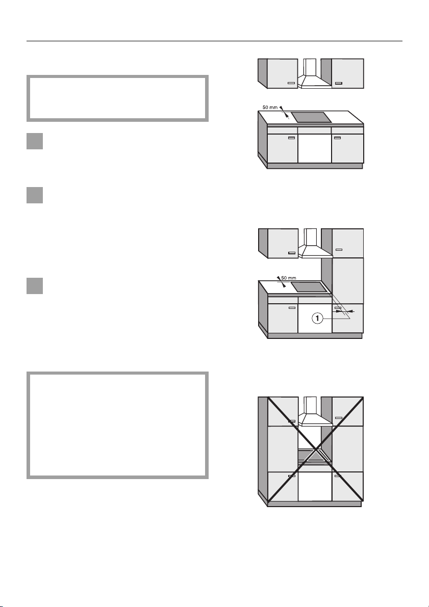
Ideally the hob should be installed
with plenty of space on either side.
There may be a wall at the rear and
wall or tall units at one side. On the
other side however, no unit or divider
should stand higher than the hob.
A safety distance b of 150 mm
must be maintained between the
KM 320 G and adjacent furniture,
e.g. a tall unit, because of the heat
given off by the flames, and to allow
fumes to dissipate. There must be a
minimum safety distance of 50 mm
between the hob and a back wall.
3
in
Fig. 1
recommended
Fig. 2
not recommended
Fig. 3
not allowed
4
Warning and Safety instructions
A gas hob must not be installed
next to an electric fryer, as the gas
flames could ignite the fat in the fryer.
It is essential to maintain a distance of
at least 300 mm between these two appliances.
This hob must not be installed over
a dishwasher, washing machine,
tumble dryer, refrigerator or freezer.
The high temperatures radiated by the
hob could damage the appliance
below.
This equipment is not designed for
maritime use or for use in mobile installations such as caravans, aircraft
etc. However it may be suitable for
such usage subject to a risk assessment of the installation being carried
out by a suitably qualified engineer.
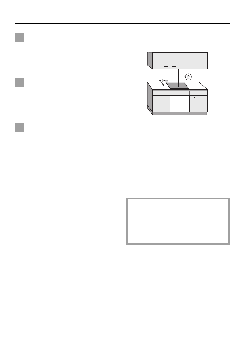
Safety distance above appliances
Fig. 4
A minimum safety distance
maintained between the hob and the
cooker hood above it. See the manufacturer’s operating and installation instructions for details. For any flammable objects, e.g. utensil rails, wall units etc. a
minimum safety distance of at least 760
mm should be maintained between it
and the hob below.
must be
c
When two or more appliances are installed together below a cooker
hood, which have different safety
distances given in their installation
instructions you should select the
greater distance of the two.
All dimensions in this instruction
booklet are given in mm.
Keep these instructions in a safe place
and pass them on to any future owner
of the appliance.
5

Appliance dimensions and worktop cut-out
Appliance dimensions and worktop cut-out
KM 320 G
Building in height
c
Fig. 5
Support bracket
b
Make a cut-out in the worktop following the dimensions given in Fig. 5.
There must be a minimum safety distance of 50 mm between the hob
and the back wall and 150 mm distance from a side wall to the right or
left of the hob. (See "Warning and
Safety instructions").
Seal the cut surfaces with a suitable
sealant to avoid swelling caused by
moisture. The materials used must
be heat resistant.
6
If, when building in, the seal of the
frame does not sit flush with the
worktop surface at the corners, use
a suitable too to achieve the required radius (max.R4).

Installation
Building in
e
d
Fig. 6
Remove the protective foil e from
the sealing strip supplied
stick it on the underside of the hob
as shown in Fig. 6.
Place the hob in the prepared cutout.
d
and
Installation
Fixing the support brackets
30-50
b
Fig. 7
Secure the gas hob in position with
fixing brackets
shown in Figs. 5 and 7.
supplied as
b
Feed the electrical connection cable
through the cut-out and connect.
Make the gas connection (see relevant section).
7

General
General
Important
Under no circumstances should
sealant find its way between the
frame of the top part of the hob and
the worktop.
This could cause difficulties if the
hob ever needs to be taken out for
servicing, (possibly leading to damage to the frame and worktop).
The sealing strip under the edge of the
top part of the hob provides a sufficient
seal for the worktop.
Fig. 8
8

Electrical connection
Electrical connection
All electrical work should be carried
out by a suitably qualified and competent person in strict accordance
with national and local safety regulations.
Installation, repairs and other work
by unqualified persons could be
dangerous. The manufacturer cannot be held responsible for unauthorised work.
Ensure power is not supplied to the
appliance while installation or repair
work is being carried out.
The appliance must only be operated when built-in. This is to ensure
that all electrical parts are shielded.
Live parts must not be exposed.
Do not connect the appliance to the
mains electricity supply by an extension lead. These do not guarantee
the required safety of the appliance.
If the socket is not accessible after installation (depending on country) an additional means of disconnection must
be provided for all poles.
For extra safety it is advisable to install
a residual current device (RCD) with a
trip current of 30 mA (in accordance
with DIN VDE 0664, VDE 0100 Section
739).
When switched off there must be an all-
pole contact gap of 3 mm in the isolator switch (including switch, fuses and
relays according to EN 60 335).
Important U.K.
This appliance is supplied for connection to a single phase 230-240 V 50 Hz
supply with a 3-core cable.
The wires in the mains lead are coloured in accordance with the following
code:
Green/yellow = earth
Blue = neutral
The voltage, rated load and fusing are
given on the data plate. Ensure that
these match the household mains supply.
Connection of this appliance should be
made via a suitable isolator (rated load
above 3 kW) or a double pole fused
spur connection unit or fused plug and
switched socket (rated load up to 3
kW) which complies with national and
local safety regulations and the on/off
switch should be easily accessible
after the appliance has been built in.
Brown = live
As the colours of the wires in the mains
lead of this appliance may not correspond with the coloured markings
identifying the terminals in your plug,
proceed as follows:
9

Electrical connection
The wire which is coloured green and
yellow must be connected to the terminal in the plug which is marked with the
letter E or by the earth symbol z or coloured green or green and yellow.
The wire which is coloured blue must
be connected to the terminal which is
marked with the letter N or coloured
black.
The wire which is coloured brown must
be connected to the terminal which is
marked with the letter L (GB /IRL) or A
(AUS / NZ) or coloured red.
WARNING
THIS APPLIANCE MUST BE
EARTHED
Important
The electrical safety of this appliance
can only be guaranteed when continuity is complete between the appliance and an effective earthing system, which complies with local and
national regulations. It is most important that this basic safety requirement is
tested by a qualified electrican. The
manufacturer cannot be held responsible for the consequences of an inadequate earthing system such as an electric shock.
Non-rewireable plugs (BS 1363)
If this appliance is fitted with a nonrewireable plug, the following information applies:
If the socket outlets are not suitable for
the plug supplied with this product, it
must be cut off and an appropriate
plug fitted.
The fuse carrier and the fuse should be
removed from the old plug and disposed of. The plug cut from the flexible
cord should then be disposed of and
on no account be inserted into any
socket elsewhere in the house (electric
shock hazard).
The fuse cover must be re-fitted when
changing the fuse, and if the fuse
cover is lost, the plug must not be used
until a suitable replacement is obtained. The colour of the correct replacement cover is that of the coloured
insert in the base of the plug, or the colour that is embossed in words in the
base of the plug (as applicable to the
design of the plug fitted).
The correct fuse rating of the replacement fuses that are ASTA approved to
BS 1362 should be fitted. Replacement
fuse covers may be purchased from
your local electrical supplier, or Miele
Service agent.
10
The manufacturer can assume no
responsibility for damage which is
the direct or indirect result of incorrect installation or connection.

Gas connection
Connection to the gas supply, or
conversion from one type of gas to
another should only be undertaken
by an approved and registered gas
installer in strict accordance with
local and national safety regulations, (e.g. Corgi registered in the
U.K). Every appliance should have
its own isolating valve.
Gas connection
Connection
Conversion to another type of gas is described under the relevant Section.
The gas connection must be installed
so that connection can be made either
from inside or outside the kitchen unit,
and the isolating valve must be easily
accessible and visible (by opening one
of the kitchen unit doors, if necessary).
Check with your local gas supplier
about the type of gas, and compare
this information with the type of gas
quoted on the hob data plate.
The installer is responsible for ensuring that the appliance functions correctly.
The gas hob is normally suitable for
connection to either natural or liquid
gas. Check suitability in your country
with your dealer or agent.
GB and IE II 2 H 3+
20 mbar, 28-30/37 mbar
The hob is supplied ready for connection to natural gas.
A set of jets for conversion to liquid gas
is included with the hob.
A test for possible leakages must be
carried out after installation.
The relevant building regulations must
also be observed.
11

Gas connection
Fig. 9
Natural gas / liquid gas
An appropriate rigid or flexible connection and isolating valve must be
installed for final connection.
The gas connection must be so sited
that it is not adversely heated when
the appliance is in operation.
In particular ensure that hot gas exhaust cannot touch the gas hose
or appliance connections.
After installing the appliance the
gas burners have to be set for local
conditions.
When the gas hob has been installed it is essential to check that
neither the gas hose nor the electricity cable is in contact with hot
parts of the appliance or hot gas exhaust, otherwise heat damage to
the hose and cable could occur.
12

Conversion to another type of gas
KM 320 G
Conversion to another type of gas
Jet table
When converting to liquid gas, the
main jets and the small jets of all
burners must be changed.
Nominal rating for all gas types with
the burner full on
Gas type kW
Normal
burner
Fast
burner
Nominal rating at low setting
Normal
burner
Fast
burner
Natural H
Liquid
Natural H
Liquid
Gas type kW
Natural H
Liquid
Natural H
Liquid
1.75
1.75 / 127 g/h
3.00
3.00 / 219 g/h
0.30
0.35
0,50
0.50
Main
jet
Ø
Natural gas
Normal burner
Fast burner
Liquid gas
Normal burner
Fast burner
The jet markings refer to 1/100 mm of
the jet diameter.
Contact your local gas supplier if the
natural gas connection pressure is less
than 18 mbar or higher than 25 mbar.
1.00
1.29
0.65
0.85
Low
setting
jet
Ø
0.42
0.54
0.27
0.36
Screw in the new jets according to the
following table.
13

Conversion to another type of gas
Changing the jets
Disconnect the gas hob from the
electricity supply by switching off at
the socket and withdrawing the
plug or by removing the mains fuse.
Changing the main jets
Changing the small jets
Fig. 11
Guide a screwdriver through the
holes in the the lower casing of the
hob and loosen the small jets
Pull the jets out with a pair of pointed
pliers.
Put in the new jets with a pair of
pointed pliers.
g
.
Fig. 10
Take off the pan support, the burner
cover
Using an (M7) socket spanner unscrew the main jet
Change the main jet.
Reassemble the burner head and
burner cover in the correct order.
14
and the burner head e.
c
.
f
Secure the new jets with a screwdriver.
Finally secure the jets against inadvertent loosening with sealing wax.

Conversion to another type of gas
After conversion
Stick the label supplied with the jets
over the sticker which states the type
of gas.
Check that the gas hob is sealed.
Finally turn the gas on and check the
flame characteristics.
Ignite the flame.
The flame must not go out in the
lowest setting or when the control is
turned quickly from a high to a low setting.
In the highest setting the flame must
have a distinctive and visible core.
15

Alteration rights reserved 01/1401
This paper consists of cellulose which has been bleached without the use of chlorine
 Loading...