

Page 1

Operating Instructions
Industrial cleaner
IR 6001
To prevent accidents
and machine damage
read these instructions
before
installation or use.
UV
M.-Nr. 06 006 651
Page 2

Contents
Guide to the machine. . . . . . . . . . . . . . . . . . . . . . . . . . . . . . . . . . . . . . . . . . . . . . . 4
IMPORTANT SAFETY INSTRUCTIONS. . . . . . . . . . . . . . . . . . . . . . . . . . . . . . . . . 6
Functional description . . . . . . . . . . . . . . . . . . . . . . . . . . . . . . . . . . . . . . . . . . . . 10
Cleaning process. . . . . . . . . . . . . . . . . . . . . . . . . . . . . . . . . . . . . . . . . . . . . . . . . . 10
Water recycling. . . . . . . . . . . . . . . . . . . . . . . . . . . . . . . . . . . . . . . . . . . . . . . . . 10
MCU-control. . . . . . . . . . . . . . . . . . . . . . . . . . . . . . . . . . . . . . . . . . . . . . . . . . . . . . 11
First Use . . . . . . . . . . . . . . . . . . . . . . . . . . . . . . . . . . . . . . . . . . . . . . . . . . . . . . . . 12
Setting the water softener . . . . . . . . . . . . . . . . . . . . . . . . . . . . . . . . . . . . . . . . . . . 12
Loading and unloading . . . . . . . . . . . . . . . . . . . . . . . . . . . . . . . . . . . . . . . . . . . . . 12
Adding detergent. . . . . . . . . . . . . . . . . . . . . . . . . . . . . . . . . . . . . . . . . . . . . . . . . . 14
Level indicator . . . . . . . . . . . . . . . . . . . . . . . . . . . . . . . . . . . . . . . . . . . . . . . . . . . . 15
Venting the dispensing systems . . . . . . . . . . . . . . . . . . . . . . . . . . . . . . . . . . . . . . 16
Altering the temperature and drying times . . . . . . . . . . . . . . . . . . . . . . . . . . . . . . 16
Key switch . . . . . . . . . . . . . . . . . . . . . . . . . . . . . . . . . . . . . . . . . . . . . . . . . . . . . . . 18
Turning on . . . . . . . . . . . . . . . . . . . . . . . . . . . . . . . . . . . . . . . . . . . . . . . . . . . . . . . 19
Program cycle . . . . . . . . . . . . . . . . . . . . . . . . . . . . . . . . . . . . . . . . . . . . . . . . . . . . 20
Interrupting a program. . . . . . . . . . . . . . . . . . . . . . . . . . . . . . . . . . . . . . . . . . . . . . 21
Turning off . . . . . . . . . . . . . . . . . . . . . . . . . . . . . . . . . . . . . . . . . . . . . . . . . . . . . . . 21
Applications . . . . . . . . . . . . . . . . . . . . . . . . . . . . . . . . . . . . . . . . . . . . . . . . . . . . . 22
Optimizing the standard programs . . . . . . . . . . . . . . . . . . . . . . . . . . . . . . . . . . . . 22
Dosage and Detergents . . . . . . . . . . . . . . . . . . . . . . . . . . . . . . . . . . . . . . . . . . . . 24
Wash tests . . . . . . . . . . . . . . . . . . . . . . . . . . . . . . . . . . . . . . . . . . . . . . . . . . . . . . . 24
Electronics . . . . . . . . . . . . . . . . . . . . . . . . . . . . . . . . . . . . . . . . . . . . . . . . . . . . . . . 25
Cleaning metal. . . . . . . . . . . . . . . . . . . . . . . . . . . . . . . . . . . . . . . . . . . . . . . . . . . . 28
Optics . . . . . . . . . . . . . . . . . . . . . . . . . . . . . . . . . . . . . . . . . . . . . . . . . . . . . . . . . . 30
Baskets and Inserts . . . . . . . . . . . . . . . . . . . . . . . . . . . . . . . . . . . . . . . . . . . . . 30
Particle decontamination . . . . . . . . . . . . . . . . . . . . . . . . . . . . . . . . . . . . . . . . . . . . 32
Reactivating the water softener . . . . . . . . . . . . . . . . . . . . . . . . . . . . . . . . . . . . . 33
Filling the salt container . . . . . . . . . . . . . . . . . . . . . . . . . . . . . . . . . . . . . . . . . . . . . 34
Position the salt container as follows . . . . . . . . . . . . . . . . . . . . . . . . . . . . . . . . . . . 35
Serial interfaces . . . . . . . . . . . . . . . . . . . . . . . . . . . . . . . . . . . . . . . . . . . . . . . . . . 36
Preparing the MCU for report printout . . . . . . . . . . . . . . . . . . . . . . . . . . . . . . . . . . 37
2
Page 3

Contents
Cleaning and Care . . . . . . . . . . . . . . . . . . . . . . . . . . . . . . . . . . . . . . . . . . . . . . . . 39
Cleaning the filters in the wash cabinet. . . . . . . . . . . . . . . . . . . . . . . . . . . . . . . . . 39
Cleaning the coarse filter. . . . . . . . . . . . . . . . . . . . . . . . . . . . . . . . . . . . . . . . . . . . 39
Cleaning the fine filter . . . . . . . . . . . . . . . . . . . . . . . . . . . . . . . . . . . . . . . . . . . . . . 39
Cleaning the flat and micro-fine filters . . . . . . . . . . . . . . . . . . . . . . . . . . . . . . . . . . 40
Cleaning the water inlet filters. . . . . . . . . . . . . . . . . . . . . . . . . . . . . . . . . . . . . . . . . 41
Drying unit (TA) - Cleaning and care . . . . . . . . . . . . . . . . . . . . . . . . . . . . . . . . . 42
Changing the coarse filter . . . . . . . . . . . . . . . . . . . . . . . . . . . . . . . . . . . . . . . . . . . 42
Exchanging the HEPA particle filter . . . . . . . . . . . . . . . . . . . . . . . . . . . . . . . . . . . . 42
Correcting minor faults . . . . . . . . . . . . . . . . . . . . . . . . . . . . . . . . . . . . . . . . . . . . 43
Heater limiter . . . . . . . . . . . . . . . . . . . . . . . . . . . . . . . . . . . . . . . . . . . . . . . . . . . . . 43
Installation . . . . . . . . . . . . . . . . . . . . . . . . . . . . . . . . . . . . . . . . . . . . . . . . . . . . . . 44
Electrical connection. . . . . . . . . . . . . . . . . . . . . . . . . . . . . . . . . . . . . . . . . . . . . . 45
Plumbing. . . . . . . . . . . . . . . . . . . . . . . . . . . . . . . . . . . . . . . . . . . . . . . . . . . . . . . . 46
Caring for the environment . . . . . . . . . . . . . . . . . . . . . . . . . . . . . . . . . . . . . . . . . 48
Disposal of an old appliance . . . . . . . . . . . . . . . . . . . . . . . . . . . . . . . . . . . . . . . . . 48
3
Page 4
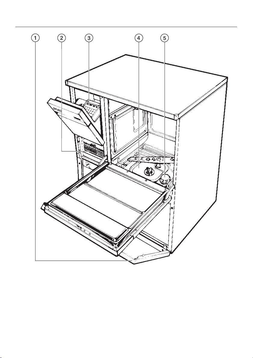
Guide to the machine
a Service panel
b TA Drying unit
4
c MCU
d Filter combination
e Reactivation socket for salt container
(water softener)
Page 5
Guide to the machine
f Main power switch
g Key switch
h Display
l "On-Off" indicator light
l "In Operation" indicator light
m "Fault-Error" indicator light
i Operating control panel
j Serial interface
n "DOS dispenser level" indicator light
o Door release
5
Page 6

IMPORTANT SAFETY INSTRUCTIONS
Please pay attention to the following
This machine conforms to current
safety requirements. Inappropirate
use can however lead to personal
injury and property damage. When
using an electrical appliance, basic
precautions should always be
followed including the following:
Keep these instructions in a safe
place, and make them available to
future users.
Use
This machine is designed for
commercial use and for
specialized applications only, as
described in these Operating
Instructions. Using it for purposes other
than those for which it is designed
could cause damage or injury. The
manufacturer cannot be held
responsible for any damage caused by
improper use.
The installation of this unit in non
stationary locations (e.g. ships)
must be performed by a qualified
installer or service agency, in strict
accordance with national and local
safety regulations and standards.
notes, to maintain safe procedures.
The machine should be
commissioned and then
maintained only by a Miele authorized
service technician. Repairs by
unqualified persons could be
dangerous.
Do not install the machine in an
area where a danger of explosion
may be present.
Be certain this appliance is
properly installed and grounded by
an authorized technician. To guarantee
the electrical safety of this appliance,
continuity must exist between the
appliance and an effective grounding
system. It is imperative that this basic
safety requirement be met. If there is
any doubt, have the electrical system of
the house checked by a qualified
technician. The manufacturer cannot be
held responsible for the consequences
of an inadequate grounding system
(e.g. electric shock).
A damaged machine can be
dangerous. Turn off the power
immediately and call an authorized
Miele Service technician.
Unauthorized personnel should not
be allowed access to the machine
or its controls.
6
Page 7

IMPORTANT SAFETY INSTRUCTIONS
Take care when handling liquids
such as detergents, neutralizing
agents, wetting agents and rinse aids.
These may contain irritant or corrosive
ingredients, acids or alkalis. Never use
any organic solvent, as the danger of
an explosion exists. Follow all safety
instructions! Wear protective gloves
and goggles.
Avoid inhalation of powder
cleaners.
The water in the machine must not
be used as drinking water.
Do not sit or lean on the open door
or rest objects on it. This could
cause the machine to tip and be
damaged or cause an injury.
Be careful when sorting items with
sharp pointed ends. Position them
in the machine so that you do not hurt
yourself or create danger for other
operators.
When using this machine regard
the high temperatures and be
especially careful not to scald or burn
yourself. When opening the door
bypassing the electrical lock, a danger
of burning, scalding or corrosion exists
or when using disinfection agents, the
inhalation of toxic fumes. Let baskets
and inserts cool before touching them.
Any water which may remain in
containers will be very hot and must be
emptied into the wash cabinet.
After drying with the TA drying unit
open the door to allow the items
and inserts to cool down.
Do not touch the heating elements
during or directly after the end of a
program. You could burn yourself.
Never use a hose or steam cleaner
on or near the machine.
Before any maintenance or repair
work is undertaken, the machine
must be unplugged or disconnected
from the main power supply or circuit
breaker.
The following points should be
observed to avoid damage to the IR
6001 and the loads being cleaned.
Use only cleaning agents
formulated for special processes
and approved by Miele for use with this
machine. Use of unsuitable cleaning
agents could adversely affect the load
or the machine.
Pre-treating (e.g. with cleaning
agents) certain soiling can cause
foam. Foam can have an adverse effect
on the cleaning results.
7
Page 8

IMPORTANT SAFETY INSTRUCTIONS
When a chemical additive is
recommended, the manufacturer of
the machine takes no responsibility for
the effect of the chemical on the
material of the items being cleaned.
Please be aware of changes in
formulation, storage conditions,
concentration etc, which may not be
publicized by the chemical producer,
can have a negative effect on the
cleaning result.
When using cleaning agents and
specialized products it is essential
that the manufacturer’s instructions are
followed. Only use the detergent for the
application described by the
manufacturer, to avoid any material
damage or the occurrence of strong
chemical reactions.
The machine is designed for
operation with water and cleaning
agents only. Organic solvents must not
be used in the machine, as the danger
of explosion exists under certain
circumstances. Although this is not the
case with all organic solvents, other
problems could arise with their use, for
example damage to rubber and
synthetic materials of the machine.
In critical applications where
stringent requirements have to be
met, it is strongly recommended that all
process parameters, such as cleaning
agent or quality of water are discussed
with the Miele Applications specialists.
If the clean objects are subject to
particularly stringent requirements
(e.g. chemical analysis, industrial
process), a regular quality control test
should be carried out by the user to
ensure that required standards of
cleanliness are being achieved.
The mobile units and special
inserts should only be used for
their specific application.
Empty any containers or utensils
before arranging them in the
machine.
Do not allow any remains of acids
or solvents, in particular
hydrochloric acid or chloride solutions,
as well as corroding ferrous material to
get into the wash cabinet. The
presence of compounds in any solvents
should be minimal, (especially those in
hazard class A1).
Do not wash items with chips
adhered. Depending on kind and
shape of the chips the circulation pump
can get damaged or contact corrosion
can occur.
8
Page 9

IMPORTANT SAFETY INSTRUCTIONS
Ensure that solutions or steam
containing hydrochloric acid do not
come in contact with the stainless steel
casing of the machine, to avoid any
corrosion damage.
Waste water must be discharged in
accordance with national and local
water regulations. Consult your local
water authority. Where discharge is
indirect, ensure that waterborne
residues do not exceed statutory limits.
Please follow the advice on
installation in these instructions
and the separate Installation Instruction
manual.
Using accessories
Only specific additional equipment
made by Miele should be
connected to this machine. Consult
Miele on the type and application of
such equipment.
Disposal of an old appliance
When disposing of your old
machine make it unusable.
Disconnect the power cord and cut off
the plug. For environmental and safety
reasons ensure the machine is
completely drained of any residual
water and cleaning agent. Observe
safety regulations and wear safety
goggles and gloves. Make the door
lock inoperative, so that children cannot
accidentally shut themselves in.
Machines with a tank system, remove
the water from the tank before
disposing the machine.
The manufacturer cannot be held
responsible for damage caused by
non-compliance with these
Important Safety Instructions.
9
Page 10

Functional description
Applications
The Industrial Cleaner is designed for
specialized sectors of industrial high
technology production, where a
consistently high standard of cleaning
is required, and where the structure of
the items to be cleaned may be
complex. Areas of appliacation are:
Electronics, such as circuit boards
–
and solder frames,
Metal cleaning
–
Optics
–
– Particle decontamination
Cleaning process
The Industrial Cleaner works on the
principle of fresh water circulation. The
bath time for cleaning and rinsing is
approx. 20-30 minutes. Drying is
effected by means of an integrated
drying unit. A period of 15 to 45
minutes must be added to the above
time to thoroughly dry the batch,
depending on the heat retention
capacity of the items in the load and
the amount of water remaining. The
machine can be programmed, and a
variety of baskets and inserts used,
depending on specific needs. Special
cleaning programs can be written for
individual applications.
Water recycling
The IR 6001 comes equipped with a
two stage drainage system and a pump
to bring rinse water back into the
machine enabling it to be re-used.
Rinse water which is still quite clean, for
example from the final rinse, can be
directed into an external holding tank
and be fed back into the machine for
the following pre-wash or main wash
cycle. The holding tank does not come
with the machine, and must be
supplied on-site.
The following procedures can be
realized with the Industrial Cleaner and
an external holding tank.
1. Without an external holding tank
The water from the pre-wash and main
wash is discharged into the waste
water system, or into an effluent
treatment plant.
2. Recycling of rinse water
E.g. the water of the last two rinse
cycles will be re-used for the rinse or
neutralization for the next batch. The
waste water of the cleaning cycle will
be drained into the waste water system
or an effluent treatment plant.
3. Recycling of cleaning waste water
The waste water of the cleaning cycle
will be re-used for the cleaning cycle of
the next batch. The waste water of the
remaining rinse cycles will be drained
into the waste water system or an
effluent treatment plant.
10
Page 11

MCU-control
The Industrial Cleaner is equipped with
a micro computer unit control (MCU).
The control is programmable, giving the
user the ability to optimize programs
and create new cleaning programs.
The controls can be programmed for a
range of individual applications; for
example, time, temperature, water
quality, dispensing of various liquid
detergents and additives. During the
wash process the display will chow
either the current stage of the process,
or an error message if there is a fault.
The large memory capacity enables
different programs to be stored and
then selected according to the load to
be cleaned. Different keys are used
with the key switch to restrict access to
the operating and programming
options. The control unit has two serial
interfaces which allow wash parameters
to be monitored or documented
through the use of a printer or PC (not
supplied).
Functional description
Should your needs change or the
machine be needed for other
applications, different programs can be
designed with the help of Miele.
11
Page 12

First Use
Setting the water softener
Before using the machine for the first
time the regeneration parameters must
be set by the service technician
according to the local water hardness
level (see MCU operating and
programming manual). The local water
authority can advise you of the water
hardness in your area.
Loading and unloading
Press the door release button, hold
^
the door grip and open the door at
the same time.
Load the items into their respective
^
baskets and inserts.
Automatic coupling
The machine is supplied as standard
with an automatic spring-loaded
coupling for either the upper basket or
a mobile unit.
Make sure that the spring adapter
for water connection engages
correctly when a basket or injector
unit is inserted in the machine. It
must be 3/16" (4-5 mm) higher than
the water connection inlet in the
machine. If this is not the case,
adjust the adapter.
^ Loosen the lock ring.
12
^
Push up the adapter (3/16" [4-5 mm]
higher than the water connection inlet
in the machine) and re-tighten the
lock ring.
^
Select baskets and inserts
depending on the items to wash
Page 13
First Use
Exchanging the upper spray arm
When the lower basket is being used
alone for large items such as solder
frames, the large spray arm, supplied
with the machine, should be attached
to the water inlet on the roof of the
cabinet.
Pull out the top basket, lift it from the
^
runners and remove.
Unscrew the small upper spray arm
^
retainer and remove.
Install the large upper spray arm with
^
its threaded spindle flange.
Important: Please note that only top
baskets, mobile units or injector
nozzle should be coupled without a
spray arm. For other applications the
small spray arm should be
re-installed.
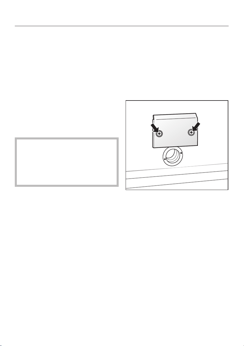
Drying air deflector
The machine comes equipped with a
deflector for the heated air in front of
the vent at the rear of the wash cabinet.
The deflector must be dismantled if
mobile units or baskets with a TA
adapter (an adapter at the drying air
vent in the wash cabinet) are used.
^ Loosen both screws at the deflector.
^
Remove the deflector.
13
Page 14
First Use
Adding detergent
Exercise caution when handling
,
detergents! They may contain acids,
alkalis or disinfectants.
Take care to ensure that the
necessary safety precautions are
observed. Wear protective gloves
and goggles.
The IR 6001 comes standard with 3
DOS pumps for automatic dispensing
of liquid additives: 3 DOS 60/30 injector
pumps for dispensing liquid cleaning
agent. Dispensing capacity is 60 ml/30
second (channel 6, 8 and 9).
The amounts of cleaning agent
required, depending on the application
chosen for this machine, are dispensed
through these systems.
Additionally a DOS pump DOS 10/30
for dispensing acid additives is
supplied. Dispensing capacity is
10 ml/30 secs (channel 9).
If needed, the Miele Technical Service
can exchange a DOS 60/30 with the
DOS 10/30.
,
Powdered detergent must be
placed on the door (regard
manufacturer’s dosage). Use wash
programs without draining at the
start of a program. Caution: Avoid
powder inhalation!
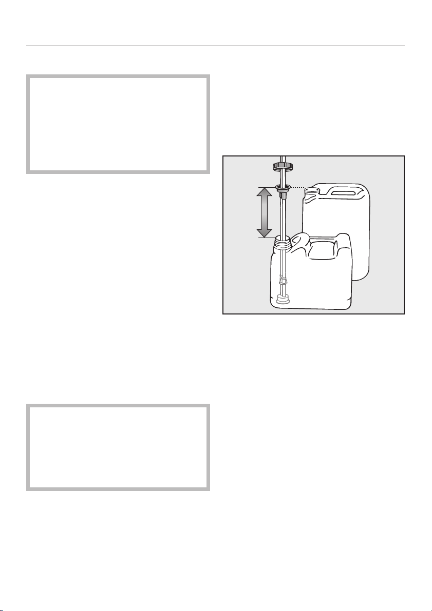
Filling the containers with liquid
additive
The IR 6001 has 3 suction tubes for use
with the external detergent containers.
Select the stopper with the appropriate
thread (depending on the size of the
container).
The suction tube length can be
adjusted.
^ Insert the suction tube all the way
until its end touches the bottom of the
container.
^
Screw the cap on firmly.
14
Page 15
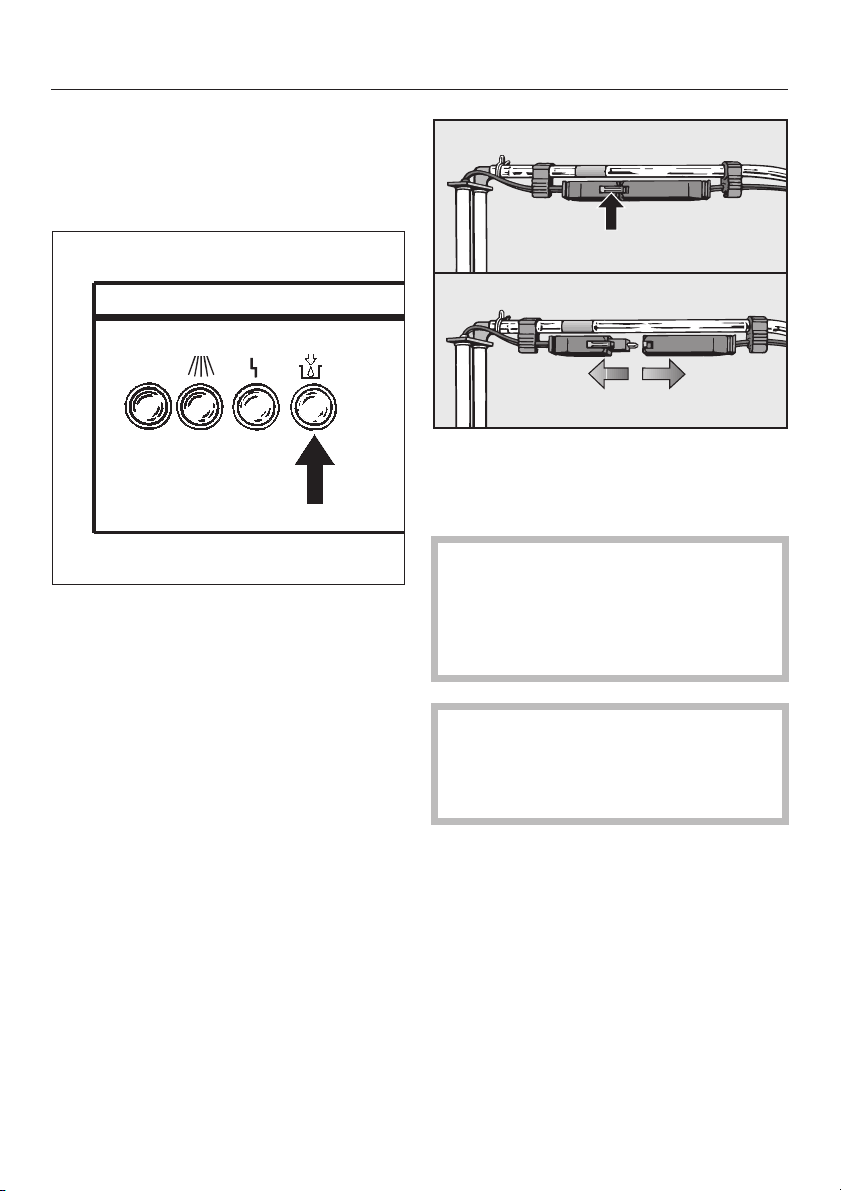
Level indicator
The DOS level indicator v lights if at
least one of the containers fitted with a
suction tube is almost empty.
I-O
The indicator also lights if at least one
suction tube is inserted in an empty
container, that is not used.
First Use
Press the unlock latch and pull the
^
plug connection apart.
The containers should not be
allowed to empty completely and
should be filled regularly, otherwise
the first wash cycle, after refilling,
will take place without detergent.
If a dispensing system is not used, the
service technician should remove the
plug connection for this system, to
prevent the DOS indicator light from
staying on.
The internal dispenser pump hoses
are subject to wear and should be
replaced as preventative
maintenance every 12 to 18 months.
15
Page 16

First Use
Venting the dispensing
systems
Before using the machine for the first
time, the air must be expelled from the
dispensing system.
This should also be done if the
container has not been refilled in time
and the dispensing system was allowed
to empty completely.
Close the door.
^
Set the key switch to position II.
^
Turn the main switch to I (On).
^
^ Select program 14
(DOS-FILL/DOS-FUELL) using the
key pads O or M. "14 DOS FILL" (or
DOS-FUELL) appears in the display
field.
^ Press the "Start" key pad.
^ Repeat the program several times if
necessary.
Altering the temperature and
drying times
The temperatures for cleaning and
drying, as well as drying times, are
stored for each program (see program
summary supplied).
Note: Header parameters which
have not been programmed do not
appear in the display.
To change the stored values:
Set the key switch to position II.
^
^ Turn the main switch to I (On).
^ Select the program (see "Turning
on").
16
Page 17

First Use
Altering temperature T1, from 201°F
to 185 °F (94 °C to 85 °C) (example)
Touch pad
P XXX T1 094
U XXX T1 094
O XXX T1 093
O XXX T1 092
O XXX T1 085
S XXX T1 085
S XXX PROGRAMNAME
_ = number flashes
Display
XXX PROGRAMNAME
Altering the T2 temperature
Start by pressing the touch pad P
twice, the proceed as for temperature
T1. Note: Header parameters which
have not been programmed do not
appear in the display.
Altering the TA drying temperature,
from 194 °F to 176 °F (90 °C to 80 °C)
(example)
Touch pad
P XXX T1 094
P XXX T2 070
P XXX TA 090
U XXX TA 090
N XXX TA 090
Display
XXX PROGRAMNAME
XXX = program number selected
O XXX TA 08
S XXX TA 080
S XXX PROGRAMNAME
_ = number flashes
XXX = program number selected
0
17
Page 18

First Use
Altering ZA drying time from 30 min
to 40 min (example)
Touch pad
P XXX T1 094
P XXX T2 070
P XXX TA 090
P XXX ZA 030
U XXX ZA 031
M XXX ZA 031
M XXX ZA 032
Display
XXX PROGRAMNAME
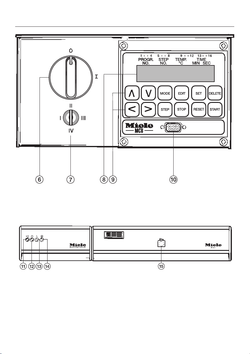
Key switch
The following choices can be selected
with the four position key switch, using
the three keys provided:
l = Starting a fixed program or all
released programs
II = Program selection and program
start of all programs, altering of head
parameters
III = Program selection and program
start of all programs, altering of head
parameters,
programing,
accessing system parameters
IV = Program selection and program
start of all programs, altering of head
parameters,
programing,
accessing system parameters,
accessing the service mode
M XXX ZA 040
S XXX ZA 040
S XXX PROGRAMNAME
_ = number flashes
XXX = program number selected
18
Page 19

First Use
The slot in the key hole (A) points to the
switch position selected (B).
A
B
Three keys are supplied, numbered
separately 1, 2 and 3:
Key 1 for swich settings I, II
Key 2 for swich settings I, II, III
Key 3 for swich settings I, II, III, IV
Turning on
1. 1. Free program selection
Set the key switch to position II.
^
Turn the main switch to I (On).
^
Select the program with the keys O
^
or M.
1 WAFER-CHIP Wafer chip
2 HALBLEITER Semiconductors
3 LOETRAHMEN Solder frames
4 LEI-KOL PCB Rosin
5 LEI-WASSER PCB Water
6 METALL Metal
7 LEI-OEL PCB Oil
10 FUELLEN Fill
11 ENTLEEREN Empty
12 GROBFILTER *) Prefilter TA *)
13 FEINFILTER *) S-filter TA *)
14 DOS-FUELL DOS- Fill
15 REGENERIER Regenerate
*) Only visible when using switch
setting III or IV.
For detailed information on the
programs see the supplied program
summary.
The respective program is displayed.
^
Press the "Start" key pad.
If the selected program is desired as a
fixed program, it can be stored:
^
Turn the key switch to position I.
The key can then be withdrawn.
19
Page 20

First Use
2. 2. Starting a fixed program
Set the key switch to position I.
^
Turn the main switch to I (On).
^
The pre-selected program appears in
the display field.
Press the "Start" key pad.
^
The in operation light l comes on to
show that the machine is running a
program.
Note: If several programs are
required as fixed programs, (i.e.
switchable with key setting I),
consult the programming manual
under PROG-SELECTION.
The program parameters (codetext)
can be read off the display without
activating any further functions:
00 6 0 0 3 0 0 7 8 1 5 1 0
Program cycle
After starting, the program proceeds
automatically. It is finished when the in
operation light l goes out.
The y Fault-Error indicator light
will come on if the system has been
interrupted during operation. The cause
of the interruption is shown in the
display field as an error message. The
following error messages are possible:
ERR DOOR
The door has been opened during the
wash program.
Call the Miele Technical Service
Department.
ERR INFLOW
Water intake has been impeded (closed
valve, clogged filters, etc.)
ERR DRAIN
Water is not draining freely (kinked
hose, sewer blockage, etc.)
12 34
1. Program number
2. Current program step
3. Current temperature
4. Remaining step time in minutes and
seconds
Touch the MODE pad to see the current
program segment, (pre-wash, main
wash, interim rinse, final rinse, drying or
the Codetext).
20
ERR TEMP
Temperature is not reached in
prescribed time. Call Miele Technical
Service Dept.
ERR T-SENSOR
Defective sensor.
Call the Miele Technical Service
Department.
ERR PUMP-PRG
Programming fault: several pumps were
activated simultaneously in one
program step.
ERR KEY
Defective key switch.
Call the Miele Technical Service
Department.
Page 21

First Use
ERR WATER-PRG
Programming fault: more than one
water inlet valve has been activated in
one program step, or an inlet valve has
not been activated in combination with
the circulation pump.
ERR WATERINF
Water inflow time is insufficient.
Program ADD-WATER or if already
programmed increase the ADD-WATER
parameters.
ERR BATTERY
Change the lithium battery within 4
weeks after this message.
^ If possible, reset the fault and start
the program again.
When the following operating
messages appear in the display, the
appropriate action must be taken:
GROBFILTER (PREFILTER)
Change the coarse filter in the drying
unit (see page on drying unit
maintenance). Then reset the filter
display message.
Interrupting a program
Once a program has been started, it
should only be interrupted in an
emergency or if the items are moving
about noisily due to incorrect loading.
The machine must be turned off, the
water drained from the wash cabinet
and the program re-started.
Turn the main switch to 0 (Off).
^
Wait 5 seconds, then turn the main
^
switch to I (On).
DRAIN is displayed if there is water in
^
the machine (the water is then
pumped away).
^ OR the program parameters are
displayed with a flashing step time
(no water in the machine).
^ Set the key switch to position II.
^ Press the "Reset" key pad.
^ Open the door and arrange the items
properly.
^
Close the door.
^
Set the key switch to setting III or IV.
^
Use touch pad Oor M to select
program 12 GROBFILTER (Coarse
filter).
^
Press the "Start" key pad.
FEINFILTER (HEPA-Filter)
Call the Miele Technical Service Dept to
change the particle filter in the TA
drying unit. (See page on drying unit
maintenance.)
REGENERIEREN (REGENERATE)
Replenish the water softener with salt.
(see Reactivating water softener).
^
Start the programme again.
Turning off
On completion of the program the ON
indicator light l goes out. If the
machine is not to be used again:
^
Turn the main switch to 0 (Off). This
disconnects the machine from the
main power supply.
^
Turn off the water valves.
21
Page 22

Applications
Optimizing the standard
programs
Standard programs are stored in the
MCU control for various applications
(see program chart). These programs
cannot be changed with the exception
of the head parameters (T1, T2, TA und
ZA). The dosage is programmable.
Although the dosage time is set to
00:00, a detergent will be dosed if a
time is set under
SERVICEMODE/DOSINGPUMPS.
Alternatively a step time > 00:00
may be programmed.
Using the standard programs mostly a
process optimization and a respective
program change is necessary. If
different wash programs are used
alternately (e.g. LEI-KOL [PCB water]
and LOETRAHMEN [Solder frames],
alternately liquid and powder detergent
may be used.
The programs are set without recycling
of waste water (process type 1). If rinse
water or the cleaning agent should be
re-used, corresponding program
changes must be made.
Therefore a standard program should
be copied to a free program location
and adjust it accordingly.
22
Page 23

Applications
Applications example
One example for two applications,
which are washed in a Industrial
Cleaner, is the cleaning of circuit
boards and solder frames in the IR
6001 with a soiling of resin flux. Liquid
detergent is used for circuit boards and
powdered detergent for solder frames.
1. Circuit boards
Copy program 004 (LEI-KOL) [PCB
^
Rosin] to a free program space (e.g.
program 400).
^ Program the dosage by step time
(step with D1R). If two cleaning
agents are used program additionally
the dosage of the second detergent
(step with D3N).
^ Establish process parameters (e.g.
wash temperature T1, Drying
temperature TA and Drying time ZA)
by optimizing tests and program
accordingly.
^
Store the program changes.
2. Solder frames
Copy program 003 (LOETRAHMEN)
^
[Solder frames] to a free program
space (e.g. program 300).
Delete step "Drain".
^
Delete program step with D1R, where
^
a liquid detergent is used, because a
powdered detergent will be used.
A neutralization with citric acid
^
respective with a phosphatic agent is
allowed for treatment of solder
frames in the program 003 (step with
D3N). Because D1R and D3N are
used for solder frames, D3N must be
reprogrammed to D4C (channel 8):
8). Furthermore the DOS 10/30 for the
acid neutralizing agent must be
installed by a Miele Service
Technician and connected to channel
8. When programming the dosage
time, regard the performance of the
DOS 10/30.
^ Establish process parameters by
optimizing tests and program them
accordingly.
^
Store the program changes.
23
Page 24

Applications
Dosage and Detergents
Alkaline, neutral and acid processed
chemicals are used to clean different
materials. The standard pumps DOS
60/30 are for alkaline products (e.g.
cleaning agents) and under some
circumstances also usable for pH
neutral products (e.g. tensid containing
cleaning intensifier). The flow rate is 60
ml in 30 secs resp. 120 ml in 60 secs
and depends on the tenacity of the
liquid product.
The DOS 10/30 is usable for acid
products (e.g. neutralization agent).
The flow rate is 10 ml in 30 secs resp.
20 ml in 60 secs and depends on the
tenacity of the liquid product.
When programming the dosage, be
certain that the liquid agent to be
dosed is pumped with the respective
pump.
Wash tests
In many cases a cleaning problem was
wash technically resolved before the IR
6001 was purchased. Additional
applications may result when using the
Industrial cleaner, e.g. to increase the
capacity. Many customers do their own
wash tests. A change in the application
causes a need for an adjustment of the
wash program, specially of the
detergents, of the soiling and material
of the items to be washed.
As an aid the following pages contain
tables with information regarding
material, soiling and the respective
wash program and detergent to be
used.
If you have any questions, call the
Miele application specialist.
24
Page 25

Electronics
Populated circuit boards and solder
frames require cleaning that takes into
account product specifications and the
soldering processes used.
Circuit boards
Circuit boards can be cleaned of resin
residues in the machine. The results
depend on the type of flux used. For
individual application, Miele
recommends consultation with cleaning
technology advisors. Cleaning is
generally performed with tenside
additives (0.5 - 0.7% at 149 °F - 167 °F
(65 °C - 75 °C)). The wash/rinse
process consists of several stages and
purified ion-free water is used
throughout (DI-water).
For surface mount or hybrid technology,
the use of water soluble soft solder
paste is recommended. A high
standard of cleaning can then be
achieved by using water and variable
temperature washes.
Applications
Top basket O 500-10
The time for a cleaning program is
approx. 30 minutes for the wash phase
and 40 - 50 minutes for the drying
phase, depending on the structural
complexity and volume of the load.
Baskets designed for circuit boards are
made of plastic coated stainless steel.
These are the O 500-10 top basket and
U 500-10 bottom basket, which
together can hold 73 PCBs.
Bottom basket U 500-10
Large numbers of small circuit boards
can be washed in inserts like E 402, E
403 with E 439-10. Fix lightweight,
sensitive circuit boards with the cover
nets A 2.
25
Page 26

Applications
Solder frames
Depending on the type of soil, an
alkaline cleaning agent at a low
concentration of 0.3 - 0.5%, a
neutralization agent or wetting agent
(0.1%), is used.
With aluminum solder frames, using
de-ionized water (either throughout or
in the final rinse, depending on quality
standard required) reduces the risk of
damage to the material, which may be
adversely affected by non-purified
water after prolonged use.
Example: 8 solder frames (L 18 11/16"
x W 16 29/32" x D 2") (L 475 mm x W
430 mm x S 45-50 mm) can be cleaned
and dried in the machine within 30
minutes if operated with a hot water
intake of 149 °F (65 °C).
Sample configuration
Lower basket U 874 with E 500 insert.
Insert E 500
26
Page 27

Applications
Application,
Material/
Soiling
Program P 004
Wash temperature
T1 (°C)
Wash temperature
T2 (°C)
Cleaning agent
Concentration2)for
use
Neutralizer
Concentration
for use
Note a second
1) Characteristics of cleaning and neutralizing agents are given, not product names.
2) Concentration for use = percentage of the chemical additive in the wash water solution
Water requirement / wash cycle = approximately 15 liters, e.g.:
0.1 % = 0.5 fl.oz. (15 ml) or 15 g amount to be dispensed
0.3 % = 1.6 fl.oz. (45 ml) or 45 g amount to be dispensed
0.5 % = 2.6 fl.oz. (75 ml) or 75 g amount to be dispensed
0.7 % = 3.7 fl.oz. (105 ml) or 105 g amount to be dispensed
1)
Circuit boards
flux with resin
LEI-KOL
(PCB Rosin)
65 - 75 65 - 75 75
65 65 - 75 65 - 75 65 - 75
1)
neutral,
with tensides
0.5 - 0.7 %
2)
cleaning agent
may be
necessary
Circuit boards
water soluble flux
P 005
LEI-WASSER
(PCB water)
where foam occurs
use silicon-free
anti-foaming agent
Solder frames
flux with resin
P 003
LOETRAHMEN
(Solder frames)
(3 - 10 min)
alkaline,
with silica
0.5 %
anti-foam additive
required
slightly acidic, citric
or phosphoric acid
base
0.1 - 0.15 %
Do not use neutralizers if suscepticle steel
items are cleaned on the frames (Delete
Step 11) and set T2 to 65 °C.
Solder frames
water soluble flux
P 003
LOETRAHMEN
(Solder frames)
65 - 75
alkaline,
with silica
0.5 %
anti-foam additive
not always required
slightly acidic, citric
or phosphoric acid
base
0.1 - 0.15 %
27
Page 28

Applications
Cleaning metal
The machine can be used for cleaning
products requiring degreasing, removal
of dust or polishing/grinding paste, or
pre-treatment before painting or
galvanizing.
Cleaning agents and wash parameters
can be selected according to the
properties of the iron, steel or
non-ferrous metal. A test wash is
advisable with polishing/grinding
pastes to identify the most suitable
cleaning processes.
A final rinse with de-ionized water is
often necessary, especially with
non-ferrous metals, to achieve the
cleaning result required.
,Make sure that no file dust or
other fillings, (from drilling, milling
etc), especially from iron based
materials, are introduced into the
machine.
The upper basket O 188-10 and lower
basket U 874-10 are recommended as
a basic basket set for the machine or
for small items the insert E 439-10 with
four wash levels. To intake the different
substrate, various filter bowls and
inserts can be used. These filter bowls
and inserts are inserted in the baskets
O 188-10/U 874-10 or
E 439-10.
28
Page 29

Applications
Application,
Material/
Soiling
Program P 006 METAL or
Wash
temperature T1
(°C)
Wash
temperature T2
(°C)
Cleaning agent
Concentration
for use
Neutralizer
Concentration
for use
Note If a neutralizer is needed, select P 006, delete Step 5 (P 006),
Stainless steel
oil, grease,
particles etc.
P 007 LEI-OEL
(PCB oil)
65 - 75
(2 - 10 min)
65 - 75 50 - 65 50 - 60 40 - 50
1)
mildly alkaline, to
2)
highly alkaline
0.3 - 0.5 %
1)
not always
necessary to
neutralize with a
phosporic acid
product when using
alkaline cleaner
2)
0.1 - 0.15 %
and add a Step (Channel 9 and 14) between Steps 11 and12
(P 006).
If no neutralizer and only a small amount (0.3 %) of
cleaningagents is dispensed, select P 007.
If the cleaning agent is low-foam delete Step 4 (P 007).
Aluminum
oil, grease,
particles etc.
P 006 METAL or
P 007 LEI-OEL
(PCB oil)
55 - 70
(2 - 5 min)
neutral or alkaline
with silica
(0.3 - 0.5 %)
use only alkaline
product with silica
sometimes
necessary for a
citric acid based
neutralizer when
using alkaline
cleaner with silica
0.1 - 0.15 %
Bright metal, e.g.
brass etc.
oil, grease, particles
etc.
P 006 METAL or
P 007 LEI-OEL
(PCB oil)
55 - 65
(2 - 5 min)
neutral to alkaline
0.3 - 0.5 %
not hightly alkaline
addition of citric or
phosphoric acid
based neutralizer
often brightens the
surface
0.1 - 0.15 %
non-stainless steel
oil, grease,
particles etc.
P 007 LEI-OEL
(PCB oil)
60 - 75
(2 - 10 min)
alkaline to hightly
alkaline
(pH > 10)
0.3 - 0.5 %
not mildly alkaline
or neutral
no acid
neutralization
Dispense an
anti-corrosion
additive during
water intake for
interim rinse and
final rinse. Delete
Step 4 in P 007.
1) Characteristics of cleaning and neutralizing agents are given, not product names.
2) Concentration for use = percentage of the chemical additive in the wash water solution,
Water requirement / wash cycle = approximately 15 liters, e.g.:
0.1 % = 0.5 fl.oz. (15 ml) or 15 g amount to be dispensed
0.3 % = 1.6 fl.oz. (45 ml) or 45 g amount to be dispensed
0.5 % = 2.6 fl.oz. (75 ml) or 75 g amount to be dispensed
0.7 % = 3.7 fl.oz. (105 ml) or 105 g amount to be dispensed
29
Page 30

Applications
Optics
In the production of optical items the
machine can be used for degreasing,
removing dust or polishing/grinding
paste, and giving a final rinse to clear
the items of residues. The quality of the
final rinse depends on the quality of the
water. With polishing pastes it is
advisable to investigate the suitability of
the cleaning process for the type of
glassware being cleaned.
Baskets and Inserts
The inserts E 402-10/403-10 may be
used in the O 188-10/U 874-10 for small
glass panels. For large glasses use E
118-10 and E 136-10 and for small
glasses E 403-10 with the insert E
439-10.
Insert E 118-10
30
Page 31

Applications
Application,
Material/
Soiling
Program P 006 METAL or
Wash temperature T1
(°C)
Wash temperature T2
(°C)
Cleaning agent
Concentration2)for use
Neutralizer
Concentration2)for use
Note If a neutralizer is needed, select P 006, delete Step 5 (P 006), add a Step
1) Characteristics of cleaning and neutralizing agents are given, not product names.
2) Concentration for use = percentage of the chemical additive in the wash water solution,
Water requirement / wash cycle = approximately 15 liters, e.g.:
0.1 % = 0.5 fl.oz. (15 ml) or 15 g amount to be dispensed
0.3 % = 1.6 fl.oz. (45 ml) or 45 g amount to be dispensed
0.5 % = 2.6 fl.oz. (75 ml) or 75 g amount to be dispensed
0.7 % = 3.7 fl.oz. (105 ml) or 105 g amount to be dispensed
1)
1)
Optical glass
Dust/particles etc.
P 007 LEI-OEL (PCB oil)
60 - 75
50 - 60
mildly alkaline, alkaline
0.3 - 0.5 %
Neutralization with product containing phosphoric component sometimes
necessary
0.1 - 0.15 %
(Channel 9 and 14) between Steps 11 and 12 (P 006). If no neutralizer and
only a small amount (0.3 %) of cleaning agent is dispensed, select P 007.
If the cleaning agent is low-foam delete Step 4 (P 007).
31
Page 32

Applications
Particle decontamination
The IR 6001 offers exceptional cleaning
results and is recommended for particle
decontamination of chip boxes, wafer
trays, drainers, fitting racks, computer
components etc. Decontamination is
accomplished with the addition of a
minimal amount of a special cleaning
agent in a purely aqueous system,
without the addition of solvents. In
these applications the cleaning process
is carried out using de-ionized water
throughout the wash-program. If
adequately used including drying,
results are in clean room level 100.
Note:
Miele offers a wide variety of inserts for
different applications, not all of which
can be shown here. Please contact
Miele for details of other inserts
available.
32
Page 33

Reactivating the water softener
Before using the machine for the first
time, the MCU must be set by the
service technician to reactivate the
water softener according to the local
water hardness level (see Operating
and program manual). The local water
authority can advise you of the water
hardness in your area.
When, after a number of wash cycles,
the message REGENERIER
(REGENERATE) appears in the display,
the built-in water softener is depleted
and cannot supply any more soft water.
It must therefore be reactivated with
regeneration salt immediately after
the program has ended. If this cannot
be done immediately, and further
batches have been washed, then the
reactivation process must be carried
out twice in succession.
For each reactivation program you will
need:
Somat Regeneration Salt
–
part # B1640 available from Miele,
Inc. directly.
The plastic salt container supplied as
–
standard equipment with the
machine.
Please note: Never use rock salt,
the dirt particles it contains will block
the water softener unit. Under no
circumstances must other salts be
used, e.g. table salt or gritting salt.
These could contain components
which are insoluble in water which
could result in damage to the water
softener. If in doubt consult the Miele
Professional Department.
The salt reservoir holds approximately
2 kg of salt.
33
Page 34

Reactivating the water softener
Filling the salt container
The salt container must only be
,
filled with salt! Filling the salt
container with anything but salt,
such as detergent, could cause
pressure to build in the salt
container resulting in harm
(chemical burns, physical injury) to
the operator.
^
^ Fill the salt container with reactivation
Unscrew the filter insert from the salt
container and remove.
salt and screw the filter insert back in
place.
34
Page 35

Reactivating the water softener
Position the salt container as
follows
^ Remove the filter combination from the
wash cabinet.
Close the door.
^
Open the water valves.
^
Select program 15 REGENERIER
^
(Regenerate/Reactivate). See
"Turning on".
The reactivation program proceeds
automatically and is finished when the
l indicator light goes out.
Then:
Turn off the machine.
^
Open the door and remove the salt
^
container. If the container will not come
off manually contact the Miele Service
Department.
^ Replace the plastic cap on the
socket at the bottom of the wash
cabinet.
^ Replace the lower basket.
^ Rinse the salt container and filter
insert with water.
^
Unscrew the plastic cap in the base
of the wash cabinet.
^
Place the salt container on the
reactivation socket and screw firmly
into place.
^
Turn off the water valves.
The water pressure must be atleast
36 psi.
If the flow pressure is below 36 psi,
salt residues may be left in the salt
container.
After reactivation, salt remains may still
be found in the salt container.
If this is the case, the REGENERIER
program must be run again.
35
Page 36

Serial interfaces
The serial interface is RS 232
compatible.
The interface enables data transfer
between the MCU and an EPSON
compatible printer or IBM compatible
PC.
The MCU offers the following timed
printout options:
Date and Machine number,
–
Program start (with program number,
–
step number),
Program end,
–
– Confirmation that programmed
temperature has been reached, and
any applicable Code-texts,
– Temperature,
– All faults (with parameters, where
given),
– All manual interventions.
At older MCU Versions (until version
S2.05 inkl.) the use of the interfaces is
not permitted.
,
Use ONLY the interface cable
provided by MIELE, as some of the
contact points on the MCU interface
are non-standard RS 232. An
unapproved cable could damage
the MCU and peripheral equipment.
The following connection cables are
available from Miele:
45 ft. (15 m) connection cable for
–
short-term connection between the
MCU front interface and a PC or
printer.
45 ft. (15 m) connection cable for
–
long-term connection between the
MCU rear (internal) interface and a
PC or printer (will be installed by a
Miele technician).
6 ft. (2 m) connection cable for
–
short-term connection between the
MCU front interface and a PC.
When connecting a printer or PC to the
MCU please note the following points:
Only use an industry-standard PC or
printer (e.g. in Germany TÜV, or VDE
approved).
When installing the machine take the
dimensions of the printer/PC into
account.
After removing the interface cable,
replace the black cap on the interface
socket.
The function PRINT must be selected in
the system parameters
SERIAL-MODE/FUNCTION, for the
report printer to be activated. At the
same time the Baud rate (transfer
speed) of the printer must be set on the
MCU.
36
The following baud rates are possible:
1200, 2400, 4800, 9600, 19200.
Page 37

Serial interfaces
Preparing the MCU for report
printout
1. Set the baud rate (transfer speed)
of the printer
Set the key switch to setting III or IV.
Touch pad
W PROGRAMMING
M SYSTEM PARAMETER
W CTEXT SPECIALS
MM SERIAL MODE
W BAUD RATE nnn
U BAUD RATE nnn
O
.
.
.
O BAUD RATE XXX
S BAUD RATE XXX
Display
ZZZ PROGRAM NAME
2. Select communication type
"PRINT" (printer connection)
Touch pad
a)
M FUNCTION PROG
U FUNCTION PROG
M FUNCTION PRINT
S FUNCTION PRINT
T ZZZ PROGRAM NAME
b)
or alternatively if "PRINT" has already
been set:
M FUNCTION PRINT
T ZZZ PROGRAM NAME
___ ___ = number flashes
XXX = baud rate to be set
ZZZ = program number selected nnn =
stored baud rate
Display
BAUD RATE XXX
37
Page 38

Serial interfaces
Consult the supplier on the availability
of dedicated PC programs. (Programs
listed below may be universally
obtainable).
MCU-programming software
In addition to programming through the
MCU keyboard, programs can be
created on a PC, stored, and
transferred to the MCU.
38
Page 39

Cleaning and Care
Cleaning the filters in the wash
cabinet
The wash water passes through a four
filter combination in the base of the
wash cabinet which consists of:
Coarse filter
–
Fine filter
–
Flat filter
–
Micro-fine filter
–
It is important that the filters are kept
clean (otherwise the water overflow
system cannot function reliably).
The filter combination has been
designed so that most of the soil is
collected in the coarse filter.
The coarse filter should be inspected
and, if necessary, cleaned after every
program.
,
Caution! Glass fragments,
needles, pieces of wire etc. may
have collected in this filter, and
could cause injuries.
Cleaning the coarse filter
^ Press the two tabs inwards and
remove the filter.
^ Clean the filter.
^ Replace the filter and press until it
clicks into place.
Cleaning the fine filter
The fine filter is located under the
coarse filter. It will trap very small items
that are not caught in the coarse filter.
Whenever the coarse filter is cleaned,
the fine filter should be removed and
inspected.
^
To remove, lift out the fine filter and
clean.
^
Replace the filter by inserting it into
the center of the micro-fine filter.
39
Page 40

Cleaning and Care
Cleaning the flat and
micro-fine filters
Remove the coarse and fine filters.
^
^ To unscrew the micro-fine filter, take
hold of the two tabs, turn twice in a
counter-clockwise direction and
remove together with the flat filter.
^ Clean all the filters.
^ Replace the filter combination
securely in the reverse order in which
it was removed.
,
The machine must not be used
without all the filters in place!
40
Page 41

Cleaning the water inlet filters
The two filters incorporated into the
water inlet system protect the valves
from particles that may be in the water
supply. The filters must be cleaned
when dirty, or insufficient water flows
into the wash cabinet.
Turn off the water valves.
^
Unscrew the water inlet hoses.
^
1
2
Cleaning and Care
A third filter is located in the solenoid
valve and should only be cleaned or
replaced by an authorized
technician.
The IR 6001 has a filter in the water
connection of the left side wall which
must be inspected regularly.
^
Remove the filters using a needle
nose plier. Rinse the large area filter
(1) and fine filter (2) under running
water, and replace if necessary.
^
Reinstall the filters. Connect the
hoses and turn on the valves to test
for leaks.
41
Page 42

Drying unit (TA) - Cleaning and care
Changing the coarse filter
The coarse filter should be changed
when dirty or after approximately 100
operating hours ("GROBFILTER"
appears in the MCU control display).
^ Change the coarse filter.
The smooth side of the filter should
face the rear.
^ Position the perforated plate at the
base and press into place at the top.
^ Grip the inlet grille on the left and
right hand side and pull up out of its
retainers and then take it downwards
and off.
The edges should face forward.
^ On replacing the inlet grill, it should
click into place.
^
Take out the perforated panel.
42
Exchanging the HEPA particle
filter
This filter should be replaced every 500
hours, or when "FEINFILTER" is
displayed.
,
This filter should only be
changed by an authorized Service
technician.
Reproducible operation of the machine
can only be achieved if original Miele
HEPA particle filters are used.
Page 43

Repairs should only be
,
undertaken by an authorized
technician.
Heater limiter
The IR 6001 is equipped with a thermal
breaker which shuts off the heating
elements if the machine overheats. The
breaker reset can be found on the
right-hand side behind the service
panel.
Symptoms:
Correcting minor faults
Fix
Isolate and correct the cause of the
^
problem.
Clean the filters in the water inlet.
^
Reset the heater.
^
To reset the heater:
Remove the service panel (see
^
"Electrical connection").
Press the blue reset button on the
^
heater limiter.
The water in the wash cabinet does not
heat up; the program cycle takes too
long, or the fault message F TEMP is
displayed.
Overheating can occur if large items
cover the heating elements preventing
them from transfering heat to the water.
It can also occur if the filters in the
wash chamber are blocked, or too little
water has been taken into the wash
chamber.
The Miele Technical Service
,
Dept. should be called if the thermal
breaker trips again.
USA: 1-800-999-1360
CDN: 1-800-565-6435
43
Page 44

Installation
Dot not install the machine in an
,
area where a danger of explosion
may be present.
Read the supplied Installation
^
manual!
The machine must be installed correctly
and leveled. Any uneveness in the floor
level can be compensated for and the
height of the machine raised or lowered
by adjusting the front two screw feet.
To do this the service panel must be
removed:
^ Unscrew the cover plate.
When the feet are screwed in, the
machine can be moved backward and
forward on its rollers.
,
Do not use silicone sealant to
seal the gaps between the machine
and any neighboring units as this
would hinder ventilation to the
circulation pump.
^
Grip the inlet grille on the left and
right hand side and pull up out of its
retainers and then take it downwards
and off.
44
Page 45

All electrical work must be
,
carried out by a suitably qualified
electrician in accordance with local
and national safety regulations.
Connection should be made via a
^
suitable isolator, with an on-off switch
which should be easily accessible for
servicing work.
Connection by socket in accordance
^
with local and national safety
regulations. The wall outlet must be
accessible after installation. The
machine can also be hardwired with
a provided main control switch.
^ Installation, repairs and other work by
unqualified persons could be
dangerous. The manufacturer cannot
be held responsibe for unauthorized
work.
Electrical connection
Grounding the machine
A connection screw with the
^
grounding symbol (
the back of the machine for the
grounding.
8) is provided at
^ The direction the motor spins
depends on the electrical connection
of the machine. Connect the machine
in-phase for clockwise rotation.
The machine comes standard for a
connection 208V, 3ph, AC.
6.6 kW connected load 20 A circuit
breaker per phase
Depending on the model of the
machine it either comes equipped for
the European voltage (3N AC 400V
50Hz) or with US voltage (3AC 208V
60Hz).
45
Page 46

Plumbing
This machine must be
,
connected to the water supply in
accordance with all national and
local plumbing codes!
Faucets and drain connections should
be situated as close to the machine as
possible, and be easily accessible. The
cold and hot water supply flow pressure
should be between 36 and 145 psi (2.5
and 10.0 bar). The machine is supplied
with 4 connection hoses 5 ft. (1.5 m)
long with
3
/4" (19 mm) female hose
thread ends. Do not shorten the hoses!
Where flow pressure is between 5 and
36 psi (0.3 and 2.5 bar), fill time may be
extended by reprogramming the
machine. The machine cannot be
operated with an inflow pressure of less
than 5 psi (0.3 bar).
Requirements (refer to IR 6001 MCU
Installation Diagram for corresponding
numbers):
1. Cold water connection:
1
One
/2" (13 mm) cold water supply line
with a standard
3
/4" (19 mm) male hose
thread faucet is needed. The cold water
supply hose is marked with blue tape.
2. Hot water connection:
1
One
/2" (13 mm) hot water supply line
with a standard
3
/4" (19 mm) male hose
thread faucet is needed. The water
temperature must not exceed 150 °F
(65 °C) (recommended: 140 °F / 60 °C).
The hot water supply hose is marked
with red tape.
This hose may also be connected to a
cold water supply, if hot water is not
available.
3. DI water connection:
1
One
/2" (13 mm) de-ionized water
supply line with a standard
3
/4" (19 mm)
male hose thread faucet is needed.
Flow pressure should be between 25
and 145 psi (1.5 and 10.0 bar). Where
flow pressure is between 5 and 25 psi
(0.3 and 1.5 bar), fill time may be
extended by reprogramming the
machine. The machine cannot be
operated conventionally with an inflow
pressure of less than 5 psi (0.3 bar). In
this case the installation of an optional
DI pump is required. The DI water
supply hose is marked with green tape.
This hose may also be connected to a
cold water supply, if DI water is not
available, and where the local water
hardness does not exceed 100 ppm
CaCO
.
3
4. Tank water connection:
The machine has a 1" (25 mm)
connection socket. A connection hose
from the holding tank to the machine is
not supplied as standard. This
connection hose must be installed from
the bottom of the tank to the machine,
with a downward gradient, and should
not be looped or inclined (see item 4 on
enclosed diagram). Minimum height for
the supply connection is 14" (35 cm).
46
Page 47

Plumbing
5. Drain connection to the sewage
system:
The machine comes equipped with a
flexible drain hose
7
/8" (22 mm) internal
diameter, 5 ft. (1.5 m) long, with
appropriate hose clamps. It can be
connected to a drain pipe or a 1
1
/4" (32
mm) minimum diameter stand pipe. The
drain pipe must be able to accept a
flow volume of 13.2 gal/min. (50 l/min.).
Do not decrease the diameter of the
drain connection at any point to less
3
than
/4" (19 mm).
This hose must not be shortened. An
increase in length up to 13 ft. (4 m) is
possible using a
7
/8" (22 mm) internal
diameter hose (available through Miele
Technical Service). Maximum drain
height is 3 ft. (1 m).
6. Drain connection to the holding
tank:
The machine comes equipped with a
flexible drain hose
7
/8" (22 mm) internal
diameter, 5 ft. (1.5 m) long, for
connection to a holding tank.
Vent connection
Connect the wash chamber vent at
^
the rear to the on-site venting system.
This hose must not be shortened. An
increase in length up to 13 ft. (4 m) is
possible using
7
/8" (22 mm) internal
diameter hose (available through Miele
Technical Service). Do not decrease he
internal diameter of the drain
connection at any point to less than
3
/4"
(19 mm).
Maximum drain height is 3 ft. (1 m).
47
Page 48

Caring for the environment
Disposal of an old appliance
Old appliances may contain materials
that can be recycled. Please contact
your local recycling authority about the
possibilty of recycling these materials.
Ensure that the appliance presents no
danger to children while being stored
for disposal.
When disposing of your old
,
machine make it unusable. Cut off
the cable directly behind the
appliance and at the plug to prevent
misuse. For environmental and
safety reasons ensure the machine
is completely drained of any residual
water and cleaning agent. (Observe
safety regulations and wear safety
goggles and gloves). Make the door
lock inoperative, so that children
cannot accidentally shut themselves
in. The simplest way to do this is to
remove the locking pin (2 cross
slotted screws above the door).
Make appropriate arrangements for
the safe disposal of the machine.
Test certificates
Electrical
GS VDE, Funkschutzzeichen
Water
DVGW GM 133 E (angebracht auf den
Typenschildern an der Rückseite und
hinter der Montageklappe)
484950
Page 49

Page 50

Page 51

51
Page 52

Alteration rights reserved / 3604
This paper is made from cellulose bleached without the use of chlorine.
M.-Nr. 06 006 651 / 00
 Loading...