

Page 1

Operating Instructions
Industrial cleaner
IR 6001
To prevent accidents
and machine damage,
read these
instructions before
installation or use. M.-Nr. 04 271 821
UV
Page 2

Table of Contents
Guide to the machine. . . . . . . . . . . . . . . . . . . . . . . . . . . . . . . . . . . . . . . . . . . . . . . 3
IMPORTANT SAFETY INSTRUCTIONS. . . . . . . . . . . . . . . . . . . . . . . . . . . . . . . . . 6
IMPORTANT SAFETY INSTRUCTIONS. . . . . . . . . . . . . . . . . . . . . . . Center pages
Description of the machine. . . . . . . . . . . . . . . . . . . . . . . . . . . . . . . . . . . . . . . . . . 9
Applications . . . . . . . . . . . . . . . . . . . . . . . . . . . . . . . . . . . . . . . . . . . . . . . . . . . . . . . 9
MCU-control. . . . . . . . . . . . . . . . . . . . . . . . . . . . . . . . . . . . . . . . . . . . . . . . . . . . . . 10
First Use . . . . . . . . . . . . . . . . . . . . . . . . . . . . . . . . . . . . . . . . . . . . . . . . . . . . . . . . 11
Setting the water hardness . . . . . . . . . . . . . . . . . . . . . . . . . . . . . . . . . . . . . . . . . . 11
Loading and unloading . . . . . . . . . . . . . . . . . . . . . . . . . . . . . . . . . . . . . . . . . . . . . 11
Adding detergent. . . . . . . . . . . . . . . . . . . . . . . . . . . . . . . . . . . . . . . . . . . . . . . . . . 12
Venting the dispensing systems . . . . . . . . . . . . . . . . . . . . . . . . . . . . . . . . . . . . . . 13
Altering the temperature and drying time . . . . . . . . . . . . . . . . . . . . . . . . . . . . . . . 13
Operation . . . . . . . . . . . . . . . . . . . . . . . . . . . . . . . . . . . . . . . . . . . . . . . . . . . . . . . 16
Key switch . . . . . . . . . . . . . . . . . . . . . . . . . . . . . . . . . . . . . . . . . . . . . . . . . . . . . . . 16
Turning on . . . . . . . . . . . . . . . . . . . . . . . . . . . . . . . . . . . . . . . . . . . . . . . . . . . . . . . 16
Program sequence . . . . . . . . . . . . . . . . . . . . . . . . . . . . . . . . . . . . . . . . . . . . . . . . 17
Interrupting a program. . . . . . . . . . . . . . . . . . . . . . . . . . . . . . . . . . . . . . . . . . . . . . 18
Turning off . . . . . . . . . . . . . . . . . . . . . . . . . . . . . . . . . . . . . . . . . . . . . . . . . . . . . . . 18
Applications Electronics . . . . . . . . . . . . . . . . . . . . . . . . . . . . . . . . . . . . . . . . . . . 19
Applications Metal Cleaning . . . . . . . . . . . . . . . . . . . . . . . . . . . . . . . . . . . . . . . . 22
Applications Optics . . . . . . . . . . . . . . . . . . . . . . . . . . . . . . . . . . . . . . . . . . . . . . . 24
Applications Particle Decontamination . . . . . . . . . . . . . . . . . . . . . . . . . . . . . . . 26
Reactivating the water softener . . . . . . . . . . . . . . . . . . . . . . . . . . . . . . . . . . . . . 27
Serial interfaces . . . . . . . . . . . . . . . . . . . . . . . . . . . . . . . . . . . . . . . . . . . . . . . . . . 29
Cleaning and Care . . . . . . . . . . . . . . . . . . . . . . . . . . . . . . . . . . . . . . . . . . . . . . . . 32
Drying unit: Cleaning and Care . . . . . . . . . . . . . . . . . . . . . . . . . . . . . . . . . . . . . 35
Correcting minor faults . . . . . . . . . . . . . . . . . . . . . . . . . . . . . . . . . . . . . . . . . . . . 36
Installation . . . . . . . . . . . . . . . . . . . . . . . . . . . . . . . . . . . . . . . . . . . . . . . . . . . . . . 37
Help to protect our environment. . . . . . . . . . . . . . . . . . . . . . . . . . . . . . . . . . . . . 40
2
Page 3
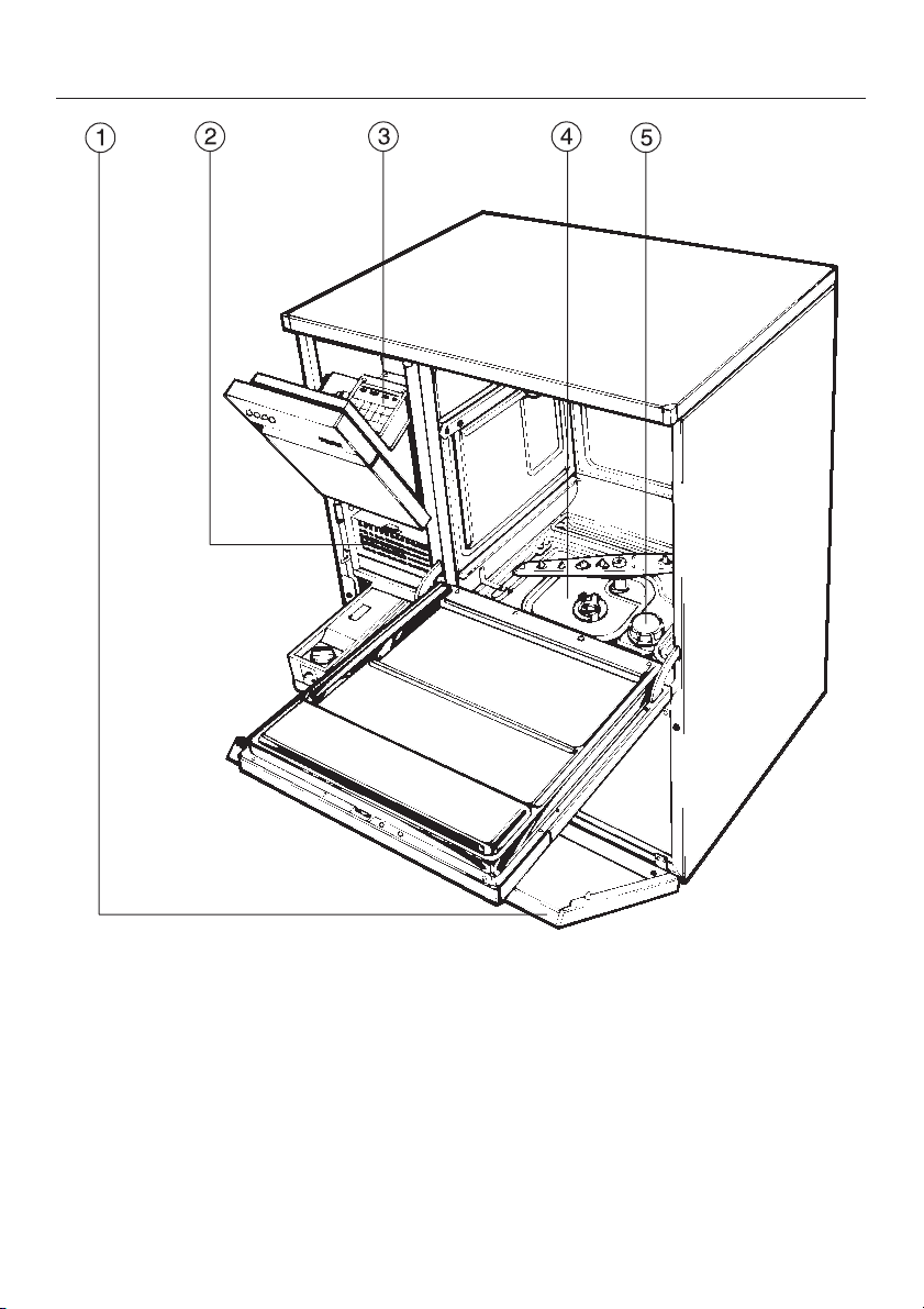
Guide to the machine
a Service Panel
b TA Drying unit
c MCU
d Filter combination
e Reactivation socket for salt
container (water softener)
3
Page 4
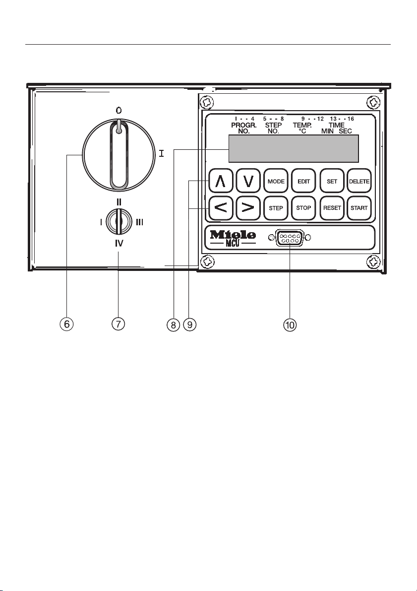
Guide to the machine
MCU
f Main power switch
g Key switch
h Display field
i Operating control pad
j Serial interface
4
Page 5
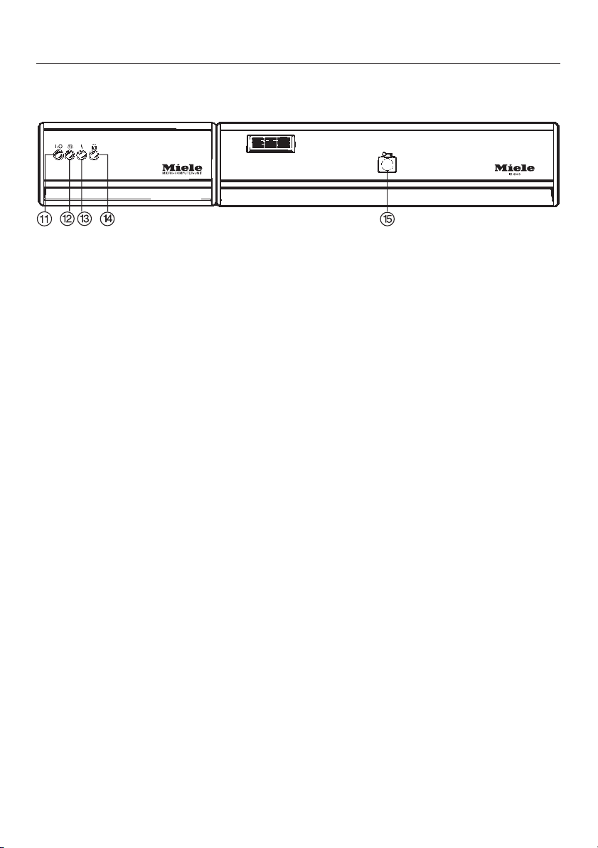
Control indicators
k "On/Off" indicator light
l "In operation" indicator light
m "Fault-Error" indicator light
n "DOS dispenser level" indicator light
o Door release
Guide to the machine
5
Page 6

IMPORTANT SAFETY INSTRUCTIONS
When using an electrical appliance, basic precautions should alwas be followed,
including the following:
READ ALL INSTRUCTIONS BEFORE
USING THE APPLIANCE
Before any maintenance or repair
WARNING -
The manufacturer cannot accept re
sponsibility for damage caused when
the appliance is not used according
to the instructions, or for uses other
than those for which it was intended.
This machine is designed for com-
mercial use and for specialized applications only, as described in these
Operating Instructions. Using it for purposes other than those for which it is
designed could cause damage or injury.
The manufacturer cannot be held responsible for any damage caused by
improper use.
Keep these instructions in a safe place
for future reference.
Please pay attention to the following
notes to maintain safe procedures.
-
work is undertaken, the machine
must be unplugged or disconnected
from the main power supply or the cir
cuit breaker.
A damaged machine is dangerous.
Turn off the power immediately and
call an authorized Miele Service technician.
Unauthorized personnel should not
be allowed access to the machine
or its controls.
Take care when handling liquids
such as detergents, wetting
agents, or neutralizing agents. These
may contain irritant or corrosive ingredients, acids or alkalis. Never use any or
ganic solvent, as the danger of an ex
plosion exists.
Follow all safety instructions. Wear
protective gloves and goggles.
-
-
-
Dot not install the machine in an
area where a danger of explosion
may be present.
The machine should be installed,
repaired and maintained by an au
thorized Miele Service technician. Re
pairs by unqualified persons could be
dangerous.
6
-
-
Page 7

IMPORTANT SAFETY INSTRUCTIONS
The water in the machine must not
be used as drinking water.
Do not sit or lean on the open door,
or rest objects on it. This could
cause the machine to tip and be dam
aged.
Be careful when sorting items with
sharp pointed ends. Position them
in the machine so that you do not hurt
yourself or create a danger for other
operators.
When using this machine at tem
peratures between 158 °F and
203 °F (70 °C and 95 °C) be especially
careful not to scald or burn yourself.
Baskets and inserts must first cool
down. Any water which may remain in
containers will be very hot and should
be emptied into the wash cabinet.
At the end of the drying cycle open
the door to allow the wash load
and inserts to cool down.
Do not touch the heating elements
during or directly after the end of a
program. You could burn yourself.
Never use a hose or steam cleaner
on or near the machine.
When disposing of an old machine,
first make it unusable. Disconnect
the power cord and cut off the plug. For
environmental and safety reasons en
sure the machine is completely drained
of any residual water and cleaning
agent. Make the door lock inoperative,
so that children cannot accidentally
shut themselves in.
-
-
-
The following points should be ob
served to avoid damage to the
IR 6001 and the loads being cleaned.
Use only cleaning agents formu
lated for special processes and
approved by Miele for use with this ma
chine. Use of unsuitable cleaning
agents could adversely affect the load
or the machine. See the enclosed pam
phlet for recommended detergents.
When a chemical additive is rec
ommended, the manufacturer of
the machine takes no responsibility for
the effect of the chemical on the mate
rial of the items being cleaned. Please
be aware of changes in formulation,
storage conditions, concentrations,
etc., which may not be publicized by
the chemical producer, can have a negative effect on the cleaning result.
The machine is designed for oper-
ation with water and cleaning
agents only. Organic solvents must not
be used in the machine, as the danger
of explosion exists under certain cir
cumstances. Although this is not the
case with all organic solvents, other
problems could arise with their use, for
example damage to rubber and syn
thetic materials.
-
-
-
-
-
-
-
-
7
Page 8

IMPORTANT SAFETY INSTRUCTIONS
In critical applications where strin
gent requirements have to be met,
it is strongly recommended that all pro
cess parameters, such as cleaning
agent or quality of water, are discussed
with the Miele Application Technology
specialists.
If the clean objects are subject to
particularly stringent requirements
(e.g. chemical analysis, industrial pro
cesses), a regular quality control test
should be carried out by the user to en
sure that required standards of cleanli
ness are being achieved.
Do not allow any remains of acids,
solvents, or chloride solutions to
get into the wash cabinet. Similarly,
avoid any materials with a corrosive effect. Their presence as compounds in
any solvents should be minimal (especially those in hazard class A1).
To avoid corrosion, ensure that so-
lutions or steam containing acid
salts do not come into contact with the
outer steel casing of the machine.
Do not use any cleaning agent
which adheres to file dust or filings.
Depending on the type and shape of
the file dust, this could damage the cir
culation pump, or cause contact corro
sion.
-
-
-
-
-
Empty any containers before load
ing them into the IR 6001.
Use special inserts in accordance
with the instructions provided.
Waste water must be discharged in
accordance with national and local
water regulations. Consult your local
water authority. Where discharge is in
direct, ensure that the waterborne resi
dues do not exceed statutory limits.
Only equipment made or autho
rized by Miele should be con
nected to this machine. Consult Miele
on the type and application of such
equipment.
SAVE THESE
INSTRUCTIONS
A second set of Safety Instructions
suitable for posting can be found in
the centerfold.
-
-
-
-
-
-
-
8
Page 9

Description of the machine
Applications
The Industrial Cleaner is designed for
specialized sectors of industrial high
technology production, where a consis
tently high standard of cleaning is re
quired, and where the structure of the
items to be cleaned may be complex.
Areas of application are:
Electronics, such as circuit boards
–
and solder frames
Metal cleaning
–
Optics
–
– Particle decontamination
-
Cleaning process
The Industrial Cleaner works on the
principle of fresh water circulation. The
bath time for cleaning and rinsing is
approx. 20-30 minutes. Drying is effected by means of an integrated drying unit. A period of 15 to 45 minutes
must be added to the above time to
thoroughly dry the batch, depending on
the heat retention capacity of the items
in the load and the amount of water re
maining.
-
Water recycling
The IR 6001 comes equipped with a
two stage drainage system, and a
pump to bring rinse water back into the
machine, enabling it to be re-used.
Rinse water which is still quite clean, for
example from the final rinse, can be di
rected into an external holding tank and
be fed back into the machine for the fol
lowing pre-wash or main wash cycle.
The holding tank does not come with
the machine, and must be supplied
on-site. The water from the pre-wash
and main wash is normally discharged
into the waste water system, or into an
effluent treatment plant. The separate
booklet "MCU Program Summary" explains how to program this feature.
-
-
The machine can be programmed, and
a variety of baskets and inserts used,
depending on specific needs.
Special cleaning programs can be writ
ten for individual applications.
-
9
Page 10

Description of the machine
MCU-control
The Industrial Cleaner is controlled by a
micro computer unit. This ensures
maintenance of wash process stan
dards by displaying the current stage of
the process, or an error message if
there is a fault.
The controls can be programmed for a
range of individual applications; for ex
ample, time, temperature, water quality,
dispensing to various liquid detergents
and additives. This enables the user to
adapt the process to individual require
ments. With a large memory capacity,
up to 64 different programs can be
stored and the selected according to
the load to be cleaned. Different keys
are used with the key switch to restrict
access to the operating and programming options.
The control unit has two serial interfaces to allow wash parameters to be
monitored or documented through the
use of a printer or PC (not supplied).
Should your needs change, or the machine be needed for other applications,
different programs can be designed
with the help of Miele.
-
-
-
10
Page 11

First Use
Setting the water hardness
Before using the machine for the first
time the regeneration parameters must
be set by the service technician ac
cording to the local water hardness
level (see MCU operating and program
ming manual).
The local water authority can advise
you of the water hardness in the area.
-
Loading and unloading
Press the door release button and, at
^
the same time, grasp the grip rail and
open the door.
^ Load the items into their respective
baskets and inserts.
See pages on the individual applications for details on loading the machine.
Automatic coupling
The machine is supplied as standard
with an automatic spring-loaded coupling for either the upper basket or a
mobile unit.
Make sure the spring loaded cou
pling engages correctly when a bas
ket, injector or mobile unit is inserted
into the machine, it should be
higher than the water inlet in the roof
of the cabinet. If it is not, adjust the
adapter by:
-
-
3
/8"
Loosening the lock ring.
^
3
Pushing up the adapter (
^
than the water connection inlet) and
re-tightening the lock ring.
-
Removing the upper basket
When the lower basket is being used
alone for large items such as solder
frames, the large spray arm supplied
with the machine should be attached
the water inlet on the roof of the cabi
net.
Remove the upper basket by pulling
^
it forward to the stop position, lifting it
up to the front, and then out of the
wash cabinet.
^ Unscrew the small upper spray arm
retainer and remove the small upper
spray arm.
^ Install the large upper spray arm with
its threaded spindle flange.
Important
Please note that only top baskets,
mobile units or injector nozzle
should be coupled without a spray
arm.
For other applications the small
spray arm should be re-installed.
/8" higher
-
11
Page 12
First Use
Adding detergent
Only use cleaning agents formulated
for special processes and approved
by Miele for use with this machine.
Use of unsuitable cleaning agents
could adversely affect the load or
the machine. Please see the en
closed pamphlet for a list of tested
and recommended cleaning agents
and additives. If you have questions
regarding the suitability of a deter
gent, please contact the Miele Appli
cations Department.
Exercise caution when handling
,
liquid additives. These can contain
irritant or corrosive ingredients.
Take care to ensure that necessary
safety precautions are observed.
Wear protective goggles and gloves
The IR 6001 comes standard with 3
DOS pumps for automatic dispensing
of liquid additives:
-
-
Filling the containers with liquid ad
ditive
The IR 6001 has suction tubes for use
with the external detergent containers.
Select the stopper with the appropriate
thread (depending on the size of the
container). The suction tube length can
be adjusted (see note supplied).
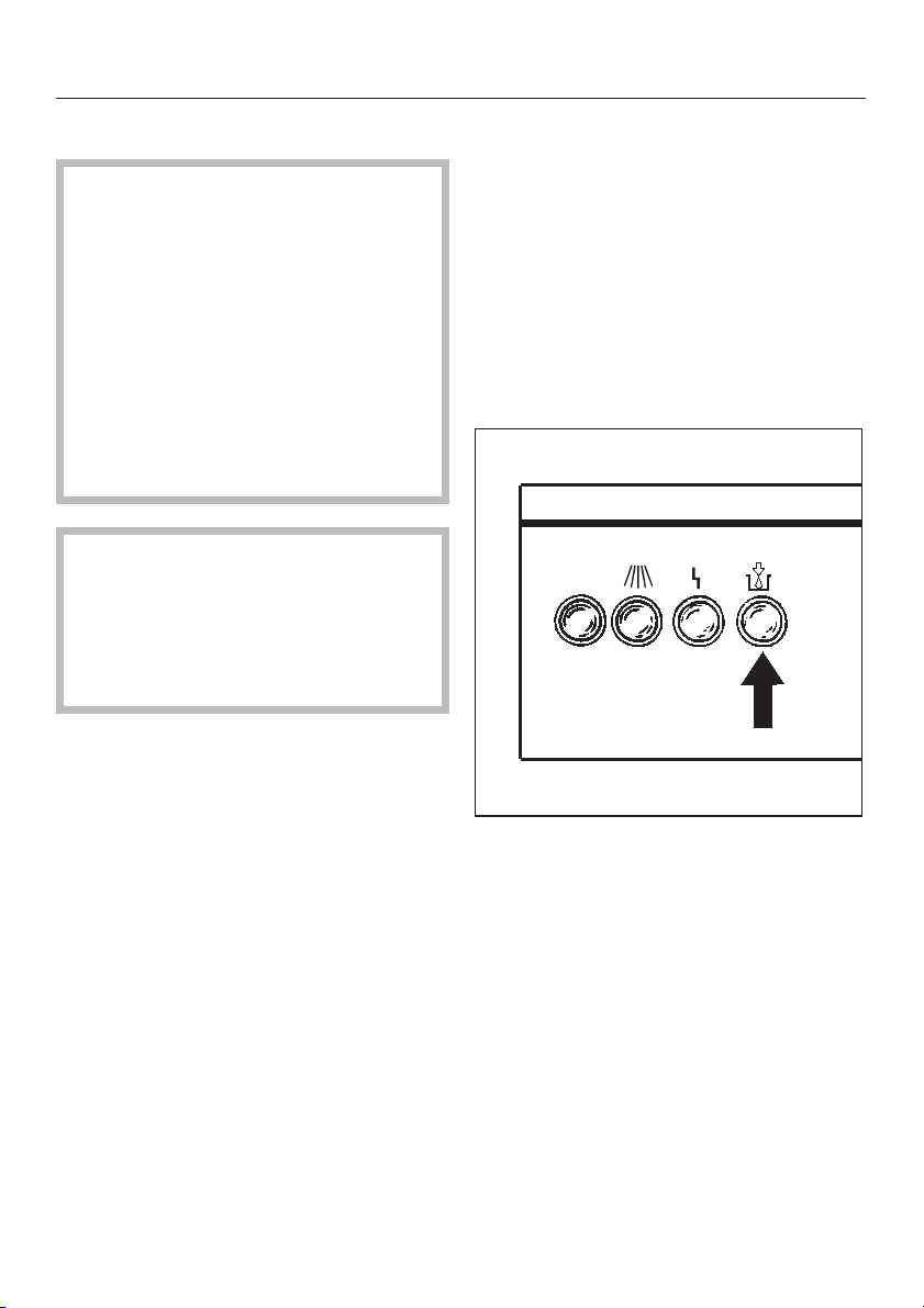
When the containers are full, the DOS
level indicator light v goes out.
-
I-O
-
–
DOS 10/30 injector pump for dis
pensing acid additives. Dispensing
capacity is 10 ml/30 secs (channel
9).
–
2 DOS 60/30 injector pumps for dis
pensing liquid cleaning agent. Dis
pensing capacity is 60 ml/30 secs
(channels 6 and 8).
12
The containers for liquid cleaning
agents must be filled or the DOS level
indicator light v will stay on.
If a dispensing system is not used, the
service technician should remove the
plug connection for this system, to pre
vent the DOS indicator light from stay
ing on.
-
-
Page 13

The containers should not be al
lowed to empty completely and
should be filled regularly, otherwise
the first wash cycle after refilling will
take place without detergent.
The internal dispenser pump hoses
are subject to wear and should be
replaced as preventative mainte
nance every 12 to 18 months.
-
-
First Use
Venting the dispensing
systems
Before using the machine for the first
time, the air has to be expelled from the
dispensing system.
This should also be done if the con
tainer has not been refilled in time and
the despensing system was allowed to
empty completely.
Close the door.
^
Set the key switch to position II.
^
Turn the main switch to I.
^
^ Select program 14 (DOS-FILL/
DOS-FUELL) using the key pads O
or M. "14 DOS-FILL" (or DOS-FUELL)
appears in the display field.
^ Press the START key pad.
^ Repeat the program serveral times if
necessary.
-
Altering the temperature and
drying time
The temperatures for cleaning and dry
ing, as well as the drying times, are
strored for each program (see program
summary supplied).
To change the stored values:
^
Turn the key switch to setting II.
^
Turn the main swich to I.
^
Select the program (see Turning on).
-
13
Page 14

First Use
Altering temperature T1, from 201 °F
to 185 °F (94 °C to 85 °C) (example)
Touch pad
P XXX T1 094
U XXX T1 094
O XXX T1 093
O XXX T1 092
O XXX T1 085
S XXX T1 085
S XXX PROGRAM NAME
Display
XXX PROGRAM NAME
Altering the TA drying temperature
from 194 °F to 176 °F (90 °C to 80 °C)
(example).
Touch pad
P XXX T1 094
P XXX T2 070
P XXX TA 090
U XXX TA 090
N XXX TA 090
O XXX TA 08
S XXX TA 080
S XXX PROGRAM NAME
_ = number flashes
Display
XXX PROGRAM NAME
0
_ = number flashes
XXX = program number selected
Altering the T2 temperature
Start by pressing the touch pad P
twice, then proceed as for temperature
T1.
Note:
Header parameters which have not
been programmed do not appear in the
display.
14
XXX = program number selected
Page 15

Altering the ZA drying time from
30 min to 40 min. (example).
First Use
Touch pad
P XXX T1 094
P XXX T2 070
P XXX TA 090
P XXX ZA 030
U XXX ZA 031
M XXX ZA 031
M XXX ZA 032
M XXX ZA 040
Display
XXX PROGRAM NAME
S XXX ZA 040
S XXX PROGRAM NAME
_ = number flashes
XXX = program number selected
15
Page 16

Operation
Key switch
The following choices can be selected
with the four position key switch, using
the three keys provided:
I = fixed program
(key can be removed)
II = free program selection
III = programing
(see operating and programming
manual).
IV = service mode
(see operating and programming
manual).
A
B
Turning on
1. Free program selection
Key switch setting: II.
^
Turn main switch to I (on).
^
Select program with keys O or M:
^
The program description appears in the
display field.
1 Wafer chip. . . . . . . . . . WAFER-CHIP
2 Semiconductors . . . . . HALBLEITER
3 Solder frames . . . . . . LOETRAHMEN
4 PCB Rosin. . . . . . . . . . . . . . LEI-KOL
5 PCB water . . . . . . . . . . LEI-WASSER
6 Metal . . . . . . . . . . . . . . . . . . METALL
7 PCB oil. . . . . . . . . . . . . . . . . LEI-OEL
10 Fill . . . . . . . . . . . . . . . . . . . FUELLEN
11 Empty . . . . . . . . . . . . . . ENTLEEREN
12 PREFILTER TA *) . . . GROBFILTER *)
The slot in the keyhole (A) points to the
switch position selected (B).
Three keys are supplied, numbered
separately 1, 2 and 3:
Key 1 for switch settings I, II
Key 2 for switch settings I, II, III
Key 3 for switch settings I, II, III, IV
16
13 S-FILTER ta *). . . . . . . FEINFILTER *)
14 DOS-FILL . . . . . . . . . . . DOS-FUELL
15 REGENERATE . . . . . . REGENERIER
*) Only visible when using swich setting
III or IV.
For detailed information on the pro
grams see the supplied program sum
mary.
^
Press the START touch pad.
If the selected program is desired as a
fixed program
^
Turn the key switch to position I.
The key can then be withdrawn.
, it can be stored:
-
-
Page 17

Operation
2. Starting a fixed program
Key switch to position I.
^
Turn main switch to I (On).
^
The pre-selected program appears in
the display field.
Press the START touch pad.
^
The l in operation indicator light co
mes on to show that the machine is run
ning a program.
Note:
If several programs are required as
fixed programs, (i.e. switchable with
key setting I), consult the programming
manual under PROG-SELECTION.
The program parameters (codetext)
can be read off the display without activating any further functions:
00 6 0 0 3 0 0 7 8 1 5 1 0
12 34
1. Program number
-
Program sequence
After starting, the program proceeds
automatically. It is finished when the in
operation light l goes out.
y The Fault-Error indicator light
will come on if the system has been in
terrupted during operation.
-
The cause of the interruption is shown
in the display field as an error mes
sage.
The following error messages are possi
ble:
ERR DOOR
The door has been opened during the
wash program.
ERR INFLOW
Water intake has been impeded (closed
valve, clogged filters, etc.)
ERR DRAIN
Water is not draining freely (kinked
hose, sewer blockage, etc.)
ERR TEMP
Temperature not reached in prescribed
time. Call Miele Technical Service Dept.
-
-
-
2. Current program step
3. Current temperature
4. Remaining step time in minutes and
seconds
Touch the MODE pad to see the current
program segment, (pre-wash, main
wash, interim rinse, final rinse, drying)
or the Codetext.
ERR T-SENSOR
Defective sensor. Call Miele Technical
Service Dept.
ERR PUMP-PRG
Programming fault: several pumps were
activated simultaneously in one pro
gram step.
ERR KEY
Defective key switch. Call Miele Techni
cal Service Dept.
-
17
-
Page 18

Operation
ERR WATER-PRG
Programming fault: more than one
water inlet valve has been activated in
one program step, or an inlet valve has
not been activated in combination with
the circulation pump.
ERR WATERINF
Water inflow time is insufficient. In
crease the ADD-WATER time in the sys
tem parameters.
ERR BATTERY
Change the lithium battery within 4
weeks after this message.
^ If possible, reset the fault and start
the program again.
When the following operating mes-
sages appear in the display, the appropriate action must be taken:
GROBFILTER (PREFILTER)
Change the coarse filter in the drying
unit (see page on drying unit maintenance). Then reset the filter display
message.
^
Key switch position III or IV.
^
Use touch pad O or M to select pro
gram 12 GROBFILTER (Coarse filter).
^
Press the START button.
FEINFILTER (HEPA-Filter)
Call the Miele Technical Service Dept to
change the particle filter in the TA dry
ing unit. (See page on drying unit main
tenance.)
REGENERIER (REGENERATE)
-
-
Interrupting a program
Once a program has been started, it
should only be interrupted in an emer
gency or if the items are moving about
noisily due to incorrect loading.
The machine must be turned off, the
water drained from the wash cabinet
and the program re-started.
Turn the main switch to 0 (off).
^
Wait 5 seconds, the turn the main
^
switch to I (on).
DRAIN is displayed if there is water in
the machine (the water is then pumped
away).
OR the program parameters are displayed with a flashing step time (no
water in the machine).
^ Key switch position II.
^ Press the RESET touch pad.
^ Open the door and arrange the items
properly.
^
Shut the door.
^
Start the program again.
-
Turning off
On completion of the program the ON
indicator light l goes out. If the ma
chine is not to be used again:
^
Turn the main switch to 0 (off). This
disconnects the machine from the
main power supply.
^
Turn off the faucets (water supply).
-
-
Replenish the water softener with salt
(see Reactivating water softener).
18
Page 19

Electronics
Populated circuit boards and solder
frames require cleaning that takes into
account product specifications and the
soldering processes used.
Circuit boards
Circuit boards can be cleaned of resin
residues in the machine. The results
depend on the type of flux used. For in
dividual application, Miele recommends
consultation with cleaning technology
advisors. Cleaning is generally per
formed with tenside additives (0.5 -
0.7% at 149 °F - 167 °F (65 °C - 75 °C)).
The wash/rinse process consists of several stages and purified ion-free water
is used throughout (DI-water).
For surface mount or hybrid technology,
the use of water soluble soft solder
paste is recommended. A high standard of cleaning can then be achieved
by using water and variable temperature washes. This also applies to integrated circuit boards. The time for a
cleaning program is approx. 30 minutes
for the wash phase and 40 - 50 minutes
for the drying phase, depending on the
structural complexity and volume of the
load.
-
Applications Electronics
-
Top basket O 500-10
Baskets designed for circuit boards are
made of plastic coated stainless steel.
These are the O 500-10 top basket and
U 500-10 bottom basket, which to
gether can hold 73 PCBs.
-
Bottom basket U 500-10
19
Page 20

Applications Electronics
Solder frames
Depending on the type of soil, an alka
line cleaning agent at a low concentra
tion of 0.3 - 0.5%, a neutralization agent
or wetting agent (0.1%), is used.
With aluminum solder frames, using
de-ionized water (either throughout or
in the final rinse, depending on quality
standard required) reduces the risk of
damage to the material, which may be
adversely affected by non-purified
water after prolonged use.
Example:
W 16
8 solder frames (L 1811/16" x
29
/32" x D 131/32") (L 475 mm x
W 430 mm x D 45 - 50 mm) can be
cleaned and dried in the machine
within 30 minutes if operated with a hot
water intake of 149 °F (65 °C).
Sample configuration:
Lower basket U 874 with E 500 insert.
-
Insert E 500
20
Page 21

Applications Electronics
Application,
Material/
Soiling
Program P 004
Wash
temperature
T1 (°C)
Wash
temperature
T2 (°C)
Cleaning agent
Concentration
for use
Neutralizer
Concentration
for use
Notes a second
1)
circuit
boards
flux with
resin
LEI-KOL
65 - 75 65 - 75 75
65 65 - 75 65 - 75 65 - 75
1)
neutral,
with tensides
2)
0.5 - 0.7 %
2)
cleaning
agent may be
necessary
circuit
boards
water soluble
flux
P 005
LEI-WASSER
where foam
occurs use
silicone-free
anti-foaming
agent
solder
frames
flux with
resin
P 003
LOETRAHMEN
3 - 10 minutes
alkaline,
with silica
0.5 %
anti-foam
additive
required
slightly acidic,
citric or
phosphoric
acid base
0.1 - 0.15 %
do not use neutralizers if susceptible steel
items are cleaned on the frames
(Delete Step 11), and set T2 to 65 °C.
solder
frames
water soluble
flux
P 003
LOETRAHMEN
65 - 75
alkaline,
with silica
0.5 %
anti-foam
additive not
always required
slightly acidic,
citric or
phosphoric
acid base
0.1 - 0.15 %
1) Characteristics of cleaning and neutralizing agents are given, not product names.
2) Concentration for use = percentage of the chemical additive in the wash water solution
Water requirement / wash cycle = approximately 15 liters, e.g.:
0.1 % = 0.5 fl.oz. (15 ml) or 15 g amount to be dispensed
0.3 % = 1.6 fl.oz. (45 ml) or 45 g amount to be dispensed
0.5 % = 2.6 fl.oz. (75 ml) or 75 g amount to be dispensed
0.7 % = 3.7 fl.oz. (105 ml) or 105 g amount to be dispensed
21
Page 22

Applications Metal Cleaning
Cleaning metal
The machine can be used for cleaning
products requiring degreasing, removal
of dust or polishing/grinding paste, or
pre-treatment before painting or galva
nizing.
Cleaning agents and wash parameters
can be selected according to the prop
erties of the iron, steel or non-ferrous
metal. A test wash is advisable with pol
ishing/grinding pastes to identify the
most suitable cleaning processes.
-
-
-
A final rinse with de-ionized water is of
ten necessary, especially with non-ferrous metals, to achieve the cleaning result required.
Make sure that no file dust or
,
other fillings, (from drilling, milling
etc), especially from iron based materials, are introduced into the machine.
The upper basket O-188 and lower
basket U 874 are recommended as a
basic basket set for the machine.
-
22
Page 23

IMPORTANT SAFETY INSTRUCTIONS
To the person responsible for the machine:
Make this pull-out with the Warning and Safety Instructions available to any op
^
erators of the machine. Place it near the machine, where it can be seen.
Ensure that operators know and understand these Warning and Safety Instruc
^
tions, and observe them in use.
When using an electrical appliance, basic precautions should always be followed,
including the following:
READ ALL INSTRUCTIONS BEFORE
USING THE APPLIANCE
Please pay attention to the following
WARNING -
The manufacturer cannot accept responsibility for damage caused when
the appliance is not used according
to the instructions, or for uses other
than those for which it was intended.
This machine is designed for com-
mercial use and for specialized applications only, as described in these
Operating Instructions. Using it for pur
poses other than those for which it is
designed could cause damage or in
jury.
The manufacturer cannot be held re
sponsible for any damage caused by
improper use.
Keep these instructions in a safe place
for future reference.
notes to maintain safe procedures.
Dot not install the machine in an
area where a danger of explosion
may be present.
The machine should be installed,
repaired and maintained by an authorized Miele Service technician. Repairs by unqualified persons could be
dangerous.
-
-
-
Before any maintenance or repair
work is undertaken, the machine
must be unplugged or disconnected
from the main power supply or the cir
cuit breaker.
A damaged machine is dangerous.
Turn off the power immediately and
call an authorized Miele Service techni
cian.
-
-
-
-
1
Page 24

IMPORTANT SAFETY INSTRUCTIONS
Unauthorized personnel should not
be allowed access to the machine
or its controls.
Take care when handling liquids
such as detergents, wetting
agents, or neutralizing agents. These
may contain irritant or corrosive ingredi
ents, acids or alkalis. Never use any or
ganic solvent, as the danger of an ex
plosion exists.
Follow all safety instructions. Wear
protective gloves and goggles.
The water in the machine must not
be used as drinking water.
Do not sit or lean on the open door,
or rest objects on it. This could
cause the machine to tip and be damaged.
Be careful when sorting items with
sharp pointed ends. Position them
in the machine so that you do not hurt
yourself or create a danger for other
operators.
-
When using this machine at tem
peratures between 158 °F and
203 °F (70 °C and 95 °C) be especially
careful not to scald or burn yourself.
Baskets and inserts must first cool
down. Any water which may remain in
containers will be very hot and should
be emptied into the wash cabinet.
At the end of the drying cycle open
the door to allow the wash load
and inserts to cool down.
Do not touch the heating elements
during or directly after the end of a
program. You could burn yourself.
Never use a hose or steam cleaner
on or near the machine.
When disposing of an old machine,
first make it unusable. Disconnect
the power cord and cut off the plug. For
environmental and safety reasons ensure the machine is completely drained
of any residual water and cleaning
agent. Make the door lock inoperative,
so that children cannot accidentally
shut themselves in.
-
2
Page 25

IMPORTANT SAFETY INSTRUCTIONS
The following points should be ob
served to avoid damage to the
IR 6001 and the loads being cleaned.
Use only cleaning agents formu
lated for special processes and
approved by Miele for use with this ma
chine. Use of unsuitable cleaning
agents could adversely affect the load
or the machine. See the enclosed pam
phlet for recommended detergents.
When a chemical additive is rec
ommended, the manufacturer of
the machine takes no responsibility for
the effect of the chemical on the mate
rial of the items being cleaned. Please
be aware of changes in formulation,
storage conditions, concentrations,
etc., which may not be publicized by
the chemical producer, can have a negative effect on the cleaning result.
The machine is designed for oper-
ation with water and cleaning
agents only. Organic solvents must not
be used in the machine, as the danger
of explosion exists under certain cir
cumstances. Although this is not the
case with all organic solvents, other
problems could arise with their use, for
example damage to rubber and syn
thetic materials.
-
-
-
-
-
-
In critical applications where strin
gent requirements have to be met,
it is strongly recommended that all pro
cess parameters, such as cleaning
agent or quality of water, are discussed
with the Miele Application Technology
specialists.
If the clean objects are subject to
-
particularly stringent requirements
(e.g. chemical analysis, industrial pro
cesses), a regular quality control test
should be carried out by the user to en
sure that required standards of cleanli
ness are being achieved.
Do not allow any remains of acids,
solvents, or chloride solutions to
get into the wash cabinet. Similarly,
avoid any materials with a corrosive effect. Their presence as compounds in
any solvents should be minimal (especially those in hazard class A1).
To avoid corrosion, ensure that so-
lutions or steam containing acid
salts do not come into contact with the
outer steel casing of the machine.
Do not use any cleaning agent
which adheres to file dust or filings.
Depending on the type and shape of
the file dust, this could damage the cir
culation pump, or cause contact corro
sion.
-
-
-
-
-
-
-
3
Page 26

IMPORTANT SAFETY INSTRUCTIONS
Empty any containers before load
ing them into the IR 6001.
Use special inserts in accordance
with the instructions provided.
Waste water must be discharged in
accordance with national and local
water regulations. Consult your local
water authority. Where discharge is in
direct, ensure that the waterborne resi
dues do not exceed statutory limits.
Only equipment made or autho
rized by Miele should be con
nected to this machine. Consult Miele
on the type and application of such
equipment.
-
-
SAVE THESE
INSTRUCTIONS
-
-
-
4
Page 27

Applications Metal Cleaning
Application
Material/
Soiling
Program P 006 METALL or
Wash
temperature
T1 (°C)
Wash
temperature
T2 (°C)
Cleaning
1)
agent
Concentration
for use
Neutralizer
Concentration
for use
Notes If a neutralizer is needed, select P 006, delete Step 5 (P 006),
stainless
steel
oil, grease,
particles etc.
P 007 LEI-OEL
65 - 75
(2 - 10 min)
65 - 75 50 - 65 50 - 60 40 - 50
mildly alkaline, to
highly alkaline
2)
0.3 - 0.5 %
also possible:
alkaline with silica
and neutral
(see Aluminum)
0.3 - 0.5 %
1)
not always
necessary to
neutralize
with a phosphoric
acid product
when using
alkaline cleaner
2)
0.1 - 0.15 %
and add a Step (Channel 9 and 14) between Steps 11 and
12 (P 006).
If no neutralizer and only a small amount (0.3 %) of cleaning
agents is dispensed, select P 007.
If the cleaning agent is low-foam delete Step 4 (P 007).
Aluminum
oil, grease,
particles etc.
P 006 METALL or
P 007 LEI-OEL
55 - 70
(2 - 5 min)
neutral or alkaline
with silica
(3-5 ml) use
only alkaline
product with
silica
sometimes
necessary for
a citric acid
based neutralizer
when using
alkaline cleaner
with silica
0.1 - 0.15 %
bright metal,
eg. brass,
oil, grease,
particles etc.
P 006 METALL or
P 007 LEI-OEL
55 - 65
(2 - 5 min)
neutral to alkaline
0.3 - 0.5 %
not highly
alkaline
addition of
citric or phosphoric acid based
neutralizer often
brightens the
surface
0.1 - 0.15 %
non-stainless
steel
oil, grease,
particles etc.
P 007 LEI-OEL
60 - 75
(2 - 10 min)
alkaline to
highly alkaline
(pH > 10)
0.3 - 0.5 %
not mildly
alkaline or
neutral
no acid
neutralization
Dispense an an
ti-corrosion additive
during water intake
for interim rinse and
final rinse. Delete
Step 4 in P 007
-
1) Characteristics of cleaning and deneutralizing agents are given, not product names
2) Concentration for use = percentage of the chemical additive in the wash water solution
Water requirement / wash cycle = approximately 15 liters, e.g.:
0.1 % = 0.5 fl.oz. (15 ml) or 15 g amount to be dispensed
0.3 % = 1.6 fl.oz. (45 ml) or 45 g amount to be dispensed
0.5 % = 2.6 fl.oz. (75 ml) or 75 g amount to be dispensed
0.7 % = 3.7 fl.oz. (105 ml) or 105 g amount to be dispensed
23
Page 28

Applications Optics
Optics
In the production of optical items the
machine can be used for degreasing,
removing dust or polishing/grinding
paste, and giving a final rinse to clear
the items of residues. The quality of the
final rinse depends on the quality of the
water. With polishing pastes it is advis
able to investigate the suitability of the
cleaning process for the type of glass
ware being cleaned.
-
-
Insert E 118-10
24
Page 29

Applications Optics
Application
Material/Soiling
Program P 006 METALL or
Wash temperature
T1 (°C)
Wash temperature
T2 (°C)
Cleaning agent
Concentration
for use
Neutralizer
Concentration
for use
Notes If a neutralizer is needed, select P 006, delete Step 5 (P 006), add a Step
1) Characteristics of cleaning and neutralizing agents are given, not product names
2) Concentration for use = percentage of the chemical additive in the wash water solution.
Water requirement / wash cycle = approximately 15 liters, e.g.:
1)
2)
1)
2)
Optical Glass
Dust/particles etc.
P 007 LEI-OEL
60 - 75
50 - 60
mildly alkaline, alkaline
0.3 - 0.5 %
Neutralization with product containing phosphoric component sometimes
necessary
0.1 - 0.15 %
(Channel 9 and 14) between Steps 11 and 12 (P 006).
If no neutralizer and only a small amount (0.3 %) of cleaning agent is
dispensed, select P 007.
If the cleaning agent is low-foam delete Step 4 (P 007).
0.1 % = 0.5 fl.oz. (15 ml) or 15 g amount to be dispensed
0.3 % = 1.6 fl.oz. (45 ml) or 45 g amount to be dispensed
0.5 % = 2.6 fl.oz. (75 ml) or 75 g amount to be dispensed
0.7 % = 3.7 fl.oz. (105 ml) or 105 g amount to be dispensed
25
Page 30

Applications Particle Decontamination
Particle decontamination
The IR 6001 offers exceptional cleaning
results and is recommended for particle
decontamination of chip boxes, wafer
trays, drainers, fitting racks, computer
components etc. Decontamination is
accomplished with the addition of a
minimal amount of a special cleaning
agent in a purely aqueous system, with
out the addition of solvents. In these
applications the cleaning process is
carried out using de-ionized water
throughout the wash-program.
Miele offers a wide variety of inserts for
different applications, not all of which
can be shown here. Please contact
Miele for details of other inserts available.
-
26
Page 31

Reactivating the water softener
Before using the machine for the first
time, the MCU must be set by the servi
ce technician to reactivate the water
softener according to the local water
hardness level (see Operating and pro
gram manual). The local water authority
can advise you of the water hardness in
the area.
When, after a number of wash cycles,
the message REGENERIER (REGEN
ERATE) appears in the display, the
built-in water softener is depleted and
cannot supply any more soft water. It
must therefore be reactivated with re
generate salt immediately after the
program has ended.
If this cannot be done immediately and
further batches have been washed, the
reactivation process must be carried
out twice in succession.
For each reactivation program you will
need:
-
-
The salt container must only be
,
filled with salt!
Filling the salt container with any
thing but salt, such as detergent,
could cause pressure to build in the
salt container resulting in harm
(chemical burns, physical injury) to
the operator.
To fill the salt container
-
– 4.4 lbs. (2 kg) reactivation salt (gran-
ule size must be 1-4 mm).
–
The plastic salt container supplied as
standard equipment with the ma
chine.
Please note
Never use rock salt as the dirt parti
cles it contains will block the water
softener unit.
Reactivation salt with granules
smaller than 1 mm or larger than
4 mm must not be used.
-
-
^
Unscrew and remove the filter insert
from the salt container.
^
Fill the salt container with granular
salt and replace the filter insert.
27
Page 32

Reactivating the water softener
To insert salt container
Remove the bottom basket from the
^
wash cabinet.
^ Unscrew the plastic cap in the base
of the wash cabinet.
Close the door.
^
Turn on the faucets (water supply).
^
Select program 15 REGENERIER
^
(Regenerate/Reactivate). See "Turn
ing on".
The reactivation program proceeds au
tomatically and is finished when the l
indicator light goes out.
Then:
Turn off the machine.
^
Open the door and remove the salt
^
container.
^ Replace the plastic cap on the
socket at the bottom of the wash cabinet.
^ Replace the lower basket.
^ Rinse the salt container and filter in-
sert under running water.
^ Turn off faucets (water supply).
-
-
^
Place the salt container on the reacti
vation socket and screw firmly into
place.
28
The water pressure must be al least
36 psi.
If the flow pressure is below 36 psi,
salt residues may be left in the salt
container. If this is the case, the
REGENERIER program must be run
again.
-
Page 33

Serial interfaces
The serial interfaces are RS 232 com
patible.
The interface enables data transfer be
tween the MCU and an EPSON com
patible printer or IBM compatible PC.
The MCU offers the following timed
printout options:
Date and machine number,
–
Program start (with program number,
–
step number),
Program end,
–
Confirmation that programmed tem
–
perature has been reached, and any
applicable Code-texts,
– Temperature,
– All faults (with parameters, where
given),
– All manual interventions.
At older MCU Versions (until version
S2.05 inkl.) the use of the interfaces is
not permitted.
,
Use ONLY the interface cable
provided by MIELE, as some of the
contact points on the MCU interface
are non-standard RS 232. An unap
proved cable could damage the
MCU and peripheral equipment.
-
The following connection cables are
-
available from Miele:
-
-
-
45 ft. (15 m) connection cable for
–
short-term connection between the
MCU front interface and a PC or
printer.
45 ft. (15 m) connection cable for
–
long-term connection between the
MCU rear (internal) interface and a
PC or printer.
6 ft. (2 m) connection cable for
–
short-term connection between the
MCU front interface and a PC.
When connecting a printer or PC to the
MCU please note the following points:
– When installing the machine take the
dimensions of the printer or PC into
account.
– After removing the interface cable,
replace the black cap on the interface socket.
The function PRINT must be selected in
the system parameters SERIAL-MODE/
FUNCTION, for the report printer to be
activated. At the same time the Baud
rate (transfer speed) of the printer must
be set on the MCU.
The following baud rates are possible:
1200, 2400, 4800, 9600, 19200.
29
Page 34

Serial interfaces
Preparing the MCU for report
printout
1. Set the baud rate (transfer speed)
of the printer
Turn the key switch to position III or IV.
Touch pad
W PROGRAMMING
M SYSTEMPARAMETER
W CTEXT SPECIALS
MM SERIAL MODE
W BAUDRATE nnn
U BAUDRATE nnn
Display
ZZZ PROGRAM NAME
2. Select communication type
"PRINT" (printer connection)
Touch pad
a)
M FUNCTION PROG
U FUNCTION PROG
M FUNCTION PRINT
S FUNCTION PRINT
T ZZZ PROGRAM NAME
b)
or alternatively if "PRINT" has already
been set:
M FUNCTION PRINT
T ZZZ PROGRAM NAME
Display
BAUDRATE XXX
O
..
..
..
O BAUDRATE XXX
S BAUDRATE XXX
30
___ = number sequence flashes
XXX = baud rate to be set
ZZZ = program number selected
nnn = stored baud rate
Page 35

Consult the supplier on the availability
of dedicated PC programs. (Programs
listed below may be universally obtain
able).
MCU-Protokoll-Manager (Report
printout manager
This program can be used to record
and store report data, load from a data
carrier, and print from an Epson com
patible or HP-LaserJet printer.
MCU-programming software
In addition to programming through the
MCU keyboard, was programs can be
created on a PC, stored, and transferred to the MCU.
-
Serial interfaces
-
31
Page 36

Cleaning and Care
Cleaning the filters in the wash
cabinet
The wash water passes through a four
filter combination in the base of the
wash cabinet which consists of:
Coarse filter
–
Fine filter
–
Flat filter
–
Micro-fine filter
–
It is important that the filters are kept
clean (otherwise the water overflow sys
tem cannot function reliably).
The filter combination has been designed so that most of the soil is collected in the coarse filter.
The coarse filter should be inspected
and, if necessary, cleaned after every
program.
,
Glass fragments, needles,
pieces of wire etc. may have collected in this filter, and could cause
injuries.
Cleaning the coarse filter
-
^ Press the two tabs inwards and re-
move the filter.
^ Clean the filter.
^ Replace the filter and press until it
clicks into place.
Fine filter
The filer filter is located under the
coarse filter. It will trap very small items
that are not caught in the coarse filter.
Whenever the coarse filter is cleaned,
the fine filter should be removed and in
spected.
-
32
^
To remove, lift out the fine filter and
clean.
^
Replace the filter by inserting it into
the center of the micro-fine filter.
Page 37

Cleaning the flat and microfine filters
Remove the coarse and fine filters.
^
^ To unscrew the micro-fine filter, take
hold of the two tabs, turn twice in a
counter-clockwise direction and remove together with the flat filter.
Cleaning and Care
^ Clean all the filters.
^ Replace the filter combination se-
curely in the reverse order in which it
was removed.
,
The machine must not be used
without all the filters in place!
33
Page 38

Cleaning and Care
Cleaning the water inlet filters
Two filters incorporated into the water
inlet system protect the valves from
particles that may be in the water sup
ply. The filters must be cleaned when
dirty, or insufficient water flows into the
wash cabinet.
Turn off the water valves.
^
Disconnect the inlet hoses.
^
Remove the filter housing from the
^
water valve.
Remove the filer insert (1) from the
^
housing and clean or replace, if necessary. Clean the filter located in the
hose connector (2).
-
2
^ Reinstall the filters. Connect the
hoses and turn on the valves to test
for leaks.
A third filter is located in the solenoid
valve and should only be cleaned or
replaced by an authorized technician.
1
34
Page 39

Changing the coarse filter
The coarse filter should be changed
when dirty or after approximately 100
operating hours ("GROBFILTER" ap
pears in the MCU control display).
^ Pull the top of the inlet grill out, then
lift up, off of the retainers, and remove.
-
Drying unit: Cleaning and Care
^ Change the coarse filter.
The smooth side of the filter should
face the rear.
^ Position the perforated plate at the
base and press into place at the top.
The edges should face forward.
^ On replacing the inlet grill, it should
click into place.
^
Take out the perforated plate.
Exchanging the HEPA particle
filter
This filter should be replaced every 500
hours, or when "FEINFILTER" is dis
played.
,
This filter should only be
changed by an authorized Service
technician.
Reproducible operation of the machine
can only be achieved if original Miele
HEPA particle filters are used.
-
35
Page 40

Correcting minor faults
Repairs should only be under
,
taken by an authorized technician.
Heater limiter
The IR 6001 is equipped with a thermal
breaker which shuts off the heating ele
ments if the machine overheats. The
breaker reset can be found on the
right-hand side behind the service
panel.
Symptoms:
The water in the wash cabinet does not
heat up; the program cycle takes too
long, or the fault message F TEMP is
displayed.
Overheating can occur if large items
cover the heater elements preventing
them from transfering heat to the water.
It can also occur if the filters in the
wash chamber are blocked, or too little
water has been taken into the wash
chamber.
-
Remedy:
Isolate and correct the cause of the
^
problem.
Clean the filters in the water inlet.
^
Reset the heater by:
-
Removing the service panel and
^
Pressing the blue reset button on the
^
heater limiter.
The Miele Technical Service
,
Dept. should be called if the thermal
breaker trips again.
USA: 1-800-999-1360
CDN: 1-800-565-6435
36
Page 41

Installation
This machine must be con
,
nected to the water supply in accor
-
dance with all national and local
plumbing codes!
Faucets and drain connections should
be situated as close to the machine as
possible, and be easily accessible. The
cold and hot water supply flow pressure
should be between 36 and 145 psi (2.5
and 10.0 bar). The machine is supplied
with 4 connection hoses 5 ft. (1.5 m)
long with
3
/4" (19 mm) female hose
thread ends. Do not shorten the hoses!
Where flow pressure is between 5 and
36 psi (0.3 and 2.5 bar), fill time may be
extended by reprogramming the machine. The machine cannot be operated with an inflow pressure of less
than 5 psi (0.3 bar).
Requirements (refer to IR 6001 MCU
Installation Diagram for corresponding
numbers):
1. Cold water connection:
1
One
/2" (13 mm) cold water supply line
with a standard
3
/4" (19 mm) male hose
thread faucet is needed. The cold water
supply hose is marked with blue tape.
2. Hot water connection:
1
One
/2" (13 mm) hot water supply line
with a standard
3
/4" (19 mm) male hose
thread faucet is needed. The water
temperature must not exceed 150 °F
(65 °C) (recommended: 140 °F / 60 °C).
The hot water supply hose is marked
with red tape.
This hose may also be connected to a
cold water supply, if hot water is not
available.
3. DI water connection:
1
One
/2" (13 mm) de-ionized water sup
ply line with a standard
3
/4" (19 mm)
male hose thread faucet is needed.
Flow pressure should be between 25
and 145 psi (1.5 and 10.0 bar). Where
flow pressure is between 5 and 25 psi
(0.3 and 1.5 bar), fill time may be ex
tended by reprogramming the machine.
The machine cannot be operated con
ventionally with an inflow pressure of
less than 5 psi (0.3 bar). In this case
the installation of an optional DI pump
is required. The DI water supply hose is
marked with green tape.
This hose may also be connected to a
cold water supply, if DI water is not
available, and where the local water
hardness does not exceed 100 ppm
CaCO
.
3
4. Tank water connection:
The machine has a 1" (25 mm) connection socket. A connection hose from the
holding tank to the machine is not sup
plied as standard. This connection
hose must be installed from the bottom
of the tank to the machine, with a down
ward gradient, and should not be
looped or inclined (see item 4 on en
closed diagram). Minimum height for
the supply connection is 14" (35 cm).
-
-
37
Page 42

Installation
5. Drain connection to the sewage
system:
The machine comes equipped with a
flexible drain hose
7
/8" (22 mm) internal
diameter, 5 ft. (1.5 m) long, with appro
priate hose clamps. It can be con
nected to a drain pipe or a 1
1
/4" (32
-
mm) minimum diameter stand pipe. The
drain pipe must be able to accept a
flow volume of 13.2 gal/min. (50 l/min.).
Do not decrease the diameter of the
drain connection at any point to less
3
than
/4" (19 mm).
This hose must not be shortened. An in
crease in length up to 13 ft. (4 m) is
possible using a
7
/8" (22 mm) internal
diameter hose (available through Miele
Technical Service). Maximum drain
height is 3 ft. (1 m).
6. Drain connection to the holding
tank:
The machine comes equipped with a
flexible drain hose
7
/8" (22 mm) internal
diameter, 5 ft. (1.5 m) long, for connec
tion to a holding tank.
7. Electrical connection:
All electrical connections must
,
be made by a qualified electrician
and meet all national and local
codes.
The machine comes equipped for con
nection to a three phase power supply:
Three phase 208 V AC
–
6.6 kW connected load
–
20 A circuit breaker per phase
–
A dedicated three phase line incorpo
rating the appropriate circuit breakers
(specified above) should be situated
near the appliance. The machine comes supplied with a 6-foot 4 X 12 AWG
cord (without a plug), that may be hardwired into an appropriate electrical box,
or plugged in via the use of a 3 pole, 4
wire grounding plug and receptacle
(NEMA type L15-20R and L15-20P are
recommended).
-
-
-
This hose must not be shortened. An in
crease in length up to 13 ft. (4 m) is
possible using
7
/8" (22 mm) internal di
ameter hose (available through Miele
Technical Service). Do not decrease he
internal diameter of the drain connec
tion at any point to less than
3
/4"
-
(19 mm).
Maximum drain height is 3 ft. (1 m).
38
-
-
Page 43

Installation
8. Vent connection:
The machine is equipped with a venting
socket at the rear. It must be connected
to a vent pipe to be provided on-site.
The vent must be able to accept a mini
mum volume of 3,530 cfm
(100 m³/min.). Using an adapter it is
possible to obtain venting up to 15 ft.
(5 m) in length with HT pipe (HT - able
to withstand high temperatures), 2
3
/4"
(70 mm) internal diameter. Deduct a
nominal 20" (50 cm) from the maximum
length for each bend. Where several
machines are installed, each one must
be connected individually as described
above to the main ducting. The main
duct must have a minimum diameter of
4" (100 mm), and work with
underpressure.
9. Connection to cleaning agent containers:
The connection hoses for the three integrated DOS dispenser pumps can be
directed through the rear to either side
of the machine. Maximum distance of
the agent containers is 43" (107.5 cm)
to the left, or 15" (37.5 cm) to the right.
10. Holding tank (not supplied with
the machine):
An external holding tank is not supplied
with the machine, but must be provided
-
on-site if required. The tank should be
positioned to the left of the machine
(viewed from the front). If the user
wishes to connect a holding tank to the
machine, the following conditions have
to be met:
The water level in the tank must not
–
rinse above 37
1
/4" (950 mm), mea
sured from the base level of the ma
chine in position. The tank must be
provided with an unrestricted overflow at this height. There must still be
a capacity of 5
1
/2gal. (20 l) in the
tank above this level.
– The drain outlet from the holding tank
must be situated at least 13
(350 mm) high, measured from the
base level of the machine in position.
The connection hose must be laid so
that there is an uninterrupted downward gradient from the holding tank
to the connection on the machine.
–
The holding tank must be vented.
-
-
3
/4"
–
There is no inlet filter in line with the
suds recycling pump. It is the re
sponsibility of the user to take suit
able steps (e. g. using a lid) to en
sure that no impurities enter the
holding tank. If this is not possible, a
filter should be installed in the hold
ing tank at the outlet connection.
The holding tank and its connection
hose must be provided on site.
-
-
-
-
39
Page 44

Help to protect our environment
Disposal of the packing mate
rial
The transport and protective packing
materials are environmentally friendly
for disposal and can normally be recy
cled. Please recycle.
Disposal of an old appliance
-
Old appliances contain materials that
may be recyclable. Please contact your
local recycling authority about potential
recycling, before disposing of the appli
ance. See also the section under
"Warning and Safety instructions".
When disposing an old machine,
,
first make it unusable. Disconnect or
cut off the plug and cable. For envi
ronmental and safety reasons en
sure the machine is completely
drained of any residual water and
cleaning agent. (Observe safety regulations and wear safety goggles
and gloves). Make the door lock inoperative, so that children cannot
accidentally shut themselves in. The
simplest way to do this is to remove
the locking pin (2 philips screws
above the door). Make appropriate
arrangements for the safe disposal
of the machine).
-
-
-
404142
Page 45

Page 46

Page 47

43
Page 48

Alteration rights reserved / 000 2101
 Loading...