


Installation instructions
Commercial dishwasher
G 8051
To avoid the risk of accidents or
damage to the machine it is
essential to read the operating and
installation instructions before it is installed,
commissioned or used for the first time.
G
M.-Nr. 06 667 030

Contents
Installing integrated "i" Dishwashers . . . . . . . . . . . . . . . . . . . . . . . . . . . . . . . . . 3
1. Fitting protective cover plate to worktop . . . . . . . . . . . . . . . . . . . . . . . . . . . . . . . 5
2. Building the dishwasher into a niche. . . . . . . . . . . . . . . . . . . . . . . . . . . . . . . . . . 6
Slides . . . . . . . . . . . . . . . . . . . . . . . . . . . . . . . . . . . . . . . . . . . . . . . . . . . . . . . . . 6
Securing pieces . . . . . . . . . . . . . . . . . . . . . . . . . . . . . . . . . . . . . . . . . . . . . . . . . 7
Angle connector . . . . . . . . . . . . . . . . . . . . . . . . . . . . . . . . . . . . . . . . . . . . . . . . . 7
3. Matching the fascia panel to the height of adjacent drawer fronts . . . . . . . . . . 9
4. Fitting the (matching) door front . . . . . . . . . . . . . . . . . . . . . . . . . . . . . . . . . . . . 10
Fitting the fixing bracket . . . . . . . . . . . . . . . . . . . . . . . . . . . . . . . . . . . . . . . . . . 10
Fitting and securing the door front . . . . . . . . . . . . . . . . . . . . . . . . . . . . . . . . . . 12
5. Securing the dishwasher. . . . . . . . . . . . . . . . . . . . . . . . . . . . . . . . . . . . . . . . . . . 14
6. Adjusting the door springs . . . . . . . . . . . . . . . . . . . . . . . . . . . . . . . . . . . . . . . . 15
7. Matching the plinth facing of a kitchen run . . . . . . . . . . . . . . . . . . . . . . . . . . . . 16
2

Installing integrated "i" Dishwashers
Integrated ("i") dishwashers
"i" dishwashers are specially designed
for building under a continuous
worktop.
The accessories are included with "i"
–
dishwashers in a separate package
for on-site fixing.
The front of the dishwasher is
–
designed to take a front panel. It can
be fitted with a furniture door front to
match the rest of the kitchen.
The dishwasher does not have a
–
plinth facing. The plinth area of the
dishwasher needs to be covered
either with a plinth facing to match
the kitchen furniture or with one
which can be ordered as a special
accessory. The separate plinth
facing can be height adjusted to suit
the kitchen. The plinth return is freely
adjustable.
To ensure stability, "i" and "U"
,
model dishwashers must only be
installed under a continuous worktop
which must be securely screwed to
neighbouring units.
The dishwasher must not be
,
installed under a hob. The high
radiant temperatures which are
sometimes generated by a hob
could damage the dishwasher.
Instructions for installing the
dishwasher are described in the
following sections.
3
Installing integrated "i" Dishwashers
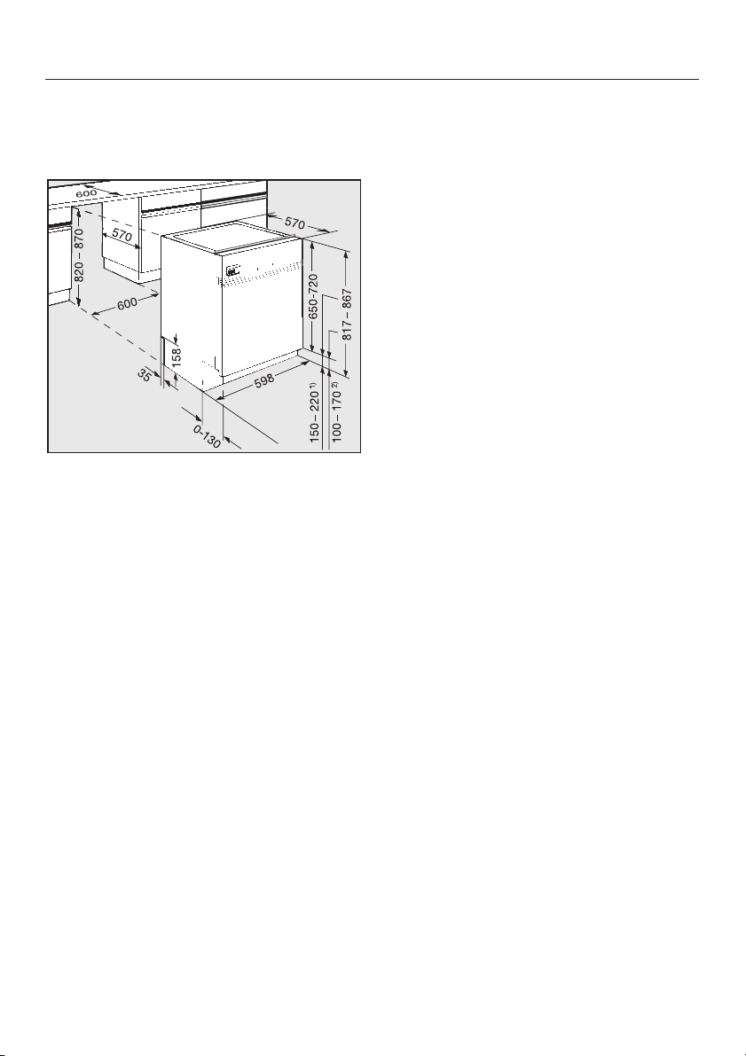
Building in dimensions
Dishwasher model G 8051
1) Niche height 870 mm
2) Niche height 820 mm
Adjustment range approx. 5 cm
(82 - 87 cm total height).
Extended machine feet are available at
extra cost, (special accessory) where a
machine height of 87 to 92 cm is
required.
4
Installing integrated "i" Dishwashers
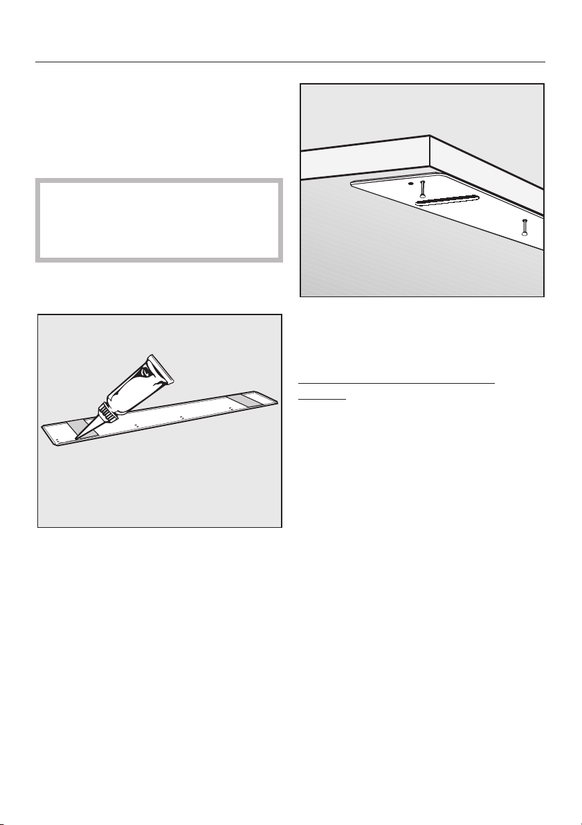
1.Fitting protective cover plate
to worktop
The underside of the worktop is
protected against steam rising from the
machine by a special cover plate.
If two different materials meet up
,
at the front edge of the worktop, then
the join must be concealed by the
cover plate.
Remove the protective backing from
^
the cover plate.
Use the tacks supplied to nail the
^
cover plate to the underside of the
worktop.
Worktops with wood or laminate
edging:
^ Nail the tacks through the holes
further back from the edge.
^
Squeeze sealant from the tube
supplied all the way along the hollow
moulding in the cover plate.
^
Align the cover plate to the front
edge of the worktop in the middle of
the niche.
^ Use soapy water to wipe off any
excess sealant.
5
Installing integrated "i" Dishwashers
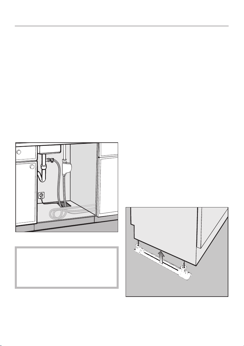
2.Building the dishwasher
into a niche
Connection to water and drainage
should be sited beside and not behind
the dishwasher for accessibility.
Connections are usually made in the
area under the sink. Many kitchen unit
manufacturers provide a cut-out in the
base of the sink base unit for the hoses
to be fed through.
If the base unit has no opening and if
there is not an opening through the
plinth area for connections, one must
be cut.
Dishwasher height
Adjust the height manually before
^
installing the dishwasher.
Leave a space of approx. 5 mm
below the worktop to allow the
dishwasher to be pushed back easily
into the recess. Make sure that the
dishwasher stands level.
It is easier to adjust the screw feet if the
weight of the dishwasher is not bearing
down on them.
If possible tip the machine slightly.
Slides
You will find the slides in the upper
basket of the dishwasher.
They make installation of the
dishwasher easier and protect the floor
from possible damage when moving
the appliance into and out of the
recess. They are also used for
adjusting the height of the rear screw
feet.
Dimensions: 60 x 110 mm.
,
There must be no electrical
sockets behind the dishwasher.
Danger of overheating and fire risk if
the dishwasher were to be pushed
up against a plug.
6
^
Fit the slides - with the ratchet at the
rear - under the screw feet.

Installing integrated "i" Dishwashers
Securing pieces
To ensure stability, the dishwasher must
be fixed securely to the worktop (step 5).
Two securing pieces are supplied for
this purpose.
^ Fit the securing pieces into the slots
on both the left and right hand sides.
Granite and marble worktops
With these worktops the dishwasher
must be securely screwed to
neighbouring units on the right and left
hand sides. For this you will require two
special fixing brackets which are
available at extra cost (special
accessory).
:
Angle connector
The angle connector for the water
drainage hose at the rear of the
dishwasher can be turned.
Turn the angle connector in the
^
direction of the on-site connection for
the drainage hose.
^ Push the dishwasher right back into
the recess. Ensure that the drain
hose, inlet hose and the electric
cable are laid to reach the
connection point without any kinks.
7

Installing integrated "i" Dishwashers
Front screw feet
Now adjust the feet until the seal on
the top of the dishwasher is right up
against the underside of the
worktop, to which it will be screwed
later. Ensure that the dishwasher
stands level.
Rear screw feet
^ Use a TORX T20 screwdriver to
adjust the rear screw feet
required height.
Higher = turn clockwise
Lower = turn anti-clockwise
Several turns are needed to adjust
1 mm in height.
to the
^ Adjust the front screw feet
or with a flat blade screwdriver.
manually
8

Installing integrated "i" Dishwashers
3.Matching the fascia panel to
the height of adjacent drawer
fronts
The fascia panel can be aligned with
the drawer fronts by adjusting the
spacer bars.
^ Using an 8 mm socket spanner turn
clockwise or anti-clockwise until the
required height is reached.
Adjustment range:
from 112 mm: Fascia panel
without spacer bars
to 145 mm: Fascia panel with
up to 4 spacer bars
to 154 mm: when using an extra
(fifth) spacer bar
(special accessory at
extra cost)
After adjustment cut off any
protruding lengths of screws.
If necessary some or all spacer bars
can be removed.
^
Press out the spacer bars from the
fitting slits in the fascia panel.
9

Installing integrated "i" Dishwashers
4.Fitting the (matching) door
front
Fixing brackets are already fitted on
stainless steel door fronts. These fronts
cannot be shortened.
(Go to "Fitting and securing the door
front".)
The door of a kitchen base unit (without
drawer front or fittings) is normally used
for the door front.
If a kitchen door front is not available, a
panel with the following dimensions
may be used:
Width:
590 - 597 mm
Thickness:
the same thickness as the neighbouring
door fronts but a minimum of 16 mm.
Height:
Dimension X
Fitting the fixing bracket
A fixing bracket must be fitted to the
rear of the door front panel. This is then
used for attaching the door front panel
to the door outer panel on the machine.
Templates are provided to position the
fixing bracket and the door front
accurately.
^ On each side of the fixing bracket
position a template with the rule
markings facing outwards.
10

Installing integrated "i" Dishwashers
Hang the fixing bracket into the slits
^
in the machine door outer panel.
^ Push the overhanging ends of the
templates under the fascia panel.
Take off the fixing bracket.
^
Lay the door front down with the rear
^
side facing upwards.
^ Lay the bracket on the rear side of
the door front and adjust so that:
– the marks on the template for the
upper edge of the adjacent base unit
doors match the top edge of the
door front.
^
Adjust the fixing bracket a:
The long holes in the machine outer
door must be aligned with the
matching markings on the template.
^
Mark the height of the top edge of
adjacent kitchen base unit doors on
the template b.
– the fixing bracket must be the same
distance from the left and right hand
side edges of the door front.
^
Use strips of adhesive tape to hold
the bracket in this position.
11

Installing integrated "i" Dishwashers
Fitting and securing the door front
Drill the fixing holes to a depth of
^
about 10 mm, using a 2.5 mm drill
bit.
^ Secure the fixing bracket to the door
front using the countersunk screws
supplied.
^ Take off the templates.
^ Hang the door front into the slits in
the machine door outer panel.
Keep the templates in case the
dishwasher is ever fitted with a new
door front.
12
^
Open the dishwasher door slightly.

Installing integrated "i" Dishwashers
Adjust the door front height on one
^
side and lightly screw in a T20 Torx
screw on this side.
Adjust the door front height on the
^
other side and also lightly screw in a
T20 Torx screw on this side.
Close the dishwasher door.
^
Check the alignment of the door
^
panel.
If it is not correctly aligned you may
^
need to loosen the screws and readjust it to the correct alignment.
Once the door front is correctly
positioned:
Open the dishwasher door.
^
Tighten all the Torx screws on the
^
sides.
Plug the openings for the fixing
^
screws using the plastic stoppers
provided.
Door fronts differ in weight and it
,
is therefore essential that the door
springs are adjusted after the door
front has been fitted. See Step 6.
13

Installing integrated "i" Dishwashers
5.Securing the dishwasher
Open the dishwasher door.
^
The holes in the securing pieces
must line up with the long holes in
the worktop cover plate. If this is not
the case, adjust the position of the
dishwasher in the niche (ensure that
the dishwasher is the same distance
from the neighbouring kitchen units
on the right and left hand sides and
line the dishwasher door front up
with neighbouring door fronts).
Screw the countersunk screws
^
(3.9 x 22) supplied upwards through
the securing pieces on the left and
right hand sides into the work surface
to secure the dishwasher.
Ensure that the seal on the top edge
of the dishwasher fits directly
against the worktop. If this is not the
case, adjust the height adjustable
feet some more (see Step 2).
14

Installing integrated "i" Dishwashers
6.Adjusting the door springs
The door springs are correctly adjusted
if the door remains stationary when left
open at 45 °.
If the door drops down, then the door
springs need to be tightened.
If it closes then the springs need to be
loosened.
The adjusting screw is located in the
upper front strip at the left hand side of
the dishwasher.
Please note:
If the door front is too heavy for the
door springs (i.e. the door falls open)
then stronger springs should be fitted.
Please contact your Miele dealer or the
Miele Spare Parts Department for
advice.
Half open the dishwasher door.
^
The door springs are easier to adjust
when the door is only half open than
when it is fully open.
^ Adjust the door spring with a Torx
T20 or a 1 x 5.5 mm screwdriver until
it is correctly balanced:
- Turn clockwise = tighten
- Turn anti-clockwise = loosen.
15

Installing integrated "i" Dishwashers
7.Matching the plinth facing
of a kitchen run
The plinth area of the dishwasher is
normally covered with a plinth run
matching the kitchen furniture.
The height (H) of the plinth facing in
front of the dishwasher depends on the
plinth return (R) and how much the
door front extends below the
dishwasher door (P).
Place the plinth facing directly in front
^
of the kitchen run but do not attach.
Carefully open the dishwasher door.
^
If the door front comes into contact with
the kitchen plinth when the dishwasher
door is opened the plinth facing in the
area behind the dishwasher door needs
to be cut to size.
To do this mark where the edge of the
^
door front comes into contact with the
plinth facing.
Cut the plinth facing to size along this
^
line.
^ Place the plinth facing in front of the
kitchen run again and check whether
the dishwasher door can be opened
fully.
If it cannot, trim the plinth facing
again until the correct size is
achieved.
^ Secure the plinth facing to the
adjacent kitchen units in accordance
with the kitchen furniture
manufacturer’s instructions.
161718
If your kitchen does not have a plinth
run matching the kitchen furniture, the
plinth area can be covered with a
separate plinth kit, available at extra
cost (special accessory).


19

Alteration rights reserved G 8051 / 2705
M.-Nr. 06 667 030 / 00
 Loading...