

Page 1
Operating instructions
for the Ventilation System
DA 326 i
DA 329 i
To prevent accidents
and machine damage,ö]
read these Operating Instructions
before installation or use.
UV
M.-Nr.
05 473 640
Page 2

Contents
Help protect our environment. . . . . . . . . . . . . . . . . . . . . . . . . . . . . . . . . . . . . . . . 3
Warning and Safety instructions . . . . . . . . . . . . . . . . . . . . . . . . . . . . . . . . . . . . . 4
Guide to the appliance . . . . . . . . . . . . . . . . . . . . . . . . . . . . . . . . . . . . . . . . . . . . . 7
Description of the functions . . . . . . . . . . . . . . . . . . . . . . . . . . . . . . . . . . . . . . . . . 9
Operation . . . . . . . . . . . . . . . . . . . . . . . . . . . . . . . . . . . . . . . . . . . . . . . . . . . . . . . 10
Cleaning and care
Housing . . . . . . . . . . . . . . . . . . . . . . . . . . . . . . . . . . . . . . . . . . . . . . . . . . . . . . . . . 11
Grease filters . . . . . . . . . . . . . . . . . . . . . . . . . . . . . . . . . . . . . . . . . . . . . . . . . . . . . 11
External filter . . . . . . . . . . . . . . . . . . . . . . . . . . . . . . . . . . . . . . . . . . . . . . . . . . . 12
Internal filter . . . . . . . . . . . . . . . . . . . . . . . . . . . . . . . . . . . . . . . . . . . . . . . . . . . 12
Inserting / replacing the active charcoal filter . . . . . . . . . . . . . . . . . . . . . . . . . . . . 14
Defective lighting . . . . . . . . . . . . . . . . . . . . . . . . . . . . . . . . . . . . . . . . . . . . . . . . . 15
After Sales Service . . . . . . . . . . . . . . . . . . . . . . . . . . . . . . . . . . . . . . . . . . . . . . . 16
Appliance dimensions . . . . . . . . . . . . . . . . . . . . . . . . . . . . . . . . . . . . . . . . . . . . 17
Installation
Installation accessories . . . . . . . . . . . . . . . . . . . . . . . . . . . . . . . . . . . . . . . . . . . . . 21
1. Non-return flap. . . . . . . . . . . . . . . . . . . . . . . . . . . . . . . . . . . . . . . . . . . . . . . . . . 23
2. Reducing collar . . . . . . . . . . . . . . . . . . . . . . . . . . . . . . . . . . . . . . . . . . . . . . . . . 24
3. Runners . . . . . . . . . . . . . . . . . . . . . . . . . . . . . . . . . . . . . . . . . . . . . . . . . . . . . . . 24
4. Hang the cabinet door. . . . . . . . . . . . . . . . . . . . . . . . . . . . . . . . . . . . . . . . . . . . 25
5. Position the appliance in the cabinet. . . . . . . . . . . . . . . . . . . . . . . . . . . . . . . . . 26
6. Align the height of the appliance. . . . . . . . . . . . . . . . . . . . . . . . . . . . . . . . . . . . 26
7 a. Installation of a DFB lightshield . . . . . . . . . . . . . . . . . . . . . . . . . . . . . . . . . . . 27
7 b. Installation of a custom lightshield to match cabinetry . . . . . . . . . . . . . . . . . 27
8. Align the depth of the appliance . . . . . . . . . . . . . . . . . . . . . . . . . . . . . . . . . . . . 28
9 a. Install side spacers at the sides of the appliance . . . . . . . . . . . . . . . . . . . . . 28
9 b. Spacer strip for the rear of the appliance. . . . . . . . . . . . . . . . . . . . . . . . . . . . 29
9 c. Light cover . . . . . . . . . . . . . . . . . . . . . . . . . . . . . . . . . . . . . . . . . . . . . . . . . . . 29
10 a. Vented extraction . . . . . . . . . . . . . . . . . . . . . . . . . . . . . . . . . . . . . . . . . . . . . 30
10 b. Set up for recirculation mode connection. . . . . . . . . . . . . . . . . . . . . . . . . . . 31
11. Electrical connection . . . . . . . . . . . . . . . . . . . . . . . . . . . . . . . . . . . . . . . . . . . . 31
Special installation instructions
Installation into a cabinet with 19 mm thick walls. . . . . . . . . . . . . . . . . . . . . . . 32
Installing in a 35
Air extraction . . . . . . . . . . . . . . . . . . . . . . . . . . . . . . . . . . . . . . . . . . . . . . . . . . . . 34
Electrical connection. . . . . . . . . . . . . . . . . . . . . . . . . . . . . . . . . . . . . . . . . . . . . . 36
Technical data . . . . . . . . . . . . . . . . . . . . . . . . . . . . . . . . . . . . . . . . . . . . . . . . . . . 37
7
/16 " (90 cm) wide cabinet: . . . . . . . . . . . . . . . . . . . . . . . . . 32
2
Page 3
Help protect our environment
Disposal of packing materials
The cardboard box and packing materi
als protect the appliance during ship
ping. They have been designed to be
biodegradable and recyclable. Please
recycle.
-
Disposal of your old appliance
Old appliances contain materials that
can be recycled. Please contact your
local recycling center about the possi
bility of recycling these materials.
Before discarding an old appliance,
unplug it from the outlet and cut off
its power cord and remove any
doors to prevent it from becoming a
hazard.
-
3
Page 4
Warning and Safety Instructions
Read these Operating Instructions carefully before installing or using the
Ventilation System.
Do not connect the appliance to
This appliance is intended for resi
dential use only. Use the appliance
only for its intended purpose. The
manufacturer cannot be held re
sponsible for damages caused by
improper use of the hood.
-
-
the main electrical supply using an
extension cord. Extension cords do not
meet the safety requirements of this ap
pliance.
Do not turn on the hood until it has
been properly installed.
-
Read all the instructions before in
stalling or using for the first time.
SAVE THESE INSTRUCTIONS AND
REVIEW THEM PERIODICALLY
CAUTION
For General Ventilating Use Only. Do
Not Use To Exhaust Hazardous Or
Explosive Materials And Vapors.
This appliance is designed to vent
cooking smoke \ odors only.
Be certain your appliance is prop
erly installed and grounded by a
qualified technician.
To guarantee the electrical safety
of this appliance, continuity must
exist between the appliance and an ef
fective grounding system. It is impera
tive that this basic safety requirement
be met. If there is any doubt, have the
electrical system of the house checked
by a qualified electrician. The manufac
turer cannot be held responsible for
damages caused by the lack, or inade
quacy of, an effective grounding sys
tem.
-
-
Repairs on electric appliances
should only be performed by quali
fied technician. Do not repair or replace
any part of the appliance unless specifically recommended in this manual.
Before servicing, disconnect the
power supply by either removing
the fuse or unplugging the unit or manually "tripping" the circuit breaker.
When installing the hood, make
sure that the minimum safety distances between cooktops and the hood
are maintained.
– For electric cooktops: 18" (45 cm)
– For gas cooktops: 26" (65 cm)
– For a Miele open grill: 26" (65 cm)
Do not install this exhaust hood
over cooktops burning solid fuel.
-
-
-
-
-
4
Page 5

Warning and Safety Instructions
WARNING
To reduce the risk of fire, use only
metal ductwork.
Any fittings, sealant, or materials used
to install the ductwork must be made of
approved non-flammable materials.
Never connect an exhaust hood to
an active chimney, dryer vent, vent
flue, or room ventilating ductwork. Seek
professional advice before connecting
an exhaust hood vent to an existing, in
active chimney or vent flue.
Never operate gas burners without
pots. Heat generated by prolonged
operation of gas burners without pots
could damage the hood.
Do not flambé beneath the exhaust
hood. Flames could be drawn up
into the hood by the suction or the
grease filters may ignite.
Do not allow children to play with
the hood or its controls.
WARNING
TO REDUCE THE RISK OF A RANGE
TOP GREASE FIRE:
Keep the fan, filters and grease
laden surfaces clean.
Always turn hood "ON" when cook
ing at high heat.
Use high range settings on range
only when necessary. Heat oil
slowly on low to medium setting.
Don't leave range unattended
when cooking.
Always use cookware and utensils
appropriate for the type and
amount of food being prepared.
-
Do not leave cooking surfaces un
attended while in use. Overheated
food can ignite.
Do not use the exhaust hood with
out the grease filters in place.
Clean the grease filters regularly.
Dirty filters are a fire hazard.
Do not use a steam cleaner to
clean the hood. The steam could
penetrate to electrical components and
cause a short circuit.
-
-
5
Page 6

Warning and Safety Instructions
WARNING
TO REDUCE THE RISK OF INJURY
TO PERSONS IN THE EVENT OF A
RANGE TOP GREASE FIRE,
OBSERVE THE FOLLLOWING:
Smother flames with a close fitting
lid, cookie sheet, or metal tray, then
turn off the burner.
Be careful to prevent burns.
If the flames do not go out immediately,
evacuate and call the fire depart
ment.
Never pick up a flaming pan - You
may be burned.
Do not use water, including wet
dishcloths or towels - a violent
steam explosion will occur.
Use an extinguisher
only if:
– You know you have a Class ABC ex-
tinguisher, and you already know
how to operate it.
–
The fire is small and contained in the
area where it started.
–
The fire department is being called.
–
You can fight the fire with your back
to an exit.
-
WARNING
TO REDUCE THE RISK OF FIRE,
ELECTRIC SHOCK, OR INJURY TO
PERSONS,
OBSERVE THE FOLLOWING:
Use this unit only in the manner in
tended by the manufacturer. If you
have questions, contact the manufacturer.
Before servicing or cleaning the
unit, turn power off at circuit
breaker and lock the service discon
necting means to prevent power from
being turned on accidentally. When the
service disconnecting means cannot
be locked, securely fasten a prominent
warning device, such as a tag, to the
service panel.
Installation and electrical work
must be performed by qualified
technicians in accordance with all applicable codes and standards.
Make sure that the airflow in the
room is sufficient for combustion
and exhausting of all non-electric heat
ing appliances (water heaters, gas
cooktops, gas ovens, etc.), otherwise
back drafts may occur. Follow the heat
ing maunfacturer's guidelines and
safety standards or those published by
the National Fire Protection Association
(NFPA), or the American Society for
Heating, Refrigeration and Air Condi
tioning Engineers (ASHRAE).
If in doubt, consult an experienced pro
fessional.
-
-
-
-
-
-
Be careful not to damage hidden
electrical wiring or plumbing when
cutting or drilling into the wall or ceiling.
Ducted fans must always be
vented outdoors.
6
Page 7
Warning and Safety Instructions
When connecting the hood to an ex
ternal vent, make sure that there is
adequate ventilation in the room
where the exhaust hood is to be
used.
When using the hood in the same area
as other appliances requiring room air
(e.g. non-electric water heaters, gas
cooktops, gas ovens, etc.) make cer
tain that the air extracted by the hood
does not hinder their operation. These
appliances need air for combustion.
Adequate ventilation can be maintained
by installing air vents in windows or
walls or by ensuring that the hood can
only be turned on when the other appliances are off, or vice versa.
To prevent combustion gases being
drawn back into the room by the exhaust hood, the underpressure in the
room must be no greater than 0.0006
psi (0.04 mbar) when the hood and
these appliances are running simulta
neously.
-
-
-
Disposal of old appliances
Before discarding an old appliance, re
move its power cord and any doors to
prevent it from becoming a hazard.
SAVE THESE INSTRUCTIONS AND
REVIEW THEM PERIODICALLY
Throughout the manual, important
safety items will be highlighted in
boxes and should be read in con
junction with these "Warning and
Safety instructions".
-
-
If there are any doubts as to whether
there is adequate ventilation, consult an
experienced professional.
7
Page 8
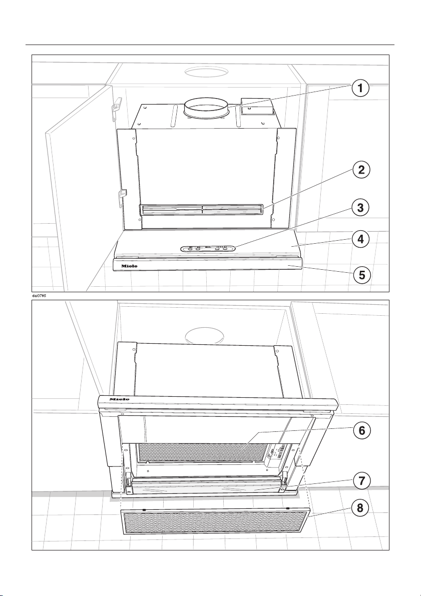
Guide to the appliance
8
Page 9
Guide to the appliance
a Vent connection
b Active charcoal filter slot
c Control panel
d Pull-out
deflector plate
e DFB Facia Panel
(must be ordered separately)
f Internal grease filter
g Overhead cooktop light
h External grease filter
i Light button
j On/Off button
k Power level buttons
Four fan speed selection
9
Page 10

Description of the functions
The hood works
...by air extraction:
The air is drawn in, cleaned by an ex
ternal filter and then passed through an
internal filter before being directed out
side.
The hood has a non-return flap , (see
"Installation").
This flap is closed when the hood is off.
No exchange of room air and outside
air can take place. When the hood is
turned on the non-return flap opens for
the cooking odors to be blown outside.
...by air recirculaton:
The air is drawn in and cleaned first by
the external filter, then by the internal filter before passing through an active
charcoal filter. The cleaned air is then
recirculated back into the kitchen
through a vent in the top of the hood.
Before using the hood for the first
time in recirculation mode, make
sure that the active charcoal filter is
in place. See Section on "Cleaning
and care".
-
-
10
Page 11
Operation
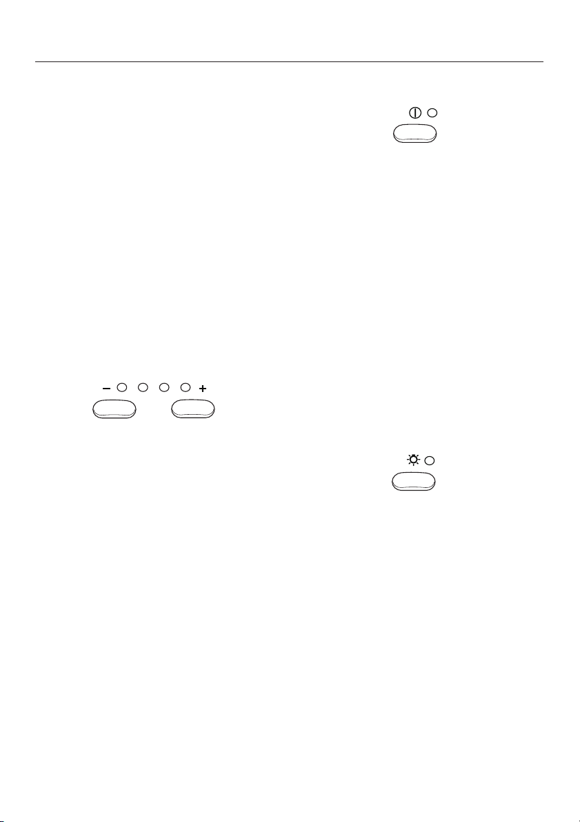
Turning the fan on
Pull the deflector plate out approxi
^
mately 2" (5 cm).
The hood will then begin to operate at
power level "II".
Selecting the power level
Depending on how much the air needs
to be filtered, there are four power lev
els available.
For normal cooking a low to medium
level is usually sufficient.
For frying or cooking food with a strong
aroma the highest level is recommended.
Lower level Higher level
^ Use the power level buttons to select
the power level required.
-
Turning the fan off
Press the On/Off button to turn the
^
fan off
or
Push the deflector plate back in.
^
The next time the deflector plate is
pulled out the hood will operate at
power level "II".
Turning the light on
The light for illuminating the cooktop
can be turned on or off independently
of the fan.
^ Pull the deflector plate out approxi-
mately 1.5" (3 cm).
The indicators show which power level
has been chosen.
11
^
Press the light button.
^
When the light is turned on the indi
cator next to the button illuminates
To turn the light off:
^
Press the light button again.
or
^
Push the deflector plate back in.
The next time the deflector plate is
pulled out the light will come back on.
-
Page 12
Cleaning and care
Before servicing or cleaning the
hood, disconnect it from the power
supply by "tripping" the circuit
breaker, removing the fuse or un
plugging it.
Make sure power is not restored to
the appliance while maintenance or
repair work is performed.
Housing
Lacquered surfaces can be cleaned
using a solution of hot water and liquid
soap. Dry with a soft cloth.
For stainless steel surfaces use a mild
non-abrasive stainless steel cleaner.
Never use cleaners which scour or
contain chlorine, acids or soda.
These will damage the surface of the
hood.
-
Grease filters
The hood has 2 re-usable metal filters
which remove solid particles (oil, dust,
etc.) from the vented kitchen air.
The hood has an external filter which is
visible on the underside of the appli
ance. An internal filter is situated above
it in the appliance.
The filters should be cleaned every
3 – 4 weeks to avoid a build-up of fat.
Clean the filters immediately if they are
obviously dirty.
Important! Always clean both filters.
A dirty filter is a fire hazard.
-
12
Page 13

Cleaning and care
External filter
To remove the external filter pull the
^
deflector plate out slightly.
Turn the fan off.
^
^ Holding the external filter at the front
tilt it approximately 1" (3 cm) downwards and then pull it towards you to
remove it.
Internal filter
^ Pull the deflector plate out to its full
extension.
The internal filter will now be visible.
Clean the filters –
^
– by hand: with a nylon brush in a
mild solution of warm water and liq
uid soap.
– in a dishwasher: place the filters
with the short side upright in the
lower basket, checking that the spray
arm is not blocked.
DA 329: The external grease filter can
be folded and cleaned in the dishwasher by twisting the latches as
shown.
Cleaning filters in the dishwasher
may cause permanent discoloration.
However, the performance of the fil
ters will not be affected.
-
-
^
Holding it by the handle pull it down
wards to remove it.
^
After cleaning, place the filters on a
towel to dry before putting them back
in place.
^
When removing the filters for clean
ing also clean off any residues of oil
or fat from the now accessible hous
ing to prevent fires.
-
-
-
13
Page 14

Cleaning and care
Replace the filters
Internal filter:
Fit the filter into the appliance so that
^
it hooks into position at the back,
then push it up at the front and make
sure it engages in position on the left
and right hand sides.
External filter:
Make sure that the red plastic
^
guides are at the front and facing up.
^ Insert the external filter into the
extended deflector plate and hold it
in position.
^
DA 329:
–
Twist the grease filter catch as
shown.
–
Unfold the grease filter and lock the
catch.
14
^
Tilt the rear of the filter up and gently
push it in until it snaps into place.
Page 15

Inserting / replacing the active
charcoal filter
Cleaning and care
For recirculation mode an active char
coal filter must be used in addition to
the grease filters. It is designed to absorb cooking odors.
The active charcoal filter is inserted into
the slot on the front of the appliance.
Replacement active charcoal filters
can be ordered from the Miele Technical Service Department at
1-800-999-1360.
Please quote
part number 05 182 190
Follow the instructions supplied with the
active charcoal filter when inserting it.
Always replace the filter immediately, if
it is no longer absorbing cooking odors.
However, it should be replaced at least
every 6 months.
-
15
Page 16

Cleaning and care
Defective lighting
If the light does not work the bulb may
need replacing or the starter could be
defective.
Before servicing or cleaning the
hood, disconnect it from the power
supply by "tripping" the circuit
breaker, removing the fuse, or un
plugging it.
Make sure power is not restored to
the appliance while maintenance or
repair work is performed.
-
Take out the external filter as already
^
described.
^ Unscrew the fixing screws on the
right and left hand sides of the light
cover. While undoing the screws hold
the cover securely so that it does not
drop on to the cooktop below!
^ Lower the cover to remove it.
^ Replace the fluorescent bulb or the
starter.
^ Replace the cover and secure in po-
sition with the fixing screws.
16
^
Replace the external filter.
Page 17

In the event of a problem which you
can not fix yourself, please contact:
Your Miele dealer
–
or
The Miele Technical Service Depart
–
ment,
(see address on back cover).
When contacting the Technical Service
Department, please quote the model
and serial number of your appliance,
both of which are shown on the data
plate, visible when the grease filters are
removed.
-
After Sales Service
17
Page 18

Appliance dimensions
18
Page 19

Appliance dimensions
* The DFB light shield must be pur
chased separately.
** For these dimensions to be applica
ble the rear panel of the upper cabi
net may have to be removed.
To ensure that the exhaust ducting can
be installed on the exhaust connection
easily, the upper cabinet must be at
least 460 mm high.
The slot for the active charcoal filter
–
a must be accessible if the appli
ance is being used in recirculation
mode.
The DA 327i can also be built into a 60
cm cabinet. In this case, the lower portion of the hood will overlap the bottom
cabinets on either side.
-
-
-
-
19
Page 20

Appliance dimensions
Installation in cabinetry
The depth of the installation depends
on what type of light shield is used and
the dimensions of surrounding
cabinetry.
Hood installed with a DFB light
shield
To install the hood so that the light
shield is flush with the adjacent
cabinetry, the following dimensions
must be used. (Please refer to the met
ric conversion table)
A = minimum of 273 mm when using a
16 mm thick door panel
A = minimum of 270 mm when using a
19 mm thick door panel
Hood installed with a cabinet match
ing light shield (custom made)
If wall cabinets have a decorative mold
ing along their lower edge, a matching
light shield can be made and mounted
on the hood. To do this the minimum
distance necessary (B) behind the light
shield will be 275 mm.
-
-
20
Page 21

Appliance dimensions
The adjustable filler strip C can be
used to conceal gaps of 10 to 70 mm
between the rear of the appliance and
the wall or cabinet back.
If the cabinet does not have a back
panel and there are no units to the
side of it then a traverse must be
used to provide the unit with extra
stability.
A traverse is available from the Miele
Spare Parts Department in the ap
propriate width (Miele DT 60 and DT
90).
-
Metric conversion table
Millimeters. . . . . . . . . . . . . . . . . . Inches
10 . . . . . . . . . . . . . . . . . . . . . . . . . . .3/8
15 . . . . . . . . . . . . . . . . . . . . . . . . . . .5/8
19 . . . . . . . . . . . . . . . . . . . . . . . . . . .3/4
30. . . . . . . . . . . . . . . . . . . . . . . . . 13/16
40. . . . . . . . . . . . . . . . . . . . . . . . . 19/16
70 . . . . . . . . . . . . . . . . . . . . . . . . . 23/4
75. . . . . . . . . . . . . . . . . . . . . . . . . . . . 3
85. . . . . . . . . . . . . . . . . . . . . . . . . . 33/8
88 . . . . . . . . . . . . . . . . . . . . . . . . . 31/2
100. . . . . . . . . . . . . . . . . . . . . . . . . . . 4
115. . . . . . . . . . . . . . . . . . . . . . . . 49/16
125. . . . . . . . . . . . . . . . . . . . . . . 415/16
150. . . . . . . . . . . . . . . . . . . . . . . 515/16
165. . . . . . . . . . . . . . . . . . . . . . . . . 61/2
170. . . . . . . . . . . . . . . . . . . . . . . 611/16
175. . . . . . . . . . . . . . . . . . . . . . . . . 67/8
255. . . . . . . . . . . . . . . . . . . . . . . 101/16
258. . . . . . . . . . . . . . . . . . . . . . . 103/16
270. . . . . . . . . . . . . . . . . . . . . . . . 105/8
273. . . . . . . . . . . . . . . . . . . . . . . . 103/4
275. . . . . . . . . . . . . . . . . . . . . . 1013/16
285 . . . . . . . . . . . . . . . . . . . . . . . 111/4
345. . . . . . . . . . . . . . . . . . . . . . . 139/16
359. . . . . . . . . . . . . . . . . . . . . . . . 141/8
460. . . . . . . . . . . . . . . . . . . . . . . . 181/8
470 . . . . . . . . . . . . . . . . . . . . . . . 181/2
562. . . . . . . . . . . . . . . . . . . . . . . . 221/8
568. . . . . . . . . . . . . . . . . . . . . . . . 223/8
595. . . . . . . . . . . . . . . . . . . . . . . 237/16
600. . . . . . . . . . . . . . . . . . . . . . . . 235/8
862. . . . . . . . . . . . . . . . . . . . . . 3315/16
868. . . . . . . . . . . . . . . . . . . . . . . 343/16
895. . . . . . . . . . . . . . . . . . . . . . . . 351/4
900. . . . . . . . . . . . . . . . . . . . . . . 357/16
21
Page 22

Installation
Installation accessories
22
Page 23

Installation
a 1 hose clip for securing the vent
ducting to the vent connection.
b 1 reducing collar
for exhaust ducting of 5" (125 mm)
diameter.
c 1 non-return flap
for fitting into the vent connection.
d 2 runners
(1 x right, 1x left) to support the ap
pliance in the cabinet.
e 2 spacer blocks (DA 329 only)
for installing the appliance in a
7
35
/16" (90 cm) wide cabinet.
f 2 cover caps (DA 329 only)
(1 x right, 1x left) and two inserts g
for covering the support rails when
installing in a 35
7
/16" (90 cm) wide
cabinet.
h 2 side spacers
to conceal spaces at the side when
installing in a 60 cm wide cabinet.
i Active Charcoal Filter slot
for inserting the Active Charcoal Fil
ter.
j deflector plate handle
for the front panel.
8 screws 4.0x16 mm
For securing the runners d
in a 60 cm wide cabinet or for securing
the spacer blocks e in a 35
(90 cm) wide cabinet.
6 screws
3.5x9.5 mm
2 screws for securing the light cover l,m.
4 screws for securing the side spacers h.
DA 329 only : 8 additional screws for
securing the runners d to the spacer
blocks e when installing in a 35
(90 cm) wide cabinet.
1 adhesive strip with 3
sections for attaching a
decorative piece to the deflector plate
handle j.
7 screws
3.0x15 mm
2 for attaching the deflector plate han
dle j to the deflector plate;
5 for attaching a decorative piece to the
deflector plate handle j.
7
/16"
7
/16"
-
k 1 spacer strip
to conceal the gap between the rear
of the appliance and the wall.
l 1 light cover
with right and left holders m.
Screwdriver for aligning the cabinet
door after the appliance has been in
stalled.
-
23
Page 24

Installation
Safety regulations prohibit the instal
lation of this venting hood over a
solid fuel stove.
The minimum safety distance be
tween the top of the cooktop and the
bottom of the venting hood should
be at least:
– 18" (45 cm) above electric
cooktops
– 26" (65 cm) above gas cooktops
– 26" (65 cm) above a Miele
open grill.
See "Warning and Safety instructions" for further notes on safe installation.
Installation procedure
1. Non-return flap (if needed)
Prepare the vent connection/ vent
-
socket for air extraction or recirculation
mode before installation.
1. Non-return flap
-
Air extraction with integrated fan
^ Fit the non-return flap into the vent
socket so that the flaps can open upwards.
(This is not necessary if the ducting
system is already fitted with a non return flap, e.g. wall vent).
2. Reducing collar (if needed)
3. Fit the runners in the cabinet
4. Hang and align the cabinet door
5. Position the appliance in the cabinet
6. Align the height of the appliance
7. Attach the lightshield
8. Align the depth of the appliance
9. Fit the side spacers, the spacer strip,
and the light cover
10. Set up for air extraction or
recirculation mode
11. Connect to the electrical supply
24
Recirculation mode
When used in recirculation mode a
non-return flap it is not necessary.
Page 25

Installation
2. Reducing collar
Air extraction
The appliance is designed for vent
ducting 6" (150 mm) diameter ducting.
If a 5" (125 mm) diameter is required:
^ Place the reducing collar supplied on
the vent socket and turn it to secure it
in position (see "Connection for air
extraction").
Recirculation
^ Place the reducing collar for a 5" (125
mm) diameter on the vent socket as
described previously.
3. Runners
Now fit the two runners into the cabinet.
If the appliance is being installed in a
7
35
/16" (90 cm) wide cabinet the run-
ners are fitted with the spacer blocks.
Position the runners
The positioning will depend on the type
of lightshield used.
Appliance with a DFB lightshield:
^
Draw a vertical line approximately
7
7
/8 " (20 cm) long on both the left
and right sides of the cabinet 4"
(100 mm) in from the front edge (see
illustration).
25
Page 26

Installation
Appliance with a lightshield to match
cabinetry:
^ To calculate the position of the
lightshield:
Measure the distance "B" from the
front of edge of the cabinet (without
door) and the rear edge of the
lightshield.
^
Then draw a vertical line 7
7
/ 8 "
(20 cm) long 3" (75 mm) in from the
front edge of the cabinet on both the
left and right side panels of the cabi
net for dimension "C".
If dimension "B" is less than
3
/ 4 "
(20 mm), dimension "C" will be
4 " (100 mm).
If dimension "B" is between
9
1
/16 " (20 and 40 mm), dimension
"C" will be 4
7
/ 8 " (124 mm).
3
/ 4 " and
Installing the runners
5
(Standard cabinet: 23
/ 8 " (60 cm)
wide, 16 mm thick cabinet walls)
Hold the runner against the cabinet
^
so that the lower edge of the runner
is flush
with the cabinet. The first row
of screws must be aligned with the
pencil marks.
The "16 mm" marking should face upwards.
Secure each runner with four
4 x 16 mm screws.
Note: Please refer to the "Special installation instructions" at the end of the "Installation" section for instructions on installing the appliance into a cabinet
with 19 mm thick walls or into a 35
(90 cm) wide cabinet.
4. Hang the cabinet door
Before installing the appliance, hang
and align the cabinet
door.
Use the special tool
supplied, if you need
to re-align the cabinet
door after the appli
ance has been in
stalled and the hinges
are no longer acces
sible.
-
-
-
7
/16"
26
Page 27

Installation
5. Position the appliance in
the cabinet
Lift the venting hood into the cabinet,
^
making sure that the supports on the
venting hood are sitting on the run
ners in the cabinet. Push it into the
cabinet as far as it will go.
The supports will slide under the
anti-tip device b.
Insert the adjusting screws b on the
runners through the holes in the sup
ports.
^ Use a small screwdriver to push re-
tainer c down over adjusting screw
b.
6. Align the height of the
appliance
^ Use screw d to align the height.
-
-
Now align the appliance so that it is
horizontal.
Turning screw d clockwise, raises
the appliance upwards, turning it
counterclockwise lowers it.
^
Close the unit door and check that
the deflector plate goes in and out
smoothly. If necessary make more
adjustments as above.
Attach the lightshield before aligning
the depth.
27
Page 28

Installation
7 a. Installation of a DFB
lightshield
Follow the installation instructions sup
plied with the lightshield.
7 b. Installation of a custom
lightshield to match cabinetry
^
Fit the deflector plate handle into the
openings on the deflector plate.
^
Secure the grip in position with
screws (3.0 x 15 mm) fitted into the
underside of the deflector plate.
-
Stick the custom lightshield to the de
^
flector plate handle in the position re
quired.
^
Dismantle the deflector plate handle
again and secure the lightshield to
the deflector plate handle using five
3.0 x15 mm, two at either side and
one in the middle.
^
Reattach the lightshield on to the ap
pliance.
-
-
-
^
Stick the three lengths of double
sided adhesive tape to the deflector
plate handle.
^
Remove the protective backing.
28
Page 29

Installation
8. Align the depth of the
appliance
^ To move the appliance further out of
the cabinet:
Loosen screws b and tighten
screws e.
Tighten screws b again to secure it
into position.
9 a. Install side spacers at the
sides of the appliance
(Standard cabinet 60 cm wide)
The side spacers cover the gaps between the sides of the appliance and
the cabinet.
^ Before installing the side spacers,
use a knife to make a cut-out in the
side spacer for the appropriate side
of the cabinet to accommodate the
cabinet hinging.
^
Screw the side spacers to the hous
ing and press them in at the sides.
Use 3.5 x 9.5 mm screws.
-
^
To move the appliance further into the
cabinet:
Loosen screws e and tighten
screws b.
Tighten screws e again to secure it
in position.
^
Check the alignment again by pulling
the deflector plate out and pushing it
back in again.
Note: Please refer to the "Special instal
lation instructions" at the end of the "In
stallation" section for instructions on in
stalling the appliance into a cabinet
7
with 19 mm thick walls or into a 35
(90 cm) wide cabinet.
/16"
-
-
-
29
Page 30

Installation
9 b. Spacer strip for the rear
of the appliance
Measure the gap "T" to be covered
^
between the rear of the appliance
and the wall.
^ Use a knife to trim the spacer strip
supplied to measurement "T".
9 c. Light cover
Pull the deflector plate out slightly.
^
Tilt the external filter at the front down
^
slightly and pull it out towards the
front.
^ Insert the two holders on to the sides
of the light cover.
^
Stick the spacer strip to the under
side of the appliance.
^
Turn the side cover caps upwards
and press into position.
30
-
^
Secure the light cover using self-tap
ping screws 3.5 x 9.5 mm.
-
Page 31

Installation
Replace the external filter:
Make sure that the red plastic
^
guides are at the front and facing upwards.
^ Insert the external filter into the ex-
tended deflector plate from below
and hold it in position.
10 a. Vented extraction
Insert the panel supplied into the Ac
^
tive Charcoal Filter slot.
Secure the ventilation ducting over
^
the vent socket on the venting hood
using a hose clip.
^ Complete venting installation. (See
"Connection for air extraction").
-
^
Push the filter gently upwards and
push the deflector plate in. The filter
will slide into the holders.
31
Page 32

Installation
10 b. Set up for recirculation
mode connection
If the hood can not be installed for air
extraction the appliance must be con
nected for recirculation mode.
The following parts, available through
your Miele Dealer or from the Miele
Technical Service Department are nec
essary for using the appliance in
recirculation mode:
If the front of the unit is ceiling height
then an appropriate cut-out must be
made in the front panel d .
When installing the ventilation grill make
sure that the slats in the grill point to
wards the center of the room and not
towards a wall or the ceiling.The slot for
the Active Charcoal Filter is located on
-
the front of the appliance.
^ Install the Active Charcoal Filter (see
"Cleaning and care").
-
–
Air Recirculation Conversion kit 5"
(125 mm) diameter. Includes an ex
haust grill, flexible ducting, and a
hose clip
–
Active Charcoal Filter (see "Technical
data")
Connection
When installing the venting hood in a
cabinet the exhaust grill b must be fit
ted in the top of the unit. The vent con
nection (vent socket) a and the ex
haust grill b are joined together with a
pipe or flexible duct cut to size c.
32
-
11. Electrical connection
-
Refer to the notes in "Electrical con
nection" and "Warning and Safety in
structions" before connecting to
electricity.
-
-
-
-
Page 33

Installation
Special installation
instructions
Installation into a cabinet with
19 mm thick walls
^ The runners have to be adapted as
shown above.
7
Installing in a 35
cabinet:
The runners are fitted to spacer blocks.
357/16" (90 cm) wide cabinet
^ Screw the spacer block to the cabi-
net using 4.0 x 16 mm screws with
the lower edge flush
The first row of screws must be
aligned with the pencil marks.
/16 " (90 cm) wide
with the cabinet.
^
Screw the runners to the cabinet with
the "19 mm" marking facing upwards
as shown above.
^ Screw the runners to the spacer
block using the 3.5 x 9.5 mm self tap
ping screws.
-
33
Page 34

Installation
When installed in 357/16" (90 cm) wide
cabinet the runners are fitted with the
cover caps supplied.
^ Cut the inserts to the required depth
and fit into the sides of the cover
caps.
^ Fit the cover caps to the runners on
both sides of the unit.
^ On units with 19 mm thick sides the
cover caps for the runners must be
trimmed using a knife along the
groove.
34
^
Line up the pre-drilled holes of the
cover and housing and secure with
3.9 x 9.5 mm screws.
Page 35

Danger of toxic fumes.
Gas cooking appliances release car
bon monoxide that can be harmful
or fatal if inhaled. The exhaust
gases extracted by the hood
should be vented outside of the
building only
Do not terminate the exhaust
ducts in attics, garages,
crawlspaces, etc.
Please read and follow the "Warning
and Safety Instructions" to reduce the
risk of personal injury, and follow all lo
cal building codes when installing the
hood.
Exhaust ducting and connections
– The ducting should be as short and
straight as possible, and the number
of sharp bends should be minimized.
.
-
Air extraction
into attics, crawl spaces, or garages.
Use smooth or flexible pipes made
–
from approved non-flammable mate
rials for exhaust ducting.
Where the ductwork is horizontal, it
–
must slope away from the hood at
least 1/8" per foot (1cm per meter) to
prevent condensation dripping into
the appliance.
If the exhaust is ducted through an
–
outside wall, a Miele Telescopic Wall
Vent can be used.
-
– For most efficient air extraction, the
diameter of the ductwork should not
be less than 6" (150 mm). Use of flat
ducts also reduces the air extraction
efficiency.
–
Noise levels of the hood will increase
if flat ducts or round ducts of less
than 6" (150 mm) in diameter are
used.
WARNING
To reduce the risk of fire, Use only
metal ductwork.
CAUTION
To reduce risk of fire and to properly
exhaust air, be sure to duct air out
side - Do not vent exhaust air into
spaces within walls or ceilings or
-
–
If the exhaust is ducted into an inac
tive flue, the air must be expelled
parallel to the flow direction of the
flue.
-
35
Page 36

Air extraction
Never connect an exhaust hood to
an active chimney, dryer vent, vent
flue, or room venting ductwork. Seek
professional advice before connect
ing an exhaust hood vent to an exist
ing, inactive chimney or vent flue.
Ductwork with a diameter of less
than 6" (150 mm) should only be
used when absolutely necessary. As
duct diameter decreases, the hood
performance and sound levels will
be affected.
Note:
If the ductwork runs through rooms,
ceilings, garages, etc. where temperature variations exist, it may be necessary to use insulation to reduce condensation. In some cases, a condensate trap may also be required.
-
-
36
Page 37

Electrical connection
Electrical connection
All electrical work should only be per
formed by a qualified electrician in ac
cordance with national and local safety
regulations.
The hood comes equipped with a
5 ft (1,5 m) power cord for connection
to a 120 VAC, 15 A, 60 Hz power outlet.
-
Verify that the information on the data
plate matches the household electrical
supply before installing the hood. The
data plate is visible once the grease fil
ter has been removed.
Important
CAUTION:
Ensure that power supply is OFF
during installation.
-
-
If you have any questions as to how
to connect this hood to your building
power supply, please call Miele or
consult a licensed electrician.
WARNING
THIS APPLIANCE MUST BE
GROUNDED
37
Page 38

Technical data
Maximum load
– DA 326 i. . . . . . . . . . . . . . . . . . 365 W
– DA 329 i. . . . . . . . . . . . . . . . . . 366 W
Lighting
– DA 326 i, DA 326 i EXT . . . . 1 x 15 W
– DA 329 i, DA 329 i EXT . . . . 1 x 16 W
Voltage . . . . . . . . . . . . . . . . . . 120 VAC
Frequency . . . . . . . . . . . . . . . . ~ 60 Hz
Circuit breaker. . . . . . . . . . . . . . . . 15 A
Fan
Values derived using 6" (150 mm)
ducting and EN 61591 test procedures
Level I . . . . . . . . . . . 190 cfm (320 m
Level II . . . . . . . . . . 295 cfm (500 m
Level III . . . . . . . . . . 420 cfm (710 m
Intensive level . . . . . 495 cfm (840 m
Unrestricted . . . . . . 540 cfm (920 m
3
/h)
3
/h)
3
/h)
3
/h)
3
/h)
Recirculation mode with active charcoal
filter:
Level I . . . . . . . . . . . 165 cfm (280 m
Level II . . . . . . . . . . 250 cfm (430 m
Level III . . . . . . . . . . 350 cfm (600 m
Intensive level . . . . . 400 cfm (680 m
3
/h)
3
/h)
3
/h)
3
/h)
Miele Active Charcoal Filter DKF 8,
Part.No. 05 182 190
38
Page 39

39
Page 40

Alteration rights reserved / 44 / 2702
This paper consists of cellulose bleached without the use of chlorine
M.-Nr. 05 473 640 / V
01
 Loading...