

Page 1
Operating and installation
instructions
SmartLine gas hob
To avoid the risk of accidents or damage to the appliance it is
essential to read these instructions before it is installed and used for
the first time.
en-AE, SA M.-Nr. 11 507 780
Page 2

This hob can be used in countries other than those specified on the appliance
and in these operating and installation instructions. It is, however, set up for
connection to the gas and electricity supplies in the countries specified. For
trouble-free operation of the appliance, it is best to use it in the countries
specified for use.
For use in other countries, please contact Miele in your country.
2
Page 3

Gas-heated appliances
Safety precautions to take if you smell gas
Turn off the gas emergency control valve immediately.
This is usually located near the gas meter.
Eliminate all sources of ignition in a safe manner.
Do not smoke, light cigarette lighters or matches.
Do not operate electrical lights or switches, i.e. do not switch them “On” or
“Off”.
Open all doors and windows to ventilate the area.
If the smell of gas persists, evacuate the building.
3
Page 4

Contents
Warning and Safety instructions...................................................................... 6
Caring for the environment .............................................................................. 17
Guide to the appliance...................................................................................... 18
Hob...................................................................................................................... 18
Control knobs...................................................................................................... 19
Burner.................................................................................................................. 20
Accessories supplied .......................................................................................... 21
Before using for the first time .......................................................................... 22
Cleaning the SmartLine element for the first time............................................... 22
Switching on the SmartLine element for the first time ........................................ 22
Pans .................................................................................................................... 23
Tips on saving energy ...................................................................................... 24
Operation............................................................................................................ 25
Switching on........................................................................................................ 25
FlameGuard......................................................................................................... 25
Adjusting the flame.............................................................................................. 26
Switching off........................................................................................................ 26
Safety features................................................................................................... 27
Thermo-electric flame failure monitor ................................................................. 27
Cleaning and care ............................................................................................. 28
Ceramic surface .................................................................................................. 29
Rotary controls.................................................................................................... 30
Pan supports ....................................................................................................... 30
Burner.................................................................................................................. 31
Problem solving guide ...................................................................................... 33
Optional accessories ........................................................................................ 35
After sales service............................................................................................. 36
Contact in case of malfunction ........................................................................... 36
Data plate ............................................................................................................ 36
Guarantee............................................................................................................ 36
Installation.......................................................................................................... 37
Safety instructions for installation ....................................................................... 37
Safety distances.................................................................................................. 38
Surface-mounted ................................................................................................ 41
4
Page 5

Contents
Installation notes – surface-mounted.................................................................. 41
Worktop cutout – surface-mounted .................................................................... 43
Spacer bars – surface-mounted.......................................................................... 46
Installation dimensions–Surface-mounted........................................................ 47
Installation – surface-mounted............................................................................ 48
Flush-fit ............................................................................................................... 50
Installation notes – flush-fit ................................................................................. 50
Worktop cutout – flush-fit.................................................................................... 52
Spacer bars – flush-fit ......................................................................................... 55
Installation dimensions–Flush ........................................................................... 56
Installation – flush-fit ........................................................................................... 57
Gas connection ................................................................................................... 59
Electrical connection ........................................................................................... 61
Burner ratings.................................................................................................... 63
Converting to another gas type ....................................................................... 64
Jet table............................................................................................................... 64
Changing the jets ................................................................................................ 64
Changing the main jets................................................................................... 64
Changing the small jets.................................................................................. 65
Functional check ................................................................................................. 65
5
Page 6
Warning and Safety instructions
This hob complies with all relevant local and national safety
requirements. Inappropriate use can, however, lead to personal
injury and material damage.
Read the operating and installation instructions carefully before
using the hob. They contain important information on safety,
installation, use and maintenance. This prevents both personal
injury and damage to the hob.
In accordance with standard IEC60335-1, Miele expressly and
strongly advises that you read and follow the instructions in the
chapter on installing the hob as well as the safety instructions and
warnings.
Miele cannot be held liable for injury or damage caused by noncompliance with these instructions.
Keep these instructions in a safe place and pass them on to any
future owner.
6
Page 7

Warning and Safety instructions
Correct application
This hob is intended for domestic use and use in other similar
environments.
This hob is not intended for outdoor use.
It is intended for domestic use only to cook food and keep it
warm. Any other use is not supported by the manufacturer and could
be dangerous.
This hob is not intended for use by people with reduced physical,
sensory or mental capabilities or lack of experience and knowledge,
unless they have been given supervision and instruction concerning
its use by a person responsible for their safety. They may only use
the hob unsupervised if they have been shown how to use it in a
safe way. They must be able to recognise and understand the
dangers of misuse.
7
Page 8

Warning and Safety instructions
Safety with children
Children under 8 years of age must be kept away from the hob
unless they are constantly supervised.
Children over 8years of age may use the hob without supervision
if its operation has been clearly explained to them and they are able
to use it safely. Children must be able to understand and recognise
the possible dangers caused by incorrect operation.
Children must not be allowed to clean the hob unsupervised.
Please supervise children in the vicinity of the hob and do not let
them play with it.
The hob gets hot when in use and remains hot for a while after
being switched off. Keep children well away from the hob until it has
cooled down and there is no danger of burning.
Danger of burning! Do not store anything which might arouse a
child's interest in storage areas above or behind the hob. Otherwise
they could be tempted into climbing onto the appliance with the risk
of burning themselves.
Risk of burning and scalding. Place pots and pans on the cooking
zone in such a way that children cannot pull them down and burn
themselves.
Danger of suffocation. Packaging, e.g. plastic wrappings, must be
kept out of the reach of babies and children. Whilst playing, children
could become entangled in packaging or pull it over their head and
suffocate.
8
Page 9

Warning and Safety instructions
Technical safety
Unauthorised installation, maintenance and repairs can cause
considerable danger for the user. Installation, maintenance and
repairs must only be carried out by a Miele authorised technician.
Damage to the hob can compromise your safety. Check the hob
for visible signs of damage. Do not use the hob if it is damaged.
Reliable and safe operation of this hob can only be assured if it
has been connected to the mains electricity supply.
The electrical safety of this hob can only be guaranteed when
correctly earthed. It is essential that this standard safety requirement
is met. If in any doubt please have the electrical installation tested by
a qualified electrician.
To avoid the risk of damage to the hob, make sure that the
connection data on the data plate (voltage and frequency) match the
mains electricity supply before connecting it to the mains.
Consult a qualified electrician if in doubt.
Do not connect the hob to the mains electrical supply by a multi-
socket adapter or extension lead. These are a fire hazard and do not
guarantee the required safety of the appliance.
For safety reasons, this hob may only be used after it has been
built in.
This hob must not be used in a non-stationary location (e.g. on a
ship).
Never open the casing of the hob.
Touching or tampering with electrical connections or components
and mechanical parts is highly dangerous to the user and can cause
operational faults.
While the hob is under warranty, repairs should only be
undertaken by a Miele authorised technician. Otherwise the warranty
is invalidated.
9
Page 10
Warning and Safety instructions
Miele can only guarantee the safety of the appliance when
genuine original Miele replacement parts are used. Faulty
components must only be replaced by Miele spare parts.
The hob is not intended for use with an external timer switch or a
remote control system.
The connection to the gas supply must be carried out by a
suitably qualified gas fitter, e.g. a Gas Safe registered technician in
the UK (see “Gas connection”).
If the plug has been removed from the connection cable or the
connection cable is not supplied with a plug, the hob must be
connected to the electricity supply by a suitably qualified electrician
(see “Installation – Electrical connection”).
If the mains connection cable is damaged, it must be replaced
with a special mains connection cable by a qualified electrician (see
“Electrical connection” in the “Installation” chapter).
During installation, maintenance and repair work, the hob must be
disconnected from the mains electricity supply. The gas supply must
also be shut off. Depending on country this is done in one of several
different ways:
- the mains fuse has been disconnected, or
- the screw-out fuse is removed (in countries where this is
applicable), or
- switch off at the wall socket and withdraw the plug from the
socket. Pull by the plug and not by the mains connection cable to
disconnect from the mains electricity supply.
- the gas inlet valve is closed.
10
Page 11

Warning and Safety instructions
Risk of electric shock. Do not use the hob if it is faulty, or if the
ceramic surface is cracked, chipped or damaged in any way. Switch
it off immediately, do not touch the appliance surface and
disconnect the hob from the mains electricity supply and the gas
supply. Contact your Miele dealer.
If the hob is installed behind a cabinet door, do not close the door
while the hob is in use. Heat and moisture can build up behind the
closed door. This can result in damage to the hob, the housing unit
and the floor. Leave the furniture door open until the hob has cooled
down completely.
11
Page 12

Warning and Safety instructions
Correct use
The hob gets hot when in use and remains hot for some time after
being switched off. Do not touch the hob if there is a possibility that
it could still be hot.
Due to the high temperatures radiated, objects left near the hob
when it is in use could catch fire.
Do not use the hob to heat up the room.
Oil and fat can overheat and catch fire. Do not leave the hob
unattended when cooking with oil and fat. If it does ignite do not
attempt to put the flames out with water.
Disconnect the hob from the mains and use a suitable fire blanket,
saucepan lid, damp towel or similar to smother the flames.
Do not leave the SmartLine element unattended whilst it is being
used. It should be continually monitored whilst boiling and flash
frying.
Flames could set the grease filters of a cooker hood on fire. Do
not flambé under a cooker hood.
Spray canisters, aerosols and other inflammable substances can
ignite when heated. Therefore do not store such items or substances
in a drawer under the hob. Cutlery inserts must be heat-resistant.
Do not use or store flammable materials near this appliance.
Do not use the wok to heat up the room.
Due to the high temperatures radiated, objects left near the wok
could catch fire.
Do not heat an empty pan.
Do not heat up food in closed containers e.g. tins or sealed jars
on the hob, as pressure can build up in the container, causing it to
explode.
12
Page 13

Warning and Safety instructions
Do not cover the hob, e.g. with a hob cover, a cloth or protective
foil. The material could catch fire, shatter or melt if the hob is
switched on by mistake or if residual heat is still present.
If the appliance is switched on by mistake, or if there is residual
heat present, there is the risk of any metal items placed on the hob
heating up. Other materials can melt or catch fire. Do not use the
appliance as a resting place for anything.
You could burn yourself on the hot hob. Protect your hands with
heat-resistant pot holders or gloves when handling hot pots and
pans. Do not let them get wet or damp, as this causes heat to
transfer through the material more quickly with the risk of scalding or
burning yourself on steam. Be sure to keep all textiles away from the
gas flames. Do not use oversized cloths, tea towels or other similar
materials.
When using an electrical appliance, e.g. a hand-held food blender,
near the hob, ensure that the cable of the electrical appliance cannot
come into contact with the hot hob. The insulation on the cable
could become damaged.
Even a light object can cause damage in certain circumstances.
Do not drop anything on the ceramic surface.
Plastic and aluminium foil containers melt at high temperatures.
Do not use plastic or aluminium foil containers on the hob.
When a control knob is pressed down, a spark is generated on the
ignitor. Do not press down the control knob while you are cleaning or
touching the hob or a burner in the vicinity of an ignitor.
If a cooker hood is installed above the hob, ensure that the
burners are always covered with a pan when in use. Otherwise
flames could reach the cooker hood, parts of which could then be
damaged or even set on fire.
Only light the gas burners after all burner parts have been properly
assembled.
13
Page 14

Warning and Safety instructions
Pans must be the correct size for the burner they are used on (see
“Suitable Pans”). A pan which is too small will be unstable on the
pan support. If the pan diameter is too large, flames can spread out
to the sides and damage or burn the worktop, wall claddings or
surrounding units and also parts of the hob. Miele cannot be held
liable for this type of damage.
Ensure that the flames from the burner do not spread out beyond
the base and up the sides of the pan.
Do not use pans with very thin bases on this hob, and never heat
up empty pans as they could get damaged. This could also damage
the appliance.
The pan support supplied with the appliance must always be
used. Never place a pan on the burner itself.
Replace the pan supports carefully to avoid scratching the surface
of the hob.
Do not use or store flammable materials near this hob.
Remove splashes of fat and other food debris from the surface of
the hob as soon as possible. These are a fire hazard.
Using the hob will cause a build-up of heat and moisture in the
room in which it is installed. Ensure that the room has sufficient
natural or mechanical means of ventilation, e.g.a cooker hood.
If the hob is used for very long periods of time, additional
ventilation of the room may be necessary, e.g. by opening windows
or doors, or running the cooker hood on the highest setting.
Do not use roasting dishes, pans or grilling stones that are large
enough to cover more than one burner. The resulting build-up of
heat could damage the hob.
If the hob has not been used for a long period of time it should be
thoroughly cleaned before it is used again. It is also advisable to
have the appliance tested by a qualified person for safety.
14
Page 15

Warning and Safety instructions
If you are operating a gas cooking element directly next to the
downdraft extractor, the FlameGuard must be placed between the
downdraft extractor and the element.
15
Page 16

Warning and Safety instructions
Cleaning and care
Do not use a steam cleaning appliance to clean this hob.
The steam could reach electrical components and cause a short
circuit.
16
Page 17
Caring for the environment
Disposal of the packing material
The packaging is designed to protect
the appliance from damage during
transportation. The packaging materials
used are selected from materials which
are environmentally friendly for disposal
and should be recycled.
Recycling the packaging reduces the
use of raw materials in the
manufacturing process and also
reduces the amount of waste in landfill
sites.
Disposal of your old appliance
Electrical and electronic appliances
often contain valuable materials. They
also contain materials which, if handled
or disposed of incorrectly, could be
potentially hazardous to human health
and to the environment. They are,
however, essential for the correct
functioning of your appliance. Please
do not therefore dispose of it with your
household waste.
Please dispose of it at your local
community waste collection / recycling
centre or contact your Miele dealer for
advice.
Ensure that it presents no danger to
children while being stored for disposal.
17
Page 18
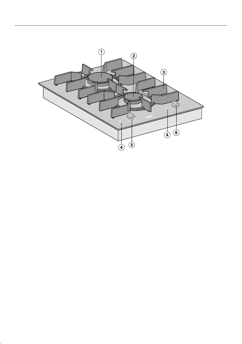
Guide to the appliance
Hob
a
Burner
b
Burner
c
Pot rests
d
Symbols for allocation of operating controls
e
Control for rear burner
f
Control for front burner
18
Page 19
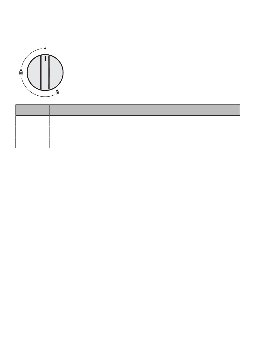
Control knobs
Symbol Description
Burner off, the gas supply is turned off
Largest flame
Smallest flame
Guide to the appliance
19
Page 20
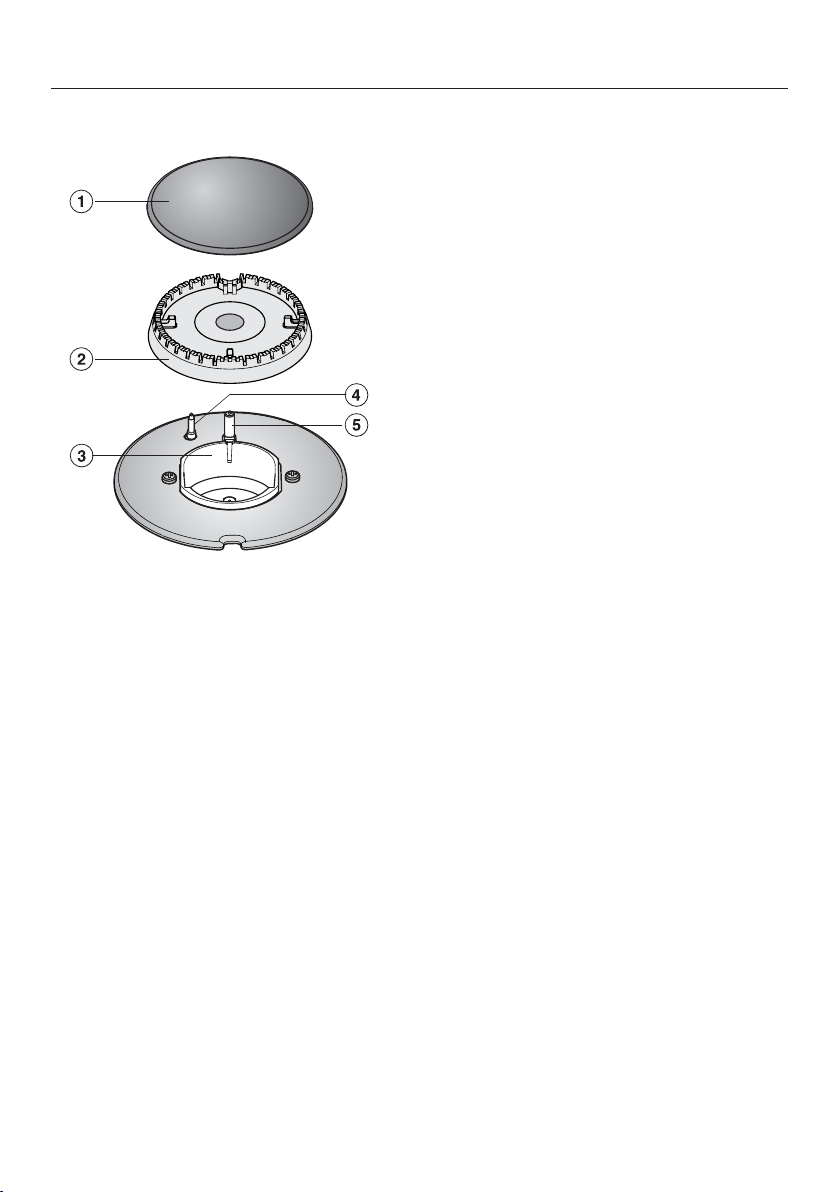
Guide to the appliance
Burner
a
Burner cap
b
Burner head
c
Burner base
d
Thermocouple
e
Ignition electrode
20
Page 21
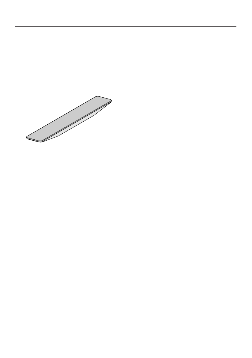
Accessories supplied
The accessories supplied with your
appliance as well as a range of optional
ones are available to order from your
Miele dealer (see „Optional
accessories“).
FlameGuard
For installing between the downdraft
extractor and a gas cooking element
Guide to the appliance
21
Page 22

Before using for the first time
Please stick the extra data plate for
the appliance supplied with this
documentation in the space provided
in the “After sales service” section of
this booklet.
Remove any protective wrapping and
stickers.
Cleaning the SmartLine element for the first time
Clean all removable parts of the
burners with a solution of warm water
and a small amount of washing-up
liquid applied with a soft sponge. Dry
all parts thoroughly after cleaning and
then reassemble the burners (see
“Cleaning and care”).
Clean the ceramic surface with a
damp cloth, and then wipe dry.
Switching on the SmartLine element for the first time
The metal components have a
protective coating. Smells and possibly
some vapours may occur when the
SmartLine element is used for the first
time.
The smell and any vapours given off do
not indicate a faulty connection or
appliance and they are not hazardous
to health.
22
Page 23

Pans
Ø Pan [cm]
Burner Minimum base
diameter
Normal burner 12
Large burner 14
Burner Maximum rim
diameter
Normal burner 22
Large burner 24
- Select the pan to suit the size of the
burner:
large diameter = large burner
small diameter = small burner.
- Observe the dimensions given in the
chart. Using pans that are too large
can cause the flames to spread out
and damage the surrounding worktop
or other appliances. Using pans of
the correct size improves efficiency.
Pans that are smaller than the pot
rests and pans that do not stand
safely (without wobbling) on the pot
rests are dangerous and should not
be used.
- Cookware with a thick base is
preferable as the heat is distributed
evenly. With thinner based cookware,
there is the risk that food will
overheat in places. Therefore it
should be stirred more frequently.
- Always place the cookware on the
pot rests supplied. Do not place
cookware directly on the burners.
- Place the cookware on the pot rests
in such a way that it cannot tip over.
A minor wobble can never be
completely excluded.
- Do not use pots or pans with an
edge-supported base.
- In contrast to pans for use on electric
hobs, the bases of pans for use on
gas hobs do not need to be flat to
achieve good results.
- Remember when purchasing new
pans that manufacturers usually refer
to the diameter at the top of the pan
in their documentation, and not to the
base diameter.
- You can use any cookware that is
heat-resistant.
23
Page 24

Tips on saving energy
- Use a pan lid whenever possible to
minimize heat loss.
- Wide, shallow pans are preferable to
tall, narrow ones. They will heat up
faster.
- Cook with as little water as possible.
- Reduce the size of the flame once the
water has come to the boil or the oil
is hot enough to fry in.
- Use a pressure cooker to reduce
cooking times.
24
Page 25

Operation
Switching on
If you are operating a gas cooking
element next to a downdraft
extractor, this will affect the gas
cooking element's function.
Place the FlameGuard between the
gas cooking element and the
downdraft extractor.
Risk of fire with overheated food.
Unattended food can overheat and
catch alight.
Do not leave the hob unattended
whilst it is being used.
Press in the relevant rotary control
and turn it anticlockwise to the large
flame symbol. The ignition electrode
will “click” and ignite the gas.
When the rotary control is operated, a
spark is automatically produced on all
burners. This is normal and does not
indicate a fault.
When a flame is visible, keep the
rotary control pressed down for 5–
10seconds, and then let it go.
Switching on during a power outage
If there is an interruption to the
electricity supply, the gas can be
ignited manually, e.g. with a match.
Press in the relevant control and turn
it anti-clockwise to the large flame
symbol.
Hold the control pressed in and light
the gas at the burner with a match.
Keep the control pressed in for a
further 5-10seconds and then
release it.
FlameGuard
Install the FlameGuard directly next to
the downdraft extractor when you are
operating a gas cooking element.
If the burner does not ignite, turn the
rotary control to the position.
Ventilate the room or wait for at least
1minute before trying again. When
making another ignition attempt, it
may be necessary to hold the rotary
control for longer.
If the burner does not ignite the
second time, turn the rotary control
back to the position and see
“Problem solving guide”.
25
Page 26

Operation
Adjusting the flame
The burners can be regulated at any
level between the strongest and
weakest flame.
As the outer part of the flame is much
hotter than the centre, the tips of the
flames should stay beneath the pan
base. Flame tips which extend beyond
the sides of the pan merely warm up
the air in the room and can also
damage pan handles and increase the
danger of injury.
Adjust the flame so that it does not
spread out beyond the sides of the
pan.
Switching off
Turn the rotary control clockwise to
the position.
The gas supply is cut off and the flame
goes out.
26
Page 27

Thermo-electric flame failure monitor
Your hob is equipped with a thermoelectric flame failure monitor. If a gas
flame is extinguished, e.g. by food
boiling over or by a draught, the gas
supply is switched off. This prevents the
release of gas. If you turn the rotary
control to the position, the burner is
ready for use again.
The thermo-electric flame failure
monitor operates independently from
the electricity supply. This means that
it will still work if the hob is used
during a power cut.
Safety features
27
Page 28
Cleaning and care
Danger of burning due to hot
surfaces.
The hob surface, pan supports and
burners will be hot after use.
Allow the hob to cool down before
cleaning it.
Risk of damage due to moisture
ingress.
The steam from a steam cleaning
appliance could reach live electrical
components and cause a short
circuit.
Do not use a steam cleaner to clean
the hob.
All surfaces could be discoloured or
damaged if unsuitable cleaning
agents are used. All surfaces are
susceptible to scratching.
Remove all cleaning agent residues
immediately.
Never use abrasive sponges or
cleaning agents.
Clean the SmartLine element and
accessories after each use.
Dry the SmartLine element thoroughly
after every cleaning to avoid
limescale residue.
Unsuitable cleaning agents
To avoid damaging the surfaces of the
appliance, do not use:
- cleaning agents containing soda,
alkalines, ammonia, acids or
chlorides
- cleaning agents containing descaling
agents
- stain and rust removers
- abrasive cleaning agents, e.g.
powder cleaners and cream cleaners
- solvent-based cleaning agents
- dishwasher cleaner
- oven sprays
- glass cleaning agents
Food boiling over can cause
discoloration of the burner
components.
Remove any soiling and salt and
sugar splashes immediately.
When a control knob is pressed
down, a spark is generated on the
ignitor. Do not press down the
control knob while you are cleaning
or touching the hob or a burner in the
vicinity of an ignitor.
Allow the SmartLine element to cool
down before cleaning.
28
- hard, abrasive brushes or sponges
(e.g. pot scourers), or sponges which
have been previously used and still
contain abrasive cleaning agents
- melamine eraser blocks
Page 29

Cleaning and care
Ceramic surface
Risk of damage by pointed
objects.
The seal between the SmartLine
element and the worktop could
suffer damage.
Do not use pointed objects for
cleaning.
Not all soiling and residues can be
removed using a solution of
washing-up liquid.
An invisible film can develop that can
lead to discolouration of the glass
ceramic surface. This discolouration
cannot be removed.
Clean the ceramic surface regularly
with a proprietary ceramic glass
cleaning agent.
Remove any coarse soiling with a
damp cloth and more stubborn
soiling with a shielded scraper blade
suitable for use on glass.
Then clean the ceramic glass surface
with the Miele ceramic and stainless
steel hob cleaner (see “optional
accessories”) or with a proprietary
ceramic glass cleaner applied with
kitchen paper or a clean cloth. Do not
apply the cleaner while the hob is still
hot, as this can result in marking.
Please follow the cleaning agent
manufacturer's instructions.
Residues can burn onto the hob the
next time it is used and cause damage
to the glass ceramic surface. Ensure
that all cleaning agent residues are
removed.
Spots caused by limescale, water
and aluminium residues (spots with a
metallic appearance) can be removed
using Miele's ceramic and stainless
steel hob cleaner.
Danger of burning due to hot
surfaces.
The surfaces get hot during cooking.
Wear oven gloves when removing
residues of sugar, plastic or
aluminium foil from a hot ceramic
surface with a shielded scraper
blade.
Should any sugar, plastic or
aluminium foil spill or fall onto the
hot ceramic surface while it is in use,
switch off the cooking zone.
Then carefully scrape off these
residues immediately whilst they are
still hot, using a scraper blade
suitable for use on glass.
Afterwards, clean the ceramic surface
in its cooled state, as described
above.
Finally wipe the glass ceramic surface
with a damp cloth and polish with a
soft, dry cloth.
29
Page 30

Cleaning and care
Rotary controls
Clean the rotary control(s) using a
solution of warm water and a little
washing-up liquid applied with a soft
sponge. Soften any stubborn soiling
beforehand.
Dry the control(s) with a clean cloth.
Pan supports
Remove the pan supports.
Clean the pan supports in the
dishwasher or with a solution of warm
water and a little washing-up liquid
applied with a soft sponge. Stubborn
soiling should be soaked first.
After cleaning, dry the pan supports
thoroughly with a clean cloth.
30
Page 31

Burner
Do not clean any parts of the burners
in a dishwasher.
The surface of the burner cap will
become duller with time. This is
completely normal and does not
indicate material deterioration.
The burner should be dismantled and
then cleaned by hand using a
solution of warm water and a little
washing-up liquid applied with a soft
sponge.
Clean any soiling from the flame
openings.
Cleaning and care
Danger of explosion.
Blocked flame openings can cause a
dangerous build-up of gas in the
base of the hob which could ignite
and cause an explosion. This can
lead to damage to the appliance and
injury.
Ensure the flame openings are kept
clean at all times.
Parts of the burner that cannot be
removed should be wiped clean with
a damp cloth only.
The ignitor and thermocouple should
be very carefully wiped clean using a
well wrung-out cloth.
The ignitor must not get wet,
otherwise it will not spark.
Finally dry everything thoroughly with
a clean cloth. Make sure that the
flame openings are completely dry.
Place the burner head onto the
burner base so that the
thermocouple and the ignition
electrode extend through their
respective holes in the burner head.
The burner head must click into place
correctly.
Place the burner cap flat over the
burner head. When correctly
positioned, the burner cap will not
slide about.
Ensure that all parts of the burner are
reassembled in the correct order.
31
Page 32

32
Page 33

Problem solving guide
Many malfunctions and faults that can occur in daily operation can be easily
remedied. Time and money will be saved because a service call will not be
needed.
The following guide may help you to find the reason for a malfunction or a fault,
and to correct it.
Issue Cause and remedy
The burners do not
ignite when the hob is
being used for the first
time or after it has been
out of use for a longer
period.
The burner does not
light after several
attempts.
The gas flame goes out
after ignition.
The flame suddenly
looks different.
There could be an air lock in the gas pipe.
You may need to make several attempts before the
burner ignites successfully.
There is a technical fault.
Turn all of the controls clockwise to the position
and interrupt the power supply to the hob for a few
seconds.
The burner is not correctly assembled.
Assemble the burner correctly.
The gas shut-off device has not been opened.
Open the gas shut-off device.
The burner is wet and/or dirty.
Clean and dry the burner.
The flame openings are blocked and/or wet.
Clean and dry the flame openings.
The flames do not touch the thermocouple and the
burner does not get hot enough:
The burner parts are not positioned correctly.
Assemble the burner components correctly.
The thermocouple is dirty.
Remove any soiling.
The burner parts are not positioned correctly.
Position the burner parts correctly.
The burner head or the holes in the burner cap are
dirty.
Remove any soiling.
33
Page 34

Problem solving guide
Issue Cause and remedy
The gas flame goes out
during use.
The electronic ignition
device on the burner is
not working.
The burner parts are not positioned correctly.
Position the burner parts correctly.
The mains fuse has tripped.
If necessary, contact a qualified electrician or your
Miele dealer for assistance.
There is food residue stuck between the ignitor and
the burner cap.
The thermocouple is dirty.
Remove any soiling (See “Cleaning and care”).
34
Page 35

Optional accessories
Miele offer a comprehensive range of
useful accessories as well as cleaning
and conditioning products for your
Miele appliances.
These can be ordered from your Miele
dealer (see end of this booklet for
contact details).
FlameGuard
For installing between the downdraft
extractor and a gas cooking element
Ceramic and stainless steel
hob cleaner 250ml
Removes heavy soiling, limescale
deposits and aluminium residues
Microfibre cloth
Removes finger marks and light soiling
35
Page 36

After sales service
Contact in case of malfunction
In the event of any faults which you cannot remedy yourself, please contact your
Miele dealer.
Contact details for your Miele dealer are given at the end of this document.
Please note that telephone calls may be monitored and recorded for training
purposes and that a call-out charge will be applied to service visits where the
problem could have been resolved as described in this booklet.
Please quote the model and serial number of your appliance when contacting your
Miele dealer. This information can be found on the data plate.
Data plate
Stick the extra data plate supplied with the appliance here. Make sure that the
model number matches the one specified on the back cover of this document.
Guarantee
For information on the appliance guarantee specific to your country please contact
your Miele dealer. See end of this booklet for contact details.
36
Page 37

*INSTALLATION*
Installation
Safety instructions for installation
Damage from falling objects.
Take care not to damage the SmartLine element when fitting wall units or a
cooker hood above it.
Fit the wall units and the cooker hood before the SmartLine element.
The room in which the SmartLine element is installed must
conform to all relevant local and national building regulations and
safety regulations.
In the UK: GasSafe regulations
The veneer or laminate coatings of worktops (or adjacent kitchen
units) must be treated with 100°C heat-resistant adhesive which will
not dissolve or distort. Any backmoulds must be of heat-resistant
material.
A deep fat fryer must not be installed directly next to a gas hob or
a wok burner as the gas flames could ignite the fat in the fryer. It is
essential to maintain a distance of at least 288mm between these
two appliances.
The SmartLine element must not be installed over a fridge, fridge-
freezer, freezer, dishwasher, washing machine, washer-dryer or
tumble dryer.
When installing the SmartLine element, make sure that the gas
pipe and mains connection cable cannot come into contact with hot
appliance parts.
The mains connection cable and any flexible gas connection pipes
must be installed in such a way so that they do not come into
contact with any moving kitchen parts (e.g. a drawer) after the
SmartLine element has been installed, and that they cannot be
subjected to any mechanical action which could cause damage.
Observe carefully the safety clearances listed on the following
pages.
37
Page 38

*INSTALLATION*
Installation
Safety distances
Safety distance above the SmartLine element
The safety distance specified by the
manufacturer of the cooker hood must
be maintained between the SmartLine
element and the cooker hood above it.
If combustible objects are installed
above the SmartLine element (e.g.
cabinets, utensil rail, etc.), a minimum
safety distance of 760mm must be
maintained.
When two or more SmartLine
elements which have different safety
distances are installed together
below a cooker hood, you should
observe the greatest specified safety
distance.
38
Page 39

*INSTALLATION*
Safety distances to the sides and back of the hob
The SmartLine element should
preferably be installed with plenty of
space on the right and left.
The minimum distance specified
below must be observed between the
rear of the SmartLine element and a tall
unit or room wall.
The minimum distance, specified
below must be adhered to between one
side of the SmartLine element (right or
left) and a tall unit or room wall. A
minimum distance of 300mm must be
observed on the opposite side.
Minimum distance between the back
of the worktop cut-out and the rear
edge of the worktop:
50mm
Installation
Not allowed
Highly recommended
Minimum distance on the right side
between the worktop cut-out and the
closest adjacent piece of furniture (e.g.
tall unit) or a room wall:
100mm.
Minimum distance on the left side
between the worktop cut-out and the
closest adjacent piece of furniture (e.g.
tall unit) or a room wall:
100mm.
Not recommended
Not recommended
39
Page 40

*INSTALLATION*
Installation
Safety distance when installing the appliance near a wall with additional niche cladding
If a niche cladding is installed, a minimum safety distance must be maintained
between the worktop cut-out and the cladding, since high temperatures can
damage these materials.
If the niche cladding is made from a combustible material (e.g. wood) a minimum
safety distance of 50mm must be maintained between the worktop cut-out and
the cladding.
If the niche cladding is made from a non-combustible material (e.g. metal, natural
stone, ceramic tiles) the minimum safety distance between the worktop cut-out
and the cladding will be 50mm less the thickness of the cladding.
Example: 15mm niche cladding
50mm - 15mm = minimum safety distance of 35mm
Flush-fit installation Onset installation
a
Masonry
b
Niche cladding dimension x = thickness of the niche cladding material
c
Worktop
d
Worktop cut-out
e
Minimum distance to
combustible materials 50mm
non-combustible materials 50mm - dimension x
40
Page 41

*INSTALLATION*
Installation
Surface-mounted
Installation notes – surface-mounted
Sealing between the SmartLine Element and the worktop
The SmartLine element and worktop
may be damaged if the element
needs to be removed after it has
been sealed with a sealant.
Do not use any sealant between the
SmartLine element and the worktop.
The seal under the edge of the top
part of the appliance provides a
sufficient seal for the worktop.
Tiled worktop
Grout lines and the hatched area
underneath the SmartLine element
frame must be smooth and even. If they
are not, the SmartLine element will not
sit flush with the worktop and the
sealing strip underneath the top part of
the appliance will not provide a good
seal between the appliance and the
worktop.
Sealing strip
Dismantling the SmartLine element
for service purposes may damage
the sealing strip underneath the edge
of the SmartLine element.
Always replace the sealing strip
before reinstalling the SmartLine
element.
41
Page 42

*INSTALLATION*
Installation
Installing several SmartLine elements
The gaps between the individual
SmartLine elements are sealed with a
silicone sealant that is heat-resistant to
at least 160°C. With flush-fit
installation, the gap between the
SmartLine element(s) and the worktop
must also be sealed with a silicone
sealant that is heat-resistant to at least
160°C.
After installation, the SmartLine
elements must be easily accessible
from below, so that the bottom half of
the casing can be removed for
maintenance. If the SmartLine elements
are not accessible from below, the
sealant must be removed so that they
can be removed.
Combination with a downdraft extractor
If the SmartLine element is installed in
combination with a downdraft extractor,
the latter must be installed first.
42
Page 43

*INSTALLATION*
Worktop cutout – surface-mounted
Installation
Information for calculating the cutout
The elements overlap the worktop by 10mm.
When installing several elements, a distance of 2mm must be observed between
the individual elements.
Calculating cutout dimensionB
1 element = Width of the element minus 10mm on the right, minus 10mm on the
left
Several elements = Total width of the elements plus 2mm distance between the
elements, minus 10mm on the right, minus 10mm on the left.
Some examples are illustrated below.
43
Page 44

*INSTALLATION*
Installation
Installation with a downdraft extractor
Combination examples Numberxwidth [mm] Dimension
Cooking
elements
Downdraft
extractor
1x378 1x120
B
[mm]
480
+1
2x378 1x120
1x378
2x120
1x620
3x378 2x120
2x378
2x120
1x620
4x378 2x120
1x620 2x120
860
1224
1362
1604
1742
844
+1
+1
+1
+1
+1
+1
44
Page 45

*INSTALLATION*
Installation without a downdraft extractor
Combination examples Numberxwidth [mm] DimensionB
Cooking elements
1x378
Installation
[mm]
+1
358
2x378
1x378
1x620
3x378
2x378
1x620
4x378
738
980
1118
1360
1498
+1
+1
+1
+1
+1
45
Page 46

*INSTALLATION*
Installation
Spacer bars – surface-mounted
When installing several SmartLine elements, an additional spacer bar must be
fitted in between the individual elements.
The clips supplied with the spacer bars are only required for installing a
CSDA700xFL.
Installing 3elements and 2spacer bars
46
Page 47

*INSTALLATION*
Installation dimensions–Surface-mounted
All dimensions are given in mm.
Installation
a
Front
b
Mains connection box with mains connection cable, L=2000mm
c
Gas connection R½ ISO7-1 (DINEN10226)
47
Page 48

*INSTALLATION*
Installation
Installation – surface-mounted
Preparing the worktop
Create the worktop cutout.
Remember to maintain the minimum
safety distances (see “Installation –
Safety distances”).
Seal any cut surfaces on wooden
worktops with a special varnish,
silicone sealant or resin to prevent the
wood from swelling as a result of
moisture ingress. The sealant must
be heat-resistant.
Make sure that the sealant does not
come into contact with the top of the
worktop.
Fitting the spacer bars
Use the middle screw holes if one of the
following SmartLine elements is
installed to the right or left of the spacer
bar: CS7611, CS 7641, CS7101(-1),
CS7102(-1)
Wooden worktops
Position the spacer bars flush onto
the upper edge of the cutout.
Secure the spacer bars with the
3.5x25mm wood screws supplied.
Natural stone worktops
You will need heavy-duty doublesided tape (not supplied) to secure the
spacer bars.
48
Stick the tape along the top edge of
the worktop cutout.
Position the spacer bars flush onto
the upper edge of the cutout.
Press the spacer bars firmly into
place.
Page 49

*INSTALLATION*
Installation
Installing the SmartLine element
Stick the supplied sealing strip under
the edge of the SmartLine element.
Do not apply the sealing strip under
tension.
Feed the mains connection cable
down through the worktop cutout.
Position the SmartLine element in the
worktop cutout. When doing this,
make sure that the seal of the
appliance sits flush with the worktop
on all sides. This is important to
ensure an effective seal all round.
If the seal does not meet the worktop
correctly on the corners, carefully
scribe the corner radii (≤R4) with a
jigsaw.
Do not use any additional sealant
(e.g. silicone) on the SmartLine
element.
Connect the SmartLine element to
the mains electricity supply.
Checking operation
After installation, ignite all burners to
check that they are operating
correctly:
- The flame must not go out on the
lowest setting, or when the control is
turned quickly from the highest to the
lowest setting.
- On the highest setting, the flame
must have a distinctive and visible
core.
If required, connect the SmartLine
element to the gas supply (see
“Installation – Gas connection”).
Check that the SmartLine element
works.
Seal the gaps between the individual
elements with a silicone sealant that
is heat-resistant to at least 160°C.
Unsuitable sealant can damage
natural stone.
For natural stone worktops and
natural stone tiles, only use silicone
sealant that is specially formulated
for natural stone. Follow the
manufacturer’s instructions.
49
Page 50

*INSTALLATION*
Installation
Flush-fit
Installation notes – flush-fit
Flush-fit installation is only possible in
natural stone (granite, marble), solid
wood and tiled worktops. For
installation in worktops made of other
materials, please consult the relevant
manufacturer as to whether their
worktops are suitable for flush-fit
installation.
The internal width of the base unit
underneath the appliance must be at
least as wide as the inner worktop
cutout (see “Installation – Building-in
dimensions – flush-fit”), so that the
SmartLine element is easily accessible
from underneath after installation and
the bottom half of the casing can be
removed for maintenance. If the
element is not freely accessible from
below after installation, the sealant
must be removed so that the element
can be removed.
Natural stone worktops
The SmartLine element is set directly in
the cutout.
Solid wood worktops, tiled worktops,
glass worktops
The SmartLine element is set on a
wooden frame inside the cutout. The
frame must be provided on site, and is
not supplied with the appliance.
Sealing strip
Dismantling the SmartLine element
for service purposes may damage
the sealing strip underneath the edge
of the SmartLine element.
Always replace the sealing strip
before reinstalling the SmartLine
element.
50
Page 51

*INSTALLATION*
Installing several SmartLine elements
The gaps between the individual
SmartLine elements are sealed with a
silicone sealant that is heat-resistant to
at least 160°C. With flush-fit
installation, the gap between the
SmartLine element(s) and the worktop
must also be sealed with a silicone
sealant that is heat-resistant to at least
160°C.
After installation, the SmartLine
elements must be easily accessible
from below, so that the bottom half of
the casing can be removed for
maintenance. If the SmartLine elements
are not accessible from below, the
sealant must be removed so that they
can be removed.
Installation
Combination with a downdraft extractor
If the SmartLine element is installed in
combination with a downdraft extractor,
the latter must be installed first.
51
Page 52

*INSTALLATION*
Installation
Worktop cutout – flush-fit
Natural stone worktop Wooden worktop
0.5
+
* 7
mm with CS7611FL
Information for calculating the cutout
The elements overlap the worktop by 10mm.
When installing several elements, a distance of 2mm must be observed between
the individual elements.
Calculating cutout dimensionA
1 element = Width of the element plus 2mm on the right, plus 2mm on the left.
Several elements = Total width of the elements plus 2mm distance between the
elements, plus 2mm on the right, plus 2mm on the left
Calculating cutout dimensionB = Cutout dimension A minus 12mm on the right,
minus 12mm on the left.
Some examples are illustrated below.
52
Page 53

*INSTALLATION*
Installation with a downdraft extractor
Installation
Combination examples Numberxwidth [mm] Dimensi
Cooking
elements
Downdraft
extractor
1x378 1x120
2x378 1x120
1x378
2x120
onA
[mm]
504
884
1248
+1
+1
+1
1x620
3x378 2x120
2x378
2x120
1386
1628
+1
+1
1x620
4x378 2x120
1x620 2x120
1766
868
+1
+1
Dimensi
onB
[mm]
+1
480
+1
860
+1
1224
+1
1362
+1
1604
+1
1742
+1
844
53
Page 54

*INSTALLATION*
Installation
Installation without a downdraft extractor
Combination
examples
Numberxwidth
[mm]
Cooking elements
1x378
2x378
1x378
1x620
3x378
2x378
1x620
4x378
DimensionA
[mm]
+1
382
+1
762
+1
1004
+1
1142
+1
1384
+1
1522
DimensionB
[mm]
+1
358
+1
738
+1
980
+1
1118
+1
1360
+1
1498
54
Page 55

*INSTALLATION*
Spacer bars – flush-fit
When installing several SmartLine elements, an additional spacer bar must be
fitted in between the individual elements.
The clips supplied with the spacer bars are only required for installing a
CSDA700xFL.
Installing 3elements and 2spacer bars
Installation
55
Page 56

*INSTALLATION*
Installation
Installation dimensions–Flush
All dimensions are given in mm.
a
Front
b
Mains connection box with mains connection cable, L=2000mm
c
Stepped cutout (for detailed illustrations, see “Installation – Worktop cutout –
flush-fit”)
d
12mm wooden frame (not supplied, for detailed illustrations, see “Installation –
Worktop cutout – flush-fit”)
e
Gas connection R½ ISO7-1 (DINEN10226)
56
Page 57

*INSTALLATION*
Installation
Installation – flush-fit
Preparing the worktop
Create the worktop cutout.
Remember to maintain the minimum
safety distances (see “Installation –
Safety distances”).
Seal any cut surfaces on wooden
worktops with a special varnish,
silicone sealant or resin to prevent the
wood from swelling as a result of
moisture ingress. The sealant must
be heat-resistant.
Make sure that the sealant does not
come into contact with the top of the
worktop.
For wooden worktops, secure the
wooden frame 5.5mm below the
upper edge of the worktop.
For CS7611FL, the wooden frame
must be secured 7mm under the
upper edge of the worktop.
Wooden worktops
Position the spacer bars flush onto
the lower step of the stepped cutout.
Secure the spacer bars with the
3.5x25mm wood screws supplied.
Natural stone worktops
You will need heavy-duty doublesided tape (not supplied) to secure the
spacer bars.
Fitting the spacer bars
Use the middle screw holes if one of the
following SmartLine elements is
installed to the right or left of the spacer
bar: CS7611, CS 7641, CS7101(-1),
CS7102(-1)
Stick the tape onto the lower step of
the stepped cutout.
Position the spacer bars flush onto
the lower step of the stepped cutout.
Press the spacer bars firmly into
place.
57
Page 58

*INSTALLATION*
Installation
Installing the SmartLine element
Stick the supplied sealing strip under
the edge of the SmartLine element.
Do not apply the sealing strip under
tension.
Feed the mains connection cable
down through the worktop cutout.
Position the SmartLine element in the
worktop cutout. When doing this,
make sure that the seal of the
appliance sits flush with the worktop
on all sides. This is important to
ensure an effective seal all round.
Connect the SmartLine element to
the mains electricity supply.
If required, connect the SmartLine
element to the gas supply (see
“Installation – Gas connection”).
Check that the SmartLine element
works.
Seal the gaps between the individual
elements and between the elements
and the worktop with a silicone
sealant that is heat-resistant to at
least 160°C.
Checking operation
After installation, ignite all burners to
check that they are operating
correctly:
- The flame must not go out on the
lowest setting, or when the control is
turned quickly from the highest to the
lowest setting.
- On the highest setting, the flame
must have a distinctive and visible
core.
Unsuitable sealant can damage
natural stone.
For natural stone worktops and
natural stone tiles, only use silicone
sealant that is specially formulated
for natural stone. Follow the
manufacturer’s instructions.
58
Page 59

*INSTALLATION*
Installation
Gas connection
Risk of explosion due to an
incorrect gas connection.
If the gas connection is carried out
incorrectly, it may result in gas
leakage.
Connection to the gas supply must
only be undertaken by an approved
and registered gas installer in strict
accordance with current local and
national safety and building
regulations. The installer is
responsible for ensuring that the
appliance functions correctly when
installed.
Risk of explosion due to an
incorrect conversion.
If the conversion to another type of
gas is carried out incorrectly, it may
result in gas leakage.
Conversion from one type of gas to
another must only be undertaken by
an approved and registered gas
installer in strict accordance with
current local and national safety and
building regulations. The installer is
responsible for ensuring that the
appliance functions correctly when
installed.
The gas connection must be
installed so that connection can be
made either from inside or outside
the kitchen furniture unit. The
isolating valve must be easily
accessible and visible (by opening
the cabinet door if necessary).
Check with your local gas supplier
about the type of gas supplied and
compare this information with the
type of gas quoted on the
appliance's data plate.
The hob is not connected to an
exhaust flue.
When installing and connecting the
appliance please observe all relevant
installation instructions and ensure it
has adequate ventilation once
installed.
The gas connection must be made in
accordance with national and local
regulations.
Any special local conditions relating
to gas installations as well as
building regulations must also be
observed.
Risk of heat damage.
Gas connections, pipes and
connection cables can suffer
damage if exposed to heat from the
hob.
After installation make sure that
neither the gas pipe nor the mains
cable can come into contact with hot
parts of the appliance and that the
gas pipe and connections on the hob
cannot come into contact with hot
gas exhaust.
59
Page 60

*INSTALLATION*
Installation
Risk of explosion due to
damaged gas pipes.
Gas can leak from damaged flexible
gas pipes.
Attach flexible gas pipes in such a
way so that they do not come into
contact with any moving kitchen
parts (e.g. a drawer) and are not
exposed to mechanical stress.
Connect the hob to the gas supply in
accordance with national and local
regulations. Check the gas
connection for any leaks.
Depending on country of destination
this appliance is set up for connection
to natural or liquid gas. See adhesive
label on the appliance.
Depending on country of destination,
jets are supplied for conversion to a
different type of gas. If the appropriate
jets have not been supplied with the
appliance, you will need to contact your
Miele dealer. Conversion to another
type of gas is described in the section
“Converting to another type of gas”.
Connecting the hob
The hob is supplied with a conical ¹/₂"
gas connection point. There are two
connection options:
Risk of explosion due to gas
leakage.
Unsuitable sealant will not ensure the
required leak protection for
connections.
Ensure that a suitable sealant is
used.
Using a 90° angle
c
Connection R¹/₂"
d
90° elbow
The installation height in the area of
the gas connection is increased by
approx. 60mm.
- Fixed connection
- Flexible connection in accordance
with DIN 3383 Part 1, maximum
length 2000 mm.
60
Page 61

*INSTALLATION*
Installation
Electrical connection
We recommend that you connect the
SmartLine element to the mains via a
suitable switched electrical socket. This
makes it easier to perform servicing
work. The socket must be easily
accessible after the SmartLine element
has been installed.
Danger of injury!
Installation, repairs and other work
by unqualified persons could be
dangerous. Miele cannot be held
liable for unauthorised work.
Miele cannot be held liable for
damage or injury caused by the lack
of or inadequacy of an on-site
earthing system (e.g. electric shock).
If the plug is removed from the
connection cable or if the cable is
supplied without a plug, the
SmartLine element must be
connected to the electrical supply by
a suitably qualified electrician.
If the socket is no longer accessible,
or if a hard-wired connection is
planned, an additional means of
disconnection must be provided for
all poles. Suitable means of
disconnection include switches with
an all-pole contact gap of at least
3mm. These include miniature circuit
breakers, fuses and contactors. The
required connection data is given on
the data plate. Please ensure this
information matches the mains
supply.
After installation, ensure that all
electrical components are shielded
and cannot be accessed by users.
Total power rating
See data plate
Connection data
The connection data is quoted on the
data plate. Please ensure these match
the household mains supply.
Residual current device
For extra safety, it is advisable to
protect the SmartLine element with a
suitable residual current device (RCD)
with a trip range of 30mA.
61
Page 62

*INSTALLATION*
Installation
Disconnecting from the mains
Risk of electric shock.
There is a risk of electric shock if the
appliance is connected to the mains
supply during repair or service work.
After disconnection, ensure the
appliance cannot be switched back
on by mistake.
To disconnect the appliance from the
mains power supply, do one of the
following depending on installation:
Safety fuses
Completely remove fuses.
Automatic circuit breakers
Press the (red) test button until the
middle (black) button springs out.
Built-in circuit breakers
Circuit breakers at least type B or C:
Switch the lever from 1 (on) to 0 (off).
Connecting the mains cable
Danger of electrical shock.
The mains connection cable must
only be fitted by a suitably qualified
and competent person.
If the mains cable needs to be replaced
it must be replaced with a special
connection cable, type H05VV-F (PVCinsulated), available from your Miele
dealer.
Residual current device (RCD)
Switch the main switch from 1 (on) to
0 (off) or press the test button.
62
Page 63

Burner ratings
Nominal ratings
Burner Gas type Highest setting Lowest
setting
kW g/h kW
Medium burner Natural gas H 1.7 – 0.3
Liquid gas 1.7 124 0.25
Large burner Natural gas H 2.7 – 0.5
Liquid gas 2.6 189 0.6
Total Natural gas H 4.4 – –
Liquid gas 4.3 313 –
63
Page 64

*INSTALLATION*
Converting to another gas type
Risk of explosion due to an
incorrect conversion.
If the conversion to another type of
gas is carried out incorrectly, it may
result in gas leakage.
Conversion from one type of gas to
another must only be undertaken by
an approved and registered gas
installer in strict accordance with
current local and national safety and
building regulations. The installer is
responsible for ensuring that the
appliance functions correctly when
installed.
Jet table
The jet markings refer to a ¹/₁₀₀mm
bore diameter.
Main jet Small jet
Natural gas H
Medium burner 0.94 0.42
Large burner 1.18 0.54
Liquid gas
Medium burner 0.66 0.23
Large burner 0.81 0.39
Changing the main jets
Remove the pot rest, burner cap
and burner head.
Using an M7 socket spanner,
unscrew the main jet.
Fit the correct jets securely (see jet
table).
Secure the jets against inadvertent
loosening with sealing wax.
Changing the jets
Disconnect the hob from the
electricity supply and turn off the gas
supply.
When converting to another type of
gas, both the main and small jets
need to be changed.
64
Page 65

*INSTALLATION*
a
b
Converting to another gas type
Changing the small jets
Remove the burner components.
Loosen the fixing screws on the
burners.
Pull the control knobs off.
Loosen the fixing nuts on the
underside of the appliance.
Carefully remove the underside of the
appliance.
Functional check
Check all gas fittings for leaks.
Reassemble the hob.
Ignite all burners to check that they
are operating correctly.
- The flame must not go out on the
lowest setting, or when the control is
turned quickly from the highest to the
lowest setting.
- On the highest setting, the flame
must have a distinctive and visible
core.
Adhere the label supplied with the
jets, stating the type of gas being
used.
Remove the ignition switch.
Using a small screwdriver, unscrew
the small jet in the gas fitting.
Pull out the jet with a pair of pliers.
Fit the correct jets securely (see jet
table).
Secure the jets against inadvertent
loosening with sealing wax.
65
Page 66

Page 67

Manufacturer:
Miele & Cie. KG, Carl-Miele-Straße 29, 33332 Gütersloh, Germany
Miele Saudi Arabia
AWAD BADI NAHAS TRADING CO. LTD
Head Office:
Jeddah
Miele United Arab Emirates
Miele Appliances Ltd.
Showroom 1
Eiffel 1 Building
Sheikh Zayed Road, Umm Al Sheif
P.O. Box 114782 - Dubai
United Arab Emirates
Tel. +971 4 3044 999
Fax. +971 4 3418 852
800-MIELE (64353)
E-Mail: info@miele.ae
Website: www.miele.ae
Webshop: shop.miele.ae
Taif
Riyadh
Branches:
Khobar
Jeddah
Jeddah
Jeddah
P.O. Box 11529 Jeddah 21463
Tel. +966 12 2560888, Fax. +966 12 2560555
Hotline for customer care: 920003240
Website: www.awadnahas.com
Madina Road
Tel. +966 12 6970060, Fax. +966 12 6970012
Sitteen Street
Tel. +966 12 6611675, Fax. +966 12 6606852
Miele Gallery
Al Thanyyan Group Building, Al-Madina Road,
Near, Al Rowdah District, Jeddah
Tel. +966 12 6989339 Ext. 100
Fax. +966 12 6989339 Ext. 200
Olaya Street
Tel. +966 11 2013501, Fax. +966 11 2013502
Hadiya Street
Tel. +966 12 7327001, Fax. +966 12 7369596
Al Zahran Road
Tel. +966 13 8646150, Fax. +966 13 8646190
Page 68

CS7102-1
M.-Nr. 11 507 780 / 01en-AE, SA
 Loading...