

Produktgruppe 522 Umbau- und Montageanweisung
1 von 26 M.-Nr. 07724430
06.07.2010 Diese Unterlagen dürfen ohne unsere Genehmigung weder vervielfältigt noch Dritten zugänglich gemacht werden. Eigentumsrechte vorbehalten.
PT 8251, PT 8331, PT 8253, PT 8333
x
de
ni
Montageanweisung
Modul BSK 15
Kassiergeräteanschluss
Montage-instructie moduul
BSK 15 aansluiting
muntautomaat
en
da
Fitting instructions Module BSK 15 - Payment
system connection
Monteringsanvisning modul
BSK 15 betalingssystemtilslutning
fr
no
Notice de montage module
BSK 15 raccordement
monnayeur
Monteringsveiledning for modul
BSK 15 - tilkobling av
betalingsautomat
sv
el
Monteringsanvisning modul
BSK 15 anslutning betal-/
bokningssystem
Οδηγία τοποθέτησης μονάδας
BSK 15 σύνδεση με
κερματοδέκτη
it
am
Istruzioni di montaggio modulo
BSK 15 allacciamento
gettoniera
BSK 15 Module (Coin/Bill
Acceptor) Installation
Instructions
es
Instrucciones de montaje del
módulo BSK 15 para la
conexión aparato recaudador
1
Produktgruppe 522 Umbau- und Montageanweisung
2 von 26 M.-Nr. 07724430
06.07.2010 Diese Unterlagen dürfen ohne unsere Genehmigung weder vervielfältigt noch Dritten zugänglich gemacht werden. Eigentumsrechte vorbehalten.
x

Produktgruppe 522 Umbau- und Montageanweisung
3 von 26 M.-Nr. 07724430
06.07.2010 Diese Unterlagen dürfen ohne unsere Genehmigung weder vervielfältigt noch Dritten zugänglich gemacht werden. Eigentumsrechte vorbehalten.
de
Benötigte Teile
x
Anzahl M.-Nr. Benennung
1 07741560
Hinweis
Diese Umbauarbeiten dürfen grundsätzlich nur von einer Elektrofachkraft (fachliche Ausbildung, Fachkenntnisse und
Facherfahrungen, zeitnahe berufliche Tätigkeit) unter Berücksichtigung der gültigen Sicherheitsbestimmungen
durchgeführt werden.
Für die Instandsetzung, Änderung, Prüfung und Wartung elektrischer Geräte sind die entsprechenden gesetzlichen
Grundlagen, Unfallverhütungsvorschriften, die gültigen Normen, die der Sicherheit dienen, sowie die am Aufstellungsort
gültigen Vorschriften der Energieversorgungsunternehmen zu beachten.
Gefahr!
Auch bei ausgeschaltetem Gerät kann Netzspannung an Bauteilen anliegen!
Deshalb ist, bevor Wartungs-, Instandsetzungs- und Umbauarbeiten am Gerät durchgeführt werden, eine sichere
Netztrennung von allen aktiven, spannungsführenden Leitungen sowie anschließend eine Messung der
Spannungsfreiheit erforderlich!
Grundsätzlich muss eine allgemeine Sichtprüfung durchgeführt werden.
Ein nicht fachgerechter Umbau kann zu einer Gefährdung führen (Brand, elektrischer Schlag usw.).
Umbausatz BSK 15 Kassiergeräteanschluss PT 8251, PT 8331,
PT 8253, PT 8333
Gefahr!
Die Schutzleiterfunktion kann durch einen fehlerhaften Gehäusezusammenbau außer Kraft gesetzt werden.
Die Schutzleiterfunktion ist bei Montage der Gehäuseteile wieder herzustellen.
Elektrische Sicherheitsprüfung durchführen.
Hinweis
Der Montagesatz M.-Nr. 07741560 für PT 8251, PT 8331, PT 8253, PT 8333 enthält:
• 1 Kabelbaum 27X-X1/1
• 1 Kabelzugentlastung
• Diese Montageanweisung “Montageanweisung Modul BSK 15 Kassiergeräteanschluss”, M.-Nr. 07724430
Liste der Abbildungen:
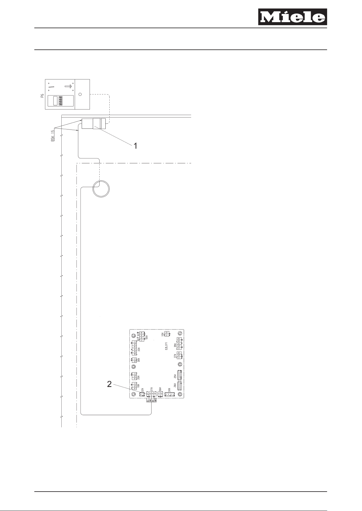
– Abb. 1, Kabelbaum Kassiergeräteanschluss
– Die Maschine vom Elektronetz trennen und gegen Wiedereinschalten sichern.
– Gerätedeckel abbauen.
– Abdeckblech Elektroanschluss an der Rückseite der Maschine abbauen.
x
bl br gn ge gr or rs rt sw vi ws
blau braun grün gelb grau orange rosa rot schwarz violett weiß
Tabelle 1: Kabelfarben
Achtung!
Last- und Steuerstrom Kabelbäume sind getrennt voneinander zu verlegen, um Störsignale in den Steuerleitungen zu
vermeiden (Elektromagnetische Verträglichkeit).

Produktgruppe 522 Umbau- und Montageanweisung
4 von 26 M.-Nr. 07724430
06.07.2010 Diese Unterlagen dürfen ohne unsere Genehmigung weder vervielfältigt noch Dritten zugänglich gemacht werden. Eigentumsrechte vorbehalten.
x
Achtung!
Überschüssige Kabellängen gegenläufig verlegen, um Antennenwirkung bei Leitungen zu vermeiden.
– Kabelbaum 27X-X1/1auf dem Geräteträger durch die Kabeldurchführung in den Bereich des Elektroanschlusses
verlegen, siehe Abb. 1, Pos. 1.
– Kabelbaum 27X-X1/1 in die Steckerwanne EZL 371 – 27X stecken, siehe Abb. 1, Pos. 2.
– Die Kabelzugentlastung für Kassiergeräte an der Verbindungsleiste (Geräterückwand) losschrauben.
– Das Kabel des externen Kassiergerätes in die Maschine einführen und mit der Kabelzugentlastung an der
Verbindungsleiste (Geräterückwand) festschrauben.
– Externes Kassiergerät an der Steckverbindung X1/1 anschließen.
Kassiergerät anmelden:
– Den Stecker NTC aus der Steckerwanne EZL 371 – 10X ziehen, siehe Schaltplan.
– Die Maschine am Elektronetz anschließen.
– Taste “Start/Stop” drücken und halten.
– Gerät durch Drücken des Netz Ein/Aus Schalters einschalten.
– Taste “Start/Stop” loslassen und 4-mal kurz drücken und lösen.
– Anschließend Taste “Start/Stop” drücken und für mindestens 4 Sekunden gedrückt halten.
– Als Quittierungsanzeige blinkt die Ringbeleuchtung der Taste “Start/Stop” schnell (5Hz).
– Nach Aufblinken der Ringbeleuchtung der Taste “Start/Stop” diese Taste lösen.
x
Hinweis
Programmierfunktion wählen:
Taste Schonen/Temperaturanwahl drücken.
Die Programmierfunktion wird durch den Blinkrhythmus der LED Schonen/Temperaturanwahl (neben der Taste Schonen/
Temperaturanwahl) angezeigt.
Option wählen:
Taste Start/Stop drücken.
Die eingestellte Option wird über die Siebensegmentanzeige angezeigt.
Siebensegmentanzeige: ”P” und die Ziffer bzw. Ziffern der gewählten Option werden abwechselnd angezeigt. Zur
Anzeige wird nur das rechte Segment verwendet.
– Taste Schonen/Temperaturanwahl 40 mal kurz hintereinander drücken um die Programmierfunktion Münzfunktion
(Programmierfunktion 41) anzuwählen.
– LED Schonen/Temperaturanwahl blinkt 4 mal lang und 1 mal kurz.
– Taste Start/Stop drücken bis die gwünschte Option über die Siebensegmentanzeige angezeigt wird.
P 0 = keine Münzfunktion
P 1 = C 4060, C 4065, C 4070, C 4080 (Programmfreigabe)
P 2 = C 4065, C 4070, C 4080 (Zeitfreigabe)
P 3 = seriell (nur mit dem Kommunikationsmodul RS232)
– Speichern der ausgewählen Programmierfunktion durch Ausschalten der Maschine über den Netz Ein/Aus Schalter.
– Den Stecker NTC in die Steckerwanne EZL 371 – 10X stecken, siehe Schaltplan.
– Abdeckblech Elektroanschluss an der Rückseite der Maschine anbauen.
– Gerätedeckel anbauen.
– Probelauf durchführen.
– Elektrische Sicherheitsprüfung durchführen.
de
Produktgruppe 522 Umbau- und Montageanweisung
5 von 26 M.-Nr. 07724430
06.07.2010 Diese Unterlagen dürfen ohne unsere Genehmigung weder vervielfältigt noch Dritten zugänglich gemacht werden. Eigentumsrechte vorbehalten.
en
Parts required
x
Quantity Mat. no. Designation
1 07741560
Note
This service and repair work should only be carried out by a suitably qualified electrician (with specialist training,
knowledge and experience, and recent related work experience) in accordance with all appropriate local and national
safety regulations.
Servicing, modification, testing and maintenance of electrical appliances should only be carried out in accordance
with all appropriate legal requirements, accident prevention regulations and valid standards. All regulations of the
appropriate utility supply companies and standards relating to safety (not limited to electrical safety) are to be complied
with.
Conversion kit BSK 15 - Payment system connection - PT 8251,
PT 8331, PT 8253, PT 8333
Danger!
Even with the machine switched off, mains voltage may be applied to some components.
Before any service work is commenced, the machine must be disconnected from the mains. Suitable measurements must
be made to ensure that this is the case.
A general visual check should always be carried out.
Incorrect conversion or service work can be dangerous (risk of fire, electric shock, etc.).
Danger!
Correct earthing function can be deactivated if casing parts are incorrectly assembled.
Correct earthing function must be ensured when refitting the casing.
Carry out appropriate electrical safety checks.
Note
The conversion kit Mat. no. 07741560 for PT 8251, PT 8331, PT 8253, PT 8333 contains the following:
• 1 wiring harness 27X-X1/1
• 1 cable strain relief
• Fitting instructions - Module BSK 15 - Payment system connection - Mat. no. 07724430
List of illustrations:
– Fig 1: Payment system wiring harness connection
– Disconnect the machine from the electrical mains and ensure power cannot be switched on again in error.
– Remove the machine lid.
– Remove the electrical connection cover on the rear of the machine.
x
bl br gn ge gr or rs rt sw vi ws
Blue Brown Green Yellow Grey Orange Pink Red Black Violet White
Table 1: Wire colours
Warning!
The power and control wiring harnesses must be laid separately in order to avoid interference in the control circuit
(electromagnetic compatibility).
Produktgruppe 522 Umbau- und Montageanweisung
6 von 26 M.-Nr. 07724430
06.07.2010 Diese Unterlagen dürfen ohne unsere Genehmigung weder vervielfältigt noch Dritten zugänglich gemacht werden. Eigentumsrechte vorbehalten.
x
Warning!
Excess cable should be gathered such that current flows in opposite directions and tied in order to avoid any antenna
effect.
– Lay the wiring harness 27X-X1/1 on the component bracket through the cable throughfeed in the electrical connection
area, Fig. 1, Pos. 1.
– Connect the wiring harness 27X-X1/1 in the connection EZL 371 - 27X, see Fig. 1, Pos. 2.
– Unscrew the cable strain relief for the payment system in the connection strip (machine rear panel).
– Pass the cable for the external payment system into the machine and secure it with the cable strain relief in the
connection strip (machine rear panel)
– Connect the external payment system to the plug connector X1/1.
Payment system activation:
– Disconnect the NTC temperature sensor plug from connection EZL 371 - 10X, see the wiring diagram.
– Reconnect the machine to the electric mains supply.
– Press and hold the Start/Stop button.
– Switch on the machine.
– Release the Start/Stop button then immediately press and release it 4 times.
– Then press and hold the Start/Stop button again and hold it pressed in for at least 4 s.
– The Start/Stop button illuminated switch surround flashes rapidly (5 Hz).
– After the illuminated switch surround flashes, release the Start/Stop button.
x
Note
Programmable function selection:
Press the Low temperature/Temperature selection button.
The programmable function is indicated by the flashing rhythm of the Low temperature/Temperature selection button LED.
Option selection:
Press the Start/Stop button.
The set option is indicated via the digital display.
Digital display: P and the selected option number are shown alternately. Only the right part of the display is used.
– Press and release the Low temperature/Temperature selection button 40 times to select the payment system
programmable function (programmable function 41).
– The Low temperature/Temperature selection LED flashes 4 times slowly and once rapidly.
– Press the Start/Stop button as appropriate until the desired option is indicated via the display.
P 0 = No payment system
P 1 = C 4060, C 4065, C 4070, C 4080 (programme release)
P 2 = C 4065, C 4070, C 4080 (time release)
P 3 = Serial (only with communication module RS232)
– Save the selected programmable function by switching off the machine via the On/Off switch.
– Reconnect the NTC temperature sensor plug to connection EZL 371 - 10X, see the wiring diagram.
– Refit the electrical connection cover on the rear of the machine.
– Refit the machine lid.
– Carry out a test run.
– Carry out appropriate electrical safety checks.
en

Produktgruppe 522 Umbau- und Montageanweisung
7 von 26 M.-Nr. 07724430
06.07.2010 Diese Unterlagen dürfen ohne unsere Genehmigung weder vervielfältigt noch Dritten zugänglich gemacht werden. Eigentumsrechte vorbehalten.
fr
Pièces nécessaires
x
Nombre Mat.-Nr. Désignation
1 07741560
Remarque
Les travaux d'adaptation doivent être effectués exclusivement par un technicien qualifié (c'est à dire ayant suivi une
formation spécifique et disposant de connaissances et d'expériences récentes dans le domaine) respectant les
prescriptions de sécurité en vigueur.
La réglementation en vigueur, les prescriptions de prévention des accidents, les normes applicables de sécurité sur le lieu
d'installation ainsi que les prescriptions de la compagnie d'électricité doivent impérativement être respectées pour la
réparation, la modification, le contrôle et la maintenance des appareils électriques.
Danger !
Même si l'appareil est déconnecté, les composants peuvent présenter une tension résiduelle.
C'est pourquoi avant d'effectuer tout entretien, réparation ou modification, il est nécessaire de débrancher tous les câbles
actifs et sous tension et d'effectuer une mesure pour s'assurer de l'absence de tension résiduelle !
Un contrôle visuel général doit impérativement être effectué.
Une modification non effectuée dans les règles peut avoir des conséquences dangereuses (incendie, électrocution, etc.)
Jeu d'adaptation BSK 15 raccordement monnayeur PT 8251, PT 8331,
PT 8253, PT 8333
Danger !
En cas de remontage de la carrosserie incorrect, le fonctionnement de la mise à la terre de l'appareil risque d'être
désactivé.
Le fonctionnement de la mise à la terre doit être assuré après le montage des pièces de la carrosserie.
Effectuer un contrôle de sécurité électrique.
Remarque
Le jeu de montage M.-Nr. 07741560 für PT 8251, PT 8331, PT 8253, PT 8333 contient :
• 1 toron 27X-X1/1
• 1 passe-câble
• La présente notice de montage “Notice de montage du module BSK 15 raccordement monnayeur ”, M.-Nr.
07724430
Liste des croquis :
– Croquis 1, toron de raccordement monnayeur
– Débrancher la machine du secteur et protéger contre une remise en marche accidentelle.
– Démonter le couvercle.
– Déposer le panneau d'habillage couvrant le raccordement électrique à l'arrière de la machine.
x
bl br gn ge gr or rs rt sw vi ws
bleu brun vert jaune gris orange rose rouge noir violet blanc
Tableau 1: Couleurs des câbles
Produktgruppe 522 Umbau- und Montageanweisung
8 von 26 M.-Nr. 07724430
06.07.2010 Diese Unterlagen dürfen ohne unsere Genehmigung weder vervielfältigt noch Dritten zugänglich gemacht werden. Eigentumsrechte vorbehalten.
Attention !
Les torons de courant de charge et de commande doivent être posés séparément pour éviter les signaux parasites dans
les fils de commande (compatibilité électromagnétique).
Attention !
Poser les excédents de câble en sens inverse pour éviter un effet d'antenne.
– Poser le toron 27X-X1/1 via le passage de câble, sur le support d'organes vers le raccordement électrique, voir
croquis 1, pos. 1.
– Brancher le toron 27X-X1/1 dans le bornier de l'EZL 371 – 27X , voir croquis 1, pos. 2.
– Dévisser le passe-câble pour monnayeurs au niveau de la barre de liaison (arrière de l'appareil).
– Introduire le câble du monnayeur externe dans la machine et le visser avec le passe-câble sur la barre de liaison
(arrière de l'appareil).
– Raccorder le monnayeur externe à X1/1.
Programmer le monnayeur :
– Débrancher le connecteur de la CTN du bornier EZL 371 – 10X, voir schéma électrique.
– Raccorder la machine à l'alimentation.
– Presser et maintenir la touche “Star t/Stop” enfoncée.
– Enclencher l'appareil en pressant la touche Marche/Arrêt.
– Relâcher la touche “Start/Stop” puis la presser 4 fois brièvement et la relâcher.
– Ensuite presser et maintenir la touche “Start/Stop” pendant au moins 4 secondes.
– L'anneau lumineux de la touche “Start/Stop” clignote rapidement (5Hz) pour confirmer.
– Une fois que l'anneau lumineux de la touche “ Start/Stop” clignote, relâcher cette touche.
x
Remarque
Pour sélectionner la fonction de programmation :
presser la touche Délicat/Sélection température.
La fonction de programmation réglée est indiquée par le rythme de clignotement de la diode Délicat/Sélection
température (à côté de la touche Délicat/Sélection température).
Pour sélectionner une option :
presser la touche Start/Stop.
L'option réglée est affichée avec l'affichage digital.
Affichage digital : ”P” et le ou les chiffres correspondant à l'option sélectionnable sont affichés alternativement. Seul le
segment de droite est utilisé pour l'affichage.
– Presser brièvement la touche Délicat/Sélection température 40 fois pour sélectionner la fonction de programmation
fonction monnayeur (fonction de programmation 41.
– La diode Délicat/Sélection température émet 4 clignotements longs et 1 court.
– Presser la touche Start/Strop jusqu'à ce que l'option souhaitée soit représentée dans l'affichage digital.
P 0 = pas de fonction monnayeur
P 1 = C 4060, C 4065, C 4070, C 4080 (validation programme)
P 2 = C 4065, C 4070, C 4080 (validation temps)
P 3 = en série (uniquement avec le module de communication RS232)
– Enregistrer la fonction de programmation sélectionnée en arrêtant la machine avec le bouton Marche/Arrêt.
– Rebrancher le connecteur de la CTN sur le bornier EZL 371 – 10X, voir schéma électrique.
– Poser le panneau d'habillage couvrant le raccordement électrique à l'arrière de la machine.
– Monter le couvercle.
– Effectuer un test de fonctionnement.
– Effectuer un contrôle de sécurité électrique.
fr

Produktgruppe 522 Umbau- und Montageanweisung
9 von 26 M.-Nr. 07724430
06.07.2010 Diese Unterlagen dürfen ohne unsere Genehmigung weder vervielfältigt noch Dritten zugänglich gemacht werden. Eigentumsrechte vorbehalten.
ni
Benodigde onderdelen
x
aantal Mat.-nr. Benaming
1 07741560
Opmerking
Deze ombouwwerkzaamheden mogen in principe alleen door een vakman, met inachtneming van alle geldende
veiligheidsvoorschriften worden uitgevoerd.
Voor reparatie, wijziging, controle en onderhoud van elektrische apparaten dient men de desbetref fende wetten,
veiligheidsvoorschriften en de geldende normen in acht te nemen.
Pas op!
Ook als het apparaat uitgeschakeld is, kunnen onderdelen onder spanning staan!
Daarom is het noodzakelijk, voordat er onderhouds-, reparatie- en ombouwwerkzaamheden aan het apparaat uitgevoerd
worden, alle actieve kabels, die onder spanning staan, spanningsvrij te maken en vervolgens te meten of de kabels
spanningsvrij zijn!
Er dient een algemene optische controle plaats te vinden.
Een niet deskundige ombouw kan gevaarlijk zijn (brand, elektrische schok enz.).
Ombouwset BSK 15 aansluiting muntautomaat PT 8251, PT 8331,
PT 8253, PT 8333
Pas op!
De aarddraad kan door een verkeerde montage van was- en droogautomaten buiten werking gesteld worden.
De aarddraad moet bij de montage van het huis weer in werking gesteld worden.
Controleer de elektrische veiligheid.
Opmerking
De montageset met mat.-nr. 07741560 voor de PT 8251, PT 8331, PT 8253, PT 8333 bevat:
• 1 kabelboom 27X-X1/1
• 1 kabeltrekontlasting
• Deze montage-instructie "Montage-instructie moduul BSK 15 aansluiting muntautomaat", mat.-nr. 07724430
Overzicht van de afbeeldingen:
– Afb. 1, kabelboom aansluiting muntautomaat
– Koppel het apparaat los van het elektriciteitsnet en zorg dat het niet ingeschakeld kan worden.
– Demonteer het deksel van het apparaat.
– Demonteer de afdekplaat van de elektrische aansluiting aan de achterkant van het apparaat.
x
bl br gn ge gr or rs rt sw vi ws
Blauw Bruin Groen Geel Grijs Oranje Roze Rood Zwart Paars Wit
tabel 1: Kabelkleuren
Let op!
De kabelbomen voor de belastings- en de stuurstroom moeten gescheiden van elkaar gelegd worden om stoorsignalen in
de stuurkabels te voorkomen (elektromagnetische compatibiliteit).

Produktgruppe 522 Umbau- und Montageanweisung
10 von 26 M.-Nr. 07724430
06.07.2010 Diese Unterlagen dürfen ohne unsere Genehmigung weder vervielfältigt noch Dritten zugänglich gemacht werden. Eigentumsrechte vorbehalten.
Let op!
Plaats overbodige stukken kabel tegen de stroom in, om het antenne-effect bij kabels te voorkomen.
– Leg kabelboom 27X-X1/1 op de montageplaat voor elektrische onderdelen door de kabelgeleiding naar de elektrische
aansluiting, zie Afb. 1, Pos. 1.
– Steek kabelboom 27X-X1/1 in contact EZL 371 - 27X, zie Afb. 1, Pos. 2.
– Schroef de kabeltrekontlasting voor muntautomaten op de verbindingslijst (achterwand van het apparaat) los.
– Leid de kabel van de externe muntautomaat in het apparaat en schroef de kabel met de kabeltrekontlasting vast op
de verbindingslijst (achterwand van het apparaat).
– Sluit de externe muntautomaat op stekkercontact X1/1 aan.
Muntautomaat aanmelden:
– Trek de stekker van de NTC uit contact EZL 371- 10X, zie schakelschema.
– Sluit het apparaat op het elektriciteitsnet aan.
– Druk de “Start/Stop”-toets in en houd deze ingedrukt.
– Schakel het apparaat in door de Aan-/Uit-schakelaar van het elektriciteitsnet in te drukken.
– Laat de “Start/Stop”-toets los, druk deze 4 keer kort in en laat hem los.
– Druk vervolgens de “Start/Stop”-toets in en houd deze minstens 4 seconden ingedrukt.
– Als bevestiging knippert de ringverlichting van de “Start/Stop”-toets snel (5Hz).
– Als de ringverlichting van de “Start/Stop”-toets gaat knipperen, laat deze toets dan los.
x
Opmerking
Programmeerfunctie kiezen:
Druk de toets Temperatuur laag/Temperatuurkeuze in.
De programmeerfunctie wordt door het knipperritme van de LED “Temperatuur laag/Temperatuurkeuze (naast de toets
Temperatuur laag/Temperatuurkeuze) weergegeven.
Optie kiezen:
Druk de Start/Stop-toets in.
De ingestelde optie wordt via de segmentdisplay weergegeven.
Segmentdisplay: “P” en het cijfer of de cijfers van de gekozen optie verschijnen afwisselend. Voor de indicatie wordt
alleen het rechter segment gebruikt.
– Druk de toets Temperatuur laag/Temperatuurkeuze 40 keer kort na elkaar in om de programmeerfunctie Muntgebruik
(programmeerfunctie 41) te selecteren.
– De LED Temperatuur laag/Temperatuurkeuze knippert 4 keer lang en 1 keer kort.
– Druk de Start/Stop-toets in totdat de gewenste optie via de resttijdaanduidingsdisplay aangegeven wordt.
P 0 = geen muntgebruik
P 1 = C 4060, C 4065, C 4070, C 4080 (Programmavrijgave)
P 2 = C 4065, C 4070, C 4080 (Tijdvrijgave)
P 3 = serieel (alleen met communicatiemoduul RS232)
– Sla de gekozen programmeerfunctie op door het apparaat met de netschakelaar uit te schakelen.
– Steek de stekker van de NTC in contact EZL 371- 10X, zie schakelschema.
– Monteer de afdekplaat van de elektrische aansluiting op de achterkant van het apparaat.
– Plaats het deksel op het apparaat.
– Laat het apparaat proefdraaien.
– Controleer de elektrische veiligheid.
ni

Produktgruppe 522 Umbau- und Montageanweisung
11 von 26 M.-Nr. 07724430
06.07.2010 Diese Unterlagen dürfen ohne unsere Genehmigung weder vervielfältigt noch Dritten zugänglich gemacht werden. Eigentumsrechte vorbehalten.
da
Nødvendige dele
x
Antal M.-Nr. Betegnelse
1 07741560
Bemærk
Denne montering må principielt kun udføres af en fagmand (faglig uddannelse, fagkundskab og -erfaring samt aktuel
relevant beskæftigelse) under hensyntagen til gældende sikkerhedsbestemmelser.
Ved reparation, ændring, kontrol og vedligeholdelse af elektriske produkter skal lovbestemmelserne, de
ulykkesforebyggende forskrifter, de gældende sikkerhedsnormer for de pågældende produkter og
energiforsyningsselskabets forskrifter gældende for opstillingsstedet overholdes.
Risiko!
Også på slukkede maskiner kan der forekomme netspænding på delene!
Inden der foretages vedligeholdelse, reparation eller ombygning, skal alle spændingsførende ledninger derfor være
sikkert afbrudt. Foretag kontrolmåling!
Der skal altid foretages en generel visuel kontrol.
Hvis ombygningen ikke foretages korrekt, er der risiko for brand, elektrisk stød osv.
Ombygningssæt BSK 15 betalingssystem-tilslutning PT 8251, PT 8331,
PT 8253, PT 8333
Risiko!
Hvis kabinettet ikke monteres korrekt, kan jordledningens funktion blive sat ud af kraft.
Jordledningens funktion skal genoprettes ved montering af kabinetdelene.
Foretag elektrisk sikkerhedskontrol.
Bemærk
Ombygningssæt M.-Nr. 07741560 til PT 8251, PT 8331, PT 8253, PT 8333 indeholder:
• 1 ledningsbundt 27X-X1/1
• 1 trækaflastning ledning
• Denne monteringsanvisning “Monteringsanvisning modul BSK 15 betalingssystem-tilslutning”, M.-Nr. 07724430
Illustration:
– ill. 1, Ledningsbundt betalingssystem-tilslutning
– Afbryd strømmen til maskinen, og sørg for, at den ikke kan tilsluttes igen ved en fejltagelse.
– Afmonter toppladen.
– Afmonter afdækningsplade eltilslutning på maskinens bagside.
x
bl br gn ge gr or rs rt sw vi ws
blå brun grøn gul grå orange rosa rød sort violet hvid
skema 1: Ledningsfarver
Vigtigt!
Belastningsstrøm- og styrestrøm-ledningsbundter skal lægges adskilt fra hinanden for at undgå forstyrrende signaler i
styreledningerne (elektromagnetisk støjpåvirkning).

Produktgruppe 522 Umbau- und Montageanweisung
12 von 26 M.-Nr. 07724430
06.07.2010 Diese Unterlagen dürfen ohne unsere Genehmigung weder vervielfältigt noch Dritten zugänglich gemacht werden. Eigentumsrechte vorbehalten.
Vigtigt!
Læg overskydende ledningslængder i modsat retning for at undgå antennevirkning på ledningerne.
– Læg ledningsbundt 27X-X1/1 på komponentpladen gennem ledningsgennemføringen frem til eltilslutningsområdet,
se ill. 1, Pos.1.
– Stik ledningsbundt 27X-X1/1 ind i modulet EZL 371 – 27X, se ill. 1, Pos. 2.
– Skru trækaflastning ledning til betalingssystemer løs på forbindelseslisten (maskinens bagside).
– Før ledningen til det eksterne betalingssystem ind i maskinen, og skru den fast på forbindelseslisten (maskinens
bagside) sammen med trækaflastning ledning.
– Tilslut det eksterne betalingssystem til stikforbindelse X1/1.
Betalingssystem tilmeldes:
– Træk stikket NTC ud af modulet EZL 371 – 10X, se diagram.
– Tilslut maskinen til elnettet.
– Tryk på tasten Start/Stop, og hold den inde.
– Tænd maskinen ved tryk på netafbryderen.
– Slip tasten Start/Stop, tryk 4 gange kortvarigt på den, og slip den.
– Tryk derefter på tasten Start/Stop, og hold den inde i min. 4 sek.
– Som bekræftelse blinker lysringen omkring tasten Start/Stop hurtigt (5Hz).
– Slip tasten Start/Stop, når ringen omkring den begynder at lyse.
x
Bemærk
Programmeringsfunktion vælges:
Tryk på tasten Skåne/Temperaturvalg.
Programmeringsfunktionen vises via Skåne/Temperaturvalg-LED'ens blinkerytme (ved siden af tasten Skåne/
Temperaturvalg).
Option vælges:
Tryk på tasten Start/Stop.
Den indstillede option vises via det digitale display.
Digitalt display: ”P” og tallet eller tallene for den valgte option vises skiftevis. Til visningen anvendes kun det højre
segment.
– Tryk 40 gange kortvarigt på tasten Skåne/Temperaturvalg for at vælge programmeringsfunktionen Betalingsfunktion
(programmeringsfunktion 41).
– LED Skåne/Temperaturvalg blinker 4 gange langt og 1 gang kort.
– Tryk på tasten Start/Stop, indtil den ønskede option vises i displayet.
P 0 = Ingen betalingsfunktion
P 1 = C 4060, C 4065, C 4070, C 4080 (programfrigivelse)
P 2 = C 4065, C 4070, C 4080 (tidsfrigivelse)
P 3 = Seriel (kun med kommunikationsmodul RS232)
– Gem den valgte programmeringsfunktion ved at slukke maskinen på netafbryderen.
– Sæt stikket NTC ind i modulet EZL 371 – 10X, se diagram.
– Monter afdækningsplade eltilslutning på bagsiden af maskinen.
– Monter toppladen.
– Foretag funktionstest.
– Foretag en elektrisk sikkerhedskontrol.
da

Produktgruppe 522 Umbau- und Montageanweisung
13 von 26 M.-Nr. 07724430
06.07.2010 Diese Unterlagen dürfen ohne unsere Genehmigung weder vervielfältigt noch Dritten zugänglich gemacht werden. Eigentumsrechte vorbehalten.
no
Nødvendige deler
x
Antall M.-nr. Betegnelse
1 07741560
NB!
Dette ombyggingsarbeidet skal kun utføres av kvalifiserte elektrofagfolk som tar hensyn til de gjeldende
sikkerhetsbestemmelser.
For reparasjon, endring, test og vedlikehold av elektriske maskiner skal de overensstemmende lovbestemmelser,
ulykkesforebyggende forskrifter og gjeldende normer som angår sikkerhet samt E-verkets gjeldende forskrifter på
oppstillingsstedet, følges.
Advarsel !
Det kan være spenning i komponentene også når maskinen er frakoblet.
Derfor er det nødvendig å gjøre maskinen spenningsløs og sikre (isolere) alle spenningsførende ledninger før vedlikehold,
reparasjon og ombyggingsarbeid på maskinen utføres. Deretter må det foretas en måling for å kontrollere at spenningen
er avslått.
Det skal gjennomføres en generell og typebasert funksjons- og inspeksjonstest.
Ombygging foretatt av ufaglærte kan føre til fare (brann, elektrisk støt etc.).
Ombygningssett BSK 15 for tilkobling av betalingsautomat PT 8251,
PT 8331, PT 8253, PT 8333
Advarsel !
Jordledningsfunksjonen kan ved feilaktig gjenoppbygging settes ut av kraft.
Jordledningsfunksjonen skal gjenopprettes ved montasje av kabinettdeler.
Gjennomfør elektrisk sikkerhetstest.
NB!
Monteringsettet M.-nr. 07741560 til PT 8251, PT 8331, PT 8253, PT 8333 inneholder:
• 1 kabelbunt 27X-X1/1
• 1 strekkavlastning
• “Monteringsveiledning for modul BSK 15 for tilkobling av betalingsautomat”, M.-nr. 07724430
Liste over illustrasjoner:
– Fig. 1, Kabelbunt for tilkobling av betalingsautomat
– Gjør maskinen spenningsløs og sikre at den ikke kobler seg inn igjen.
– Demonter maskindekselet.
– Demonter dekkplaten til elektrotilkoblingen på baksiden av maskinen.
x
bl br gn ge gr or rs rt sw vi ws
blå brun grønn gul grå oransje rosa rød sort fiolett hvit
tabell 1: Kabelfarger
Viktig!
Effekt- og styrestrøm-kabelbuntene skal plasseres adskilt for å unngå støysignaler i styreledningene (elektromagnetisk
kompatibilitet).

Produktgruppe 522 Umbau- und Montageanweisung
14 von 26 M.-Nr. 07724430
06.07.2010 Diese Unterlagen dürfen ohne unsere Genehmigung weder vervielfältigt noch Dritten zugänglich gemacht werden. Eigentumsrechte vorbehalten.
x
Viktig!
Legg overskytende kabellengder i hver sin (motgående) retning for å forhindre antennevirkning i ledningene.
– Legg kabelbunt 27X-X1/1 på festeplaten gjennom kabelgjennomføringen i området for elektrotilkoblingen, se fig. 1,
pos. 1.
– Plugg kabelbunt 27X-X1/1 i kontakt EZL 371 – 27X, se fig. 1, pos. 2.
– Skru løs strekkavlastning for betalingsautomaten på tilkoblingslisten (maskinens bakvegg).
– Før kabelen til den eksterne betalingsautomaten inn i maskinen og skru den fast med strekkavlastningen til
tilkoblingslisten (maskinens bakvegg).
– Tilkoble den eksterne betalingsautomaten til pluggforbindelse X1/1.
Pålogging av betalingsautomat:
– Trekk pluggen NTC ut av kontakt EZL 371 – 10X, se koblingsskjema.
– Tilkoble maskinen til strømnettet.
– Trykk “Start/Stopp”-tasten og hold den inne.
– Koble inn maskinen ved å trykke På/Av-bryteren.
– Slipp “Start/Stopp”-tasten og trykk den 4-ganger kort og slipp den.
– Trykk til slutt “Start/Stopp”-tasten og hold den inne i minst 4 sekunder.
– Som bekreftelsesindikator blinker ringbelysningen til “Start/Stopp”-tasten hurtig (5Hz).
– Etter at ringbelysningen til “Start/Stopp”-tasten har begynt å blinke, slipp denne tasten.
x
NB!
Valg av programmeringsfunksjon:
Trykk Skånegang/Temperatur(valg)-tasten.
Programmeringsfunksjonen vises gjennom blinkerytmen til diode/LED Skånegang/Temperaturvalg (ved siden av
Skånegang/Temperatur(valg)-tasten).
Valg av opsjon:
Trykk Start/Stopp-tasten.
Den innstilte opsjonen vises i syvsegmentdisplayet.
Syvsegmentdisplayet: ”P” og sifferet (tallet) hhv. sifrene til den valgte opsjon vises vekselvis. Kun det høyre segmentet
av displayet benyttes.
– Trykk Skånegang/Temperatur(valg)-tasten 40 ganger kort etter hverandre for å velge programmeringsfunksjonen
betalingsfunksjon (programmeringsfunksjon 41).
– Dioden/LED Skånegang/Temperatur(valg) blinker 4 ganger langt og 1 gang kort.
– Trykk Start/Stopp-tasten til den ønskede opsjon vises via syvsegmentdisplayet.
P 0 = ingen betalingsfunksjon
P 1 = C 4060, C 4065, C 4070, C 4080 (program-drift)
P 2 = C 4065, C 4070, C 4080 (tidsdrift)
P 3 = seriell (kun med kommunikasjonsmodul RS232)
– Lagre den valgte programmeringsfunksjon ved å koble fra maskinen med På/Av-bryteren.
– Sett plugg NTC i kontakten EZL 371 – 10X, se koblingsskjema.
– Monter dekkplaten til elektrotilkobling på baksiden av maskinen.
– Monter maskindeksel.
– Gjennomfør testkjøring.
– Gjennomfør elektrisk sikkerhetstest.
no

Produktgruppe 522 Umbau- und Montageanweisung
15 von 26 M.-Nr. 07724430
06.07.2010 Diese Unterlagen dürfen ohne unsere Genehmigung weder vervielfältigt noch Dritten zugänglich gemacht werden. Eigentumsrechte vorbehalten.
sv
Erforderliga delar
x
Antal M-nr Benämning
1 07741560
Anmärkning
Dessa ombyggnadsarbeten får endast utföras av en elfackman (som har yrkesutbildning och praktisk erfarenhet av
yrket) under beaktande av gällande säkerhetsföreskrifter.
Vid idrifttagande, ändring, kontroll och underhåll av elektriska produkter ska lagstadgade, gällande
säkerhetsföreskrifter och normer samt lokala föreskrifter och bestämmelser gällande strömförsörjningen beaktas.
Fara!
Även när produkten är avstängd kan komponenter vara strömförande!
Före underhålls-, installations- och ombyggnadsarbeten måste därför en säker brytning av produkten göras. Därefter ska
en mätning göras för att kontrollera att strömmen är bruten!
Principiellt ska alltid en översiktlig okulär besiktning av produkten och uppställningsplatsen ske.
Vid en felaktig ombyggnad finns risk för brand, elstötar och andra skador.
Ombyggnadssats BSK 15 anslutning betal-/bokningssystem PT 8251,
PT 8331, PT 8253, PT 8333
Fara!
Skyddsledarfunktionen kan sättas ur funktion i tvättmaskinen/torktumlaren p g a en felaktig återmontering.
Skyddsledarfunktionen ska återställas vid monteringen av höljets delar.
Genomför en elektrisk säkerhetskontroll.
Anmärkning
Monteringssatsen med m-nr 07741560 för PT 8251, PT 8331, PT 8253, PT 8333 innehåller:
• 1 kabelstam 27X-X1/1
• 1 dragavlastning kabel
• Denna monteringsanvisning "Monteringsanvisning modul BSK 15 anslutning betal-/bokningssystem", m-nr
07724430
Lista över bilder:
– Bild 1, kabelstam anslutning betal-/bokningssystem
– Bryt strömmen till tvättmaskinen/torktumlaren och säkerställ att den inte kan kopplas in oavsiktligt.
– Demontera topplocket.
– Demontera täckplåten från elanslutningens kontakt på maskinens baksida.
x
bl br gn ge gr or rs rt sw vi ws
blå brun grön gul grå orange rosa röd svart lila vit
tabell 1: Kabelfärger
Obs!
Kabelstammarna för belastningsström och styrström ska förläggas skilda från varandra för att undvika störningar i
styrledningarna (elektromagnetisk kompatibilitet).

Produktgruppe 522 Umbau- und Montageanweisung
16 von 26 M.-Nr. 07724430
06.07.2010 Diese Unterlagen dürfen ohne unsere Genehmigung weder vervielfältigt noch Dritten zugänglich gemacht werden. Eigentumsrechte vorbehalten.
Obs!
Förlägg överflödiga ledningslängder motlöpande för att undvika antennverkan hos ledningarna.
– Förlägg kabelstam 27X-X1/1 på komponenthållaren genom kabelgenomföringen vid elanslutningen, se bild 1, pos. 1.
– Sätt kabelstam 27X-X1/1 i kontaktanslutning EZL 371 – 27X, se bild 1, pos. 2.
– Skruva loss kabelns dragavlastning för betal-/bokningssystem från förbindelselisten (torktumlarens bakvägg).
– Dra in kabeln för det externa betal-/bokningssystemet i torktumlaren och skruva fast den vid förbindelselisten
(torktumlarens bakvägg) med hjälp av kabelns dragavlastning.
– Anslut det externa betal-/bokningssystemet till kontakt X1/1.
Logga in betal-/bokningssystemet:
– Lossa NTC-kontakten från kontaktanslutningen EZL 371 – 10X, se kopplingsschema.
– Anslut torktumlaren till elnätet.
– Tryck på Start/Stopp-knappen och håll den intryckt.
– Koppla in torktumlaren genom att trycka på strömbrytaren Till/Från.
– Släpp Start/Stopp-knappen, tryck 4 gånger kort på den och släppt den sedan igen.
– Tryck sedan på knappen Start/Stopp och håll den intryckt minst 4 sekunder.
– Ringen runt knappen Start/Stopp blinkar snabbt som kvittering (5 Hz).
– Släpp knappen när ringen runt Start/Stopp-knappen börjar blinka.
x
Anmärkning
Välj programmeringsfunktion:
Tryck på knappen "Låg temperatur/Temperaturval".
Programmeringsfunktionen visas genom blinkrytmen för lysdioden "Låg temperatur/Temperaturval" (bredvid knappen
"Låg temperatur/Temperaturval").
Välj alternativ:
Tryck på Start/Stopp-knappen.
Det inställda alternativet visas via sjusegmentsdisplayen.
Sjusegmentsdisplay: "P" och siffran resp. siffrorna för det valda alternativet visas växelvis. Endast det högra segmentet
används för visning.
– Tryck på knappen "Låg temperatur/Temperaturval" 40 gånger kort efter varandra för att välja
programmeringsfunktionen för betal-/bokningssystem (programmeringsfunktion 41).
– Lysdioden "Låg temperatur/Temperaturval" blnkar 4 gånger långt och 1 gång kort.
– Tryck på Start/Stopp-knappen tills önskat alternativ visas i sjusegmentsdisplayen.
P 0 = inget betal-/bokningssystem
P 1 = C 4060, C 4065, C 4070, C 4080 (frisläppning av program), programdrift
P 2 = C 4065, C 4070, C 4080 (frisläppning av tid), tidsdrift
P 3 = seriellt gränssnitt (endast med kommunikationsmodul RS232)
– Spara den valda programmeringsfunktionen genom att stänga av torktumlaren via strömbrytaren Till/Från.
– Anslut NTC-kontakten till kontaktanslutningen EZL 371 – 10X, se kopplingsschema.
– Montera täckplåten från elanslutningens kontakt på torktumlarens baksida.
– Montera topplocket.
– Gör en testomgång.
– Genomför en elektrisk säkerhetskontroll.
sv

Produktgruppe 522 Umbau- und Montageanweisung
17 von 26 M.-Nr. 07724430
06.07.2010 Diese Unterlagen dürfen ohne unsere Genehmigung weder vervielfältigt noch Dritten zugänglich gemacht werden. Eigentumsrechte vorbehalten.
it
Pezzi necessari
x
Numero N. d'ord. Denominazione
1 07741560
Indicazione
Questa modifica può essere eseguita solo da un tecnico qualificato (formazione tecnica, competenza ed esperienza nel
settore, attività professionale recente) nel rispetto delle vigenti norme di sicurezza.
Per la riparazione, la modifica, il controllo e la manutenzione di apparecchiature elettriche devono essere rispettate le
disposizioni legislative generali, la legge sulla prevenzione degli infortuni sul lavoro e le vigenti norme in materia.
Pericolo!
I componenti possono essere sotto tensione rete anche ad apparecchio disinserito!
Per questo, prima di eseguire lavori di riparazione, manutenzione o modifica sull'apparecchio, accertarsi che tutti i cavi
attivi, che conducono tensione, siano staccati dalla rete elettrica e misurare l'assenza di tensione! È necessario il distacco
dalla rete del gas.
Innanzitutto effettuare un controllo visivo generale.
Se la modifica non è eseguita a regola d'arte, può rappresentare un pericolo (incendio, scossa elettrica. ecc.).
Set di modifica BSK 15 allacciamento gettoniera PT 8251, PT 8331,
PT 8253, PT 8333
Pericolo!
La funzione di messa a terra può essere resa inefficace se l'involucro non viene correttamente assemblato.
Ripristinare la funzione di messa a terra durante il montaggio dei componenti dell'involucro.
Eseguire un controllo di sicurezza elettrica.
Indicazione
Il set di montaggio n.d'ord. 07741560 per PT 8251, PT 8331, PT 8253, PT 8333 comprende:
• 1 caveria 27X-X1/1
• 1 fermacavo
• Questa istruzione di montaggio per “Modulo BSK 15 allacciamento gettoniera”, n.d'ord. 07724430
Elenco delle figure:
– Fig. 1, caveria allacciamento gettoniera
– Staccare la macchina dalla rete elettrica e assicurarla contro il reinserimento.
– Smontare il coperchio macchina.
– Smontare la lamiera di copertura allacciamento elettrico sul retro della macchina.
x
bl br gn ge gr or rs rt sw vi ws
blu marrone verde giallo grigio arancione rosa rosso nero viola bianco
tabella 1: Colori dei cavi
Attenzione!
Le caverie di corrente di carico e corrente di comando devono essere posate separatamente per evitare segnali di disturbi
nelle condutture di comando (compatibilità elettromagnetica).

Produktgruppe 522 Umbau- und Montageanweisung
18 von 26 M.-Nr. 07724430
06.07.2010 Diese Unterlagen dürfen ohne unsere Genehmigung weder vervielfältigt noch Dritten zugänglich gemacht werden. Eigentumsrechte vorbehalten.
Attenzione!
Posare lunghezze di cavo in eccesso a serpentina per evitare l'effetto antenna sulle condutture.
– Posare la caveria 27X-X1/1 sul porta-apparecchiature attraverso il passaggio cavo nell'area dell'allacciamento
elettrico, vedasi fig. 1, Pos. 1.
– Innestare la caveria 27X-X1/1 nella vaschetta di connessione EZL 371 – 27X, vedasi fig. 1, Pos. 2.
– Svitare il fermacavo per gettoniere dal listello di collegamento (parete posteriore macchina).
– Introdurre il cavo della gettoniera esterna nella macchina e avvitarlo con il fermacavo sul listello di collegamento
(parete posteriore macchina).
– Allacciare la gettoniera esterna al raccordo a innesto X1/1.
Connettere la gettoniera:
– Sfilare il connettore NTC dalla vaschetta di connessione EZL 371 – 10X, vedasi schema elettrico.
– Allacciare la macchina alla rete elettrica.
– Premere il tasto “Start/Stop” e trattenerlo.
– Inserire la macchina premendo l'interruttore rete on/off.
– Rilasciare il tasto “Start/Stop”, premerlo brevemente 4 volte e rilasciarlo.
– Premere poi il tasto “Start/Stop” e tenerlo premuto per almeno 4 secondi.
– L'illuminazione a ghiera del tasto “Start/Stop” lampeggia rapidamente per conferma (5Hz).
– Dopo l'inizio del lampeggiare dell'illuminazione a ghiera del tasto “Start/Stop” rilasciare questo tasto.
x
Indicazione
Selezionare la funzione di programmazione:
Premere il tasto Delicato/selezione temperatura.
La funzione di programmazione viene segnalato mediante il lampeggiare del LED Delicato/selezione temperatura
(accanto al relativo tasto).
Selezionare l'opzione:
Premere il tasto Star t/Stop.
L'opzione impostata viene indicata nel display a sette segmenti.
Display a sette segmenti: ”P” e il numero ovvero i numeri dell'opzione selezionata si alternano nel display. Viene
utilizzato solo il segmento destro.
– Premere il tasto Delicato/selezione temperatura 40 volte brevemente e consecutivamente per selezionare la funzione
di programmazione gettoniera (funzione di programmazione 41).
– Il LED Delicato/selezione temperatura lampeggia 4 volte a lungo e 1 volta brevemente.
– Premere il tasto Star t/Stop finché nel display a sette segmenti appare l'opzione desiderata.
P 0 = nessuna funzione gettoniera
P 1 = C 4060, C 4065, C 4070, C 4080 (abilitazione programma)
P 2 = C 4065, C 4070, C 4080 (abilitazione tempo)
P 3 = seriale (solo con modulo di comunicazione RS232)
– Memorizzazione della funzione di programmazione selezionata mediante disinserimento della macchine tramite
interruttore rete on/off.
– Innestare il connettore NTC nella vaschetta di connessione EZL 371 – 10X, vedasi schema elettrico.
– Montare la lamiera di copertura allacciamento elettrico sul retro della macchina.
– Montare il coperchio macchina.
– Eseguire un funzionamento di prova.
– Eseguire un controllo di sicurezza elettrica.
it

Produktgruppe 522 Umbau- und Montageanweisung
19 von 26 M.-Nr. 07724430
06.07.2010 Diese Unterlagen dürfen ohne unsere Genehmigung weder vervielfältigt noch Dritten zugänglich gemacht werden. Eigentumsrechte vorbehalten.
es
Piezas necesarias
x
Cantidad Nº de mat. Denominación
1 07741560
Advertencia
Estos trabajos de montaje se realizarán exclusivamente por un técnico especialista autorizado (formación técnica,
conocimientos y experiencia, actividad laboral reciente) ateniéndose estrictamente a las normas de seguridad vigentes.
Para realizar los trabajos de reparación, modificación, revisión y mantenimiento de aparatos eléctricos, obsérvense
las bases legales correspondientes, las directrices para la prevención de accidentes y las normas vigentes.
¡Peligro!
¡Incluso cuando el aparato esté desconectado, pueden encontrarse elementos del mismo bajo tensión de red!
Por lo tanto, antes de realizar cualquier trabajo de mantenimiento, reparación y montaje en el aparato, ¡es necesario
desconectar de forma segura todas las líneas activas sometidas a tensión eléctrica, así como realizar posteriormente una
medición para comprobar que no existe tensión!
Como norma debe llevarse a cabo una comprobación visual general.
Si no realiza el montaje un profesional pueden generarse situaciones de peligro (incendio, descarga eléctrica, etc.).
Juego de cambio BSK 15 para la conexión del aparato recaudador de
PT 8251, PT 8331, PT 8253, PT 8333
¡Peligro!
La función de toma de tierra puede desactivarse si la carcasa se ha montado de forma incorrecta.
La función de toma a tierra se establece de nuevo durante el montaje de los componentes de la carcasa.
Realizar una comprobación de seguridad eléctrica.
Advertencia
El juego de montaje con nº de mat. 07741560 para PT 8251, PT 8331, PT 8253, PT 8333 contiene:
• 1 mazo de cableado 27X-X1/1
• 1 prensacables
• Estas "Instrucciones de montaje del módulo BSK 15 para la conexión del aparato recaudador", nº de mat. 07724430
Lista de figuras:
– Fig. 1, Mazo de cableado de la conexión del aparato recaudador
– Separar la máquina de la red eléctrica y asegurarla contra la reconexión.
– Desmontar la tapa del aparato.
– Extraer la cubierta de chapa de la conexión eléctrica de la parte de atrás de la máquina.
x
az ma ver am gr nar rs ro ne vi bl
azul marrón verde amarillo gris naranja rosa rojo negro violeta blanco
Tabla 1: Colores de los cables
¡Atención!
La corriente de carga y de control del mazo de cableado se deberán tender por separado para evitar así señales
perturbadoras en los cables de maniobras (compatibilidad electromagnética).

Produktgruppe 522 Umbau- und Montageanweisung
20 von 26 M.-Nr. 07724430
06.07.2010 Diese Unterlagen dürfen ohne unsere Genehmigung weder vervielfältigt noch Dritten zugänglich gemacht werden. Eigentumsrechte vorbehalten.
¡Atención!
Tender las longitudes de los cables sobrantes en sentido contrario para evitar los efectos de la antena en la conducción.
– Tender el mazo de cableado 27X-X1/1 en la placa soporte mediante el paso de cables en la zona de conexión
eléctrica, véase Figura 1, posición 1.
– Conectar el mazo de cableado 27X-X1/1 en el conector base EZL 371 – 27X, véase Figura 1, posición 2.
– Desatornillar el prensacables para aparatos recaudadores en la regleta de unión (pared posterior del aparato).
– Introducir el cable del aparato recaudador externo en la máquina y atornillarlo con el prensacables a la regleta de
unión (pared posterior del aparato).
– Conectar el aparato recaudador externo a la unión enchufable X1/1.
Registrar el aparato recaudador:
– Retirar la clavija NTC del conector base EZL 371 – 10X, véase plano de conexiones.
– Conectar el aparato a la red eléctrica.
– Pulsar la tecla “Start/Stop” y mantenerla pulsada.
– El aparato se conecta pulsando la tecla de conexión/ desconexión de red.
– Soltar la tecla “Start/Stop” presionar cuatro veces y soltar.
– A continuación, mantener pulsada la tecla “Start/Stop” durante al menos 4 segundos.
– El aro luminoso de la tecla “Start/Stop” parpadea rápidamente (5Hz) como confirmación.
– Cuando el aro luminoso de la tecla “Start/Stop” deje de parpadear, soltar la tecla.
x
Advertencia
Seleccionar una función programable:
Pulsar la tecla Delicado/Selección de temperatura.
La función programable se indica mediante el ritmo de parpadeo del LED Delicado/Selección de temperatura (junto a la
tecla Delicado/Selección de temperatura).
Seleccionar una opción:
Pulsar la tecla Start/Stop.
La opción ajustada se muestra mediante la indicación de siete segmentos.
Indicación de siete segmentos: Se muestran de forma alterna "P" y la cifra o cifras de la opción seleccionada. Para la
indicación se emplea únicamente el segmento derecho.
– Pulsar la tecla Delicado/Selección de temperatura 40 veces breve y consecutivamente para seleccionar la función
programable Función de monedas (función programable 41).
– El LED Delicado/Selección de temperatura se ilumina 4 veces prolongada y 1 vez brevemente.
– Pulsar la tecla Start/Stop hasta que aparezca la opción deseada en la indicación de siete segmentos.
P 0 = sin función de monedas
P 1 = C 4060, C 4065, C 4070, C 4080 (autorización de programa)
P 2 = C 4065, C 4070, C 4080 (autorización de tiempo)
P 3 = serial (sólo con el módulo de comunicación RS232)
– Guardar la función programable seleccionada apagando la máquina mediante la tecla de conexión/ desconexión de
red.
– Conectar la clavija NTC en el conector base EZL 371 – 10X, véase plano de conexiones.
– Montar la cubierta de chapa de la conexión eléctrica en la parte posterior de la máquina.
– Montar la tapa del aparato.
– Realizar la prueba de funcionamiento.
– Realizar una comprobación de seguridad eléctrica.
es

Produktgruppe 522 Umbau- und Montageanweisung
21 von 26 M.-Nr. 07724430
06.07.2010 Diese Unterlagen dürfen ohne unsere Genehmigung weder vervielfältigt noch Dritten zugänglich gemacht werden. Eigentumsrechte vorbehalten.
el
Απαιτούμενα εξαρτήματα
x
Τεμάχια M.-Nr. Περιγραφή
1 07741560
Υπόδειξη
Αυτές οι εργασίες επισκευής επιτρέπεται να γίνονται μόνο από ειδικευμένο τεχνικό (επαγγελματική κατάρτιση,
ειδικές γνώσεις και επαγγελματική εμπειρία, πρόσφατη επαγγελματική δραστηριότητα) που γνωρίζει και λαμβάνει
υπόψη τις ισχύουσες προδιαγραφές ασφαλείας.
Για την επισκευή, τη μετατροπή και τον έλεγχο ηλεκτρικών συσκευών θα πρέπει να λαμβάνονται υπόψη οι
αντίστοιχες νομικές διατάξεις, οι προδιαγραφές ασφαλείας, οι κανόνες, που ισχύουν για την ασφάλεια, καθώς και οι
ισχύουσες στο χώρο τοποθέτησης προδιαγραφές της ΔΕΗ.
Κίνδυνος!
Ακόμη κι όταν η συσκευή είναι εκτός λειτουργίας, μπορεί να υπάρχει ρεύμα σε εξαρτήματά της!
Γι' αυτό το λόγο θα πρέπει να αποσυνδέονται από το δίκτυο πριν τις εργασίες συντήρησης και αποκατάστασης βλάβης
όλα τα ενεργά αγώγιμα καλώδια και στη συνέχεια να γίνεται μέτρηση της τάσης! Η αποσύνδεση από το δίκτυο αερίου
είναι απαραίτητη.
Βασικά θα πρέπει να γίνεται γενικός οπτικός έλεγχος.
Αν η μετατροπή δεν γίνει σωστά από ειδικευμένο τεχνικό, μπορεί να προκληθεί πυρκαγιά, έκρηξη ή δηλητηρίαση από
μονοξείδιο του άνθρακα.
Σετ μετατροπής BSK 15 σύνδεση με κερματοδέκτη PT 8251, PT 8331,
PT 8253, PT 8333
Κίνδυνος!
Η γείωση μπορεί να τεθεί εκτός λειτουργίας εξαιτίας λανθασμένης συναρμολόγησης του κελύφους.
Μπορείτε να επαναφέρετε πάλι τη γείωση κατά την τοποθέτηση τμημάτων του κελύφους.
Διεξάγετε ηλεκτρικό έλεγχο ασφαλείας.
Υπόδειξη
Το σετ τοποθέτησης M.-Nr. 07741560 για PT 8251, PT 8331, PT 8253, PT 8333 περιέχει:
• 1 κορμό καλωδίων 27X-X1/1
• 1 στήριγμα εκτόνωσης καλωδίων
• Αυτή την οδηγία τοποθέτσης “οδηγία τοποθέτησης μονάδα BSK 15 σύνδεση με κερματοδέκτη”, M.-Nr. 07724430
Λίστα με εικόνες:
– εικ. 1, κορμός καλωδίων σύνδεση με κερματοδέκτη
– Αποσυνδέστε τη συσκευή από το δίκτυο και ασφαλίστε την με επανεργοποίηση.
– Αφαιρέστε το καπάκι της συσκευής.
– Αφαιρέστε τη λαμαρίνα κάλυψης της ηλεκτρικής σύνδεσης στην πίσω πλευρά της συσκευής.
x
bl br gn ge gr or rs rt sw vi ws
μπλε κφέ πράσινο κίτρινο γκρι πορτοκαλί ροζ κόκκινο μαύρο βιολετί άσπρο
πίνακας 1: Χρώματα καλωδίων

Produktgruppe 522 Umbau- und Montageanweisung
22 von 26 M.-Nr. 07724430
06.07.2010 Diese Unterlagen dürfen ohne unsere Genehmigung weder vervielfältigt noch Dritten zugänglich gemacht werden. Eigentumsrechte vorbehalten.
Προσοχή!
Οι κορμοί καλωδίων του κεντρικού δικτύου και του ελέγχου τάσης πρέπει να τοποθετούνται ξεχωριστά, για να
αποφύγετε διακοπές στα καλώδια (ηλεκτρομαγνητική ανοχή).
Προσοχή!
Μαζέψτε τα καλώδια που περισσεύουν, για να αποφύγετε την επίδραση της κεραίας στα καλώδια.
– Τοποθετήστε τον κορμό καλωδίων 27X-X1/1 στη βάση της συσκευής διαμέσου της διέλευσης καλωδίων στην
περιοχή της σύνδεσης δικτύου, βλέπε εικ. 1, Θέση 1.
– Τοποθετήστε τον κορμό καλωδίων 27X-X1/1 στην πρίζα EZL 371 – 27X , βλέπε εικ. 1, Θέση 2.
– Ξεβιδώστε το στήριγμα εκτόνωσης των καλωδίων για τους κερματοδέκτες στη συνδετική βέργα (πίσω τοίχωμα
συσκευής).
– Οδηγήστε το καλώδιο του εξωτερικού κερματοδέκτη στη συσκευή και βιδώστε το γερά με το στήριγμα εκτόνωσης
των καλωδίων στη συνδετική βέργα (πίσω τοίχωμα συσκευής).
– Συνδέστε τον εξωτερικό κερματοδέκτη στο φις σύνδεσης X1/1.
Σύνδεση με κερματοδέκτη:
– Τραβήξτε το φις NTC από την πρίζαEZL 371 – 10X , βλέπε ηλεκτρολογικό σχέδιο .
– Συνδέστε τη συσκευή στο δίκτυο ρεύματος.
– Πιέστε το πλήκτρο “Start/Stop” και κρατήστε το πατημένο.
– Ενεργοποιήστε τη συσκευή πιέζοντας το διακόπτη δικτύου Ein/Aus (Ενεργοποίηση/Απενεργοποίηση).
– Αφήστε το πλήκτρο “Start/Stop” και πιέστε το 4-φορές σύντομα και μετά αφήστε το.
– Κατόπιν πιέστε το πλήκτρο “Start/Stop” και κρατήστε το το ελάχιστο 4 δευτερόλεπτα πατημένο.
– Ως ένδειξη επιβεβαίωσης αναβοσβήνει ο περιμετρικός φωτισμός του πλήκτρου “Start/Stop” γρήγορα (5Hz).
– Αφότου ανάψει ο περιμετρικός φωτισμός του πλήκτρου “Start/Stop” αφήστε το πλήκτρο.
x
Υπόδειξη
Επιλογή λειτουργίας προγραμματισμού:
Πιέστε το πλήκτρο Schonen/Temperaturanwahl (Προστατευτικό/επιλογή θερμοκρασίας).
Η λειτουργία προγραμματισμού εμφανίζεται με το ρυθμό που αναβοσβήνει η LED Schonen/Temperaturanwahl
(Προστατευτικό/Επιλογή θερμοκρασίας) (δίπλα στο πλήκτρο Schonen/Temperaturanwahl (Προστατευτικό/Επιλογή
θερμοκρασίας)).
Επιλογή:
Πιέστε το πλήκτρο Start/Stop.
Η ρυθμισμένη επιλογή εμφανίζεται στο πεδίο ενδείξεων.
Πεδίο ενδείξεων: Εμφανίζονται εναλλάξ ”P” και το ψηφίο ή τα ψηφία της επιλεγμένης ρύθμισης. Για την ένδειξη
χρησιμοποιείται το δεξί τμήμα.
– Πιέστε το πλήκτρο Schonen/Temperaturanwahl (Προστατευτικό/Επιλογή θερμοκρασίας) 40 φορές σύντομα τη μία
μετά την άλλη για να επιλέξετε τη λειτουργία προγραμματισμού λειτουργία με κέρμα (λειτουργία πργοραμματισμού
41).
– Η LED Schonen/Temperaturanwahl (Προστατευτικό/Επιλογή θερμοκρασίας) αναβοσβήνει 4 φορές παρατεταμένα
και 1 φορά σύντομα.
– Πιέστε το πλήκτρο Start/Stop μέχρι να εμφανιστεί η επιλεγμένη ρύθμιση στο πεδίο ενδείξεων.
P 0 = καμία ελιτουργία με κέρμα
P 1 = C 4060, C 4065, C 4070, C 4080 (διαθεσιμότητα προγράμματος)
P 2 = C 4065, C 4070, C 4080 (Zeitfreigabe)
P 3 = της σειράς (μόνο με μονάδα επικοινωνίας RS232)
– Αποθήκευση της επιλεγμένης λειτουργίας προγραμματισμού με απενεργοποίηση της συσκευής μέσω του διακόπτη
δικτύου Ein/Aus (Ενεργοποίηση/Απενεργοποίηση).
– Τοποθετήστε το φις NTC στην πρίζα EZL 371 – 10X , βλέπε ηλεκτρολογικό σχέδιο.
– Τοποπθετήστε τη λαμαρίνα κάλυψης της ηλεκτρικής σύνδεσης στην πίσω πλευρά της συσκευής.
– Τοποθετήστε το καπάκι της συσκευής.

Produktgruppe 522 Umbau- und Montageanweisung
23 von 26 M.-Nr. 07724430
06.07.2010 Diese Unterlagen dürfen ohne unsere Genehmigung weder vervielfältigt noch Dritten zugänglich gemacht werden. Eigentumsrechte vorbehalten.
– Πραγματοποιήστε δοκιμαστική λειτουργία.
– Πραγματοποιήστε ηλεκτρικό έλεγχο λειτουργίας.
el

Produktgruppe 522 Umbau- und Montageanweisung
24 von 26 M.-Nr. 07724430
06.07.2010 Diese Unterlagen dürfen ohne unsere Genehmigung weder vervielfältigt noch Dritten zugänglich gemacht werden. Eigentumsrechte vorbehalten.
am
Parts required
x
Quantity Mat. no. Designation
1 07741560
Note
Service and repair work should only be carried out by a suitably qualified electrician (with specialist training, knowledge
and experience, and recent related work experience) in accordance with all appropriate local and national safety
regulations.
Servicing, modification, testing and maintenance of electrical appliances should only be carried out in accordance with all
appropriate legal requirements, accident prevention regulations and valid standards.
Danger!
Even with the machine switched off, supply voltage may be applied to some components.
Before starting any service work, the machine must be disconnected from the power supply. Suitable measurements must
be made to ensure that this is the case.
A general visual check should always be carried out.
Incorrect conversion or service work could lead to a risk of fire or electric shock.
BSK 15 coin/bill acceptor conversion kit for PT 8251, PT 8331, PT 8253,
PT 8333
Danger!
Grounding can be made ineffective if parts are reassembled incorrectly.
When reassembling the casing parts, it must be ensured that the grounding function operates correctly.
Carry out appropriate electrical safety checks.
Note
This kit, mat. no. 07741560 for PT 8251, PT 8331, PT 8253, PT 8333, contains:
• 1 wiring harness 27X-X1/1
• 1 strain relief
• These installation instructions, mat. no. 07724430
List of illustrations:
– Fig. 1, Coin/bill acceptor wiring harness
– Disconnect the machine from the power supply and ensure that power cannot be switched on again in error.
– Remove the machine lid.
– Remove the cover from the electrical panel on the back of the machine.
x
bl br gn ge gr or rs rt sw vi ws
blue brown green yellow gray orange pink red black violet white
Table 1: Wire Colors
Warning!
Load and control wiring harnesses should be separated from one another in order to avoid noise in the control wiring
(electromagnetic compatibility).

Produktgruppe 522 Umbau- und Montageanweisung
25 von 26 M.-Nr. 07724430
06.07.2010 Diese Unterlagen dürfen ohne unsere Genehmigung weder vervielfältigt noch Dritten zugänglich gemacht werden. Eigentumsrechte vorbehalten.
Warning!
Lay any extra wiring in the opposite direction in order to avoid antenna-like behavior in the wires.
– Feed wiring harness 27X-X1/1 into the machine via the feed-through near the connection box; see Fig. 1, Pos. 1.
– Connect wiring harness 27X-X1/1 to EZL 371 – 27X; see Fig. 1, Pos. 2.
– Unscrew the strain relief for the coin/bill acceptor on the connection strip on the back of the machine.
– Feed the connection cable for the external coin/bill acceptor into the machine and secure it, using the strain relief, to
the connection strip on the back of the machine.
– Connect the external coin/bill acceptor to X1/1.
Program the coin/bill acceptor:
– Disconnect the NTC from EZL 371 – 10X; see the wiring diagram.
– Connect the machine to the power supply.
– Press and hold the Start/Stop button.
– Switch the machine on using the on/off switch.
– Release the Start/Stop button and press it again 4 times.
– On the fourth time, press and hold the Start/Stop button for at least 4 seconds.
– As an acknowledgement indicator, the light surround around the Start/Stop button flashes rapidly (5 flashes per
second).
– When the light surround flashes, release the Start/Stop button.
x
Note
Select the programming function:
Press the Reduce temperature/Select temperature button.
The current programming function is indicated by the flashing rhythm of the “Reduce temperature/Select temperature”
LED (next to the Reduce temperature/Select temperature button).
Select an option:
Press the Start/Stop button.
The set option will be shown in the display.
Display: ”P” and the number(s) corresponding to the selected option will be shown. Only the right-hand portion of the
display is used.
– Press the Reduce temperature/Select temperature button 40 times quickly to access the coin/bill function
(programming function 41).
– The “Reduce temperature/Select temperature” LED flashes 4 times slowly and 1 time rapidly.
– Press the Start/Stop button until the desired option is displayed.
P 0 = No coin/bill function
P 1 = C 4060, C 4065, C 4070, C 4080 (unlimited programs)
P 2 = C 4065, C 4070, C 4080 (unlimited time)
P 3 = Serial (only with RS-232 communications module)
– Save the selection by switching off the machine via the on/off switch.
– Reconnect the NTC to EZL 371 – 10X; see the wiring diagram.
– Re-install the cover on the electrical panel on the back of the machine.
– Re-install the machine lid.
– Perform a test run.
– Carry out appropriate electrical safety checks.
am

Produktgruppe 522 Umbau- und Montageanweisung
26 von 26 M.-Nr. 07724430
06.07.2010 Diese Unterlagen dürfen ohne unsere Genehmigung weder vervielfältigt noch Dritten zugänglich gemacht werden. Eigentumsrechte vorbehalten.
 Loading...