

Page 1
Installation instructions
External motor
Roof installation
To prevent the risk of accidents or damage to the appliance, it is
essential to read these instructions before it is installed and used for
the first time.
en - AU, NZ M.-Nr. 10 695 670
Page 2

Contents
Warning and Safety instructions.......................................................................... 3
Caring for the environment ..................................................................................9
Installation............................................................................................................ 10
Before installation.................................................................................................. 10
Installation recommendations ............................................................................... 10
AWG 102 ............................................................................................................... 11
DDG 102................................................................................................................ 14
ABLG 202 .............................................................................................................. 17
DDF 125/150 ......................................................................................................... 19
Connection for air extraction ............................................................................. 20
Silencer.................................................................................................................. 21
After sales service and warranty .......................................................................22
Position of the data plate ...................................................................................... 22
Warranty: Other countries ..................................................................................... 22
Electrical connection ..........................................................................................23
Technical data...................................................................................................... 24
AWG 102 ............................................................................................................... 24
ABLG 202 .............................................................................................................. 25
DDG 102................................................................................................................ 26
2
Page 3
Warning and Safety instructions
This external motor complies with all relevant local and national
safety requirements. Inappropriate use can, however, lead to
personal injury and damage to property.
Please read these operating and installation instructions carefully
before using the appliance for the first time. They contain
important information on the safety, installation, use and
maintenance of the appliance. This prevents both personal injury
and damage to the external motor. Miele cannot be held liable for
damage caused by non-compliance with these instructions.
Keep these instructions in a safe place and pass them on to any
future owner.
Correct application
This external motor is intended for use in domestic households
and similar working and residential environments.
This external motor must only be used in conjunction with a Miele
"... EXT" model rangehood.
It must only be used to extract vapours and remove odours from
cooking.
All other types of use are not permitted.
3
Page 4

Warning and Safety instructions
Technical safety
Repairs and other work by unqualified persons could be
dangerous. Installation, maintenance work and repairs to electrical
appliances must only be carried out by a Miele approved service
technician.
A damaged external motor could be dangerous. Check the
appliance for visible signs of damage. Do not use the external motor
if it is damaged.
The electrical safety of this appliance can only be guaranteed
when continuity is complete between it and an effective earthing
system. It is essential that this basic safety requirement is present
and tested regularly. If in doubt, consult a suitably qualified
electrician.
Reliable and safe operation of this external motor can only be
assured if it has been connected to the mains electricity supply.
The connection data (voltage and frequency) on the data plate
must match the mains electricity supply in order to avoid the risk of
damage to the motor.
Compare this data before connecting the appliance to the mains. If
in doubt, consult a suitably qualified electrician.
Do not connect the downdraft extractor to the mains electrical
supply by a multi-socket adapter or extension lead. These are a fire
hazard and do not guarantee the required safety of the appliance.
4
Page 5

Warning and Safety instructions
For safety reasons, the external motor may only be used when it
has been fully installed.
This appliance must not be installed and operated in mobile
installations (e.g. on a ship).
Any contact with live connections or tampering with the electrical
or mechanical components of the external motor will endanger your
safety and may lead to appliance malfunctions.
Only open the housing as described in the installation instructions
and in the "Cleaning and care" section of this booklet. Under no
circumstances should any other parts of the housing be opened.
The manufacturer's warranty will be invalidated if the appliance is
not repaired by a Miele approved service technician.
Faulty components must only be replaced by genuine Miele spare
parts. The manufacturer can only guarantee the safety of the
appliance when Miele replacement parts are used.
If the mains connection cable is damaged, it must only be
replaced by a Miele authorised service technician or suitably
qualified electrician in order to avoid a hazard.
During installation, maintenance and repair work, the appliance
must be disconnected from the mains electricity supply. It is only
completely isolated from the electricity supply when:
– the mains circuit breaker is switched off, or
– the screw-out fuse is removed (in countries where this is
applicable), or
– the plug is withdrawn from the socket. Do not pull on the cable,
but pull the plug to do this.
5
Page 6
Warning and Safety instructions
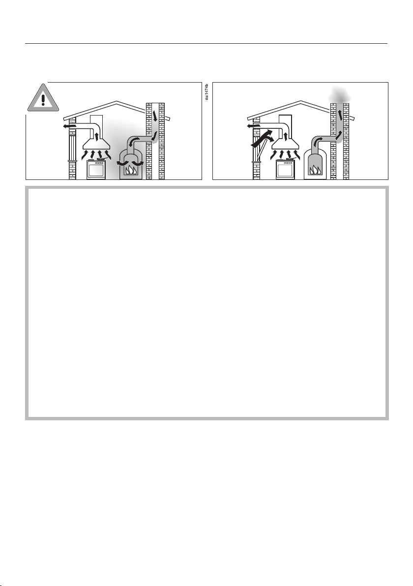
Using at the same time as another heating appliance that depends on the air from the room
Danger of toxic fumes!
Great care should be taken when using the external motor in the
same room or the same area of the house as another heating
appliance that depends on the air from the room.
Such heating appliances draw in air from the room and duct
exhaust gases out through a chimney or extraction ducting. They
include gas, oil, wood and coal-fired boilers and heaters,
continuous flow or other water heaters, gas cooktops and ovens.
The external motor draws in air from the kitchen and from
neighbouring rooms.
If there is insufficient air, an underpressure will occur. The heating
appliance may be starved of oxygen. This impairs combustion.
Harmful gases could be drawn from the chimney or extraction
ducting back into the room, with potentially fatal consequences.
Risk of death!
6
Page 7
Warning and Safety instructions
In order to ensure safe operation and to prevent gases given off by
the heating appliance from being drawn back into the room, when
the external motor and the heater are both operated
simultaneously, an underpressure in the room of 0.04mbar (4Pa)
is the maximum permissible.
Sufficient ventilation can be maintained by air inlets which cannot
be blocked, e.g. in windows, doors and outside wall vents. The
diameter of the inlet openings must enable sufficient ventilation. A
ventilation brick alone is not generally sufficient to ensure safe
ventilation.
The overall ventilation condition of the dwelling must be taken into
account. If in any doubt, the advice of a competent builder, or for
gas, a qualified gas fitter should be sought.
7
Page 8

Warning and Safety instructions
Correct installation
All ducting, pipework and fittings must be of non-flammable
material. These can be obtained from builders' merchants.
The appliance must not be connected to a chimney or vent flue
which is in current use for exhausting fumes from appliances burning
gas or other fuels. Neither should it be connected to ducting which
ventilates rooms with fireplaces.
8
Page 9
Caring for the environment
Disposal of the packing material
The transport and protective packaging
has been selected from materials which
are environmentally friendly for
disposal, and can normally be recycled.
Recycling the packaging reduces the
use of raw materials in the
manufacturing process and also
reduces the amount of waste in landfill
sites. Ensure that any plastic
wrappings, bags etc. are disposed of
safely and kept out of the reach of
babies and young children. Danger of
suffocation.
Disposing of your old appliance
Electrical and electronic appliances
often contain valuable materials. They
also contain specific materials,
compounds and components, which
were essential for their correct function
and safety. These could be hazardous
to human health and to the environment
if disposed of with your domestic waste
or if handled incorrectly. Please do not,
therefore, dispose of your old appliance
with your household waste.
Please dispose of it at your local
community waste collection / recycling
centre for electrical and electronic
appliances. You are also responsible for
deleting any personal data that may be
stored on the appliance prior to
disposal. Please ensure that your old
appliance poses no risk to children
while being stored prior to disposal.
9
Page 10

Installation
Before installation
Before installation, it is important
to read the information given on the
following pages as well as the
"Warning and Safety instructions" at
the beginning of this booklet.
Installation recommendations
– Make sure that the installation
location is easily accessible.
Installation work must be able to be
carried out without danger. This is
also important if the appliance needs
to be serviced.
10
Page 11

AWG 102
The AWG 102 external motor is
designed to be installed on an outside
wall.
The external motor must be installed
vertically on the outside wall. The
extraction outlet must face
downwards.
The external motor is connected to the
rangehood by means of a control cable
and is operated by the controls on the
rangehood.
Installation
Unscrew the two fixing screws on the
underside of the external motor and
take the motor unit off its fixing
bracket.
The ducting collar on the motor unit has
a diameter of 125 mm when the
appliance is supplied.
If exhaust ducting with a diameter of
150mm is required, the front ring
of the collar must be cut at the join
with a sharp knife.
Please refer to the operating and
installation instructions for the
rangehood before installing the
external motor and ducting.
11
Page 12

Installation
Make a 185 mm hole in the wall.
Push the telescopic wall pipe into the
hole so that it is sitting flush.
The telescopic wall pipe will make it
easier to feed the control cable and
the flexible ducting through later on.
Connect the three mountings through
the fixing holes in the bracket as
illustrated.
Position the motor unit fixing bracket
on the outside wall. The control cable
connection must be at the bottom.
Mark the position of the three holes
to be drilled.
Drill three 8 mm holes and insert
S8 wall anchors in the holes.
12
Position the bracket onto the outside
wall again and feed the control cable
with the six-pole connectors through
the telescopic wall pipe into the
house.
If equipotential bonding is required,
pull the earth cable through the hole
provided.
Equipotential bonding is required if
the control cable is to be extended
by more than the length of the
extension cable supplied (see
"Electrical connection").
Page 13

Feed the flexible ducting through the
telescopic wall pipe and secure it to
the collar on the motor unit fixing
bracket with a hose clip.
Secure the bracket to the external
wall with three screws.
Extend the flexible ducting from the
inside of the wall along the wall pipe
and seal the gap between the ducting
and the wall pipe with jointing
compound.
Installation
Connect the control cable plug
connectors.
Use the extension cable supplied to
lengthen the control cable if
necessary.
Refit the motor unit and secure it on
the underside of the external motor
with the two fixing screws.
13
Page 14

Installation
DDG 102
The DDG102 is designed for
installation on an angled tile, slate or
shingle roof. The slope of the roof must
be at least 22° to prevent the ingress of
the elements, such as rain or snow.
Please refer to the operating and
installation instructions for the
rangehood before installing the
external motor and ducting.
The ducting collar on the external motor
has a diameter of 125 mm when the
appliance is supplied.
If exhaust ducting with a diameter of
150mm is required, the front ring
of the collar must be cut at the join
with a sharp knife.
Consult a roof tiler or roof plumber for
advice regarding other types of roofing.
Installation on a flat roof is not
possible.
Installation must only be carried out
by a qualified and competent person.
The external motor is connected to the
rangehood by means of a control cable
and is operated by the controls on the
rangehood.
14
Page 15

Installation
Unscrew the two fixing screws and
remove the motor unit from the base
plate.
Fit the three distance bushes to the
base plate.
Secure the base plate to the
mounting frame with the screws and
nuts supplied.
Refit the motor unit.
15
Page 16

Installation
Remove the roofing around the
installation area.
Bend the flashing upwards.
Position the motor unit on the roof
with the air outlet directed down the
roof.
Secure the motor unit to the roof
substructure with the fixing plate .
Replace the roofing. Press down on
the flashing to ensure that it creates a
proper seal.
The flashing should be fitted under
the roofing at the top of the motor
unit and above the roofing at the
sides and bottom of the motor unit.
If equipotential bonding is required,
connect the earth lead to the earthed
connection point in the housing.
Equipotential bonding is required if
the control cable is to be extended
by more than the length of the
extension cable supplied (see
"Electrical connection").
Push the flexible ducting onto the
connection on the motor unit and
secure it with a hose clip.
Connect the control cable plug
connectors.
Use the extension cable supplied to
lengthen the control cable if
necessary.
When feeding the cable and the
exhaust ducting through the
substructure of the roof, be careful to
ensure that any gaps are sealed
properly afterwards.
16
Page 17
Installation
ABLG 202
1) Suction side
The ABLG 202 external motor is
designed for installation inside the
house. Possible locations:
– In the attic or ceiling space
– In an adjoining room, e.g. a pantry or
garage
– In the kitchen, if sufficient insulation
is used
It can be installed in a vertical or
horizontal position.
If installing vertically please refer to
the installation instructions on the
next page.
The external motor is connected to the
rangehood by means of a control cable
and is operated by the controls on the
rangehood.
Position the external motor in a
suitable location.
Pay particular attention to the
direction of the ducting.
Mark the positions for the four motor
base plate holes on the installation
surface.
Place the motor to one side.
Drill four 8mm holes in the
positions marked to a depth of
40mm for securing the external
motor.
Press S8 anchors into the drill holes
so that they are flush.
Connect the installation mountings
through the fixing holes in the motor
unit base plate.
Secure the motor with the screws
supplied.
Please refer to the operating and
installation instructions for the
rangehood before installing the
external motor and ducting.
17
Page 18

Installation
The ducting collar on the motor unit has
a diameter of 150mm as standard.
If a diameter of 125mm is required a
reducing collar must be used.
This is available to order from Miele.
Push the flexible ducting onto the
collar and secure it with a hose clip.
Ducting with a diameter of 150mm is
then connected to the exhaust side.
If the exhaust air is to be ducted into
the open air, a telescopic wall vent kit
can be used. This is available to order
from Miele.
If the motor is installed vertically with
the exhaust ducting venting over a
roof, a roof vent kit DDF 125/150 or
similar must be used to prevent
rainwater from penetrating the
exhaust opening.
Connect the control cable plug
connectors.
Use the extension cable supplied to
lengthen the control cable if
necessary.
If equipotential bonding is required,
connect the earth lead to the earthed
connection point in the housing.
Equipotential bonding is required if
the control cable is to be extended
by more than the length of the
extension cable supplied (see
"Electrical connection").
18
Page 19
Installation
DDF 125/150
Remove the roofing around the
installation area.
Bend the flashing* upwards.
Position the roof vent on the roof with
the air outlet directed down the roof.
Secure the roof vent to the roof
substructure with the fixing plate.
Replace the roofing. Press down on
the flashing to ensure that it creates a
proper seal.
The flashing should be fitted under
the roofing at the top of the roof vent
and above the roofing at the sides
and the bottom of the roof vent.
The roof vent collar has a diameter of
150mm as standard.
If a diameter of 125mm is required a
reducing collar must be used.
Push the flexible ducting onto the
collar and secure it with a hose clip.
It has an integrated non-return flap.
*Flashing
The DDF 125/150 roof vent is designed
for installing ducting through an angled
tile, slate or shingle roof. The slope of
the roof must be at least 22° to prevent
the ingress of the elements, such as
rain or snow.
Consult a roof tiler or roof plumber for
advice regarding other types of roofing.
Installation on a flat roof is not
possible.
Installation must only be carried out
by a qualified and competent person.
When feeding the exhaust ducting
through the substructure of the roof,
be careful to ensure that any gaps
are sealed up properly afterwards.
19
Page 20

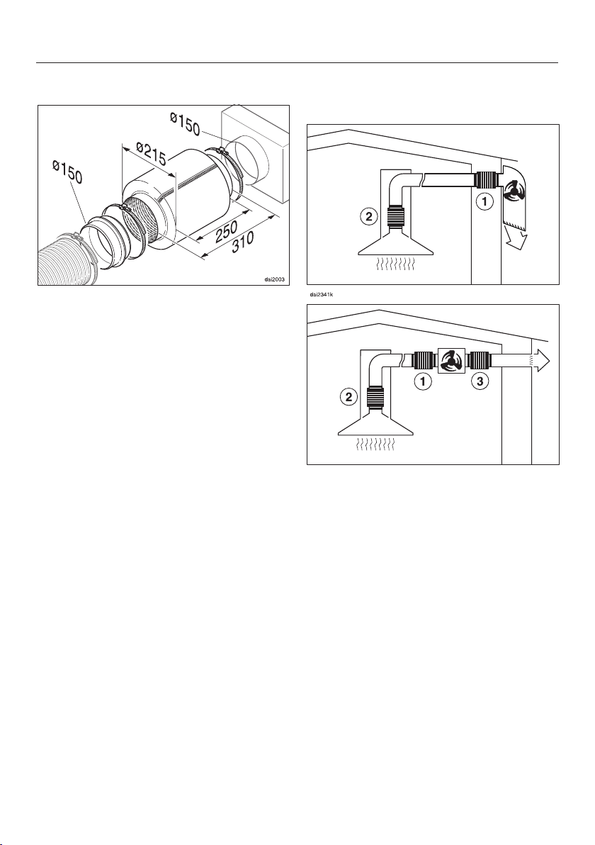
Connection for air extraction
Only use smooth pipes or flexible
hoses made from non-flammable
materials for the extraction ducting.
To achieve the greatest possible air
extraction with the lowest noise level,
please note the following:
– The cross-section of the exhaust
ducting must not be smaller than the
cross-section of the exhaust
connection (see "Appliance
dimensions").
– The exhaust ducting should be as
short and straight as possible.
– Only use wide radius bends.
– The exhaust ducting should not be
kinked or compressed.
– Ensure that all connections are
strong and airtight.
Remember that any constriction of
the airflow will reduce extraction
performance and increase operating
noise.
When ducting is horizontal it must be
laid to slope away at at least 1 cm per
metre. This is to ensure that
condensate cannot drain back into
the downdraft extractor.
If the exhaust ducting is to run
through rooms, ceiling space etc.
where there may be great variations
in temperature between the different
areas, the problem of condensation
will need to be addressed. The
exhaust ducting will need to be
suitably insulated.
If the exhaust air is to be ducted into
a vent flue, the ducting must be
directed in the flow direction of the
flue.
20
Page 21
Connection for air extraction
Silencer
To achieve even further reductions in
noise levels, a special silencer (optional
accessory) can be fitted in the ducting
system.
Air extraction with external motor
To minimise noise from the motor in the
kitchen, the silencer should be
positioned in front of the external motor
if possible, or if the ducting is long,
then in the ducting above the
rangehood itself . In the case of an
external motor that is placed inside the
house (ABLG 202), fitting a silencer
behind the external motor reduces
the noise of the motor outside the
house.
21
Page 22

After sales service and warranty
In the event of a fault which you cannot
remedy yourself, please contact Miele.
The contact details for Miele are given
at the back of these instructions.
When contacting Miele, please quote
the model and serial number of your
appliance.
These can be found on the data plate.
Position of the data plate
The data plate is located on the
housing.
Warranty: AU, NZ
The manufacturer's warranty for this
appliance is 2 years.
For further information, please refer to
your warranty booklet.
Warranty: Other countries
For information on the appliance
warranty specific to your country please
contact Miele. See end of this booklet
for contact details.
22
Page 23
The external motor is connected to the
rangehood by means of a special
control cable and is operated by the
touch controls on the rangehood.
The electrical system and connection of
this appliance must comply with
national and local safety regulations.
For extra safety, it is advisable to
protect the appliance with a suitable
residual current device (RCD) with a trip
current of 30mA.
The relevant connection data can be
found on the data plate (see "After sales
service and warranty"). Ensure that this
data matches the voltage and
frequency of your household mains
supply.
The external motor is supplied with a
5m extension cable. If the control
cable needs to be extended further
by means of an additional extension
cable or a hardwired connection
cable (at least 6x1.5mm²), the
installation must be carried out in
strict accordance with local and
national safety regulations.
Equipotential bonding is required in
this case.
The external motor is supplied with
an earthed connection point.
Electrical connection
This external motor has been
designed to be connected to a Miele
rangehood only and must not be
connected to a rangehood made by
another manufacturer.
23
Page 24
Technical data
AWG 102
Total rated load 200 W
Voltage, frequency AC 230 V, 50 Hz
Fuse rating 10 A
Control cable length 0.75 m
Connection cable length 5 m
Weight 14.1 kg
Operating temperature up to - 20°C
Fan power according to EN61591*
Level 1
Level 2
Level 3
Booster setting (intensive setting)
*For example in combination with a DA 429-6 EXT rangehood
320 m3/h
460 m3/h
580 m3/h
760 m3/h
24
Page 25
Technical data
ABLG 202
Total rated load 290 W
Voltage, frequency AC 230 V, 50 Hz
Fuse rating 10 A
Connection cable length 5 m
Weight 8 kg
Operating temperature up to - 20°C
Fan power according to EN61591*
Level 1
Level 2
Level 3
Booster setting (intensive setting)
*For example in combination with a DA 429-6 EXT rangehood
300 m3/h
460 m3/h
600 m3/h
820 m3/h
25
Page 26

Technical data
DDG 102
Total rated load 200 W
Voltage, frequency AC 230 V, 50 Hz
Fuse rating 10 A
Control cable length 0.75 m
Connection cable length 5 m
Weight 15.2 kg
Operating temperature up to - 20°C
Fan power according to EN61591*
Level 1
Level 2
Level 3
Booster setting (intensive setting)
*For example in combination with a DA 429-6 EXT rangehood
320 m3/h
460 m3/h
580 m3/h
760 m3/h
26
Page 27

www.miele.com.au
Miele Experience Centre and
Head Office Melbourne:
1 Gilbert Park Drive
Knoxfield, VIC 3180
Miele Experience Centre South Melbourne:
206-210 Coventry Street
South Melbourne, VIC 3205
Miele Experience Centre and Office Sydney:
3 Skyline Place
Frenchs Forest, NSW 2086
Miele Experience Centre and Office Brisbane:
39 Harvey Street North
Eagle Farm, QLD 4009
Miele Experience Centre and Office Perth:
83-85 Sir Donald Bradman Drive
Hilton, SA 5033
205-207 Stirling Highway
Claremont, WA 6010
Miele Experience Centre and Office Adelaide:
Miele Australia Pty. Ltd.
Miele New Zealand Limited
Level 2, 10 College Hill
Freemans Bay, Auckland 1011
Miele Experience Centre
Auckland:
8 College Hill
Freemans Bay, Auckland 1011
Telephone:
0800 464 353 (0800 4 MIELE)
www.miele.co.nz
Miele Global Headquarters
Germany
Miele & Cie. KG
Carl-Miele-Straße 29
33332 Gütersloh
Federal Republic of Germany
Head Office:
IRD 98 463 631
ACN 005 635 398
ABN 96 005 635 398
Miele Experience Centre Gold Coast:
131 Ferry Road
Southport, QLD 4215
Page 28

AWG 102
DDG 102
ABLG 202
DDF 125/150
M.-Nr. 10 695 670 / 01en - AU, NZ
 Loading...