


Contents i
R410A ON/OFF SERIES
Service Manual 2013
LEUS-B-1306


Content
Contents i
Part 1 General Information ................................................................... 1
Part 2 Indoor Units ................................................................................ 6
Part 3 Outdoor Units ........................................................................... 63
Part 4 Installation ................................................................................ 78
Part 5 Electrical Control System .....................................................104
※The specifications, designs, and information in this book are subject to change without notice for
product improvement.


General Information
General Information 1
Part 1
General Information
1. Model Lists ................................................................................................................ ....... 2
2. External Appearance ....................................................................................................... 3
2.1 Indoor Units ............................................................................................................... 3
2.2 Outdoor Units ............................................................................................................ 3
3. Nomenclature ................................................................................................................... 4
4. Features ............................................................................................................................ 5
Model Lists
2 General Information
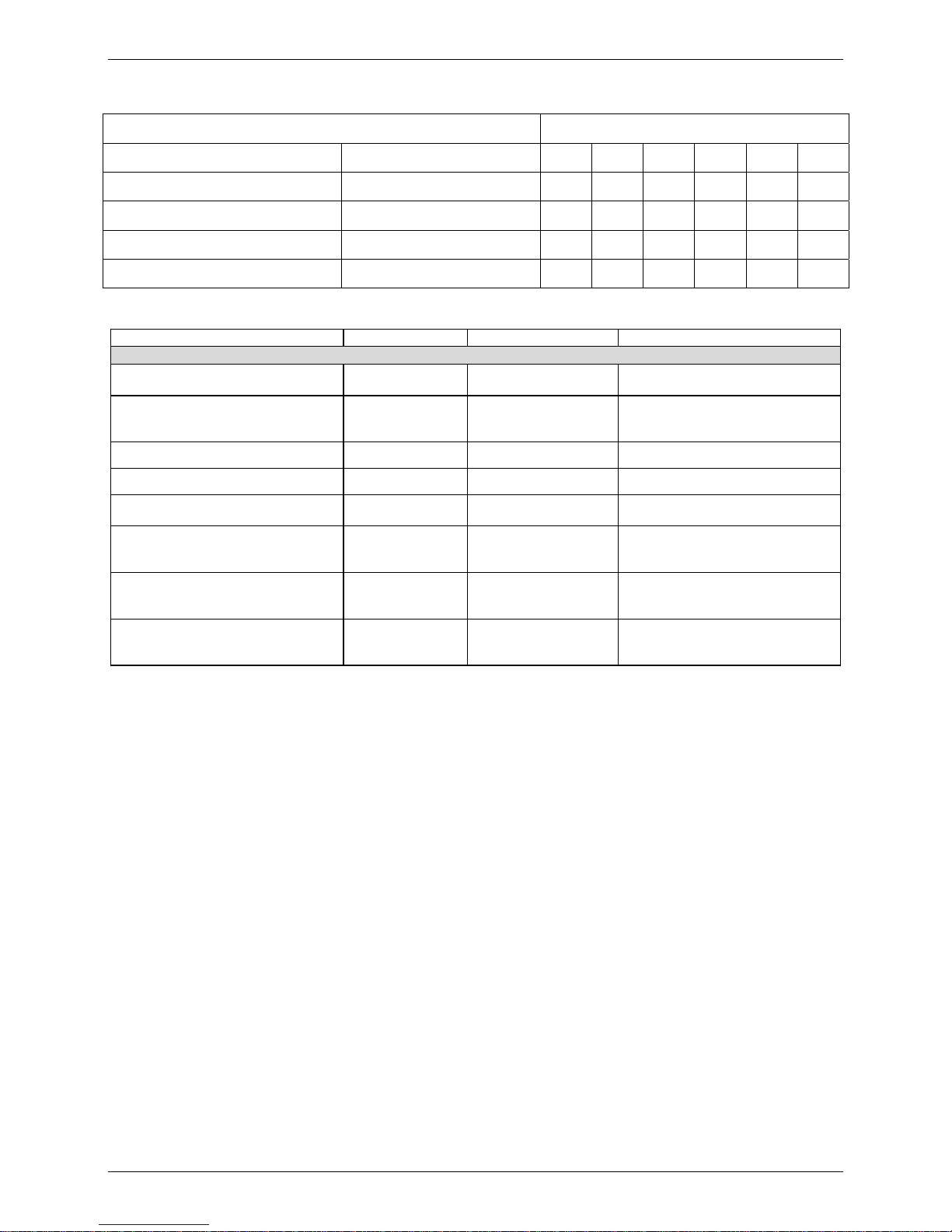
1. Model Lists
1.1 Indoor Units
R410A Capacity multiplied by 1000Btu/h
Type Function 18 24 30 36 48 60
A5 High static pressure duct Cooling and heating
● ● ● ● ● ●
Ceiling & Floor Cooling and heating
● ● ●
Super-slim 4-way cassette Cooling and heating
● ● ● ● ●
High static pressure duct Cooling and heating
●
1.2 Outdoor Units
Universal Outdoor unit Model Compressor type Compressor Brand Matched indoor units
Heat Pump
MOU-18HN1-Q ROTARY CMCC
MHF-18HWN1-Q
MCD-18HRN1-Q
MOU-24HN1-Q ROTARY CMCC
MHF-24HWN1-Q
MCD-24HRN1-Q
MHG-24HWN1-Q
MOU-30HN1-Q ROTARY CMCC MHF-30HWN1-Q
MOU-30HN1-R ROTARY CMCC MHF-30HWN1-R
MOU-36HN1-Q SCROLL SANYO
MHF-36HWN1-Q
MUE-36HRN1-Q
MOU-36HN1-R SCROLL SANYO
MHF-36HWN1-R
MUE-36HRN1-R
MCD-36HRN1-R
MOU-48HN1-R SCROLL SANYO
MHF-48HWN1-R
MUE-48HRN1-R
MCD-48HRN1-R
MOUA-60HN1-R SCROLL SANYO
MHF-60HWN1-R
MUE-60HRN1-R
MCD-60HRN1-R
External Appearance
General Information 3
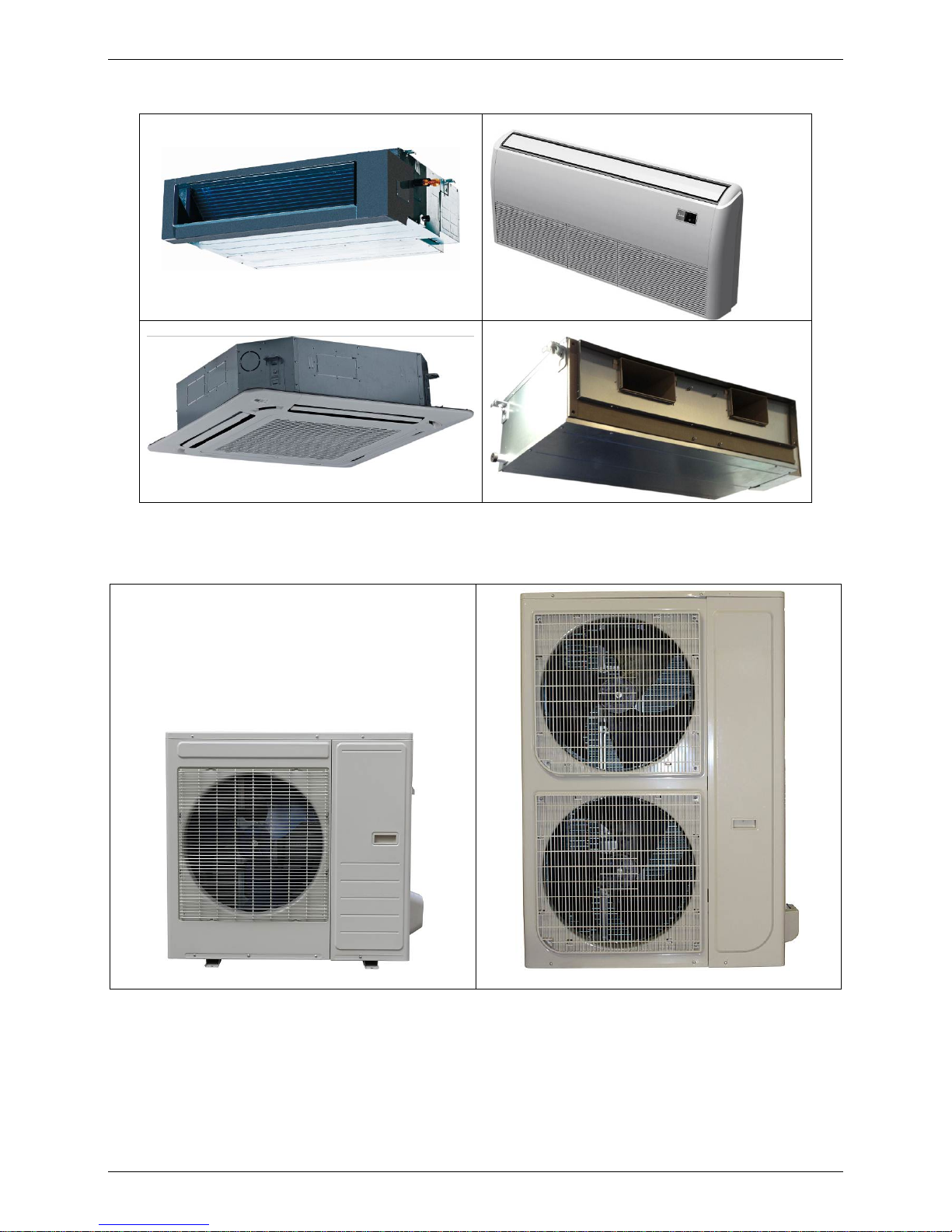
2. External Appearance
2.1 Indoor Units
A5 High static pressure duct
Ceiling & floor type
Super-slim 4-way Cassette High static pressure duct
2.2 Outdoor Units
Single fan outdoor unit
Double fan outdoor unit
Nomenclature
4 General Information
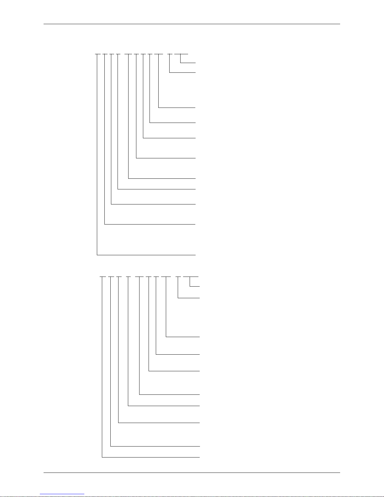
3. Nomenclature
3.1 Indoor Unit
M U B T- 36 H R D N1- Q RC4
Energy Efficiency Code
Power Supply
Q 220~240V,1N, 50Hz
R 380~420V, 3N, 50Hz
N 220~230V, 1N, 60Hz
D 220V~, 3N, 60Hz
C 380~420V,3N,60Hz
Refrigerant
N1 R410A -- R22
D DC Inverter -- On-Off
F Full DC
Control Mode
W Wired Control E Electric Control
M Mechanical Control R Remote Control
Function Code
C Cooling Only H Cooling & Heating
A Cooling & Heating+PTC
Capacity (×1000Btu/h)
T Tropical Condition
-- T1 Condition
Designed Time
A Time A Designed B Time B Designed
C Time C Designed D Time D Designed
Product Category
C Cassette Type V AHU Type
T Duct Type F Console Type
U Ceiling & Floor Type
H High Static Pressure Duct Type
Midea
3.2 Outdoor Unit
M O U T- 36 H D N1- R RC4
Energy Efficiency Code
Power Supply
Q 220~240V,1N, 50HZ
R 380~420V, 3N, 50Hz
N 220~230V, 1N, 60Hz
D 220V~, 3N, 60Hz
C 380~420v,3N,60HZ
Refrigerant
N1 R410A -- R22
D DC Inverter -- On-Off
F Full DC
Function Code
C Cooling Only H Cooling & Heating
A Cooling & Heating+PTC
Capacity (×1000Btu/h)
T Tropical Condition
-- T1 Condition
U Side Discharge Outdoor Unit
V Top Discharge Outdoor Unit
S Centrifugal Fan Outdoor Unit
O Outdoor unit
Midea
Features
General Information 5
4. Features
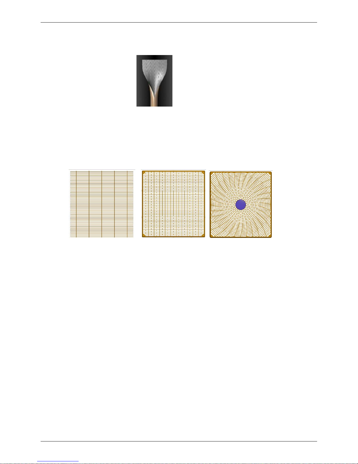
4.1 High quality coils:
The coil is constructed of advanced inner grooved copper tube and aluminum fins.
4.2 Anti-rust, 500 hours salt spray test.
4.3 Low operation sound level: Well-known stable and quiet running fan motor.
4.4 Well-known compressor.
4.5 Compact design: Smaller dimension and larger stuffing capacity.
4.6 Universal outdoor unit design.
4.7 Optional air outlet grille: plastic type and wire type.
Wire type Plastic type Plastic type
4.8 Optional low temperature cooling module.
4.9 R410A environment friendly refrigerant.

Indoor Units
6 Indoor Units
Part 2
Indoor Units
A5 High Static Pressure Duct Type ..................................... 7
Ceiling & Floor Type ........................................................... 25
Super-slim Cassette Type .................................................. 35
High Static Pressure Duct Type ......................................... 52

A5 High Static Pressure Duct Type
Duct Type 7
A5 High Static Pressure Duct Type
1. Features ...................................................................................................... 8
2. Dimensions ............................................................................................... 11
3. Service Space ........................................................................................... 12
4. Wiring Diagrams ....................................................................................... 13
5. Static Pressure ......................................................................................... 18
6. Electric Characteristics ........................................................................... 19
7. Sound Levels ............................................................................................ 20
8. Accessories .............................................................................................. 21
9. The Specification of Power ..................................................................... 22
10. Field Wiring ............................................................................................. 23
Features
8 Duct Type
1. Features
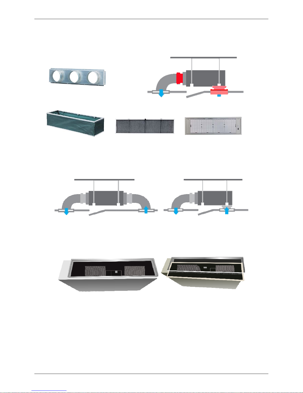
1.1 Installation accessories: (Optional)
Front Board, Canvas Air Passage, Filter, Panel, for easy installation
1.2 Easy Installation: Two air inlet styles (Bottom side or Rear side)
Air inlet from rear is standard for all capacity; air inlet from bottom is optional.
The size of air inlet frame from rear and bottom is same, it’s very easy to move the cover from bottom to
rear side, or from rear to the bottom, in order to matching the installation condition.
1.3 Easy maintenance
Clean the filter (Optional, standard product without filter)
It is easy to draw out the filter from the indoor unit for cleaning, even the filter is installed in rear side or
bottom side.
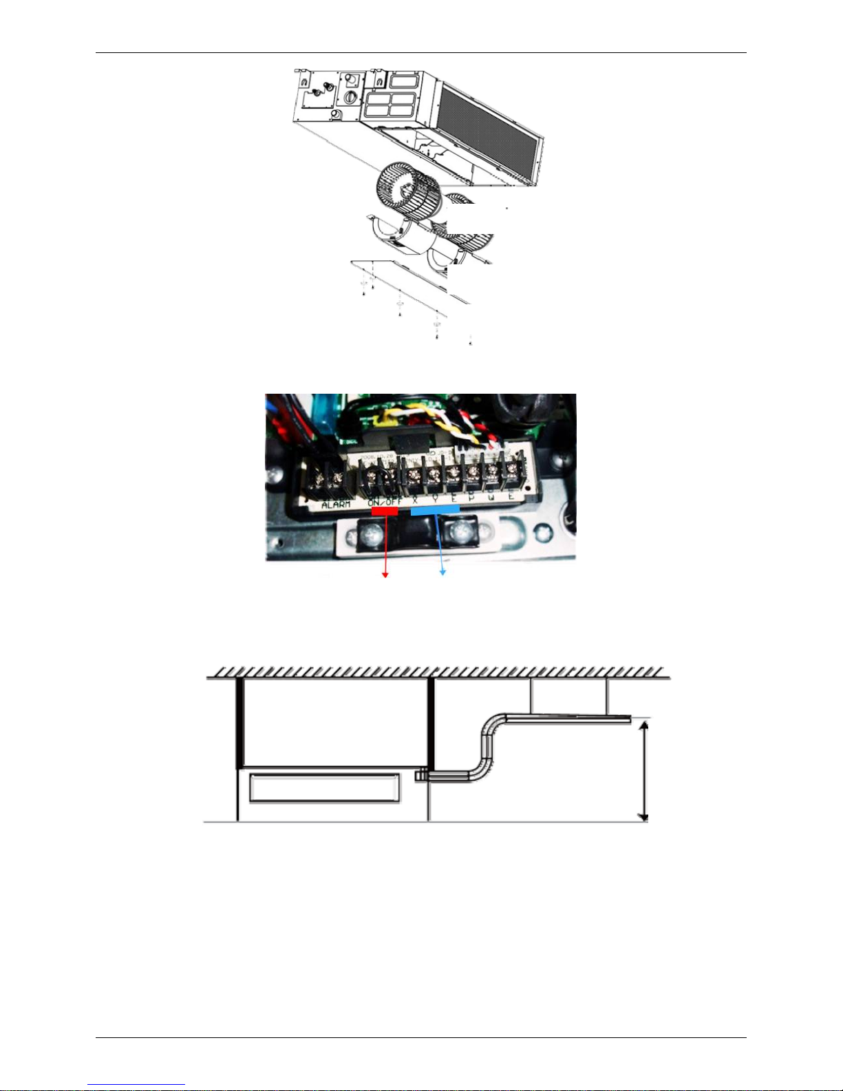
Replace the motor or centrifugal fan
Remove the ventilated panel firstly. Remove a half of blower housing and take out the motor with
centrifugal fan. Directly remove two bolts, and then replace the motor or centrifugal fan easily.
Front Board
Canvas Air Passage Filter Panel
Air intake from rear (Standard)
Air intake from bottom (Optional)
Features
Duct Type 9
1.4 Reserved remote on-off and central control ports
Reserved remote on-off ports and central control ports, can connect the cable of an on-off controller or a
central controller to realize remote on-off control function or group control function.
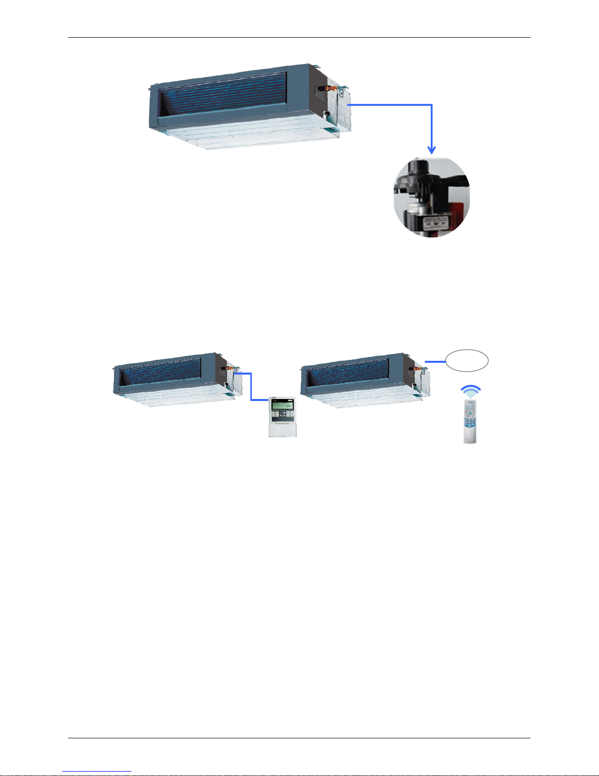
1.5 Built-in drain pump (Optional):
Built-in drain pump can lift the water to 750mm upmost. It’s convenient to install drainage piping under
most space condition.
Motor
Blower Housing
Ventilated Panel
Remote on-off ports
Central control ports
750mm upmost
Features
10 Duct Type
1.6 Built-in display board
The standard indoor unit can be controlled by wired controller.
There is a display board with a receiver in the E-box. Move out the display, and fix it in other place, even
in the distance of 10m. The unit will realized remoter control.
The wired controller and the display board can display the error code or production code when the chips
detect some failure.
Display
Wired Controller (Standard)
Remote Controller (Optional)

Dimensions
Duct Type 11
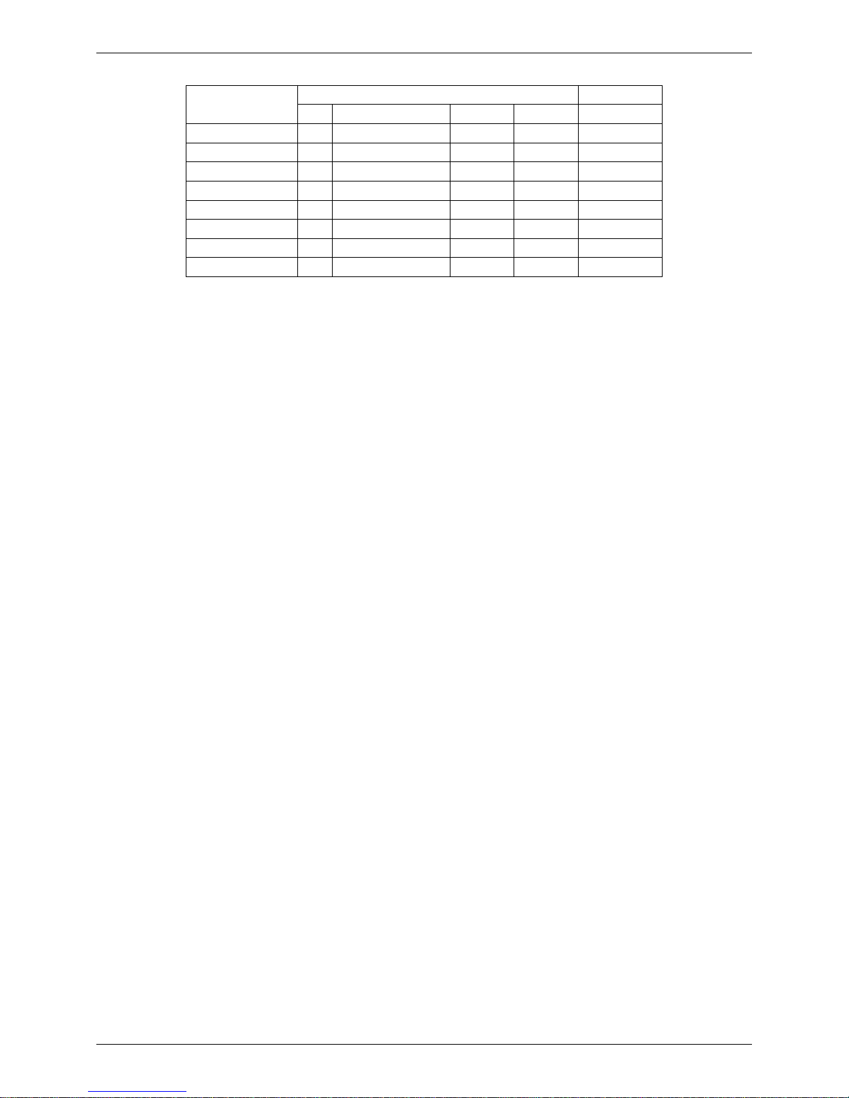
2. Dimensions
H
G
E
F
A
B
D
C
L
M
Capacity
(KBtu)
Outline
dimension(mm)
Air outlet
opening size
Air return
opening size
Size of outline dimension
mounted plug
A B C D E F G H I J K L M
18 920 210 635 570 65 713 35 119 815 200 80 960 350
24 920 270 635 570 65 713 35 179 815 260 20 960 350
30/36 1140 270 775 710 65 933 35 179 1035 260 20 1180 490
48/60 1200 300 865 800 80 968 40 204 1094 288 45 1240 500
Service Space
12 Duct Type
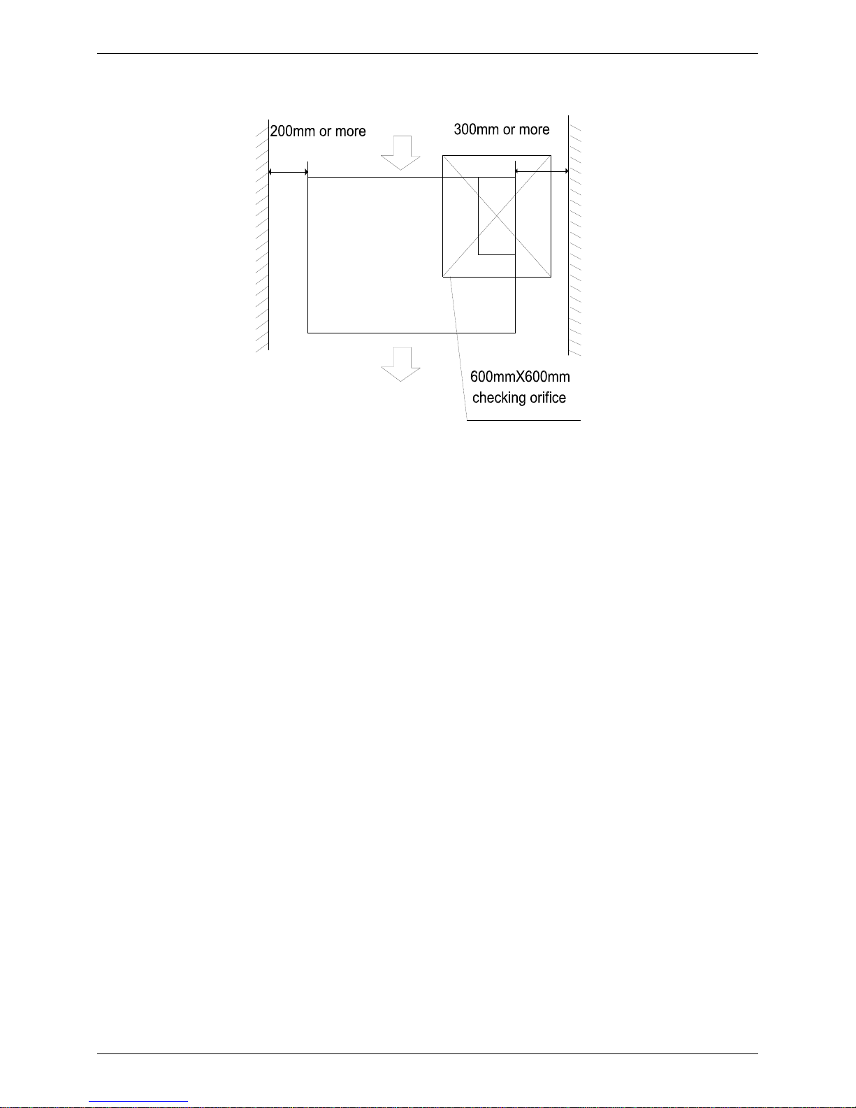
3. Service Space
Ensure enough space required for installation and maintenance.
Wiring Diagrams
Duct Type 13
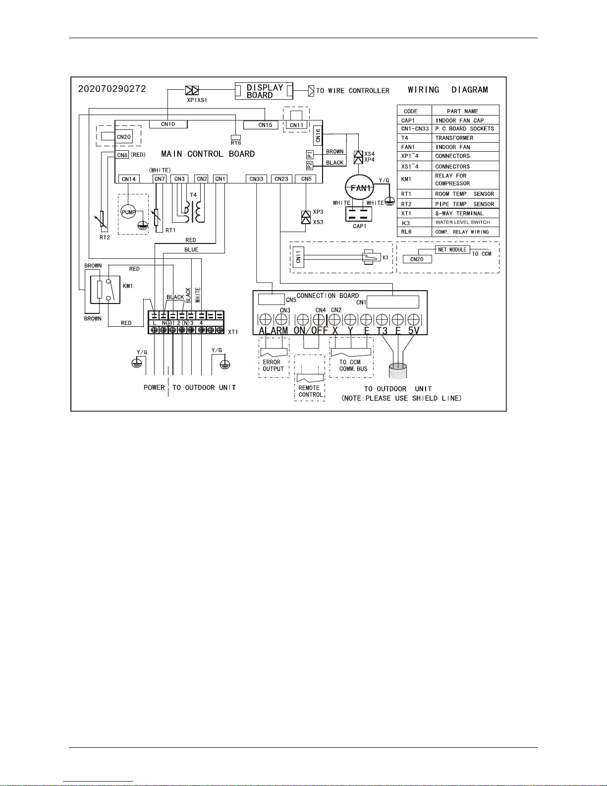
4. Wiring Diagrams
MHF-18HWN1-Q
Wiring Diagrams
14 Duct Type
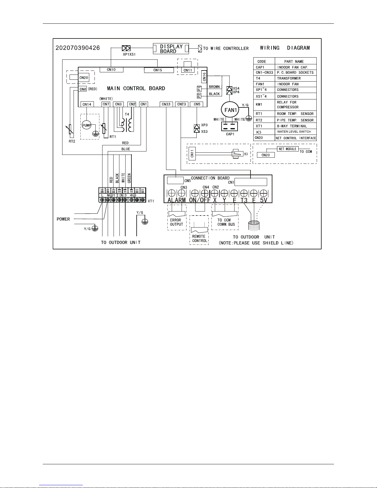
MHF-24HWN1-Q
Wiring Diagrams
Duct Type 15
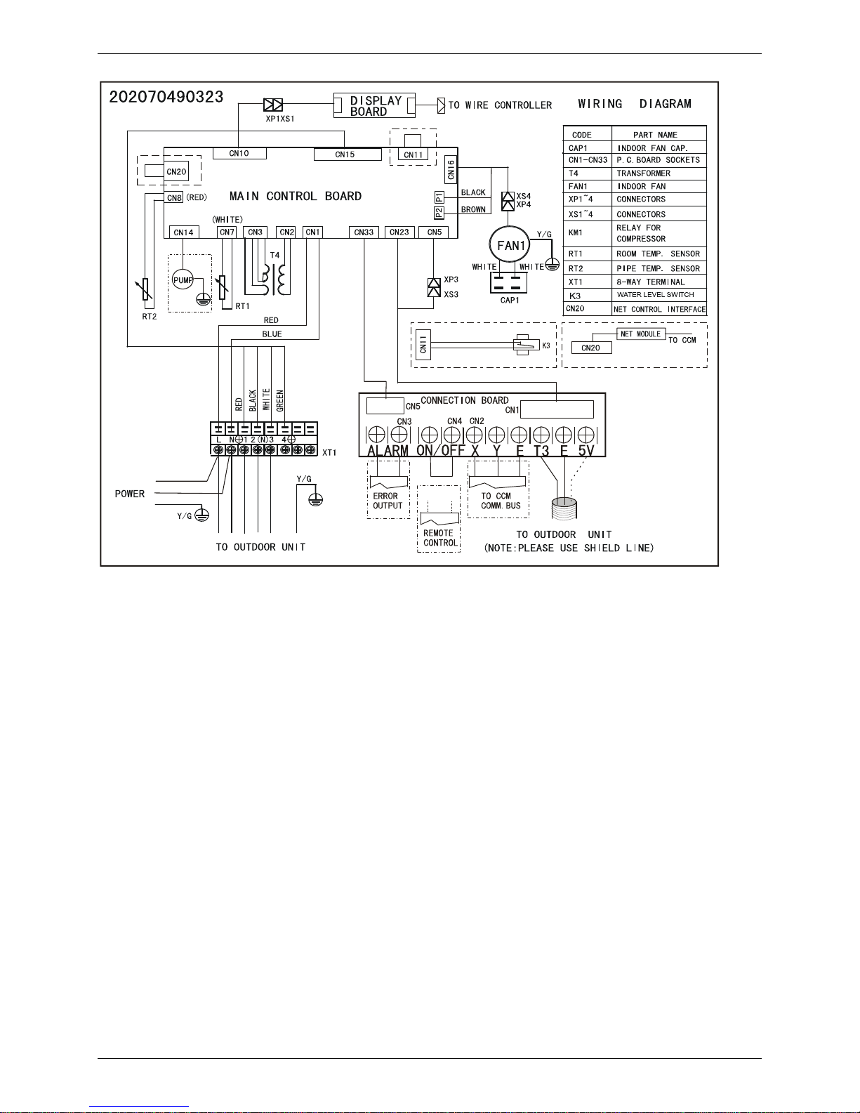
MHF-30HWN1-Q、MHF-36HWN1-Q

Wiring Diagrams
16 Duct Type
MHF-30HWN1-R、MHF-36HWN1-R、MHF-48HWN1-R、MHF-60HWN1-R

Wiring Diagrams
Duct Type 17
Static Pressure
18 Duct Type
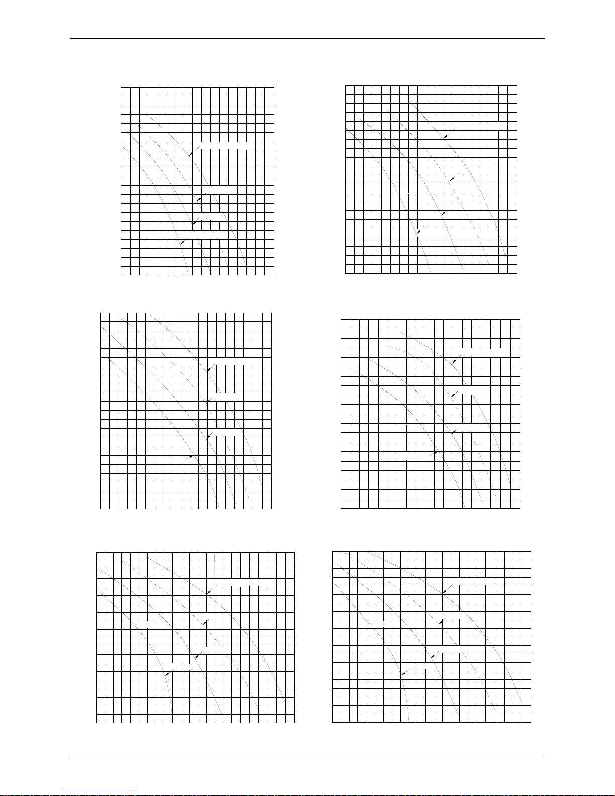
5. Static Pressure
18,000 Btu/h 24,000 Btu/h
Mid speed
High speed
External static pressure (Pa)
14001300
1200
1100
1000
Pa
90
80
70
60
50
40
30
20
10
Low speed
700
Super high speed
800
900
1500
3
Air volume(m /h)
Mid speed
High speed
External static pressure (Pa)
14001300
1200
1100
1000
Pa
90
80
70
60
50
40
30
20
10
Low speed
700
Super high speed
800
900
1500
1600
3
Air volume(m /h)
30,000 Btu/h 36,000 Btu/h
Mid speed
High speed
External static pressure (Pa)
2000
1800
1600
1400
1200
Pa
90
80
70
60
50
40
30
20
10
Low speed
600
Super high speed
800
1000
2200
2400
3
Air volume(m /h)
100
Mid speed
High speed
External static pressure (Pa)
2000
1800
1600
1400
1200
Pa
180
160
140
120
100
80
60
40
20
Low speed
600
Super high speed
800
1000
2200
2400
3
Air volume(m /h)
48,000 Btu/h 60,000 Btu/h
Mid speed
High speed
External static pressure (Pa)
3200
3000
2800
2600
2400
Pa
180
160
140
120
100
80
60
40
20
Low speed
800
Super high speed
1000
2200
3400
3600
3
Air volume(m /h)
2000
1600
Mid speed
High speed
External static pressure (Pa)
3200
3000
28002600
2400
Pa
180
160
140
120
100
80
60
40
20
Low speed
800
Super high speed
1000
2200
3400
3600
3
Air volume(m /h)
2000
1600
Electric Characteristics
Duct Type 19
6. Electric Characteristics
Model
Indoor Units Power Supply
Hz Voltage Min. Max. MFA
MHF-18HWN1-Q 50 220-240V 198V 254V 16
MHF-24HWN1-Q 50 220-240V 198V 254V 25
MHF-30HWN1-Q 50 220-240V 198V 254V 30
MHF-30HWN1-R 50 380-420V 342V 440V 20
MHF-36HWN1-Q 50 220-240V 198V 254V 30
MHF-36HWN1-R 50 380-420V 342V 440V 20
MHF-48HWN1-R 50 380-420V 342V 440V 20
MHF-60HWN1-R 50 380-420V 342V 440V 20
Notes:
MFA: Max. Fuse Amps. (A)
Sound Levels
20 Duct Type
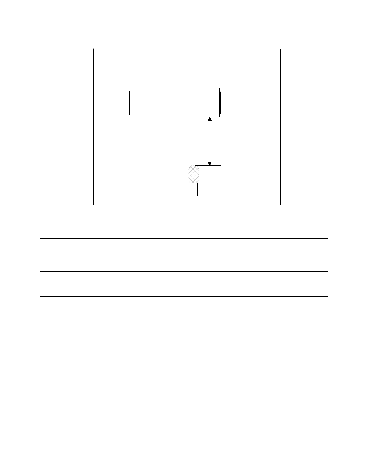
7. Sound Levels
Suction
Discharge
Microphone
1.4m
Concealed Duct Type
DuctDuct
Model
Noise level dB(A)
H M L
MHF-18HWN1-Q 42 38 36
MHF-24HWN1-Q 46 40 38
MHF-30HWN1-Q 50 48 45
MHF-30HWN1-R 50 48 45
MHF-36HWN1-Q 52 48 45
MHF-36HWN1-R 49 47 44
MHF-48HWN1-R 51 49 46
MHF-60HWN1-R 50 48 44
Accessories
Duct Type 21
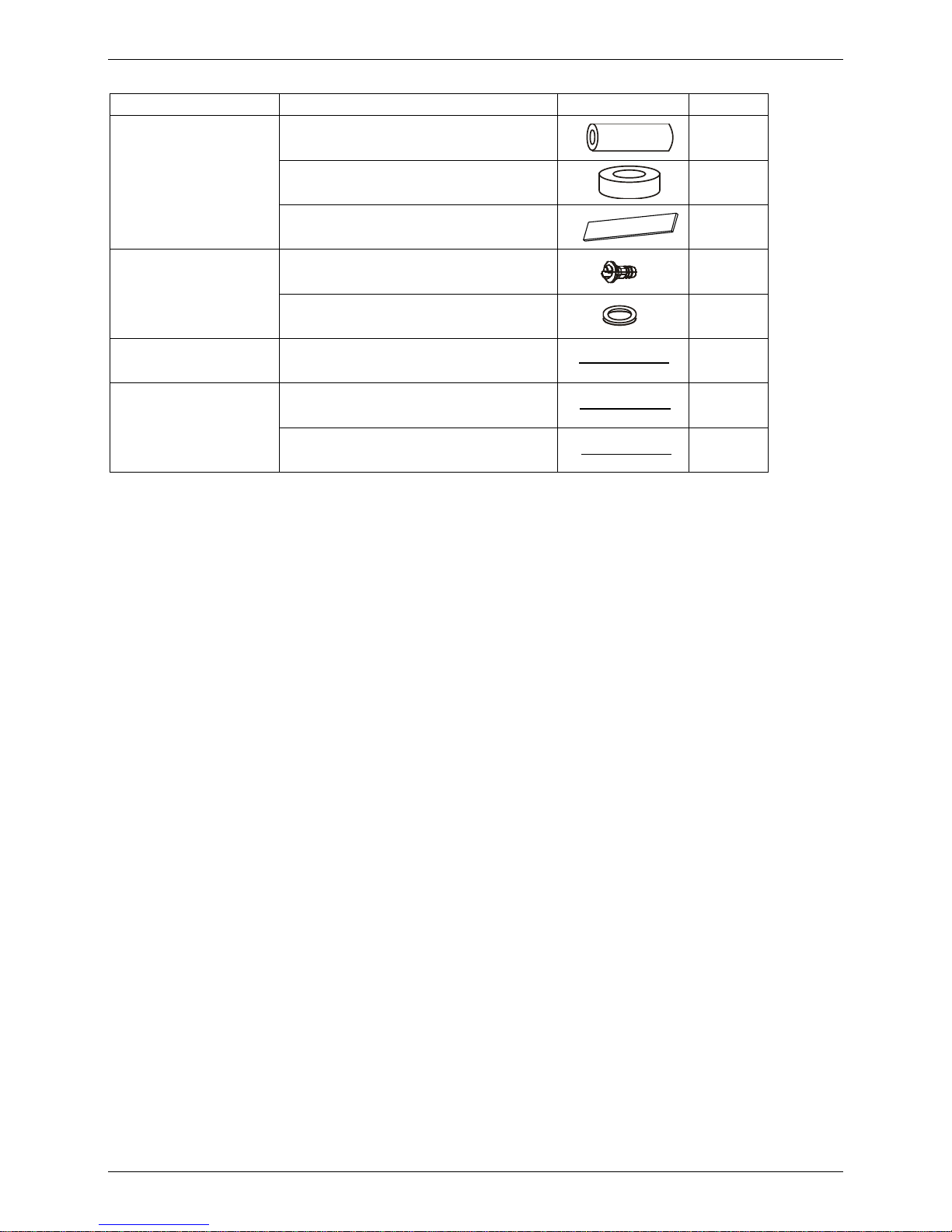
8. Accessories
Name Shape Quantity
Tubing & Fittings
Soundproof/insulation sheath
2
Binding tape
1
Seal sponge
1
Drainpipe Fittings
Drain joint
1
Seal ring
1
Wire controller Wire controller
1
others
Owner's manual
1
Installation manual
1
The Specification of Power
22 Duct Type
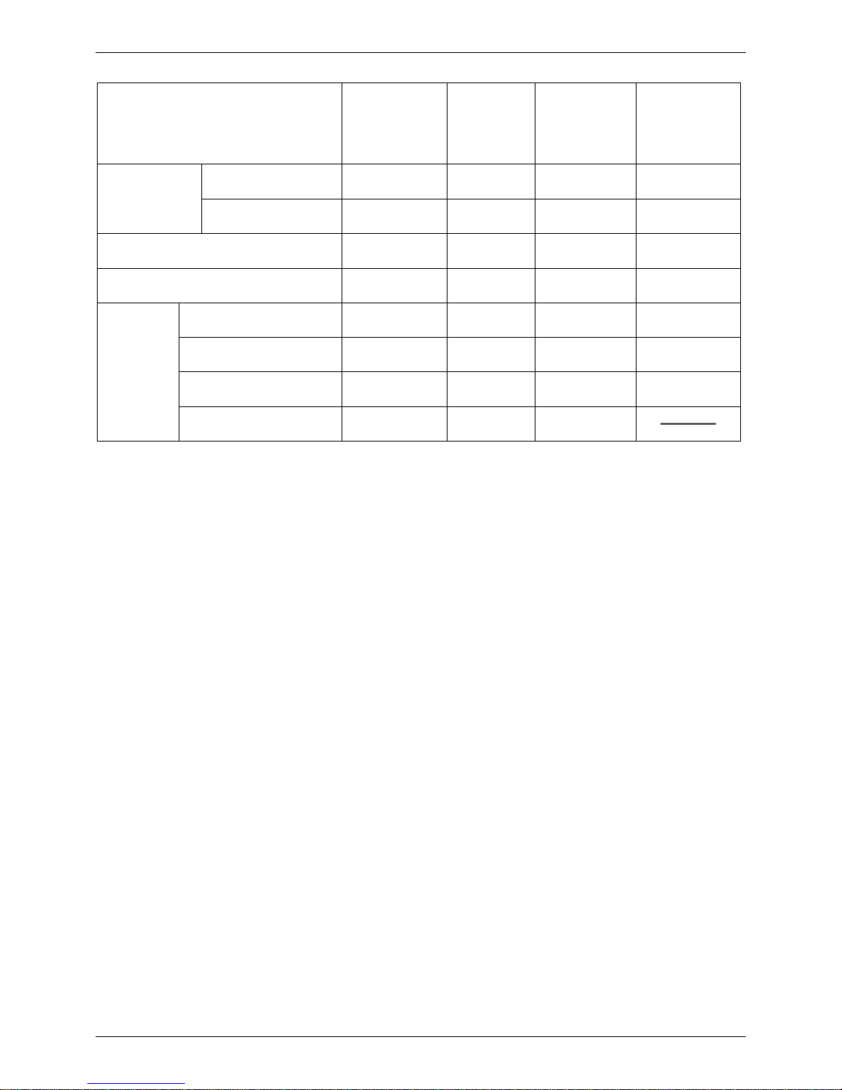
9. The Specification of Power
Model
18000 Btu/h 24000 Btu/h
30000-36000
Btu/h
30000-60000
Btu/h
Power
Phase 1-Phase 1-Phase 1-Phase 3-Phase
Frequency and Volt
220-240V,50Hz 220-240V,50Hz 220-240V,50Hz 380-415V, 50Hz
Circuit Breaker/Fuse(A) 20/16 40/25 50/30 25/20
Indoor unit power wiring(mm²) 3×2.5 3×2.5 3×4.0 5×2.5
Indoor/outdoor
connecting
wiring(mm²
)
Ground wiring 2.5 2.5 4.0 2.5
Outdoor unit power wiring 3×2.5 3×2.5 3×4.0 5×2.5
Strong electric signal 2×1.0 3×1.0 3×1.0 3×1.0
Weak electric signal 2×0.75/2×0.5 2×0.2 2×0.2
Field Wiring
Duct Type 23
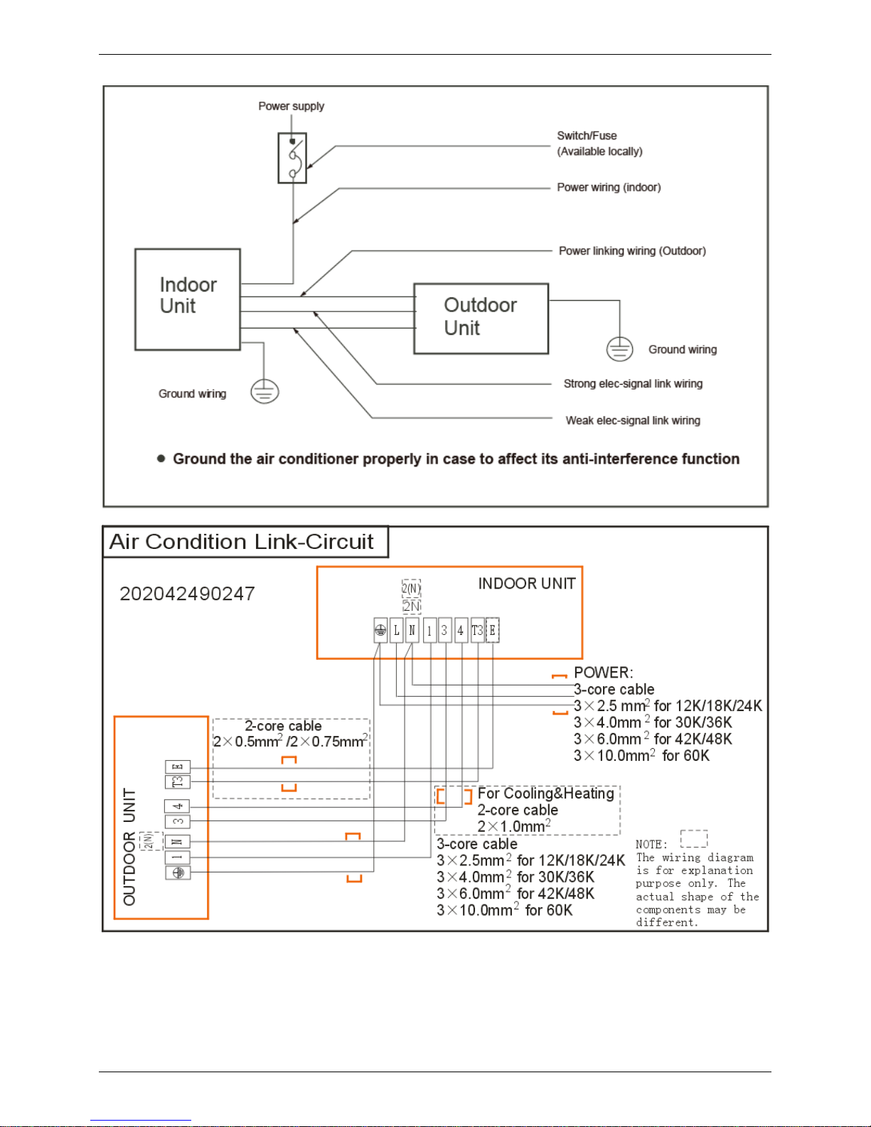
10. Field Wiring
MHF-18HWN1-Q
Field Wiring
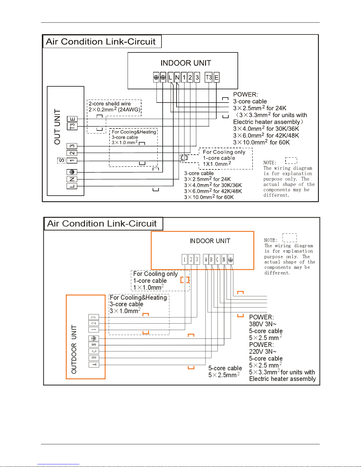
24 Duct Type
MHF-24HWN1-Q、MHF-30HWN1-Q、MHF-36HWN1-Q
MHF-30HWN1-R、MHF-36HWN1-R、MHF-48HWN1-R、MHF-60HWN1-R

Ceiling & Floor Type
Ceiling & Floor Type 25
Ceiling & Floor Type
1. Features ........................................................................... 26
2. Dimensions ...................................................................... 27
3. Service Space .................................................................. 28
4. Wiring Diagrams ............................................................. 29
5. Electric Characteristics .................................................. 31
6. Sound Levels ................................................................... 31
7. Accessories ..................................................................... 32
8. The Specification of Power ............................................ 32
9. Field Wiring ..................................................................... 33
Features
26 Ceiling & Floor Type
1. Features
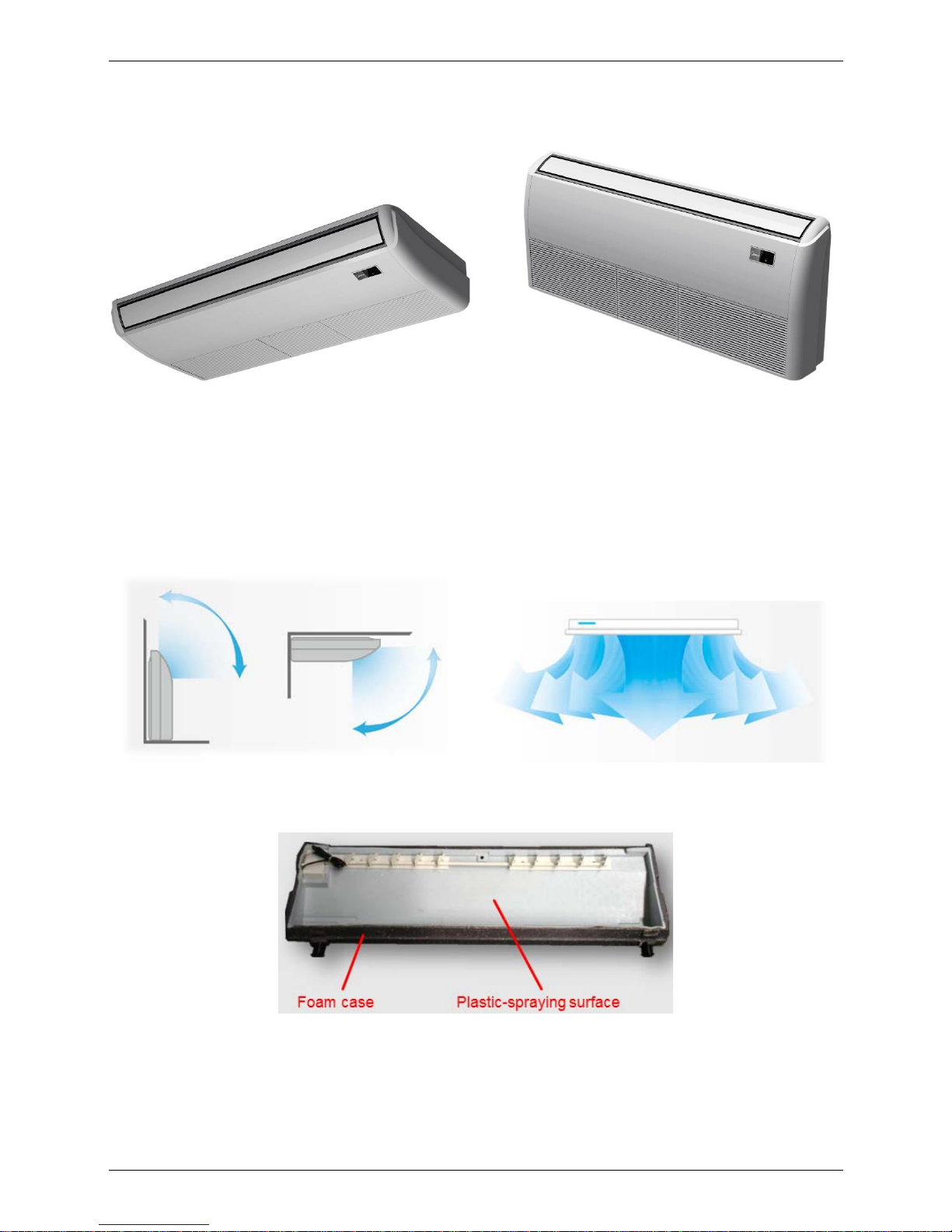
1.1. New design, more modern and elegant appearance.
1.2. Convenient installation
--The ceiling type can be easily installed into a corner of the ceiling even if the ceiling is very narrow
--It is especially useful when installation of an air conditioner in the center of the ceiling is impossible
due to a structure such as one lighting.
1.3. Two direction auto swing (vertical & horizontal) and wide angle air flow,
--Air flow directional control minimizes the air resistance and produces wilder air flow to vertical
direction.
--The range of horizontal air discharge is widened which secures wider air flow distribution to provide
more comfortable air circulation no matter where the unit is set up
1.4. Three level fan speed, more humanism design, meets different air-supply requirement.
1.5. New foam drain pan with plastic-spraying inner surface
1.6. Easy operation.
1.7. Remote control and optional wired control method.

Dimensions
Ceiling & Floor Type 27
2. Dimensions
Capacity (Btu/h)
A B C D E
36K 1285 675 235 1200 220
48K, 60K 1650 675 235 1565 220

Service Space
28 Ceiling & Floor Type
3. Service Space

Wiring Diagrams
Ceiling & Floor Type 29
4. Wiring Diagrams
MUE-36HRN1-Q

Wiring Diagrams
30 Ceiling & Floor Type
MUE-36HRN1-R、MUE-48HRN1-R、MUE-60HRN1-R

Electric Characteristics
Ceiling & Floor Type 31
5. Electric Characteristics
Model
Indoor Units Power Supply
Hz Voltage Min. Max. MFA
MUE-36HRN1-Q 50 220-240V 198V 242V 30
MUE-36HRN1-R 50 380-420V 342V 440V 20
MUE-48HRN1-R 50 380-420V 342V 440V 20
MUE-60HRN1-R 50 380-420V 342V 440V 20
Remark:
MFA: Max. Fuse Amps. (A)
6. Sound Levels
Microphone
1m
1m
Air outlet side
1.5m
1m
Microphone
Ceiling Floor
Model
Noise level dB(A)
H M L
MUE-36HRN1-Q 53 48 44
MUE-36HRN1-R 53 48 44
MUE-48HRN1-R 53 48 44
MUE-60HRN1-R 54 49 46

Accessories
32 Ceiling & Floor Type
7. Accessories
Remote controller & Its
holder
1. Remote controller
1
2. Remote controller holder 1
3. Mounting screw (ST2.9×10-C-H) 2
4. Alkaline dry batteries (AM4) 2
Others
5. Owner's manual
1
6. Installation manual
1
7. Remote controller manual
1
8. The Specification of Power
Model
36000 Btu/h 30000-60000 Btu/h
Power
Phase 1-Phase 3-Phase
Frequency and Volt
220-240V,50Hz 380-415V, 50Hz
Circuit Breaker/Fuse(A) 50/30 25/20
Indoor unit power wiring(mm²) 3×4.0 5×2.5
Indoor/out-door connecting wiring(mm²)
Ground wiring 4.0 2.5
Outdoor unit power wiring 3×4.0 5×2.5
Strong electric signal 3×1.0 3×1.0
Weak electric signal 2×0.2

Field Wiring
Ceiling & Floor Type 33
9. Field Wiring
MUE-36HRN1-Q

Field Wiring
34 Ceiling & Floor Type
MUE-36HRN1-R、MUE-48HRN1-R、MUE-60HRN1-R

Super-slim Cassette Type
Super-slim Cassette Type 35
Super-slim Cassette Type
1. Features ...................................................................... 36
2. Dimensions ................................................................. 40
3. Service Space ............................................................. 41
4. Wiring Diagrams ......................................................... 42
5. Electric Characteristics ............................................. 46
6. Sound Levels .............................................................. 47
7. Accessories ................................................................ 48
8. The Specification of Power ....................................... 49
9. Field Wiring ................................................................. 50

Features
36 Super-slim Cassette Type
1. Features
1.1 Overview
Compact design, super slim body size, less space requiring in installation
Each louver can be separately controlled, more comfort air blowing is possible.
Auto-lifting panel design, more convenient to clean and maintain the filter. (optional)
Old Cassette New slim cassette Volume change
Dimension
18K-24K: 840*230*840 18K-24K: 840*205*840
11%↓
30K: 840*300*840 30K: 840*205*840
32%↓
36K-48K: 840*300*840 36K-48K: 840*245*840
18%↓
1.2
Fresh air intake function
Fresh air fulfills air quality more healthy and comfortable.
Ventilation motor is optional to increase the effect of fresh air.

Features
Super-slim Cassette Type 37
1.3 Optional ionizer generator
Ionizer generator is optional to get refreshing air to your room.
Ionizer can be switched on or off by remote controller.
When pressing the Clean Air button on the remote controller, Ionizer will work and the indicator light on
display board will shine.
New air-intake
IIoonniizzeerr ggeenneerraattoorr
ccoonnnneeccttoorr
VVeennttiillaattiioonn mmoottoorr
ccoonnnneeccttoorr

Features
38 Super-slim Cassette Type
1.4 External air duct design
Reserve external air duct, more flexible for the air supply.
1.5
Built-in draining pump
Due to the improvement of structure, more convenient to repair or replace the draining pump.
Built-in draining pump to make sure condensed water drain out reliably.
Draining Pump

Features
Super-slim Cassette Type 39
1.6 Terminals for alarm lamp and long-distance on-off controller connection are
standard
Reserve terminals for the connection of alarm lamp and long-distance on-off controller, more human
control.
1.7 Optional touch screen wired controller
Touch screen wired controller is optional, with error code indication function. Better
man-machine conversation interface.
Undated structure design, 4-way wire layout design, no raised part at backside, more convenient to
place the wires and install the device.
1.8 Twins Combination (inverter 18k-30k units only)
The units can be installed as Twin systems: one outdoor unit can connect with two indoor units. The
indoor units can be combined in any of the different available ratings.
Alarm lamp
Long-distance on-off controller

Dimensions
40 Super-slim Cassette Type
2. Dimensions
Model A H
18-30 205 >235
36-48 245 >275
60 287 >317

Service Space
Super-slim Cassette Type 41
3. Service Space
>1000 mm
>1000mm
>1000mm
>1000mm

Wiring Diagrams
42 Super-slim Cassette Type
4. Wiring Diagrams
MCD-18HRN1-Q

Wiring Diagrams
Super-slim Cassette Type 43
MCD-24HDN1-Q

Wiring Diagrams
44 Super-slim Cassette Type
MCD-36HDN1-R

Wiring Diagrams
Super-slim Cassette Type 45
MCD-48HDN1-R MCD-60HDN1-R

Electric Characteristics
46 Super-slim Cassette Type
5. Electric Characteristics
Model
Indoor Unit
Power
Supply
Hz Voltage Min Max MFA
MCD-18HRN1-Q
50 220-240V 198V 254V 16
MCD-24HRN1-Q
50 220-240V 198V 254V 25
MCD-36HRN1-R
50 380-420V 342V 440V 20
MCD-48HRN1-R
50 380-420V 342V 440V 20
MCD-60HRN1-R
50 380-420V 342V 440V 20
Notes:
MFA: Max. Fuse Amps. (A)

Sound Levels
Super-slim Cassette Type 47
6. Sound Levels
1.4m
Microphone
Model
Noise level dB(A)
H M L
MCD-18HRDN1-Q
37 34 32
MCD-24HRDN1-Q
43 41 38
MCD-36HRDN1-R
46 45 43
MCD-48HRDN1-R
48 46 45
MCD-60HRDN1-R
48 46 45

Accessories
48 Super-slim Cassette Type
7. Accessories
INSTALLATION FITTINGS
Name Shape Quantity
Installation paper board
1
Bolt M5 4
Tubing & Fittings Soundproof / insulation sheath
2
Drainpipe Fittings
Out-let pipe
1
Out-let pipe sheath
1
Out-let pipe clasp 1
Remote controller & Its
Frame
Remote controller & Its Frame
1
Remote controller holder 1
Mounting screw(ST2.9×10-C-H) 2
Remote controller manual 1
Alkaline dry batteries (AM4)
2
Others
Owner's manual
1
Installation manual 1
Network wires
1
Installation accessory
(The product you have
might not be provided the
following accessories
Expansible hook
4
Installation hook
4
Orifice
1

The Specification of Power
Super-slim Cassette Type 49
8. The Specification of Power
Model 18000 Btu/h 24000 Btu/h 36000-60000 Btu/h
Power
Phase 1-Phase 1-Phase 3-Phase
Frequency and Volt 220-240V,50Hz 220-240V,50Hz 380-415V, 50Hz
Circuit Breaker/Fuse(A) 20/16 40/25 25/20
Indoor unit power wiring(mm²) 3×2.5 3×2.5 5×2.5
Indoor/out-door
connecting
wiring(mm²)
Ground wiring 2.5 2.5 2.5
Outdoor unit power wiring 3×2.5 3×2.5 5×2.5
Strong electric signal 2×1.0 3×1.0 3×1.0
Weak electric signal 2×0.75/2×0.5 2×0.2

Field Wiring
50 Super-slim Cassette Type
9. Field Wiring
MCD-18HRN1-Q

Field Wiring
Super-slim Cassette Type 51
MCD-24HRN1-Q
MCD-36HRN1-R MCD-48HRN1-R MCD-60HRN1-R

High Static Pressure Duct Type
52 Indoor Units
High Static Pressure Duct Type
1. Features ............................................................................ 53
2. Dimensions ...................................................................... 54
3. Service Space .................................................................. 55
4. Wiring Diagrams ............................................................. 56
5. Static Pressure ................................................................ 57
1. Electric Characteristics .................................................. 58
6. Sound Levels ................................................................... 59
7. Accessories ..................................................................... 60
8. The Specification of Power ............................................ 61
9. Field Wiring ..................................................................... 62

Features
High Static Pressure Duct Type 53
1. Features
1.1 High static pressure design
Max static pressure of indoor unit is 200Pa.
The longest distance of air supply is 14m, the max height of air supply is 6.5m.
Specially recommended for spacious and large rooms like large stores and factories.
1.2 Easy maintenance
The unit can be opened from top or bottom.
The air outlet flange is isolated from either top panel or base panel, which makes the maintenance
much easier when connecting duct.
1.3 Flexible Installation
Different solutions for any shape room by using kinds of air distribution ducts.
L-shaped
Areas far
Y-sha
p
ed
High static pressure design enables long duct.
Outle
t
The height of air
supply is 6.5m
Max. 14m long distance
Indoor Unit
Fresh
Air Intake
Intak
e

Dimensions
54 High Static Pressure Duct Type
2. Dimensions
24K-48K
Capacity
(KBtu)
Outline dimension
Size of
mounted lug
Air outlet opening size Air inlet opening size
A B C D E F G H I J K L M N O
24 450 1110 270 397 1146 1054 185 220 960 120 1075 875 315 110 242
(Unit: mm)

Service Space
High Static Pressure Duct Type 55
3. Service Space
Ensure enough space required for installation and maintenance.
500mm or more
600mm or more
Indoor unit
600mmx600mm
Maintenance and repair space

Wiring Diagrams
56 High Static Pressure Duct Type
4. Wiring Diagrams
MHG-24HWN1-Q

Static Pressure
High Static Pressure Duct Type 57
5. Static Pressure
24,000Btu/h

Electric Characteristics
58 High Static Pressure Duct Type
6. Electric Characteristics
Model
Indoor Unit Power Supply
Hz Voltage Min. Max. MFA
MHG-24HWN1-Q
50 220-240 198 254 25
Notes:
MFA: Max. Fuse Amps. (A)

Sound Levels
High Static Pressure Duct Type 59
7. Sound Levels
Suction
Discharge
Microphone
1.5m
Concealed Duct Type
DuctDuct
Model
Noise level dB(A)
H M L
MHG-24HWN1-Q
48 44 39

Accessories
60 High Static Pressure Duct Type
8. Accessories
Tubing & Fittings
Name Shape Quantity
Soundproof / insulation sheath
2
Drainpipe Fittings
(for cooling & heating)
Drain joint
1
Seal ring
1
Wired controller & Its Frame
Wired controller
1
Owner,s manual of wired controller
1
Wired controller installation manual
1
Others
Owner,s manual
1
Installation manual
1

The Specification of Power
High Static Pressure Duct Type 61
9. The Specification of Power
Model 24000 Btu/h
Power
Phase 1-Phase
Frequency and Volt 220-240V,50Hz
Circuit Breaker/Fuse(A) 40/25
Indoor unit power wiring(mm²) 3×2.5
Indoor/out-door connecting wiring(mm²)
Ground wiring 2.5
Outdoor unit power wiring 3×2.5
Strong electric signal 3×1.0
Weak electric signal 2×0.2

Field Wiring
62 High Static Pressure Duct Type
10. Field Wiring
MHG-24HWN1-Q

Outdoor Units
Outdoor Units 63
Part 3
Outdoor Units
1. Dimensions ...................................................................... 64
2. Service Space .................................................................. 66
3. Piping Diagrams .............................................................. 67
4. Wiring Diagrams .............................................................. 69
5. Electric Characteristics ................................................... 75
6. Operation Limits .............................................................. 76
7. Sound Levels ................................................................... 77

Dimensions
64 Outdoor Units
1. Dimensions
Model
Unit:mm
A B C D E F H
MOU-18HN1-Q 760 530 290 315 270 285 590
MOU-24HN1-Q 845 560 335 360 312 320 700
MOU-30HN1-Q 990 624 366 396 340 345 965
MOU-30HN1-R 990 624 366 396 340 345 965
MOU-36HN1-Q 990 624 366 396 340 345 965
MOU-36HN1-R 990 624 366 396 340 345 965

Dimensions
Outdoor Units 65
Model
Unit:mm
A B C D E F H
MOU-48HN1-R 900 590 378 400 330 350 1170
MOUA-60HN1-R 900 590 378 400 330 350 1170

Service Space
66 Outdoor Units
2. Service Space
More than 60cm
More than 30cm
More than 60cm
More than 200cm
Air inlet
Air inlet
More than 30cm
Air outlet
(Wall or obstacle)
Maintain channel

Piping Diagrams
Outdoor Units 67
3. Piping Diagrams
MOU-18HN1-Q、MOU-24HN1-Q、MOU-30HN1-Q、MOU-30HN1-R
LIQUID SIDE
GAS SIDE
HEAT
EXCHANGE
(EVAPORATOR)
HEAT
EXCHANGE
(CONDENSER)
COMPRESSOR
2-WAY VALVE
3-WAY VALVE
4-WAY VALVE
COOLING
HEATING
T2 Evaporator
temp. sensor
T1 Room temp.
sensor
T3 Condenser
temp. sensor
INDOOR OUTDOOR
T4 Ambient
temp. sensor
CHECK VALVE
(Heating Model only)
CAPILIARY TUBE
MOU-36HN1-Q、MOU-36HN1-R
LIQUID SIDE
GAS SIDE
HEAT
EXCHANGE
(EVAPORATOR)
HEAT
EXCHANGE
(CONDENSER)
COMPRESSOR
2-WAY VALVE
3-WAY VALVE
4-WAY VALVE
COOLING
HEATING
T2 Evaporator
temp. sensor
T1 Room temp.
sensor
T3 Condenser
temp. sensor
ACCUMULATOR
INDOOR OUTDOOR
T4 Ambient
temp. sensor
CHECK VALVE
(Heating Model only)
CAPILIARY TUBE
T5 Discharge temp. sensor

Piping Diagrams
68 Outdoor Units
MOU-48HN1-R、MOUA-60HN1-R
LIQUID SIDE
GAS SIDE
HEAT
EXCHANGE
(EVAPORATOR)
HEAT
EXCHANGE
(CONDENSER)
Compressor
2-WAY VALVE
3-WAY VALVE
4-WAY VALVE
COOLING
HEATING
T2 Evaporator
temp. sensor
T1 Room temp.
sensor
T3 Condenser
temp. sensor
Accumulator
T5 Discharge temp. sensor
High pressure switch
T4 Ambient
temp. sensor
Low pressure
switch
INDOOR OUTDOOR
Oil return Capillary
Oil separator
CHECK VALVE
(Heating Model only)
CAPILIARY TUBE

Wiring Diagrams
Outdoor Units 69
4. Wiring Diagrams
MOU-18HN1-Q

Wiring Diagrams
70 Outdoor Units
MOU-24HN1-Q
MOU-30HN1-Q

Wiring Diagrams
Outdoor Units 71
MOU-30HN1-R
MOU-36HN1-Q

Wiring Diagrams
72 Outdoor Units
MOU-36HN1-R

Wiring Diagrams
Outdoor Units 73
MOU-48HN1-R

Wiring Diagrams
74 Outdoor Units
MOUA-60HN1-R

Electric Characteristics
Outdoor Units 75
5. Electric Characteristics
Model
Outdoor Unit
Hz Voltage Min. Max.
MOU-18HN1-Q 50 220~240V 198V 254V
MOU-24HN1-Q 50 220~240V 198V 254V
MOU-30HN1-Q 50 220~240V 198V 254V
MOU-30HN1-R 50 380~420V 342V 440V
MOU-36HN1-Q 50 220~240V 198V 254V
MOU-36HN1-R 50 380~420V 342V 440V
MOU-48HN1-R 50 380~420V 342V 440V
MOUA-60HN1-R 50 380~420V 342V 440V

Operation Limits
76 Outdoor Units
6. Operation Limits
Temperature
Mode
Cooling operation Heating operation
Room temperature 17℃~32℃ 0℃~30℃
Outdoor temperature
18℃~43℃
-7℃~24℃
(-7℃~43℃:For the
models with low
temperature cooling
system)
10 15 25 30 3520
15
20
25
30
35
40
45
Indoor temperature(℃ WB)
Outdoor temperature(℃ DB)
STD
Cooling
43
17 32
10
5
0
-5
-10
18
-7
With Low
Ambient
Cooling
System
10 15 25 3020
15
20
25
Indoor temperature(℃ WB)
Outdoor temperature(℃ DB)
Heating
10
5
0
-5
-10
24
-7
05
STD

Sound Levels
Outdoor Units 77
7. Sound Levels
Microphone
Outdoor Unit
H
1.0m
Note: H= 0.5 × height of outdoor unit
Model Noise level dB(A)
MOU-18HN1-Q 58
MOU-24HN1-Q 59
MOU-30HN1-Q 64
MOU-30HN1-R 63
MOU-36HN1-Q 57
MOU-36HN1-R 57
MOU-48HN1-R 59
MOUA-60HN1-R 59.3

Installation
78 Installation
Part 4
Installation
1. Installation Procedure ..................................................... 79
2. Location selection ........................................................... 80
3. Indoor unit installation .................................................... 81
4. Outdoor unit installation (Side Discharge Unit) ............ 93
5. Refrigerant pipe installation ........................................... 95
6. Drainage pipe installation ............................................... 96
7. Vacuum Drying and Leakage Checking ...................... 100
8. Additional refrigerant charge ....................................... 101
9. Engineering of insulation ............................................. 101
10. Engineering of electrical wiring ................................... 102
11. Test operation ................................................................ 103

Insulation Work
Installation 79
1. Installation Procedure
Vacuum drying and leakage checking
Additional refrigerant charge
Insulation the joint part of refrigerant pipe
Wiring connection and electric safety checking
Test operation
Refrigerant pipe
installation and insulation
Drainage pipe installation
and insulation
Indoor unit installation
location selection
Outdoor unit installation
location selection
Indoor unit installation Outdoor unit installation
Refrigerant pipe
installation and insulation
Drainage pipe installation
and insulation

Location selection
80 Installation
2. Location selection
2.1 Indoor unit location selection
The place shall easily support the indoor unit’s weight.
The place can ensure the indoor unit installation and inspection.
The place can ensure the indoor unit horizontally installed.
The place shall allow easy water drainage.
The place shall easily connect with the outdoor unit.
The place where air circulation in the room should be good.
There should not be any heat source or steam near the unit.
There should not be any oil gas near the unit
There should not be any corrosive gas near the unit
There should not be any salty air neat the unit
There should not be strong electromagnetic wave near the unit
There should not be inflammable materials or gas near the unit
There should not be strong voltage vibration.
2.2 Outdoor unit location selection
The place shall easily support the outdoor unit’s weight.
Locate the outdoor unit as close to indoor unit as possible
The piping length and height drop can not exceed the allowable value.
The place where the noise, vibration and outlet air do not disturb the neighbors.
There is enough room for installation and maintenance.
The air outlet and the air inlet are not impeded, and not face the strong wind.
It is easy to install the connecting pipes and cables.
There is no danger of fire due to leakage of inflammable gas.
It should be a dry and well ventilation place
The support should be flat and horizontal
Do not install the outdoor unit in a dirty or severely polluted place, so as to avoid blockage of the heat
exchanger in the outdoor unit.
If is built over the unit to prevent direct sunlight, rain exposure, direct strong wend, snow and other scraps
accumulation, make sure that heat radiation from the condenser is not restricted.
More than 30cm
More than 60cm
More than 70cm
More than 30cm
More than 60cm
(Service space
︶
F
e
n
c
e
o
r
o
b
s
t
a
c
l
e
s

Insulation Work
Installation 81
3. Indoor unit installation
3.1 A5 high static pressure duct indoor unit installation
3.1.1 Service space for indoor unit
3.1.2 Bolt pitch
Capacity (KBtu)
Size of outline dimension mounted plug
L M
18/24 960 350
30/36 1180 490
48/60 1240 500
3.1.3 Install the pendant bolt
Select the position of installation hooks according to the hook holes positions showed in upper picture.

Indoor unit installation
82 Installation
Drill four holes of Ø12mm, 45~50mm deep at the selected positions on the ceiling. Then embed the
expansible hooks (fittings).
3.1.4 Install the main body
Make the 4 suspender through the 4 hanger of the main body to suspend it. Adjust the hexangular nuts on
the four installation hooks evenly, to ensure the balance of the body. Use a leveling instrument to make sure
the levelness of the main body is within ±1°.
3.1.5 Install the air filter
Insert the air filter through the filter slot and fix it with 2 screws.
3.1.6 Install the air duct
Please design the air duct as below recommended picture

Insulation Work
Installation 83
3.1.7 Change the air inlet direction
① Take off ventilation panel and flange, cut off the staples at side rail.
② Stick the attached seal sponge as per the indicating place in the following fig, and then change the
mounting positions of air return panel and air return flange .
③ When install the filter mesh, please plug it into flange inclined from air return opening, and then push up.
④ The installation has finish, upon filter mesh which fixing blocks have been insert to the flange positional
holes.

Indoor unit installation
84 Installation
3.2 Ceiling & floor indoor unit installation
3.2.1 Service space for indoor unit
3.2.2 Bolt pitch
① Ceiling installation
Capacity (Btu/h)
D E
36K 1200 220
48K, 60K 1565 220
② Wall-mounted installation

Insulation Work
Installation 85
3.2.3 Install the pendant bolt
① Ceiling installation
Select the position of installation hooks according to the hook holes positions showed in upper picture.
Drill four holes of Ø12mm, 45~50mm deep at the selected positions on the ceiling. Then embed the
expansible hooks (fittings).
② Wall-mounted installation
Install the tapping screws onto the wall.(Refer to picture below)
3.2.4 Install the main body
① Ceiling installation (The only installation method for the unit with drain pump)
Remove the side board and the grille.

Indoor unit installation
86 Installation
Locate the hanging arm on the hanging screw bolt. Prepare the mounting bolts on the unit.
Put the side panels and grilles back.
② Wall-mounted installation
Hang the indoor unit by insert the tapping screws into the hanging arms on the main unit. (The bottom of
body can touch with floor or suspended, but the body must install vertically.)
Insulation Work
Installation 87
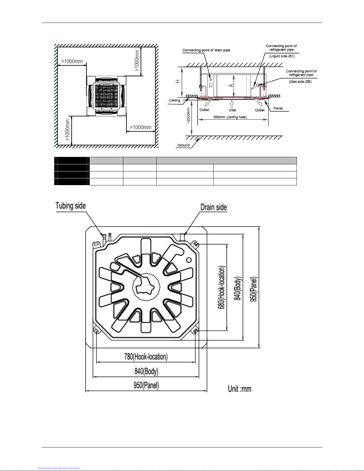
3.3 Super-slim cassette indoor unit installation
3.3.1 Service space for indoor unit
Model A H Remark
18-30 205 >235 R410A and R22 Cooling / Cooling & Heating
36-48 245 >275 R410A and R22 Cooling / Cooling & Heating
48-60 287 >317 R410A and R22 Cooling / Cooling & Heating
3.3.2 Bolt pitch
3.3.3 Install the pendant bolt
Select the position of installation hooks according to the hook holes positions showed in upper picture.
Drill four holes of Ø12mm, 45~50mm deep at the selected positions on the ceiling. Then embed the
expansible hooks (fittings).

Indoor unit installation
88 Installation
3.3.4 Install the main body
Make the 4 suspender through the 4 hanger of the main body to suspend it. Adjust the hexangular nuts on
the four installation hooks evenly, to ensure the balance of the body. Use a leveling instrument to make sure
the levelness of the main body is within ±1°.
Adjust the position to ensure the gaps between the body and the four sides of ceiling are even. The body's
lower part should sink into the ceiling for 10~12 mm. In general, L is half of the screw length of the
installation hook.
Locate the air conditioner firmly by wrenching the nuts after having adjusted the body's position well.
3.3.5 Install the panel
Remove the grille

Insulation Work
Installation 89
Remove the 4 corner covers.
Hang the panel to the hooks on the mainbody. If the panel is with auto-lift grille, please watch the ropes lifing
the grille, DO NOT make the ropes enwinded or blocked.
Tighten the screws under the panel hooks till the panel closely stick on the ceiling to avoid condensate
water.

Indoor unit installation
90 Installation
Hang the air-in grill to the panel, then connect the lead terminator of the swing motor and that of the control
box with corresponding terminators on the body respectively.
Install the 4 corner covers back.
Note: The panel shall be installed after the wiring connected.

Insulation Work
Installation 91
3.4 HESP duct indoor unit installation
3.4.1 Service space for indoor unit
500mm or more
600mm or more
Indoor unit
600mmx600mm
Maintenance and repair space
3.4.2 Bolt pitch
Capacity
(KBtu)
Size of mounted lug
D E
24 397 1146

Indoor unit installation
92 Installation
3.4.3 Install the pendant bolt
Select the position of installation hooks according to the hook holes positions showed in upper picture.
Drill four holes of Ø12mm, 45~50mm deep at the selected positions on the ceiling. Then embed the
expansible hooks (fittings).
3.4.4 Install the main body
Make the 4 suspender through the 4 hanger of the main body to suspend it. Adjust the hexangular nuts on
the four installation hooks evenly, to ensure the balance of the body. Use a leveling instrument to make sure
the levelness of the main body is within ±1°.
3.4.5 Install the air duct
Please design the air duct as below recommended picture

Insulation Work
Installation 93
4. Outdoor unit installation (Side Discharge Unit)
4.1 Service space for outdoor unit
4.2 Bolt pitch
Model B C D
MOU-18HN1-Q 530 290 315
MOU-24HN1-Q
560 335 360
MOU-30HN1-Q 624 366 396
MOU-30HN1-R 624 366 396
MOU-36HN1-Q
624 366 396

Outdoor unit installation (Side Discharge Unit)
94 Installation
MOU-36HN1-R 624 366 396
MOU-48HN1-R
590 378 400
MOUA-60HN1-R 590 378 400
4.3 Install the Unit
Since the gravity center of the unit is not at its physical center, so please be careful when lifting it with a sling.
Never hold the inlet of the outdoor unit to prevent it from deforming.
Do not touch the fan with hands or other objects.
Do not lean it more than 45, and do not lay it sidelong.
Make concrete foundation according to the specifications of the outdoor units.
Fasten the feet of this unit with bolts firmly to prevent it from collapsing in case of earthquake or strong wind.

Insulation Work
Installation 95
5. Refrigerant pipe installation
5.1 Maximum pipe length and height drop
Considering the allowable pipe length and height drop to decide the installation position. Make sure the
distance and height drop between indoor and outdoor unit not exceeded the date in the following table.
Model Max. Length Max. Elevation
18,000Btu/h ~24,000Btu/h 25m 12m
30,000Btu/h 25m 15m
36,000Btu/h 30m 20m
48,000Btu/h~60,000Btu/h 50m 25m
5.2 The procedure of connecting pipes
5.2.1 Choose the pipe size according to the specification table.
5.2.2 Confirm the cross way of the pipes.
5.2.3 Measure the necessary pipe length.
5.2.4 Cut the selected pipe with pipe cutter
Make the section flat and smooth.
90
Lean
Crude
Burr
o
5.2.5 Insulate the copper pipe
Before test operation, the joint parts should not be heat insulated.
5.2.6 Flare the pipe
Insert a flare nut into the pipe before flaring the pipe
According to the following table to flare the pipe
Pipe diameter
Flare dimension A (mm)
Flare shape
Min Max
1/4" (6.35) 8.3 8.7
R0.4~0.8
A
4
5
°
90°
4
-
+
3/8" (9.52) 12.0 12.4
1/2" (12.7) 15.4 15.8
5/8" (15.9) 18.6 19.1
3/4" (19) 22.9 23.3
After flared the pipe, the opening part must be seal by end cover or adhesive tape to avoid duct or
exogenous impurity come into the pipe.
5.2.7 Drill holes if the pipes need to pass the wall.
5.2.8 According to the field condition to bend the pipes so that it can pass the wall smoothly.
5.2.9 Bind and wrap the wire together with the insulated pipe if necessary.

Drainage pipe installation
96 Installation
5.2.10 Set the wall conduit
5.2.11 Set the supporter for the pipe.
5.2.12 Locate the pipe and fix it by supporter
For horizontal refrigerant pipe, the distance between supporters should not be exceed 1m.
For vertical refrigerant pipe, the distance between supporters should not be exceed 1.5m.
5.2.13 Connect the pipe to indoor unit and outdoor unit by using two spanners.
Be sure to use two spanners and proper torque to fasten the nut, too large torque will damage the
bellmouthing, and too small torque may cause leakage. Refer the following table for different pipe
connection.
Pipe Diameter
Torque Sketch map
(kgf.cm) (N.cm)
1/4" (6.35) 144~176 1420~1720
3/8" (9.52) 333~407 3270~3990
1/2" (12.7) 504~616 4950~6030
5/8" (15.9) 630~770 6180~7540
3/4" (19) 990~1210 9270~11860
6. Drainage pipe installation
Install the drainage pipe as shown below and take measures against condensation. Improperly installation
could lead to leakage and eventually wet furniture and belongings.
6.1 Installation principle
Ensure at least 1/100 slope of the drainage pipe
Adopt suitable pipe diameter
Adopt nearby condensate water discharge
6.2 Key points of drainage water pipe installation
6.2.1 Considering the pipeline route and elevation
Before installing condensate water pipeline, determine its route and elevation to avoid intersection with
other pipelines and ensure slope is straight.
6.2.2 Drainage pipe selection
The drainage pipe diameter shall not small than the drain hose of indoor unit
According to the water flowrate and drainage pipe slope to choose the suitable pipe, the water flowrate
is decided by the capacity of indoor unit.
Relationship between water flowrate and capacity of indoor unit
Capacity (x1000Btu) Water flowrate (l/h)
12 2.4
18 4
24 6
30 7
36 8
42 10
48 12
60 14
 Loading...