

OPERATING AND INSTALLATION MANUAL
I - VENTILCONVETTORE A PARETE
GB - WALL-MOUNTED FAN COIL
FR - VENTILO-CONVECTEUR MURAL
DE - WAND-GEBLÄSEKONVEKTOR
ES - VENTILOCONVECTOR DE PARED
I) Vi preghiamo di leggere con attenzione
il presente manuale prima di mettere in
funzione l’apparecchio.
GB) Please read this guide carefully before
switching on the appliance.
FR) Nous vous prions de bien vouloir lire
attentivement ce mode d'emploi avant
de mettre l'appareil en fonction.
DE) Bitte lesen Sie vor der Inbetriebnahme
des Geräts aufmerksam diese
Bedienungsanleitung.
ES) Les rogamos lean con atención el
presente manual antes de encender el
aparato.
MODELLI
MODELS
MODÈLES
MODELLE
MODELOS
MHD 30
MHD 40
MHD 50
MHD 60

1
GENERALE
Avvertenze generali pagina 2
Regole fondamentali di sicurezza 2
Composizione della fornitura 3
Ricevimento del prodotto e movimentazione 3
Dati tecnic 4
Accesso alle connessioni 4
Schemi elettrici 5
INSTALLATORE
Installazione 6
Collegamenti 7
Montaggio dei filtri depuratori 10
Prima messa in servizio 10
Caricamento e svuotamento dell’impianto 11
UTENTE
Telecomando a raggi infrarossi 12
Telecomando a raggi infrarossi: modalita’ funzionamento
12
Programmazione del timer 15
Funzione sleep 15
Funzionamento telecomando a infrarossi 16
Regolazione flusso aria 16
Operazioni di emergenza 17
Manutenzione 18
ASSISTENZA TECNICA
Manutenzione 19
Eventuali anomalie e rimedi 19
GAMMA
INDICE
Per informazioni relative all’assistenza tecnica e al reperimento delle parti di ricambio potete contattare:
ASSISTENZA TECNICA CLIMAVENETA
via Duca d'Aosta 121, 31100, Mignagola - Treviso (ITALY)
Tel +39 0422 4131 Fax +39 0422 413659
www.climaveneta.it - info@climavenetahs.it
Funzionamento in raffreddamento: Temperatura ambiente a 27°C b.s./ 19°C b.u., acqua refrigerata entrante a 7°C e uscente a 12°C
INFORMAZIONI UTILI
I ventilconvettori sono apparecchi dedicati ad utenze civili di
elevato livello qualitativo. L’eleganza del disegno estetico, l’elettronica di gestione e la componentistica di prim’ordine consentono facile ambientabilità ed elevato livello di comfort.
UNITÀ INTERNA
• Mobile di copertura costituito da materiale plastico autoe-
stinguente
• Gruppo elettroventilante:
ventola tangenziale direttamente accoppiata al motore
elettrico 3 velocità di ventilazione e funzione auto
• Batteria di scambio costituita da tubi di rame turbolenziati
e alette di alluminio.
• Scheda di controllo microprocessore
• Sistemi filtranti
TELECOMANDO
Il controllo, la regolazione e la programmazione vengono
effettuate con il telecomando a raggi infrarossi, le cui modalità
funzionali e di impiego sono descritte nel manuale utente.
Le immagini delle unità sono puramente rappresentative e possono avere delle differenze rispetto il fan coil
MHD consegnato.
DESCRIZIONE DELL’APPARECCHIO
Fan coil murale Potenza frigorifera
MHD 30 2,2 kW
MHD 40 2,9 kW
MHD 50 4,0 kW
MHD 60 4,8 kW
In alcune parti del libretto sono utilizzati i simboli:
ATTENZIONE:
per azioni che richiedono particolare cautela ed adeguata preparazione.
VIETATO:
per azioni che NON DEVONO essere assolutamente
eseguite.
AVVERTENZE GENERALI Generale
2
REGOLE FONDAMENTALI DI SICUREZZA Generale
Dopo aver tolto l’imballo assicurarsi dell’integrità e della
completezza del contenuto. In caso di non rispondenza
rivolgersi all’Agenzia che ha venduto l’apparecchio.
L’installazione degli apparecchi deve essere effettuata
da impresa abilitata ai sensi della Legge 5 Marzo 1990
n° 46 che, a fine lavoro, rilasci al proprietario la dichiarazione di conformità di installazione realizzata a regola
d’arte, cioè in ottemperanza alle Norme vigenti e alle
indicazioni fornite dalla nel libretto d’istruzioni a corredo
dell’apparecchio.
Questi apparecchi sono stati realizzati per il condizionamento e il riscaldamento degli ambienti e dovranno
essere destinati a questo uso compatibilmente con le
loro caratteristiche prestazionali.
È esclusa qualsiasi responsabilità contrattuale ed extracontrattuale dell’Azienda per danni causati a persone,
animali o cose, da errori d’installazione, di regolazione e
di manutenzione o da usi impropri.
Evitare che il locale rimanga chiuso a lungo. Periodicamente aprire le finestre per assicurare un corretto ricambio d’aria.
Una temperatura troppo bassa è dannosa alla salute e
costituisce un inutile spreco di energia.
Evitare il contatto diretto con il flusso dell’aria per un
periodo prolungato.
Durante i temporali posizionare l’interruttore generale
dell’impianto su “spento”.
Questo libretto deve essere conservato con cura perché
è parte integrante dell’apparecchio e di conseguenza
dovrà SEMPRE accompagnarlo anche in caso di sua
cessione ad altro proprietario o utente, oppure di un trasferimento su un altro impianto.
In caso di suo danneggiamento o smarrimento richiederne un'altra copia al Servizio Tecnico di Assistenza di
zona.
Gli interventi di riparazione o manutenzione devono
essere eseguiti dal Servizio Tecnico di Assistenza o da
personale qualificato secondo quanto previsto dal presente libretto. Non modificare o manomettere l’apparecchio in quanto si possono creare situazioni di pericolo ed
il costruttore dell’apparecchio non sarà responsabile di
eventuali danni provocati.
Nel caso di installazioni Caldo/Freddo l’acqua che circola nella batteria non deve superare i 60°C.
Il fan coil deve essere installato ad un'altezza minima di
2,5 metri rispetto al suolo.
Ricordiamo che l’utilizzo di prodotti che impiegano energia
elettrica comporta l’osservanza di alcune regole fondamentali di sicurezza quali:
È vietato l’uso del climatizzatore ai bambini e alle persone inabili non assistite.
È vietato, toccare l’apparecchio se si è a piedi nudi e con
parti del corpo bagnate.
È vietato qualsiasi intervento tecnico o di pulizia, prima
di aver scollegato l’apparecchio dalla rete di alimentazione elettrica posizionando l’interruttore generale dell’impianto su “spento”.
È vietato modificare i dispositivi di sicurezza o di regolazione senza l’autorizzazione e le indicazioni del costruttore dell’apparecchio.
È vietato tirare, staccare, torcere i cavi elettrici fuoriuscenti dall’apparecchio anche se questo è scollegato
dalla rete di alimentazione elettrica.
È vietato salire con i piedi sull’apparecchio e/o appoggiarvi qualsiasi tipo di oggetto.
È vietato spruzzare o gettare acqua direttamente sull’apparecchio.
È vietato introdurre oggetti appuntiti attraverso le griglie
di aspirazione e mandata aria.
È vietato aprire gli sportelli di accesso alle parti interne
dell’apparecchio, senza aver prima posizionato l’interruttore generale dell’impianto su “spento”.
È vietato disperdere, abbandonare o lasciare alla portata
di bambini il materiale dell’imballo in quanto può essere
potenziale fonte di pericolo.
E' vietato l'uso del ventilconvettore a persone le cui
capacità fisiche, sensoriali o mentali siano ridotte, oppure in mancanza di esperienza o di conoscenza. Possono
utilizzare l'apparecchio solo se abbiano potuto beneficiare, attraverso l'intermediazione di una persona responsabile della loro sicurezza, di una sorveglianza o di istruzioni specifiche riguardanti l'uso del fan coil.
3
COMPOSIZIONE DELLA FORNITURA Generale
Il ventilconvettore viene fornito in un collo protetto da un
imballo in cartone ed è corredato di:
- Libretto istruzione utente/installatore
- Certificato di garanzia
che sono inseriti in buste di plastica all’interno dell’imballo
dell’unità interna.
I libretti d’istruzione sono parte integrante dell’apparecchio e quindi si raccomanda di leggerli e di conservarli
con cura.
RICEVIMENTO DEL PRODOTTO E MOVIMENTAZIONE Generale
I ventilconvettori vengono forniti in collo unico protetti da un
imballo in cartone.
È consigliato togliere l’imballo solo quando l’apparecchio
è stato posizionato in prossimità del punto d’installazione. Tolto l’imballo, la movimentazione del ventilconvettore deve essere effettuata manualmente da personale
qualificato adeguatamente equipaggiato e nel rispetto
delle norme antinfortunistiche.
La movimentazione del ventilconvettore deve essere
effettuata da personale qualificato adeguatamente equipaggiato e con attrezzature idonee al peso dell’apparecchio.
Rimuovere con cautela le striscie adesive posizionate
sull’apparecchio.
È vietato disperdere nell’ambiente le parti dell’imballo, o
lasciarle alla portata dei bambini in quanto potenziale
fonte di pericolo.
È vietato disperdere nell’ambiente le parti dell’imballo, o
lasciarle alla portata dei bambini in quanto potenziale
fonte di pericolo.
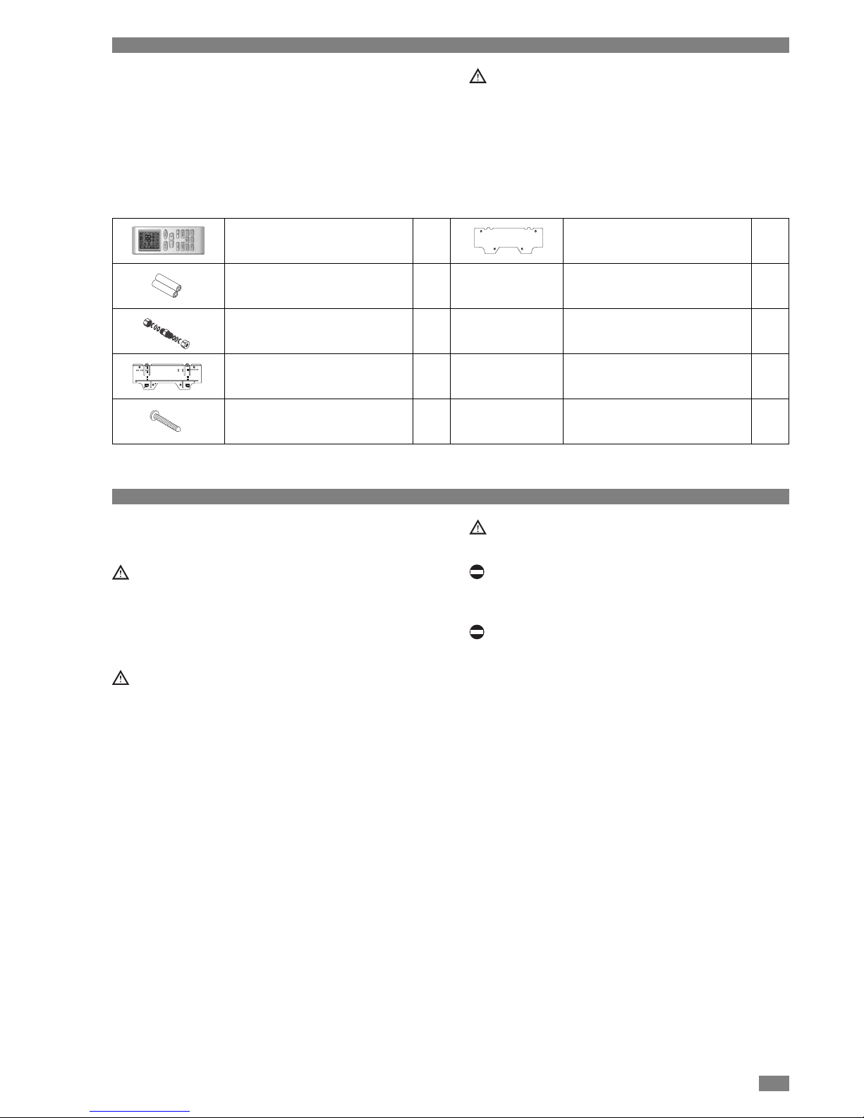
Telecomando 1
Batterie del tipo AAA 2
Elementi per giunto rapido 2
Supporto metallico 1
Viti (4,1x32) per supporto metallico 5
Dima di carta per installazione 1
4
Agire con cautela nella rimozione del coperchio
di protezione degli indicatori luminosi.
Vista posteriore
Collegamento elettrico
valvola acqua
Ingresso alimentazione
elettrica
Morsettiera
Pressacavo
CONNESSIONI ELETTRICHE
ACCESSO ALLE CONNESSIONI Generale
DATI TECNICI Generale
Modelli MHD 30 MHD 40 MHD 50 MHD 60
Portata d’aria
Vel. Max m3/h 436 632 780 920
Vel. Med m3/h 376 522 691 810
Vel. Min m3/h 334 403 570 697
Potenza totale in raffreddamento (1)
Vel. Max 1 kW 2,15 2,8 4 4,7
Vel. Med 1 kW 1,85 2 3,4 3,9
Vel. Min 1 kW 1,65 1,75 3,1 3,35
Potenza sensibile in raffreddamento (1)
Vel. Max 1 kW 1,82 2,48 3,4 3,6
Vel. Med 1 kW 1,6 1,75 2,9 3,3
Vel. Min 1 kW 1,45 1,55 2,6 2,85
Perdita di carico Max (1) 1 kPa 10 16 37 46
Potenza totale in riscaldamento (2)
Vel. Max 2 kW 2,7 3,6 4,9 5,8
Vel. Med 2 kW 2,3 2,55 4,2 4,85
Vel. Min 2 kW 1,98 2,2 3,8 4,15
Perdita di carico Max (2) 2 kPa 9 15 35 44
Potenza sonora (3)
Vel. Max 3 dB(A) 45 52 55 60
Vel. Med 3 dB(A) 42 42 52 56
Vel. Min 3 dB(A) 38 39 48 53
Connessioni acqua ingresso mm 12 12 12 12
Connessioni acqua uscita mm 12 12 12 12
Potenza assorbita Max W 24 28 40 50
Corrente assorbita Max A 0,25 0,26 0,34 0,35
Alimentazione elettrica V-Ph~Hz 230V~50Hz 230V~50Hz 230V~50Hz 230V~50Hz
DIMENSIONI UNITA'
W mm 845 845 920 920
H mm 270 270 298 298
D mm 180 180 200 200
Peso kg 10 10 13 13
DIMENSIONI IMBALLO
W mm 920 920 1020 1020
H mm 360 360 388 388
D mm 260 260 290 290
W
D
H
Note
(1) Funzionamento in raffreddamento: Temperatura ambiente a 27°C b.s./ 19°C b.u., acqua refrigerata entrante a 7°C e uscente a 12°C
(2) Funzionamento in riscaldamento: Temperatura ambiente a 20°C b.s., acqua calda entrante a 50°C, con portata identica a quella in modalità raffreddamento
(3) Potenza sonora
W
D
H
5
Attacco acqua IN
Attacco acqua OUT
Attacco scarico condensa
Vista posteriore
CONNESSIONI IDRAULICHE
SCHEMI ELETTRICI Generale
MHD 30-40
MHD 50-60
6
Fori per viti
di fissagio
Foro per il passaggio deitubi
dei cavi elettrici e del
tubo di scarico condensa
4,1x32
INSTALLAZIONE Installatore
LOCATING THE INDOOR UNIT
Il luogo dell’installazione deve essere stabilito dal progettista
dell’impianto o da persona competente in materia e deve
tenere conto delle esigenze tecniche, Norme e Legislazioni
vigenti.
L’installazione del ventilconvettore deve essere effettuata da
impresa abilitata ai sensi della Legge 5 marzo 1990.
I ventilconvettori sono previsti per installazione a parete.
La loro ubicazione deve essere tale da permettere la circolazione dell’aria trattata in tutto l’ambiente, e il rispetto degli
spazi minimi necessari per gli interventi tecnici e di manutenzione.
Prima di iniziare l’installazione stabilire il posizionamento
dell’unità interna e dell’unità esterna in considerazione
degli spazi tecnici minimi, della lunghezza max delle
linee frigorifere e del dislivello tra gli apparecchi..
Per installare l’unità alla parete:
- Fissare il supporto metallico alla parete utilizzando i tasselli ad espansione e le viti forniti a corredo.
DIMA D’INSTALLAZIONE
MHD 30-40
Fori per viti
di fissagio
Foro per il passaggio deitubi
dei cavi elettrici e del
tubo di scarico condensa
MHD 50-60
7
Pretranciati
2~5 mm
Esterno
Interno
Tubo di protezione
A
COLLEGAMENTO SCARICO ACQUA DI CONDENSA
L’unità interna è provvista di tubo di scarico condensa al
quale va collegato un condotto di drenaggio da indirizzare
verso un luogo adatto allo scarico. L’apparecchio è predisposto per lo scarico condensa sia a sinistra che a destra, il
tubo di scarico è collegato di fabbrica a destra.
- Rimuovere il pannello frontale come descritto nella sezione: Manutenzione.
- Utilizzare un utensile per rimuovere la molla di fissaggio
presente nel tubo scarico condensa.
- Rimuovere il tappo presente.
- Posizionare la molla di fissaggio nel tubo di scarico a
destra dell'unità.
- Riposizionare il pannello frontale procedendo in modo
inverso.
Collegare un condotto di drenaggio isolato (ø interno 16
mm) al portagomma del tubo di scarico e indirizzarlo verso un luogo idoneo allo scarico
Dopo l’installazione verificare il regolare deflusso della
condensa.
Per i dati relativi all’installazione far riferimento al capitolo “Informazioni per l’installazione”.
Per l’accesso alle connessioni far riferimento al capitolo
“Accesso alle connessioni”.
Il tubo di drenaggio deve avere una pendenza del 3%
verso il luogo di scarico evitando tratti in contrpendenza.
Accertarsi della buona tenuta di tutte le giunzioni per evitare fuoriuscite di acqua.
Applicare dell’isolante termico sui punti di giunzione.
COLLEGAMENTO ALL’IMPIANTO IDRAULICO
In caso di uscita dei collegamenti nelle posizioni laterali:
- Rimuovere la parte necessaria di pretranciato dal mobile
di copertura.
In caso di uscita dei collegamenti nelle posizioni posteriori:
- Praticare un foro Ø 60 nella parete, all’interno di una delle
due aree “A” (vedi capitolo “Informazioni per l’installazione”).
Inserire nel foro, praticato nel muro, un tubo di plastica di
protezione.
Assicurarsi che il tratto di parete non interessi elementi
portanti della costruzione, tubazioni o linee elettriche.
Al termine dei lavori è consigliato chiudere i fori di passaggio realizzati nel muro con materiale elastico e possibilmente fonoassorbente.
- Per facilitare i collegamenti idraulici tenere sollevata l’unità
utilizzando un distanziale.
- In caso di necessità posizionare i collegamenti nel vano
sul retro dell’unità interna e fissarli con la staffa di supporto A fornita a corredo.
Posizionare i tubi in modo che occupino il minor spazio
possibile per favorire l’aggancio dell’apparecchio al supporto metallico.
COLLEGAMENTI Installatore
8
Agganciare qui
1
2
3
4
5
La scelta e l’installazione dei componenti dell’impianto è
demandato per competenza all’installatore, che dovrà
operare secondo le regole della buona tecnica e della
Legislazione vigente.
Gli impianti caricati con antigelo obbligano l’impiego di
disconnettori idrici.
Acque di alimentazione/reintegro particolari, vanno condizionate con opportuni sistemi di trattamento. Come
valori di riferimento possono essere considerati quelli
riportati in tabella.
Evitare di stringere troppo il nastro adesivo per non danneggiare l’isolamento.
Per effettuare i collegamenti idraulici
- Agganciare il ventilconvettore al supporto metallico tenendo sollevato il bordo inferiore.
- Posizionare le linee idrauliche.
- Pulire le superfici dei raccordi e le estremità delle linee.
- Posizionare i giunti di collegamento forniti a corredo sulle
estremità delle linee idrauliche e sugli attacchi del ventilconvettore.
- Serrare adeguatamente i giunti di collegamento.
- Posizionare sulle giunzioni del materiale isolante, fissandolo con del nastro adesivo per non danneggiare l’isolamento.
- Agganciare il ventilconvettore al supporto metallico.
VALORI DI RIFERIMENTO H2O
pH 6-8
Conduttività elettrica minore di 200 mV/cm (25°C)
Ioni cloro minore di 50 ppm
Ioni acido solforico minore di 50 ppm
Ferro totale minore di 0,3 ppm
Alcalinità M minore di 50 ppm
Durezza totale minore di 35 °f
Ioni zolfo nessuno
Ioni ammoniaca nessuno
Ioni silicio minore di 30 ppm
Collegamenti eseguiti
in fabbrica
Collegamenti a cura
dell’installatore
Uscita
Ingresso
3
1
2
4
5
54
1 Ventilatore
2 Scambiatore di calore
3 Sfiato aria manuale
4 Giunto di collegamento
(fornito a corredo)
5 Valvola di intercettazione a sfera
9
ELECTRICAL CONNECTIONS
Il ventilconvettore lascia la fabbrica completamente cablato
e necessita solamente di:
- collegamento alla rete di alimentazione elettrica.
Per qualsiasi intervento di natura elettrica fare riferimento al capitolo “Schemi elettrici”.
Verificare che:
- Le caratteristiche della rete elettrica siano adeguate
agli assorbimenti massimi indicati nella tabella riportata
al Capitolo “Dati tecnici”, considerando anche eventuali
altri macchinari in funzionamento parallelo.
- La tensione di alimentazione elettrica corrisponda al
valore nominale +/- 10%.
È obbligatorio:
- L’impiego di un interruttore magnetotermico onnipolare,
sezionatore di linea, conforme alle Norme CEI-EN
(apertura dei contatti di almeno 3 mm), installato in
prossimità dell’apparecchio
- Realizzare un efficace collegamento a terra.
Il costruttore non è responsabile di eventuali danni causati dalla mancata di messa a terra o dall’inosservanza
di quanto riportato negli schemi elettrici.
È vietato l’uso dei tubi del gas e dell’acqua per la messa
a terra dell’apparecchio.
Per l’accesso alle connessioni far riferimento al capitolo
“Accesso alle connessioni”.
ALIMENTAZIONE ELETTRICA
- Eseguire i collegamenti come indicato in figura.
L’unità è provvista di cavo di alimentazione per una lunghezza pari a 1,6 m.
L’interruttore ON-OFF dell’unità deve essere posizionato
in OFF.
- Terminati i collegamenti fissare i cavi con i pressacavi e
riposizionare i coperchi delle morsettiere.
10
MONTAGGIO DEI FILTRI DEPURATORI Installatore
A corredo del ventilconvettore vengono forniti filtri depuratori
d’aria in grado di assorbire microscopiche particelle di polvere, pollini e muffe.
Per l’istallazione procedere come segue:
- Posizionare l’interruttore generale dell’impianto su “spento”
L’installazione del filtro depuratore riduce la portata dell’aria con conseguente riduzione della capacità di raffreddamento e di riscaldamento. In questo caso si consiglia di utilizzare il climatizzatore alla MEDIA o alla ALTA
velocità.
Pulire i filtri aria ogni 2 settimane.
Mantenere i filtri depuratori sigillati fino al momento del
loro utilizzo.
Durante l’inserimento dei filtri depuratori evitare contatti
con la batteria di scambio o utilizzare adeguate protezioni antinfortunistiche.
PRIMA MESSA IN SERVIZIO Installatore
Prima di effettuare l’avviamento ed il collaudo funzionale del
ventilconvettore è indispensabile che:
- Tutte le condizioni di sicurezza siano state rispettate
- L’apparecchio sia posizionato correttamente
- I collegamenti elettrici, frigoriferi e dello scarico condensa
siano stati effettuati correttamente
- Le valvole di intercettazione siano aperte.
Quindi:
- Posizionare l’interruttore generale dell’impianto su “acceso”
MHD Modello
- Attivare il ventilconvettore con il telecomando
- Verificare il funzionamento nelle diverse modalità
- Verificare le velocità di funzionamento del ventilatore.
Per le modalità d’impiego del telecomando far riferimento
alle istruzioni contenute nel manuale Utente.
RIAVVIAMENTO AUTOMATICO
Il ventilconvettore è dotato di un dispositivo che consente il
riavviamento automatico in caso di interruzione dell’alimentazione elettrica e successivo ripristino.
Il ventilconvettore si riavvia nella modalità di funzionamento precedentemente impostata.
ACCESO
SPENTO
11
CARICAMENTO E SVUOTAMENTO DELL’IMPIANTO Installatore
CARICAMENTO
- Prima di iniziare il caricamento posizionare l’interruttore
generale dell’impianto su “spento”
- Verificare che il rubinetto di scarico impianto sia chiuso
- Rimuovere il pannello frontale
- Aprire la valvola di sfiato del ventilconvettore e dell’impianto (vedi figura)
- Iniziare il riempimento aprendo lentamente il rubinetto di
carico acqua impianto all’esterno dell’apparecchio
- Quando comincia ad uscire acqua dalla valvola di sfiato,
chiuderla immediatamente e continuare il caricamento fino
al valore di pressione previsto per l’impianto.
Verificare l’assenza di perdite della valvola stessa.
Verificare la tenuta idraulica della giunzioni.
Si consiglia di ripetere questa operazione dopo che l’apparecchio ha funzionato per alcune ore e di controllare
periodicamente la pressione dell’impianto.
Questa operazione deve essere effettuata da personale
tecnico specializzato.
SVUOTAMENTO
- Prima di iniziare lo svuotamento posizionare l’interruttore
generale dell’impianto su “spento”.
- Verificare che il rubinetto di carico impianto sia chiuso.
- Aprire la valvola di sfiato del ventilconvettore e dell’impianto.
Se l’impianto è addizionato con liquido antigelo, quest’ultimo non va scaricato liberamente perché inquinante.
Deve essere raccolto ed eventualmente riutilizzato. Questa operazione deve essere effettuata da personale tecnico specializzato.
ACCESO
SPENTO
ACCESO
SPENTO

12
Segnale trasmissione
TELECOMANDO A RAGGI INFRAROSSI Utente
A. ON/OFF
Premere il pulsante per l’accensione dell’unità. Premere
nuovamente il pulsante per lo spegnimento. Durante l’accensione e lo spegnimento del fan coil, le funzioni Timer
e Sleep impostate verranno cancellate.
B. MODE
La pressione ripetuta permette la selezione di: Auto, Cool,
Deumidificazione, Fan, Heat. La funzione Fan, impostata di
default all’accensione dell’unità, la temperatura aria non
può essere impostata (24°C – 75°F). In funzione Heat, il
valore iniziale è pari a 28°C (82°F). Per le altre modalità di
funzionamento il valore iniziale è pari a 25°C (77°F).
C. SLEEP
All’accensione dell’unità, la funzione Sleep è spenta.
Quando viene attivata la funzione Sleep il corrispettivo
simbolo verrà visualizzato nel display. E’ possibile impostare il tempo di spegnimento automatico. In modalità
Fan e Auto, questa funzione è disabilitata..
D. FAN
Le velocità possono essere selezionate circolarmente.
All’accensione dell’unità è impostata la velocità Auto. In
funzione Deumidificazione l’unità funzionerà alla minima
velocità.
E. CLOCK
Premere il pulsante per impostare l’ora. Il simbolo inizierà a lampeggiare. Entro 5 secondi il valore può essere
modificato premendo (pulsanti + o -). Durante il lampeggio premere il pulsante (simbolo orologio), l’icona smetterà di lampeggiare a conferma dell’avvenuta impostazione. Al momento della prima accensione è impostato il
seguente orario 12:00 ed il simbolo viene visualizzato.
Se è visualizzato, il valore indicato corrisponde all’ora impostata, altrimenti corrisponde
alla funzione Timer.
F. LIGHT
Premere il pulsante per accendere o spegnere la luce
del display. Quando il display è illuminato, l’icona (simbolo light) è visualizzata. Quando la luce display è spenta,
l’icona non viene visualizzata.
G.
Premere il pulsante per incrementare la temperatura
impostata. Tenendo premuto il pulsante per almeno 2
secondi, la temperatura incrementerà rapidamente. In
funzione Auto la temperatura non può essere impostata.
Scala set point selezionabile (16-30 °C / 61-86 °F).
Per il corretto funzionamento del telecomando è necessario
che non ci siano ostruzioni tra esso ed il ricevitore situato
nel fan coil. Non lanciare o far cadere il telecomando per
possibile causa guasti. Non versare liquidi sopra il telecomando. Non posizione il telecomando a contatto diretto con
i raggi del sole o a contatto con fonti dirette di calore.
Simboli
AUTO
COOL
DRY
FAN
HEAT
Low FAN
Middle FAN
High FAN
Clock
Light
Sleep
Temp
Padlock
A
D
E
C
B
HG
L
M
N
F
I
AUTO
AUTO

13
H.
Premere il pulsante per decrementare la temperatura
impostata. Tenendo premuto il pulsante per almeno 2
secondi, la temperatura decrementerà rapidamente. In
funzione Auto la temperatura non può essere impostata.
I. TEMP
Dopo l’accensione del fan coil, viene visualizzata la temperatura impostata dall’utente. Premere il pulsante : il
simbolo indica la temperatura impostata; mentre il simbolo indicata la temperatura aria ambiente. Il telecomando visualizza inizialmente la temperatura impostata,
dopo 5 secondi circa, verrà visualizzata la temperatura
ambiente.
L. SWING UP AND DOWN
Premere il pulsante per impostare posizione deflettori
come indicato nello schema seguente.
M. TIMER ON
Impostazione Timer. Premere il pulsante TIMER ON. Il
simbolo ON lampeggerà nel display, mentre il
simbolo verrà nascosto. L’ora indicata nel telecomando corrisponde al timer di accensione. Impostare l’orario
di accensione desiderato premendo i pulsanti + e -. Una
volta definito l’orario di accensione, premere nuovamente
il pulsante TIMER ON per confermare.
N. TIMER OFF
Premere il pulsante TIMER OFF per impostare lo spegnimento dell’unità, il simbolo OFF icona inizierà a lampeggiare. La modalità di impostazione TIMER OFF è la
medesima di TIMER ON
OFF
TELECOMANDO A RAGGI INFRAROSSI: MODALITA’ FUNZIONAMENTO Utente
Selezione modalità di funzionamento
Premendo il pulsante MODE è possibile selezionare modalità di funzionamento con il seguente ordine: AUTO – COOL
– DEUMIDIFICAZIONE – FAN – HEAT
La modalità riscaldamento non è attiva nelle installazioni
dedicate al solo raffreddamento.
L’unità è un terminale idronico e la sua modalità di funzionamento dipende dal chiller o dal boiler a cui è stato
collegato.
In modalità riscaldamento, l’unità inizierà ad operare
solo quando la temperatura in batteria ha raggiunto temperatura sufficientemente alta.
Range di temperatura impostabili:
* Solo per installazioni che offrono questa modalità di fun-
zionamento.
Heating* 16°C ~ 30°C
Cooling 16°C ~ 30°C
Dehumidifying/dry Temperatura ambiente ± 2°C
Fan

14
SELEZIONE MODALITA’ COOLING
• Premere per accendere il fan coil.
Il simbolo inizierà a lampeggiare ed un segnale acustico definisce l’accensione del fan coil.
• Press the MODE button repeatedly until the cooling
symbol appears on the display.
• Premere il pulsante MODE fino a che viene visualizzato il
simbolo .
• Impostare la temperatura desiderata utilizzando i pulsanti
().
• Impostare la velocità desiderata premendo il pulsante
FAN.
In modalità cooling, l’unità sottrae automaticamente l’umidità in eccesso dall’ambiente.
SELEZIONE MODALITA’ DEUMIDIFICAZIONE
E’ consigliato attivare questa funzione quando il tasso di
umidità è elevato.
• Premere per accendere il fan coil.
• Il simbolo inizierà a lampeggiare ed un segnale acustico definisce l’accensione del fan coil.
• Premere il pulsante MODE fino a che viene visualizzato il
simbolo .
• Impostare la temperatura desiderata utilizzando i pulsanti
.
• La velocità del ventilatore è impostata automaticamente
dall’unità.
SELEZIONE MODALITA’ FAN
• Premere per accendere il fan coil.
• Il simbolo inizierà a lampeggiare ed un segnale acustico definisce l’accensione del fan coil.
• Premere il pulsante MODE fino a che viene visualizzato il
simbolo .
• Impostare la temperatura desiderata utilizzando i pulsanti
.
• Impostare la velocità desiderata premendo il pulsante
FAN.
SELEZIONE MODALITA’ HEAT
• Premere per accendere il fan coil.
• Il simbolo inizierà a lampeggiare ed un segnale acustico definisce l’accensione del fan coil.
• Premere il pulsante MODE fino a che viene visualizzato il
simbolo .
• Impostare la temperatura desiderata utilizzando i pulsanti
.
• Impostare la velocità desiderata premendo il pulsante
FAN.
ON/OFF
ON/OFF
ON/OFF
ON/OFF

15
PROGRAMMAZIONE DEL TIMER Utente
Dopo aver selezionato la modalità di funzionamento desiderata, accedere alla modalità timer come indicato nella sezione precedente. La funzione timer permette di programmare
il funzionamento dell’unità sulla base dell’effettiva presenza
nel locale da climatizzare.
Programmazione TIMER ON
• Dopo aver acceso l’unità premere il pulsante TIMER ON.
L’ora visualizzata nel display inizierà a lampeggiare. Impostare l’ora di accensione utilizzando i pulsanti .
• Premere nuovamente il pulsante TIMER ON per confermare.
• Quando l’ora impostata viene visualizzata, l’unità automaticamente si accenderà.
• Per cancellare l’ora di accensione impostata premere nuovamente il pulsante TIMER ON. Un segnale acustico confermerà l’avvenuta impostazione
Programmazione TIMER OFF.
• Dopo aver acceso l’unità premere il pulsante TIMER OFF.
L’ora visualizzata nel display inizierà a lampeggiare. Impostare l’ora di spegnimento utilizzando i pulsanti .
• Premere nuovamente il pulsante TIMER OFF per confermare.
• Quando l’ora impostata viene visualizzata, l’unità automaticamente si spegnerà.
• Per cancellare l’ora di spegnimento impostata premere
nuovamente il pulsante TIMER OFF. Un segnale acustico
confermerà l’avvenuta impostazione.
FUNZIONE SLEEP Utente
La funzione SLEEP può essere selezionata in modalità
Cooling, Heating e Deumidificazione. Questa funzione può
essere utilizzata per ottenere un ambiente più confortevole
durante il riposo notturno.
Funzione SLEEP:
• L’unità si spegne automaticamente dopo 8 ore di funzionamento;
• E’ impostata automaticamente la minima velocità di ventilazione;
• In modalità cooling, la temperatura impostata cresce di
1°C per ora, fino ad un massimo di 2 ore. Dopo di che il
set point rimane invariato;
• In modalità heating, la temperatura impostata decresce di
1°C per ora, fino ad un massimo di 2 ore. Dopo di che il
set point rimane invariato.
COOLING/DEHUMIDIFYING
1 hour
START
STOP
1 hour
timer 8 hours
1° increase
1° increase
SET
TEMPERATURE

FUNZIONAMENTO TELECOMANDO A RAGGI INFRAROSSI Utente
Lucchetto
Premere i pulsanti + e - contemporaneamente per bloccare
e sbloccare la tastiera telecomando. Se il telecomando è
bloccato il simbolo apparirà sul display.
Selezione scala temperatura
Ad unità spenta premere pulsante MODE e - per cambiare
la scala di temperatura da gradi Centigradi (°C) a Fahrenheit (°F).
Modalità inserimento batterie telecomando:
- Rimuovere lo sportellino telecomando seguendo la direzione indicata dalla freccia;
- Rimuovere le batterie esaurite;
- Inserire le nuove batterie (AAA 1,5V) ponendo attenzione
alla polarità;
- Riposizionare lo sportellino di chiusura;
NOTA:
- Non utilizzare batterie differenti da quelle indicate o riutilizzare quelle esaurite per possibile malfunzionamento telecomando.
- Se il telecomando non viene utilizzato per un lungo periodo, rimuovere le batterie per non lasciare che il liquido al
loro interno danneggi il dispositivo.
- Se il telecomando non funziona correttamente, rimuovere
momentaneamente le batterie, provare a inserirle nuovamente dopo 1 minuto circa. Se il malfunzionamento persiste, sostituire le batterie.
REGOLAZIONE FLUSSO ARIA Utente
Regolazione della portata aria
Il flusso aria verticale è automaticamente regolato ad una
certa angolazione in base alla modalità di funzionamento.
La direzione del flusso d’aria può essere regolata manualmente premendo il pulsante SWING sul telecomando.
Movimento del deflettore aria
Premere il pulsante SWING per regolare la posizione del
deflettore e del flusso aria.
Impostazione del flusso aria
Premere il pulsante SWING per bloccare il deflettore aria
alla posizione desiderata..
Regolazione manuale del flusso aria orizzontale
- Accertarsi che l’unità sia spenta;
- Spostare il cursore interno all’unità per posizionare i
deflettori orizzontali nella posizione desiderata;
Non manipolare la posizione del deflettore aria verticale
per possibile malfunzionamento unità. La posizione del
deflettore verticale è regolata dal telecomando. In caso di
necessità spegnere e riaccendere l’unità, il deflettore aria
verticale si posizionerà automaticamente nella migliore
posizione.
Non mantenere a lungo il deflettore verticale rivolto verso il basso, poiché in modalità Cool o Deumidificazione
è possibile caduta di condensa
Per regolare il flusso d’aria verticale,
premere il pulsante SWING.
Posizionamento cursore per regolare
flusso d’aria orizzontale
Cooling Posizione orizzontale
Deumidificazione Posizione orizzontale
Heating Posizione verso il basso
Fan Posizione verso il basso
16

17
OPERAZIONI DI EMERGENZA Utente
Illuminazione display per controllo funzionamento unità:
It's a special selective button for the users, who are not
accustomed to the light at sleeping.
- Accensione del display telecomando: premere il pulsante
LIGHT, il simbolo apparirà sul display;
- Spegnimento del display telecomando: premere il pulsante
LIGHT, il simbolo scomparirà dal display;
Operazioni di emergenza
- In caso di malfunzionamento o mancanza del telecomando, premere il pulsante di emergenza come indicato in
figura. L’unità funzionerà in modalità Fan, la temperatura e
la velocità del ventilatore non possono essere impostate;
- Per azionare l’unità con il pulsante di emergenza rimuovere il mantello unità come descritto nella sezione Manutenzione;
- Premere il pulsante di emergenza per almeno 3 secondi
con l’impiego di un utensile;

18
MANUTENZIONE Assistenza tecnica
Prima di effettuare ogni attività di manutenzione e pulizia
spegnere e scollegare l’unità dalla rete di alimentazione,
per possibile rischio di scossa elettrica
Non versare acqua sull’unità per possibile rischio di
scossa elettrica.
L’impiego di detersivi o diluenti può danneggiare l’unità.
Pulire il fan coil con un panno morbido asciutto o leggermente inumidito con acqua o detergente neutro.
Pulizia del pannello frontale
Durante la pulizia del pannello frontale, si prega di immergere il panno in acqua inferiore a 45 °C; strizzare il panno e
pulire la parte sporca dell’unità.
Pulizia del filtro aria
Se la polvere si deposita attorno l’unità, il filtro aria deve
essere pulito. Dopo aver rimosso il filtro aria non toccare le
alette della batteria per rischio di tagli alle dita. Si consiglia
di effettuare la pulizia dei filtri ogni 2 settimane.
1. Rimuovere i filtri aria
Rimuovere il pannello di copertura frontale. Rimuovere il
filtro aria come indicato in figura (a, b).
2 Pulire il filtro aria
Per rimuovere la polvere dal filtro aria è possibile utilizzare un aspirapolvere o lavare con acqua calda (temperatura inferiore 45 °C) e con detergente neutro. Asciugare il
filtro aria all'ombra.
Nota: Non usare mai acqua superiore a 45 °C per la pulizia; è possibile causare la deformazione del filtro. Non
asciugare il filtro a contatto diretto con fiamme o fonti di
calore. Possibile rischio di deformazione o incendio.
3. Inserimento del filtro aria
Posizionare il filtro come indicato in figura e riposizionare
il pannello frontale.
Controlli prima dell’utilizzo unità
- Assicurarsi che non ci siano ostruzioni sulla mandata e
ripresa dell’aria ambiente;
- Assicurarsi che la connessione di messa a terra sia stata
effettuata correttamente;
- Assicurarsi che le batterie di alimentazione telecomando
siano state posizionate correttamente;
Manutenzione dopo avviamento
- Rimuovere l’alimentazione dall’unità prima di effettuare
ogni operazione ispettiva;
- Pulire i filtri aria e l’unità come indicato nella precedente
sezione;

19
MANUTENZIONE Assistenza tecnica
La manutenzione periodica è fondamentale per mantenere
efficiente il ventilconvettore e deve essere effettuata almeno
una volta l'anno dal Servizio di Assistenza Tecnico o personale qualificato.
Prima di eseguire le operazioni di manutenzione togliere
l'alimentazione elettrica posizionando l'interruttore generale dell'impianto su "spento".
Durante le operazioni di manutenzione può essere necessario rimuovere i mobili di copertura delle unità, in questo caso
procedere nel modo seguente:
- Aprire il deflettore motorizzato
- Togliere i tappi coprivite e svitare le viti di fissaggio
- Rimuovere il mobile di copertura.
La pulizia dei filtri consente il funzionamento ottimale del
ventilconvettore. Per rimuovere i filtri:
- Disattivare l’apparecchio con il telecomando
- Posizionare l’interruttore generale su “spento”.
- Sollevare la griglia frontale.
- Estrarre i filtri a rete.
- Togliere la polvere con un’aspirapolvere
- Riposizionare i filtri a rete procedendo in modo inverso.
Se la quantità di polvere è notevole lavare con acqua tiepida (max 40°C) ed un detersivo neutro; sciacquare
bene e far asciugare all’ombra.
Pulire il filtro a rete ogni 2 settimane. L’esposizione al
sole o la temperatura dell’acqua di lavaggio superiore ai
40°C può danneggiare i filtri.
È vietato l’uso dell’apparecchio senza il filtro a rete.
È vietata qualsiasi operazione di pulizia prima di aver
scollegato l’apparecchio dalla rete di alimentazione elettrica posizionando l’interruttore generale dell’impianto su
“spento”.
EVENTUALI ANOMALIE E RIMEDI Assistenza tecnica
ANOMALIA
Il climatizzatore non si attiva
Resa insufficiente
Rumori e vibrazioni
CAUSA
Mancanza alimentazione elettrica
Filtro a rete ostruito
Contatti tra corpi metallici
Base di appoggio unità esterna debole
Viti allentate
RIMEDIO
Verificare presenza tensione
Verificare fusibili su schede di controllo
Pulire il filtro
Verificare
Verificare
Serrare le viti


1
GENERAL
General warnings page 2
Basic safety rules 2
Contents of the supply 3
Receiving and handling the product 3
Technical data 4
Access to connections 4
Wiring diagrams 5
INSTALLER
Installation 6
Connections 7
Fitting the filters 10
First time of switching on 10
Filling and draining the system 11
USER
Wireless remote control 12
Wireless remote control: modes of operation 12
Programming the timer 15
Sleep mode 15
Operation of Wireless remote contro 16
Adjusting the airflow 16
Emergency operation 17
Maintenance 18
SERVICE
Maintenance 19
Troubleshooting 19
RANGE
CONTENTS
For informations concerning Technical Service and, please
contact:
TECHNICAL SERVICE DEPARTMENT
CLIMAVENETA HOME SYSTEM S.R.L.
via Duca d'Aosta 121, 31100, Mignagola - Treviso (ITALY)
Tel +39 0422 4131 Fax +39 0422 413659
www.climaveneta.it - info@climavenetahs.it
Operation in cooling mode: room temperature 27°C d.b./19°C w.b., chilled water at inlet 7°C and at outlet 12°C
USEFUL INFORMATION
The fan coils are appliances intended for high quality civil
use. The elegant aesthetic design, the control electronics
and the top class components facilitate its location and
guarantee optimum conditions of comfort.
INDOOR UNIT
• Housing:
made of self-extinguishing plastic
• Electric fan unit:
cross-flow fan with direct current motor
3 speeds and auto function
• Exchange coil:
consisting of copper pipes with swirl design and aluminium
fins
• Control card:
microprocessor
• Filtering systems:
activated charcoal filters
REMOTE CONTROL
The infrared remote control is used for control, adjustment
and programming; its functions and use are described in the
user guide.
Pictures of the hi-wall unit are purely rapresentative and
could be some differences with product received.
DESCRIPTION OF THE APPLIANCE
Hydronic Hi-wall unit Cooling power
MHD 30 2,2 kW
MHD 40 2,9 kW
MHD 50 4,0 kW
MHD 60 4,8 kW
The following symbols are used in some parts of the booklet:
CAUTION:
for actions that require particular caution and adequate
preparation.
FORBIDDEN:
for actions that MUST NOT be carried out.

GENERAL WARNINGS General
2
BASIC SAFETY RULES General
After having removed the packaging, check that the contents are intact and complete. In the event of non-compliance, contact the Agency which sold you the appliance.
The appliances must be installed by a qualified company
in accordance with the laws and regulations in force in
the country of installation. Upon completion of work this
company should issue the owner the declaration of conformity of installation with current regulations and standards and with the instructions given in this booklet.
These appliances have been designed for cooling or
heating environments and should only be used for this
purpose in compatibility with their performance characteristics.
Under no circumstances can the Company be held liable
under contract or in tort for damage caused to property
or injury to persons or animals due to incorrect installation, regulation and maintenance or to improper use.
Avoid the room being closed for a long time. Periodically
open the windows to ensure a correct change of air.
Should there be a water leak, put the installation on/off
switch to "off" and turn the water taps off.
Too low a temperature is harmful to health as well as
being a useless waste of energy.
Avoid prolonged direct contact with the flow of air.
During storms put the installation on/off switch to “off”.
This instruction booklet is an integral part of the appliance and should therefore be carefully preserved and
ALWAYS accompany the appliance, also in the event of
transfer to another owner or user or into another installation. Should the booklet be damaged or lost, request a
copy from the Area Service Centre.
Repair or maintenance work must be carried out by the
After-Sales Service Centre or by qualified personnel in
accordance with instructions given in this booklet. Do not
alter or tamper with the appliance, since hazardous situations could be created and the manufacturer of the appliance will not be liable for any damage or injury caused.
In the case of Heating/Cooling installations, the temperature of the water circulating in the fan coil must not
exceed 60 °C.
Appliance must to be installed at minimum 2,5 meter
above the ground.
Using electrically-operated products implies the observance
of certain basic safety rules, such as those given below:
Children and unassisted disabled persons must not use
the appliance.
Do not touch the appliance when feet are bare or parts
of the body are wet or damp.
Do not carry out any cleaning until the appliance has
been disconnected from the mains electricity supply by
putting the installation on/off switch to "off".
Do not alter the safety or regulating devices without the
permission and instructions of the manufacturer of the
appliance.
Do not pull, detach or twist the electric cables connected
to the appliance, even if disconnected from the mains
electricity supply.
It is forbidden the use of fan coil by people with physical,
sensory or mental disabilities or lack of experience. They
can use the appliance if they benefit throught the intermediary of a person responsible for their security, the
necessary surveillance or specific instructions regarding
the use of fan coil.
Do not climb onto or place any objects on top of the
appliance.
Do not spray or direct water directly onto the appliance.
Do not insert sharp pointed objects through the air delivery and intake grilles.
Do not open the flaps to access internal parts of the
appliance unless the installation on/off switch is on “off”.
Do not leave the packaging material within reach of children, but dispose of properly since it is a potential
source of danger.

3
CONTENTS OF THE SUPPLY General
The fan coil comes in a pack protected by a cardboard box
and is accompanied by:
- Hydronic unit
- Operating and installation manual
which are enclosed in plastic bags inside the indoor unit
pack.
The operating and installation manual are considered
part of the appliance and must therefore be read carefully and kept for reference.
RECEIVING AND HANDLING THE PRODUCT General
The fan coils come in single packs protected by a cardboard
box.
It is advisable to remove the packaging only when the
appliance has been located near the point of installation.
After the packaging has been removed, the fan coil must
be handled manually by suitably equipped, qualified personnel and in compliance with accidentprevention
norms.
The fan coil must be handled by suitably equipped qualified personnel using suitable equipment for the weight of
the appliance.
Take care when removing the adhesive strips from the
appliance.
Packaging components must be disposed of correctly
and not left within reach of children since they are a
potential source of danger.
Do not leave the packaging material within reach of children, but dispose of properly since it is a potential
source of danger.
Remote control 1
Type AAA batteries 2
Quick-connect elements 2
Metal support 1
Screws (4.1x32) for metal support 5
Paper template for installation 1

4
TECHNICAL DATA General
Model MHD 30 MHD 40 MHD 50 MHD 60
Air flow rate
Max speed m3/h 436 632 780 920
Med speed m3/h 376 522 691 810
Min speed m3/h 334 403 570 697
Total output cooling capacity (1)
Max speed 1 kW 2,15 2,8 4 4,7
Med speed 1 kW 1,85 2 3,4 3,9
Min speed 1 kW 1,65 1,75 3,1 3,35
Sensible output cooling capacity (1)
Max speed 1 kW 1,82 2,48 3,4 3,6
Med speed 1 kW 1,6 1,75 2,9 3,3
Min speed 1 kW 1,45 1,55 2,6 2,85
Max Pressure drop (1) 1 kPa 10 16 37 46
Total output heating capacity (2)
Max speed 2 kW 2,7 3,6 4,9 5,8
Med speed 2 kW 2,3 2,55 4,2 4,85
Min speed 2 kW 1,98 2,2 3,8 4,15
Pressure drop Max (2) 2 kPa 9 15 35 44
Sound power level (3)
Max speed 3 dB(A) 45 52 55 60
Med speed 3 dB(A) 42 42 52 56
Min speed 3 dB(A) 38 39 48 53
Water IN connection mm 12 12 12 12
Water OUT connection mm 12 12 12 12
Max absorbed power W 24 28 40 50
Max absorbed current A 0,25 0,26 0,34 0,35
Electrical power supply V-Ph~Hz 230V~50Hz 230V~50Hz 230V~50Hz 230V~50Hz
UNIT DIMENSION
W mm 845 845 920 920
H mm 270 270 298 298
D mm 180 180 200 200
Weight kg 10 10 13 13
PACKAGING DIMENSION
W mm 920 920 1020 1020
H mm 360 360 388 388
D mm 260 260 290 290
W
D
H
Data reffered to
(1) Operation in cooling mode: room temperature 27°C d.b./19°C w.b., chilled water at inlet 7°C and at outlet 12°C
(2) Operation in heating mode: room temperature 20°C d.b., hot water at inlet 50°C, with identical flow rate that in the cooling mode
(3) Sound power
W
D
H
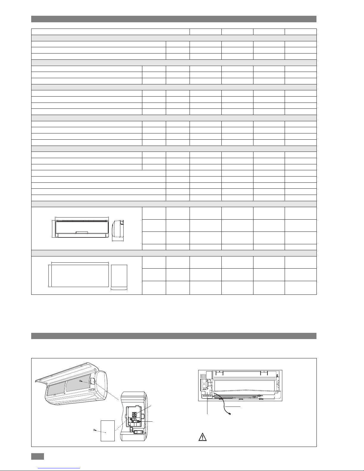
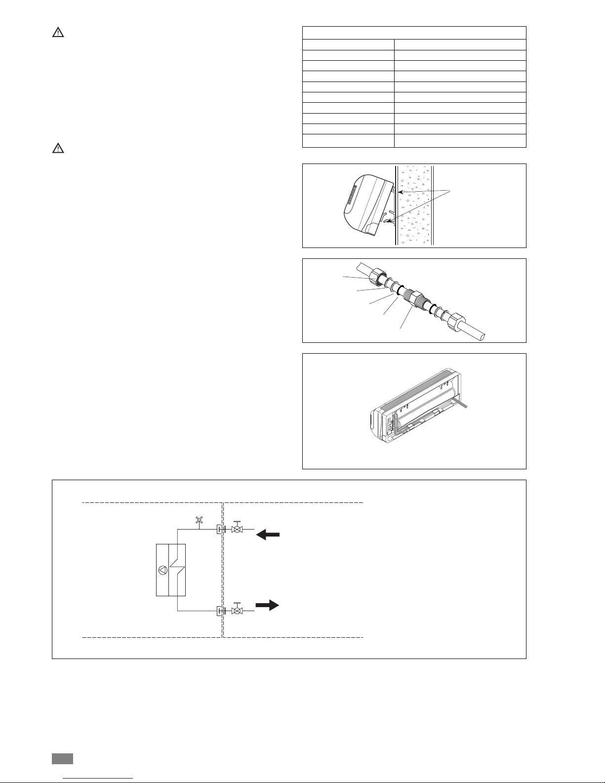
Take care when removing the protective cover
from the indicator lights.
Rear view
Electrical connection of water
valve / Remote terminal block
Electrical power
supply inlet
Terminal block
Cable gland
ELECTRICAL CONNECTIONS
ACCESS TO CONNECTIONS General

5
Water IN connection
Water OUT connection
Condensate connection
Rear view
HYDRAULIC CONNECTIONS
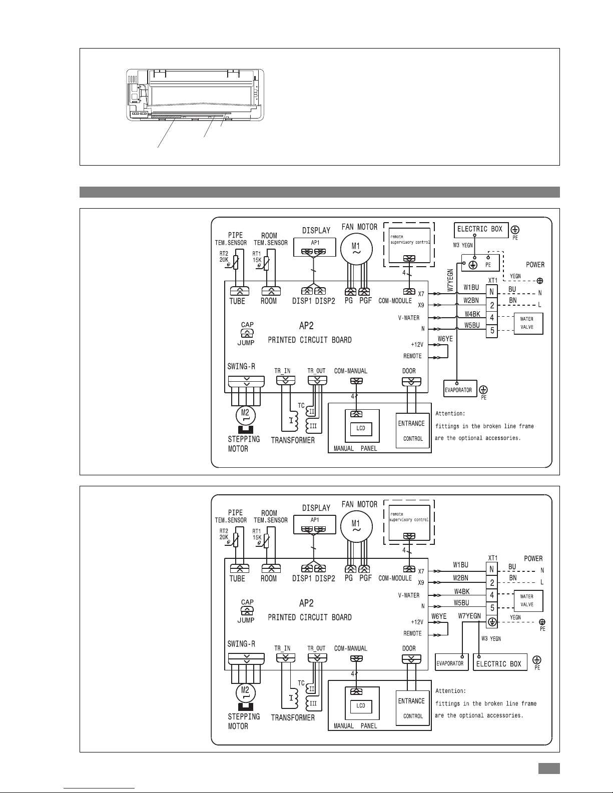
WIRING DIAGRAMS General
MHD 30-40
MHD 50-60

6
Holes for
fixing screws
Hole for electric cable
conduits and condensate
drain pipe to pass through
4,1x32
INSTALLATION Installer
LOCATING THE INDOOR UNIT
The place of installation must be established by the installation designer/services engineer or by a technically competent person and must take into account technical requirements as well as applicable current laws and regulations.
The fan coil must be installed by a qualified company in
accordance with applicable laws and regulations in force in
the country of installation.
The fan coils are designed for wall mounting.
Installation should allow the treated air to circulate freely
throughout the room and leave sufficient space for access to
the unit for maintenance or servicing operations.
Before starting installation, decide on the position of the
indoor, taking into account the minimum technical
spaces required.
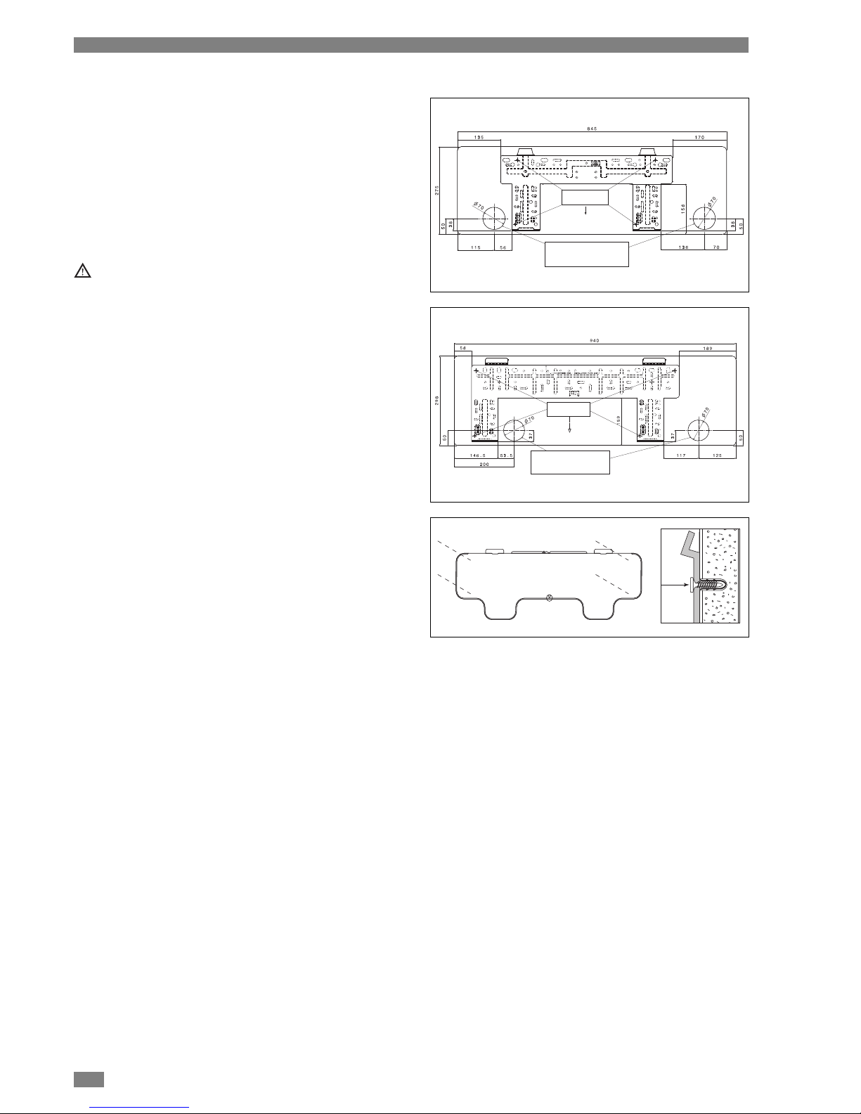
To mount the unit on the wall:
- Fix the metal plate to the wall using the provided screw
anchors and screws.
UNIT INSTALLATION
MHD 30-40
Holes for
fixing screws
Hole for electric cable
conduits and condensate
drain pipe to pass through
MHD 50-60

7
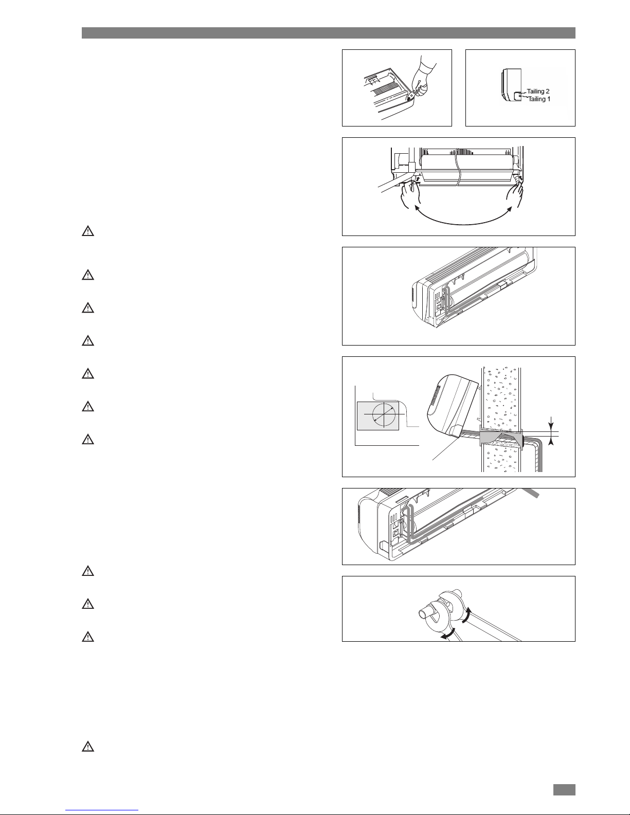
Knockouts
2~5 mm
Outdoors
Indoors
Protective pipe
A
DRAIN PIPE CONNECTION
The indoor unit is fitted with a condensate drain pipe to
which a lagged drainage hose should be connected leading
to a suitable drainage outlet. The appliance is designed for
condensate drainage from either side, although the drain
pipe is connected in the factory on the left.
- Remove front panel as described in Maintenence section.
- Using a tool remove fixing spring located in left condesate
pipe.
- Remove plug present.
- Place fixing spring in right condensate pipe.
- Replace front panel
Connect a lagged drainage pipe (inside ø 16 mm) to the
hose fitting of the drain pipe and direct it towards a suitable drainage outlet.
After installation, check that the condensation flows out
regularly.
For data regarding installation, see the section “Information for installation”.
To access the connections, see the section “Access to
connections”.
The drainage pipe must have a 3% slope downwards
towards the drain.
Check all the joints for leaks.
Apply heat-insulating material to the joints.
CONNECTION TO THE WATER SYSTEM
For connections at the sides:
- Remove the relevant knockout from the housing
For connections at the rear:
- Drill a hole Ø 60 in the wall within one of the two areas A”
(see section “Information for installation”).
Pass a protective plastic pipe through the hole in the
wall.
Ensure that the section of wall in question has no bearing structural members, pipes or electric cables.
Upon completion of work it is advisable to close the
holes made in the wall using elastic and, if possible,
soundproofing material.
- To facilitate carrying out the water connections, keep the
unit raised by means of a spacer.
- If necessary position the connections in the space provided at the rear of the indoor unit and fix them with the provided bracket A.
Position the pipes so that they occupy as little space as
possible in order to facilitate hooking of the appliance
onto the metal plate.
CONNECTIONS Installer

8
Hook on here
1
2
3
4
5
The choice and installation of the components is left to
the installer, who should operate in a workmanlike manner in compliance with current laws and regulations.
The use of water disconnectors is compulsory on systems to which anti-freeze has been added.
Special supply/fill-up water should be treated with suitable systems. Reference values may be taken as those
given in the table.
Do not apply the adhesive tape too tightly in order not to
damage the insulation.
To carry out the water connections
- Hook the fan coil to the metal plate keeping the lower
edge raised.
- Position the water pipes.
- Clean the surfaces of the fittings and the ends of the water
pipes.
- Position the supplied joints on the ends of the water pipes
and on the fan coil fittings.
- Tighten the joints properly.
- Place insulating material over the joints, fixing it with adhesive tape in order not to damage the insulation.
- Hook the fan coil onto the metal plate.
REFERENCE VALUES H2O
pH 6-8
Electric conductivity less than 200 mV/cm (25°C)
Chlorine ions less than 50 ppm
Sulphuric acid ions less than 50 ppm
Total iron less than 0.3 ppm
Alkalinity M less than 50 ppm
Total hardness less than 35 °f
Sulphur ions none
Ammonium ions none
Silicate ions less than 30 ppm
Connections carried out
in the factory
Connections carried
out by the installer
Outlet
Inlet
3
1
2
4
5
54
1 Fan
2 Heat exchanger
3 Air valve
4 Joint (supplied)
5 Ball shutoff valve

9
ELECTRICAL CONNECTIONS
The fan coil leaves the factory fully wired and only requires:
- connecting to the mains electricity supply.
For any work of an electrical nature, see the section
“Wiring diagrams”.
Check that:
- The characteristics of the mains electricity supply aresuitable for the maximum input values indicated in the
table in the section “Technical data”, also taking into
consideration any other appliances working in parallel.
- The supply voltage corresponds to the rated value +/10%.
The following is compulsory:
- Installation of an omnipolar line disconnecting switch to
CEI-EN standards (with contact separation of at least 3
mm) near the appliance.
- An efficient earth connection.
The manufacturer cannot be held liable for any damage
or injury caused by failure to earth the installation or failure to comply with the wiring diagrams.
Under no circumstances should gas or water pipes be
used for earthing the appliance.
To access the connections, see the section “Access to
connections”.
POWER SUPPLY
- Carry out the connections as shown in the figure.
The unit comes with a power cable 1.6 m long.
The unit ON-OFF switch must be in the ON (I) position”.
- Upon completion of connections, secure the cables with
cable glands and replace the terminal block covers.

10
FITTING THE FILTERS Installer
The fan coil comes with air filters designed to absorb microscopic particles of dust, pollen and mould/mildew.
To install, proceed as follows:
- Put the installation on/off switch to “off”.
Installing the air filter reduces the airflow and consequently the cooling and heating capacity. In this case it is
recommended to use the air-conditioner at MEDIUM or
HIGH speed.
Clean air filters once every 2 weeks.
Keep the air filters sealed until they are to be used.
When inserting the air filters avoid contact with the
exchanger coil or use suitable personal protective equipment.
FIRST TIME OF SWITCHING ON Installer
Before starting up the fan coil for the first time and carrying
out the functional test, it is indispensable that:
- All the safety conditions have been satisfied
- The appliance is correctly positioned
- The electrical, cooling circuit and condensate drain connections have been carried out correctly
- The shutoff valves are open.
Then:
- Put the installation on/off switch to "on"
MHD models
- Activate the fan coil using the remote control
- Check operation in the various modes
- Check the fan speeds of operation
See the instructions in the User Guide on how to use the
remote control.
AUTOMATIC RESTART
The fan coil is fitted with a device that allows automatic
restart in the event of a blackout and subsequent return of
the power supply.
The fan coil restarts in the previously set mode of operation.
ON
OFF

11
FILLING AND DRAINING THE INSTALLATION Installer
FILLING
- Before filling, put the installation on/off switch to "off”.
- Check that the drain tap is closed
- Remove unit cabinet as described in Maintenance section
- Open the air valve on the fan coil and the installation (see
figure)
- Start filling by slowly opening the installation water supply
tap outside the appliance
- When water starts to come out the air valve, close it immediately and continue filling until the pressure gauge shows
the value envisaged for the installation.
Check the air valve for leaks.
Check all the joints for leaks.
It is recommended that this operation be repeated after
the appliance has been working for several hours and
that the installation pressure be checked periodically.
This operation must be carried out by specialised technical personnel.
DRAINING
- Before draining, put the installation on/off switch to "off".
- Check that the installation supply tap is closed.
- Open the fan coil and the installation air valve.
If anti-freeze has been put into the system, it must not be
allowed to drain away freely since it is a pollutant. It must
be collected and if possible recycled.
This operation must be carried out by specialised technical personnel.
ON
OFFONOFF

12
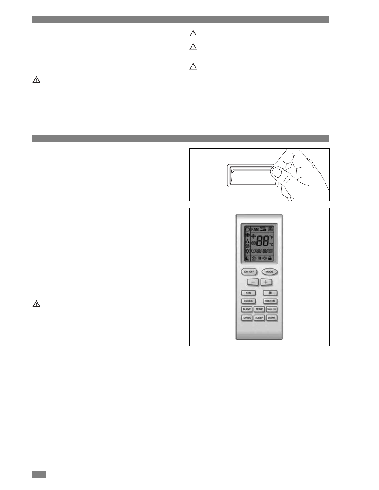
Signal transmitter
WIRELESS REMOTE CONTROL User
A. ON/OFF button
Press this button, the unit will be turned on, press it once
more, the unit will be turned off.
When turning on or turning off the unit, the Timer, Sleep
function will be canceled.
B. MODE button
Auto, Cool, Fan, Heat mode can be selected circularly.
Fan mode is default while power on. Under Fan mode,
the temperature will not be changed, it shows 24°C
(75°F). Under Heat mode, the initial value is 28°C (82°F);
Under other modes, the initial value is 25°C (77°F).
C. SLEEP button
Sleep On and Sleep Off can be selected. After powered
on , Sleep Off by default. After the unit is turned off, the
Sleep function is canceled. After Sleep function set up,
the signal of Sleep will display. In this mode, the time of
timer can be adjusted. Under Fan and Auto modes, this
function is not available.
D. FAN button
Auto, Low, Middle, High speed can be circularly selected.
After powered on, Auto fan speed is default. Under Dehumidify mode, Low fan speed only can be set up.
Under the Dry mode, the fan speed isn't adjustable.
E. CLOCK button
Press this button, the clock can be set up, signal blink
on display. Within 5 seconds, the value can be adjusted
by pressing + or - button, if continuously press this button
for 2 seconds above, in every 0.5 seconds, the value on
ten place of Minute will be increased 1. During blinking,
repress the Clock button, signal will be constantly displayed and it denotes the setting succeeded. After powered on, 12:00 is defaulted to display and signal will
be displayed. If symbol is displayed the current time
value is Clock value, otherwise is Timer value.
F. LIGHT button
Press this button to select LIGHT on or off in the displayer. When the LIGHT on is set, the icon will be displayed and the indicator light in the displayer will be
on. When the LIGHT off is set, the icon will be displayed
and the indicator light in the displayer will be off.
G. button
For presetting temperature increasing. Press this button,
can set up the temperature, when unit is on. Continuously press and hold this button for more than 2 seconds, the
corresponding contents will be changed rapidly, until
unpress the button °C (°F) laying all along. In Auto mode,
the temperature can not be set up. Centigrade setting
range: 16-30; Fahrenheit scale setting range 61-86.
Be sure that there are no obstructions between receiver and
remote controller; Don't drop or throw the remote control;
Don't let any liquid in the remote control and put the remote
control directly under the sunlight or any place where is very
hot.
Indicator symbols
AUTO
COOL
DRY
FAN
HEAT
Low FAN
Middle FAN
High FAN
Clock
Light
Sleep
Temp
Padlock
A
D
E
C
B
HG
L
M
N
F
I
AUTO
AUTO

13
H. button
To decrease set temperature. Press this button, the temperature can be set up, continuously press this button
and hold for two seconds, the relative contents can quickly change, until unhold this button and send the order that
the °C (°F) signal will be displayed all the time. The temperature adjustment is unavailable under the Auto mode.
I. TEMP button
After powered on, the setting temperature displaying is
default, (according to customers requirements to display,
if there is no requirement that will default to display the
presetting temperature and there is no icon displayed on
wireless remote control). Press this button, (When displaying ), will display presetting temperature; (when
displaying ) will display indoor ambient temperature. If
current displays indoor ambient temperature, if received
the other remote control signal, it will display presetting
temperature, 5 second later, will back to display ambient
temperature.
L. SWING UP AND DOWN button
Press this button, to set up swing angle, which circularly
changes as below:
M. TIMER ON button
Timer On setting: Signal “ON” will blink and display, signal will conceal, the numerical section will become the
timer on setting status. During 5 seconds blink, by pressing + or - button to adjust the time value of numerical section, every press of that button, the value will be
increased or decreased 1 minute. Hold pressing + or button, 2 seconds later, it quickly change, the way of
change is: During the initial 2.5 seconds, ten numbers
change in the one place of minute, then the one place is
constant, ten numbers change in the tens place of minute
at 2.5 seconds speed and carry. During 5s blink, press
the Timer button, the timer setting succeeds. The Timer
On has been set up, repress the timer On button, the
Timer.
On will be canceled. Before setting the Timer, please
adjust the Clock to the current actual time.
N. TIMER OFF button
Once press this key to enter into TIMER OFF setup, in
which case the TIMER OFF icon will blink. The method of
setting is the same as for TIMER ON.
OFF
WIRELESS REMOTE CONTROL: MODES OF OPERATION User
Selecting the mode of operation
Each time the MODE button is pressed, the mode of operation changes in the following order:
COOLING - DRY - FAN - HEATING - AUTO
The HEATING mode is not available in installations
designed for cooling only.
The fan coil is a terminal unit and its operation depends
on the boiler or cooler to which it is connected.
In the Heating mode the fan will only work when the supply water temperature is sufficiently high.
Available ranges of temperature settings:
* Only for installations that offer this mode.
Heating* 16°C ~ 30°C
Cooling 16°C ~ 30°C
Dehumidifying/dry Room temperature ± 2°C
Fan

14
SELECTING THE COOLING MODE
• Press the button to switch on the fan coil.
The symbol starts blinking on the display and a beep indicates that the fan coil has started.
• Press the MODE button repeatedly until the cooling
symbol appears on the display.
• The temperature should now be set using the ( )
keys.
• To select the fan speed, just press the FAN button repeatedly until obtaining the required fan setting (automatic,
high, medium, low).
In the cooling mode the appliance automatically takes
excess moisture from the environment.
SELECTING THE DEHUMIDIFYING/DRY MODE
It is advisable to activate this function when humidity levels
are high.
• Press the button to switch on the fan coil.
• The symbol starts blinking on the display and a beep
indicates that the fan coil has started.
• Press the MODE button repeatedly until the dehumidifying
symbol appears on the display.
• The dehumidifying level should now be set using the keys
.
• The fan speed is selected automatically by the appliance in
the dehumidifying/dry mode.
SELECTING THE FAN ONLY MODE
On sultry but not particularly hot days it could be sufficient to
activate the fan function.
• Press the button to switch on the fan coil.
• The symbol starts blinking on the display and a beep
indicates that the fan coil has started.
• Press the MODE button repeatedly until the fan symbol
appears on the display.
• Once the fan function has been activated, press the FAN
button repeatedly until obtaining the required speed (high,
medium, low).
SELECTING THE HEATING MODE
• Press the button to switch on the fan coil.
The symbol starts blinking on the display and a beep
indicates that the fan coil has started.
• Press the MODE button repeatedly until the heating
symbol appears on the display.
• Once the fan function has been activated, press the FAN
button repeatedly until obtaining the required speed (high,
medium, low).
ON/OFF
ON/OFF
ON/OFF

15
PROGRAMMING THE TIMER User
After having selected the required mode of operation, switch
on the timer by pressing the TIMER ON button when going
out in the morning so that you can find your home at a comfortable temperature when you return.
Programming switching ON
• With the fan coil switched on, press the TIMER OFF button. Time starts blinking on the display. Set hour required
of switching off using the buttons.
• Press the TIMER OFF button again to confirm the selection.
• When hour set is displayed, the appliance automatically
switches OFF.
• To delete the set time, press the TIMER button again.
There will be a beep.
Programming switching OFF
• With the fan coil switched off, press the TIMER ON button.
Time starts blinking on the display. Set hour required of
switching on using the buttons.
• Press the TIMER button again to confirm the selection.
• When hour set is displayed, the appliance automatically
switches ON.
• To delete the set time, press the TIMER button again.
There will be a beep.
SLEEP MODE User
The SLEEP mode may be set in the COOLING, HEATING
and DEHUMIDIFYING modes of operation.
This function is used to obtain a more comfortable environment while sleeping.
In the SLEEP mode:
• The appliance switches off automatically after 8 hours of
operation.
• The fan speed is automatically set on the lowest level.
• The set temperature increases by 1°C per hour if the
appliance operates in the cooling mode for 2 hours.
The temperature remains constant thereafter.
• The set temperature decreases by 1°C per hour if the
appliance operates in the heating mode for 2 hours. The
temperature remains constant thereafter.
COOLING/DEHUMIDIFYING
1 hour
START
STOP
1 hour
timer 8 hours
1° increase
1° increase
SET
TEMPERATURE

OPERATION OF WIRELESS REMOTE CONTROL User
About lock
Press + and - buttons simultaneously to lock or unlock the
keyboard. If the remote controller is locked, the icon will
be displayed on it, will flicker for three times. If the keyboard
is unlocked, the padlock will disappear.
About swing up and down
1. Press swing up and down button continuously more than
2s,the main unit will swing back and forth from up to
down, and then loosen the button, the unit will stop
swinging and present position of guide louver will be kept
immediately.
2. Under swing up and down mode, when the status is
switched from off to , if press this button again 2s later,
status will switch to off status directly; if press this button
again within 2s,the change of swing status will also
depend on the circulation sequence stated above.
About switch between Fahrenheit and Centigrade
Under status of unit off, press MODE and - buttons simultaneously to switch °C and °F.
Before using the fan coil, make checks and setting as
described below.
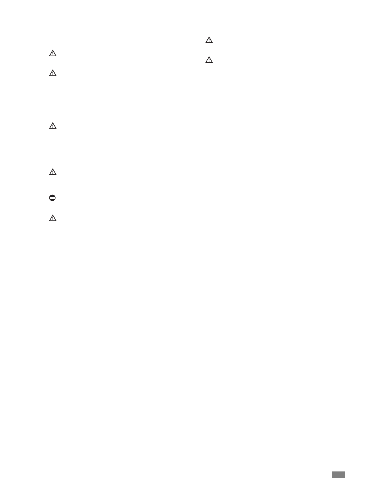
How to insert the batteries
1. Remove the battery compartment cover by sliding in the
arrow's direction;
2. Take out the old batteries;
3. Insert the new batteries (AAA 1,5V) and pay attention to
the polarity;
4. Replace the cover by sliding it into place.
NOTE:
- When changing the batteries, do not use the old or different batteries, otherwise, it can cause the malfunction of
the wireless remote control.
- If the wireless remote control will not be used for a long
time, please take them out, and don't let the leakage liquid
damage the wireless remote control.
- If the wireless remote control can not operate normally,
please take them out, after 30s later and reinsert, if they
cannot normally run, please change them.
ADJUSTING THE AIRFLOW User
Adjusting the airflow
The vertical airflow is automatically adjusted at a certain
angle after switching on the appliance according to the
mode of operation.
The airflow direction may be adjusted as required by pressing the “Swing” button on the remote control.
Up and down louver swing (variable airflow)
Press the “Swing” button once. The airflow direction louvers
automatically swing up and down.
Setting the airflow direction
Press the “Swing” button again when the louvers are in the
desired position to stop their movement.
Adjusting the horizontal airflow (manual)
- Switch off the appliance
- Turn the adjusting cursors of the horizontal airflow direction louvers by hand to change the direction as shown.
Do not turn the vertical airflow direction louvers by hand as
this could cause malfunctioning. If this occurs, switch the
appliance off and then on again with the remote control.
The louvers will automatically move to the best position.
Do not keep the vertical airflow direction louvers in a
downward position for a long time in the Cooling or
Dehumidifying modes in order to avoid dripping due to
condensation.
To adjust the vertical airflow, press
the SWING button.
Adjusting cursors of the horizontal
airflow direction louvers
Cooling Horizontal direction
Dehumidifying Horizontal direction
Heating Downwards
Fan only Downwards
16

17
EMERGENCY OPERATION User
Displayer indicator light control of the unit
It's a special selective button for the users, who are not
accustomed to the light at sleeping.
- Get the displayer indicator light on: When setting the light
function, the mark will display on the remote controller
screen by pressing this button. In which case, the displayer indicator light will be on if the AC receives this signal.
- Get the displayer indicator light off: If cancel the light function , the mark will disappear on the remote controller
screen by pressing this button. In which case, the displayer indicator light will be off if the AC receives this signal.
Emergency operation
If the wireless remote control is lost or broken, please use
the manual switch button. At this time, the unit will run at the
Fan mode, but the temperature and fan speed cannot be
changed. The operation was shown as below:
- Turn on the unit: At unit turned off, press the button , the
unit will run at Fan mode immediately. The microcomputer
will accord to the indoor temperature to select (Cooling,
Heating, Fan) and obtain the comfortable effect.
- To switch ON hi-wall unit with manual switch button,
remove cabinet of the appliance as described in maintenance section.
- Press button for at least 3 second using a tool.

18
MAINTENANCE User
Turn power off and pull out the power plug before cleaning air conditioner , or it may cause electric shock.
Never sprinkle water on the indoor unit for cleaning
because it can cause an electric shock.
Volatile liquid (e.g. thinner or gasoline) will damage the
air conditioner. Wipe the units with a dry soft cloth, or a
cloth slightly moistened with water or cleanser.
Clean the front panel
When cleaning the front panel, please dip the cloth into the
water temperature of 45°C below, then to dry the cloth and
wipe the dirty part.
Note: Please do not to immerse the front panel in water, due
to there are microcomputer components and circuit diagrams on the front panel.
Clean the air filter
Note: If dust is much more around the air conditioner, the air
filters should be cleaned many times. After taking off the filter, don't touch the fin of the unit, in order to avoid hurt your
fingers (Recommended once every three months).
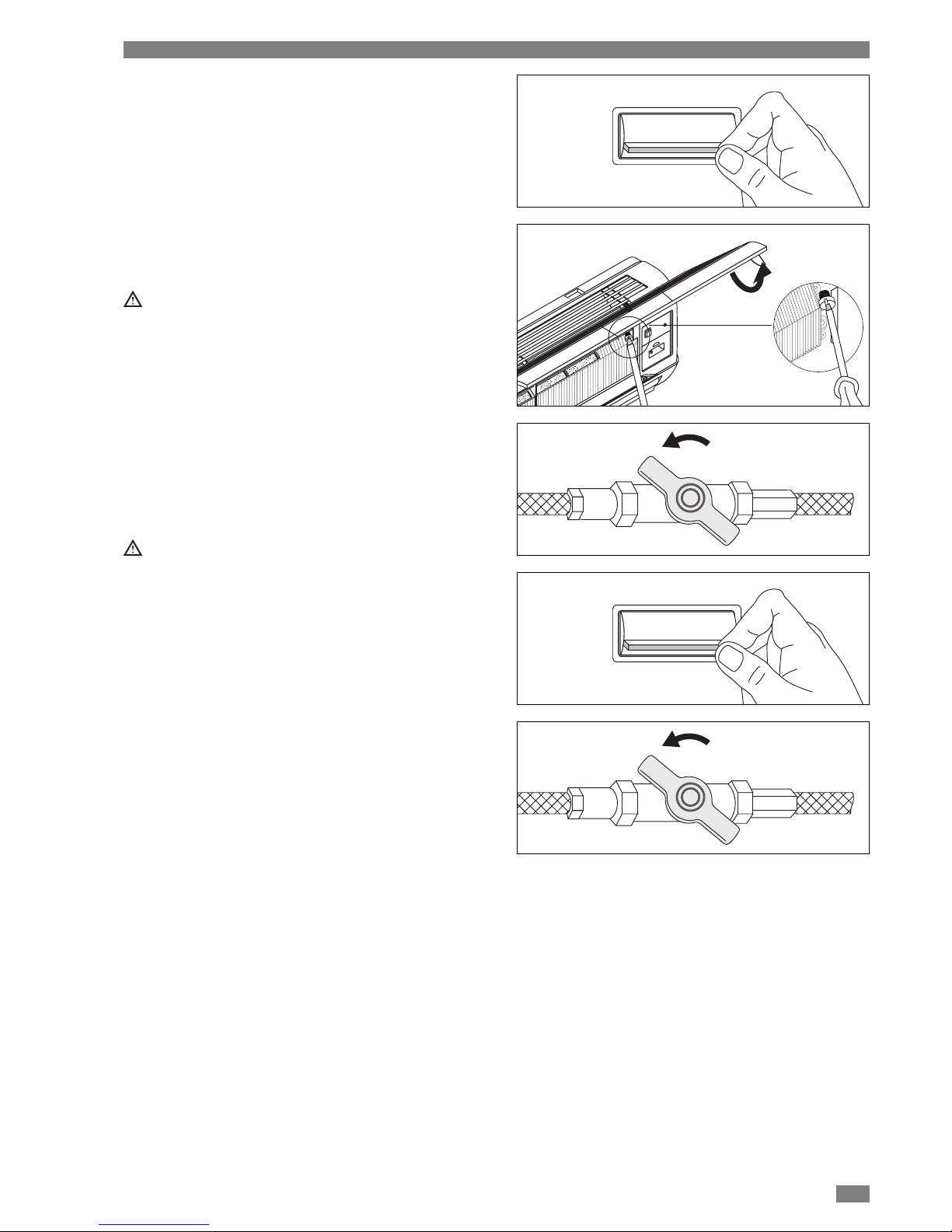
1. Take down the air filter
At the slot of surface panel to open an angle, pull the air
filter downward and take it out, please see the Fig. (a, b).
2. Clean the air filter
To clean the dust adhering to the filters, you can either
use a vacuum cleaner, or wash them with warm water the
water with the neutral detergent should below 45
degree), and dry it in the shade.
Note: Never use water above 45°C to clean, or it can
cause deformation or discoloration. Never parch it by fire,
or can cause a fire or deformation.
3. Insert the air filter
Reinsert the filters along the direction of arrowhead, and
then to close the cover and clasp it.
Check before use
- Be sure that nothing obstructs the air outlet and intake
vents.
- Check that whether ground wire is properly connected or
not.
- Check that whether the batteries of air conditioner are
changed or not.
Maintain after use
- Turn main power off.
- Clean the filter and the unit bodies.
- Adopt the special shield to cover the unit, avoid the dust
enter into the unit and get rust.

19
MAINTENANCE Service
Periodic maintenance is essential for keeping the fan coil
efficient and must be carried out at least once a year by the
After-Sales Service Centre or qualified personnel.
Before carrying out any maintenance, disconnect from
the power supply by putting the installation on/off switch
to “off”.
It may be necessary during maintenance to remove the
housing cabinets from the units; in this case proceed as follows:
- Open the motor-operated flap
- Remove all screws present and loosen the fixing screws
- Remove the housing.
Cleaning the air filters is essential for optimum operation of
the fan coil. To remove the filters:
- Switch off the appliance using the remote control.
- Put the installation on/off switch to “off”.
- Raise the front grille.
- Take out the air filters.
- Remove the dust with a vacuum cleaner.
- Replace the filters, proceeding in the reverse order.
If the filters are very dusty, wash with lukewarm water
(max 40°C) and a neutral detergent; rinse thoroughly
and leave to dry in the shade.
Clean the air filters once every 2 weeks, keeping them
sealed until they are to be used, as shown in the figure.
The appliance must not be used without the air filter.
Before carrying out any cleaning, first disconnect the
appliance from the mains electricity supply by putting the
installation on/off switch to "off".
TROUBLESHOOTING Service
TROUBLE CAUSE REMEDY
The air conditioner does not start
Inefficient
Noise and vibration
CAUSE
No electricity supply
Clogged mesh filter
Contact between metal parts
Weak outdoor unit supporting base
Loose screws
REMEDY
Check the power supply
Check fuses on control boards
Clean the filter
Check
Check
Tighten the screws

Climaveneta S.p.a.
Via Sarson 57/c
36061 Bassano del Grappa (VI)
Italy
Tel. +39 0424 509 500
Fax +39 0424 509 509
info@climaveneta.com
www.climaveneta.com
Climaveneta Home System
Via Duca d’Aosta 121
31030 Mignagola (TV)
Italy
Tel. +39 0422 4131
Fax +39 0422 413659
info.cvhs@climaveneta.com
www.climaveneta.com
Climaveneta France
3, Village d’Entreprises
ZA de la Couronne des Prés
Avenue de la Mauldre
78680 Epône
France
Tél. +33 (0)1 30 95 19 19
Fax +33 (0)1 30 95 18 18
info@climaveneta.fr
www.climaveneta.fr
Climaveneta Deutschland
Rhenus Platz 2
59439 Holzwickede
Germany
Tel. +49 2301 91222-0
Fax +49 2301 91222-99
info@climaveneta.de
www.climaveneta.de
Climaveneta
España - Top Clima
Londres 67, 1° 4°
08036 Barcelona
Spain
Tel. +34 963 195 600
Fax +34 963 615 167
topclima@topclima.com
www.climaveneta.com
Climaveneta Chat Union
Refrig. Equipment Co Ltd
88 Bai Yun Rd, Pudong Xinghuo
New dev. zone 201419 Shanghai
China
Tel. 008 621 575 055 66
Fax 008 621 575 057 97
Climaveneta Polska Sp. z o.o.
Ul. Sienkiewicza 13A,
05-120 Legionowo,
Poland
Tel. +48 22 766 34 55-57
Fax +48 22 784 39 09
info@climaveneta.pl
www.climaveneta.pl
COD. 5773038800_00
 Loading...