

Midea MHC-V16W/D2N1, MHC-V7W/D2N1, MHC-V14W/D2N1, MHC-V12W/D2RN1, MHC-V16W/D2RN1 Installation & Owner's Manual
...
INSTALLATION & OWNER’S MANUAL
MHC-V5W/D2N1
MHC-V7W/D2N1
MHC-V9W/D2N1
MHC-V10W/D2N1
MHC-V12W/D2N1
MHC-V14W/D2N1
MHC-V16W/D2N1
MHC-V12W/D2RN1
MHC-V14W/D2RN1
MHC-V16W/D2RN1
Before use, please carefully read this manual and keep it for future reference.
Thank you very much for purchasing our product.
Original instructions
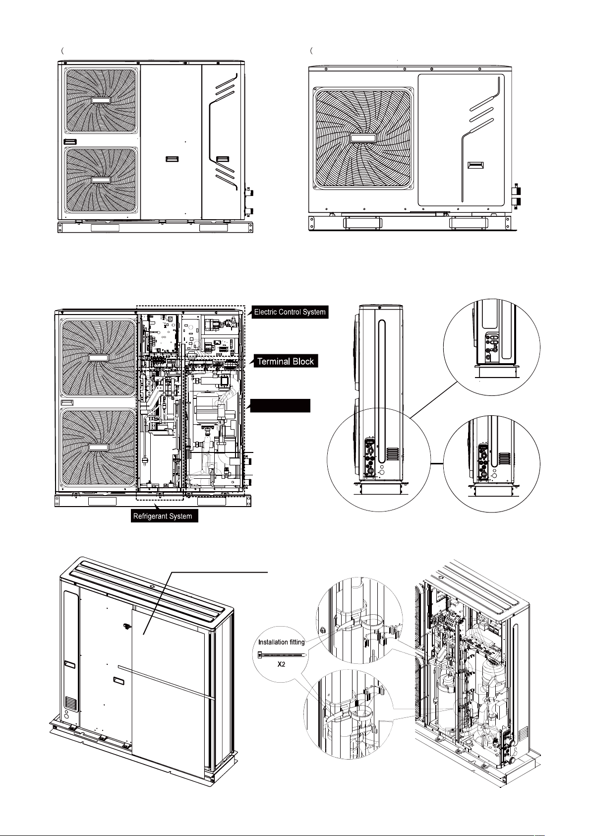
Figure 1) Figure 2)
10/12/14/16 kW
Wiring diagram:12-16kW(3-phase) for examples
Hydraulic System
5/7/9 kW
5/7/9 kW
10/12/14/16 kW
Please remove the hollow
plate after installation.
CONTENTS PAGE
1 INTRODUCTION.....................................................................1
2 ACCESSORIES......................................................................2
3 SAFETY CONSIDERATIONS.................................................2
4 BEFORE INSTALLATION......................................................3
5 IMPORTANT INFORMATION REGARDING THE
REFRIGERANT USED............................................................4
6 SELECTING INSTALLATION SITE........................................4
7 PRECAUTIONS ON INSTALLATION.....................................5
8 TYPICAL APPLICATION EXAMPLES...................................7
9 OVERVIEW OF THE UNIT.....................................................18
10 START-UP AND CONFIGURATION.....................................35
11 TEST RUN AND FINAL CHECK...........................................49
12 MAINTENANCE AND SERVICE...........................................49
13 TROUBLESHOOTING..........................................................49
14 TECHNICAL SPECIFICATIONS...........................................55
1 INTRODUCTION
1.1 General information
■ These units are used for both heating and cooling applications.
They can be combined with fan coil units, floor heating
applications, low temperature high efficiency radiators, domestic
hot water tanks (field supply) and solar kits (field supply).
■ A wired user interface is supplied with the unit to control the
installation.
■ The unit is delivered with an integrated backup heater for
additional heating capacity during cold outdoor temperatures. The
backup heater also serves as a backup in case of malfunctioning
and for freeze protection of the outside water piping during winter
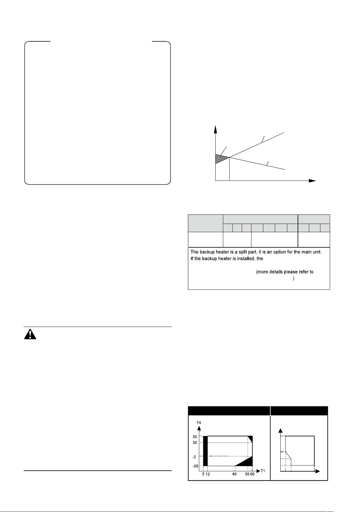
time. The capacity of backup heater for different units is listed below.
Capacity/Load
1
3
2
Outdoor temperatureTbivalent
1. Heat pump capacity
2. Required heating capacity (site dependent)
3. Additional heating capacity provided by backup heater
READ THESE INSTRUCTIONS CAREFULLY BEFORE
INSTALLATION. KEEP THIS MANUAL IN A HANDY PLACE
FOR FUTURE REFERENCE.
IMPROPER INSTALLATION OR ATTACHMENT OF
EQUIPMENT OR ACCESSORIES COULD RESULT IN
ELECTRIC SHOCKS, SHORT-CIRCUITS, LEAKS, FIRE OR
OTHER DAMAGE TO THE EQUIPMENT. BE SURE TO
ONLY USE ACCESSORIES MADE BY THE SUPPLIER
WHICH ARE SPECIFICALLY DESIGNED FOR USE WITH
THE EQUIPMENT AND HAVE INSTALLATION DONE BY A
PROFESSIONAL
ALL ACTIVITIES DESCRIBED IN THIS MANUAL SHALL BE
CARRIED OUT BY A LICENSED TECHNICIAN.
BE SURE TO WEAR ADEQUATE PERSONAL
PROTECTION SUCH AS GLOVES AND SAFETY GLASSES
WHEN PERFORMING INSTALLATION, MAINTENANCE
OR SERVICE TO THE UNIT.
IF UNSURE OF INSTALLATION PROCEDURES OR USE,
CONTACT YOUR DEALER FOR GUIDANCE
Unit
Capacity of
backup heater
3kW
(optional)*
10 12 14 16 12 14 165
9
7
3kW(standard)
4.5kW(optional)
4.5kW
port (CN6) for T1 in the main
control board of hydraulic should connect to the corresponding
port in the backup heater box 9.2.2
Function diagram of hydraulic compartment
■ Domestic hot water tank (field supply)
A domestic hot water tank can be connected to the unit(with or
without electrical booster heater is both OK).
There is a heat exchanger in the tank. If the heat exchanger
outside is enameled, the heat exchanger surface must be bigger
than 1.7m2 for matching the 10kW ~16kW unit and the heat
exchanger surface needs to be bigger than 1.4m2 for matching the
5kW~9kW unit.
■ Room thermostat (field supply)
Room thermostat can be connected to the unit(room thermostat
should be kept away from heating source when selecting the
installation place).
■ Solar kit for domestic hot water tank (field supply)
An optional solar kit can be connected to the unit.
■ Remote alarm kit (field supply)
A remote alarm kit can be connect to the unit.
■ Operation range
HEATING MODE COOLING MODE
T4
46
20
10
-5
1-phase 3-phase
5 10 25
T1
1
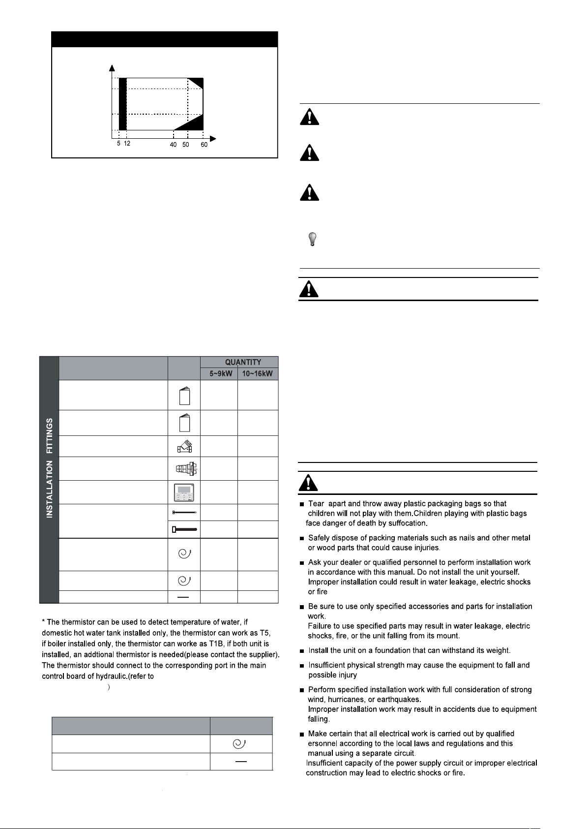
DOMESTIC WATER HEATING MODE
T4
43
30
3 SAFETY CONSIDERATIONS
The precautions listed here are divided into the following types.
They are quite important, so be sure to follow them carefully.
Meanings of DANGER, WARNING, CAUTION and NOTE symbols.
-2
-20
T4 Outdoor temperature(°C)
T1 Water flow temperature(°C)
■ No heat pump operation, backup heater or boiler only.
(*) The models have a freeze prevention function that uses the heat
pump and back up heater to keep the water system safe from
freezing in all conditions. If there is an accidental or intentional
power shutdown, using glycol is recommended (Refer to 9.3
Water pipework Caution: "Use of glycol”).
T1
1.2 Scope of this manual
This installation & owner's manual describes the procedures for
installing and connecting all monobloc outdoor unit models.
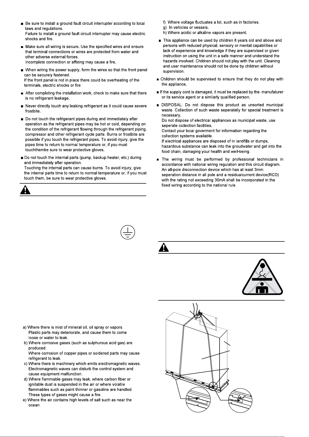
2 ACCESSORIES
2.1 Accessories supplied with the unit
NAME
Outdoor unit installation &
owner’s manual(this book)
Wire control
owner’s manual
Water outlet connection pipe
assembly
User interface kit(digital
remote controller)
Tighten belt for customer
wiring use
Thermistor for domestic hot
water tank or additional
heating source*
Thermistor for backup heater
T1
Transit line
SHAPE
1
1 1
2
1
0
3
1 1
1 0
1 1
DANGER
Indicates an imminently hazardous situation which if not
avoided, will result in death or serious injury.
WARNING
Indicates a potentially hazardous situation which if not
avoided, could result in death or serious injury.
CAUTION
Indicates a potentially hazardous situation which, if not
avoided, may result in minor or moderate injury. It is also
used to alert against unsafe practices.
NOTE
Indicates situations that could only result in accidental
equipment or property damage.
DANGER
■ Before touching electric terminal parts, turn off power switch.
■ When service panels are removed, live parts can be easily
touched by accident.
Never leave the unit unattended during installation or servicing
when the service panel is removed.
■ Do not touch water pipes during and immediately after operation
as the pipes may be hot and could burn your hand. To avoid injury,
1
11retlif epahs-Y
1
1
2
3
give the piping time to return to normal temperature or be sure to
wear protective gloves.
■ Do not touch any switch with wet fingers. Touching a switch with
wet fingers can cause electrical shock.
■ Before touching electrical parts, turn off all applicable power to
the unit.
WARNING
9.2.3 Main control board of
hydraulic module .
2.2 Accessories avaliable from supplier
water temperature thermistor
Transit line(for T1B)
SHAPENAME
2
CAUTION
■ Ground the unit.
Grounding resistance should be according to local laws and
regulations
Do not connect the ground wire to gas or water pipes,
lightning conductors or telephone ground wires.
Incomplete grounding may cause electric shocks.
a) Gas pipes.
Fire or an explosion might occur if the gas leaks.
b) Water pipes.
Hard vinyl tubes are not effective grounds.
c) Lightning conductors or telephone ground wires.
Electrical threshold may rise abnormally if struck by a lightning bolt.
■ Install the power wire at least 3 feet (1 meter) away from
televisions or radios to prevent interference or noise. (Depending
on the radio waves, a distance of 3 feet (1 meter) may not be
sufficient to eliminate the noise.)
■ Do not wash the unit. This may cause electric shocks or fire. The
appliance must be installed in accordance with national wiring
regulations. If the supply cord is damaged, it must be replaced by
the manufacturer, its service agent or similarly qualified persons in
order to avoid a hazard.
■ Do not install the unit in the following places:
4 BEFORE INSTALLATION
Before installation
Be sure to confirm the model name and the serial number of the unit.
Handling
Due to relatively large dimensions and heavy weight, the unit should
only be handled using lifting tools with slings. The slings can be fitted
into foreseen sleeves at the base frame that are made specifically for
this purpose
CAUTION
■ To avoid injury, do not touch the
air inlet or aluminum fins of the unit.
■ Do not use the grips in the fan
grills to avoid damage.
■ The unit is top heavy! Prevent the
unit from falling due to improper
inclination during handling.
Rope
≥1000mm
the hook and barycenter of the unit
should be on a line in vertical direction
to prevent improper inclination
Make the rope go through the
lifting holes from both the right
and left sides in the wooden
collet
3
The position of barycenter for different unit can be seen in the
picture below.
5/7/9 kW
atmosphere.
- Places where servicing space can be well ensured.
- Places where the units' piping and wiring lengths come within the
allowable ranges.
- Places where water leaking from the unit cannot cause damage
to the location (e.g. in case of a blocked drain pipe).
- Places where rain can be avoided as much as possible.
- Do not install the unit in places often used as a work space.
In case of construction work (e.g. grinding etc.) where a lot of dust
is created, the unit must be covered.
- Do not place any objects or equipment on top of the unit (top
plate)
- Do not climb, sit or stand on top of the unit.
- Be sure that sufficient precautions are taken in case of refrigerant
leakage according to relevant local laws and regulations.
2 When installing the unit in a place exposed to strong wind, pay
special attention to the following.
Strong winds of 5 m/sec or more blowing against the unit's air
outlet causes a short circuit (suction of discharge air), and this
may have the following consequences:
- Deterioration of the operational capacity.
- Frequent frost acceleration in heating operation.
- Disruption of operation due to rise of high pressure.
- When a strong wind blows continuously on the front of the unit,
the fan can start rotating very fast until it breaks.
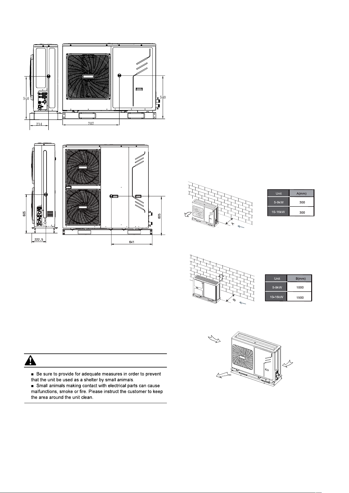
In normal condition,refer to the figures below for installation of the
unit:
10-16 kW
5 IMPORTANT INFORMATION REGARDING
REFRIGERANT USED
This product contains fluorinated greenhouse gases covered by the
Kyoto Protocol. Do not vent gases into the atmosphere.
Refrigerant type: R410A
(1)
GWP
value: 2088
(1)
GWP = global warming potential
The refrigerant quantity is indicated on the unit name plate
6 SELECTING THE INSTALLATION SITE
WARNING
1 Select an installation site where the following conditions
are satisfied and one that meets with your customer's approval.
- Places that are well-ventilated.
- Places where the unit does not disturb next-door neighbors.
- Safe places which can bear the unit's weight and vibration
and where the unit can be installed at an even level.
- Places where there is no possibility of flammable gas or product
leak.
- The equipment is not intended for use in a potentially explosive
In case of strong wind and the wind direction can be foreseen,refer
to the figures below for installation of the unit(any one is OK):
■ Turn the air outlet side toward the building's wall, fence or screen.
Make sure there is enough room to do the installation
■ Set the outlet side at a right angle to the direction of the wind.
Strong wind
Strong wind
Blown air
3 Prepare a water drainage channel around the foundation, to drain
waste water from around the unit.
4 If water does not easily drain from the unit, mount the unit on a
foundation of concrete blocks, etc. (the height of the foundation
should be about 100 mm (3.93 in).
5 If you install the unit on a frame, please install a waterproof plate
(about 100 mm) on the underside of the unit to prevent water from
coming in from the low side.
6 When installing the unit in a place frequently exposed to snow,
pay special attention to elevate the foundation as high as possible.
.
4
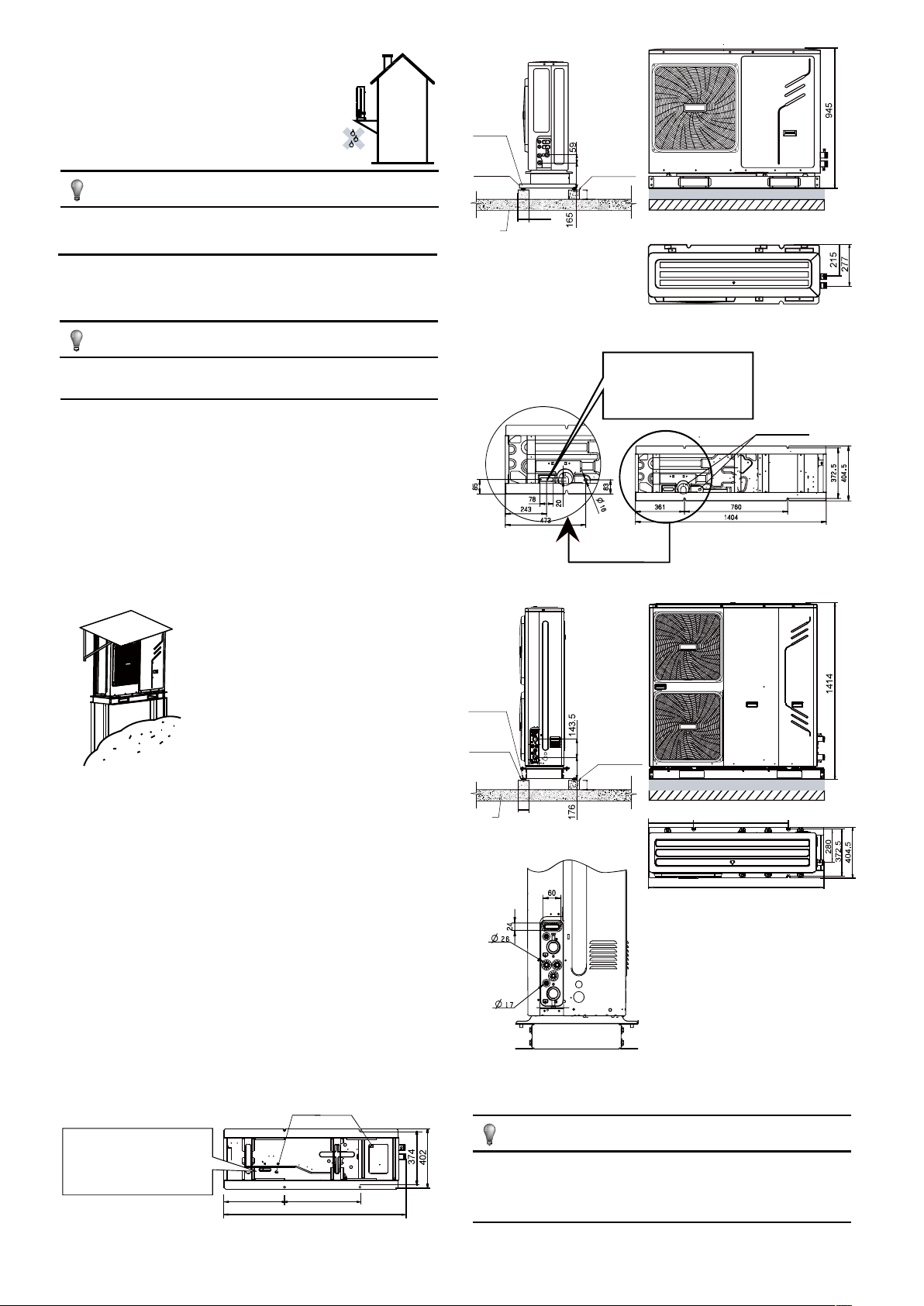
7 If you install the unit on a building frame, please
install a waterproof plate (field supply) (about 100
mm, on the underside of the unit) in order to avoid
drain water dripping. (See the picture in the right).
NOTE
Φ10
Expansion
bolt
Rubber
shocking
proof mat
Concrete
basement
h≥100mm
≥100mm
Unit is top heavy!
Try not to install on the building frame.
6.1 Selecting a location in cold climates
Refer to "Handling" in section “4 Before installation”
NOTE
When operating the unit in cold climates, be sure to
follow the instructions described below.
■ To prevent exposure to wind, install the unit with its suction side
facing the wall.
■ Never install the unit at a site where the suction side may be
exposed directly to wind.
■ To prevent exposure to wind, install a baffle plate on the air
discharge side of the unit.
■ In heavy snowfall areas it is very important to select an installation
site where the snow will not affect the unit. If lateral snowfall is
possible, make sure that the heat exchanger coil is not affected by
the snow (if necessary construct a lateral canopy).
1 Construct a large canopy.
2 Construct a pedestal.
Install the unit high enough off the ground
to prevent it from being buried in snow.
Solid
ground
or roofing
Φ10
Expansion
bolt
Rubber
shocking
proof mat
≥80mm
5/7/9 kW (unit: mm)
The drain hole is covered by
rubber plug,if one drain hole
is not enough, the big drain
hole can be opened in field.
Concrete
basement
h≥100mm
Drain hole
6.2 Selecting a location in hot climates
As the outdoor temperature is measured via the outdoor unit air
thermistor, make sure to install the outdoor unit in the shade, or
a canopy should be constructed to avoild direct sunlight. so that
it is not influenced by the sun’s heat, otherwise protection may be
possible to the unit.
7 PRECAUTIONS ON INSTALLATION
■ Check the strength and level of the installation ground so that the
unit will not cause any operating vibration or noise after installation.
■ In accordance with the foundation drawing in the figure, fix the unit
securely by means of the foundation bolts. (Prepare four sets each of
Φ10 Expansion bolts, nuts and washers which are readily available on
the market.)
■ It is best to screw in the foundation bolts until their length is
20 mm from the foundation surface.
drain hole
The drain hole is covered by
rubber plug,if one drain hole
is not enough, the big drain
hole can be opened in field.
404 502
1210
≥100mm
Solid
ground
or roofing
≥80mm
760361
1404
10/12/14/16 kW (unit: mm)
NOTE
If drain holes in the unit are covered by a mounting base or
by floor surface, raise the unit in order to provide a free space
of more than 100 mm under the unit.
5
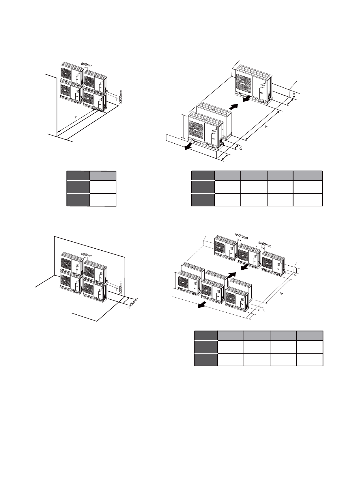
7.1 Installation servicing space
(A) In case of stacked installation
1. In case obstacles exist in front of the outlet side.
Unit A(mm)
5-9kW
10-16kW
1000
1500
(B) In case of multiple-row installation (for roof top use, etc.)
1. In case of installing one unit per row.
H
B1
Unit A(mm)
5-9kW
10-16kW
1500 500 150
2000 1000 150
B1(mm) B2(mm)
<1/2 H
B2
C(mm)
300
300
2. In case obstacles exist in front of the air inlet.
2. In case of installing multiple units (2 units or more) in lateral
connection per row.
H
B1
Unit A(mm)
5-9kW
10-16kW
2000 500 300 300
2500 1000 300 300
B1(mm) B2(mm) C(mm)
<1/2 H
B2
6
8 TYPICAL APPLICATION EXAMPLES
The application examples given below are for illustration purposes only.
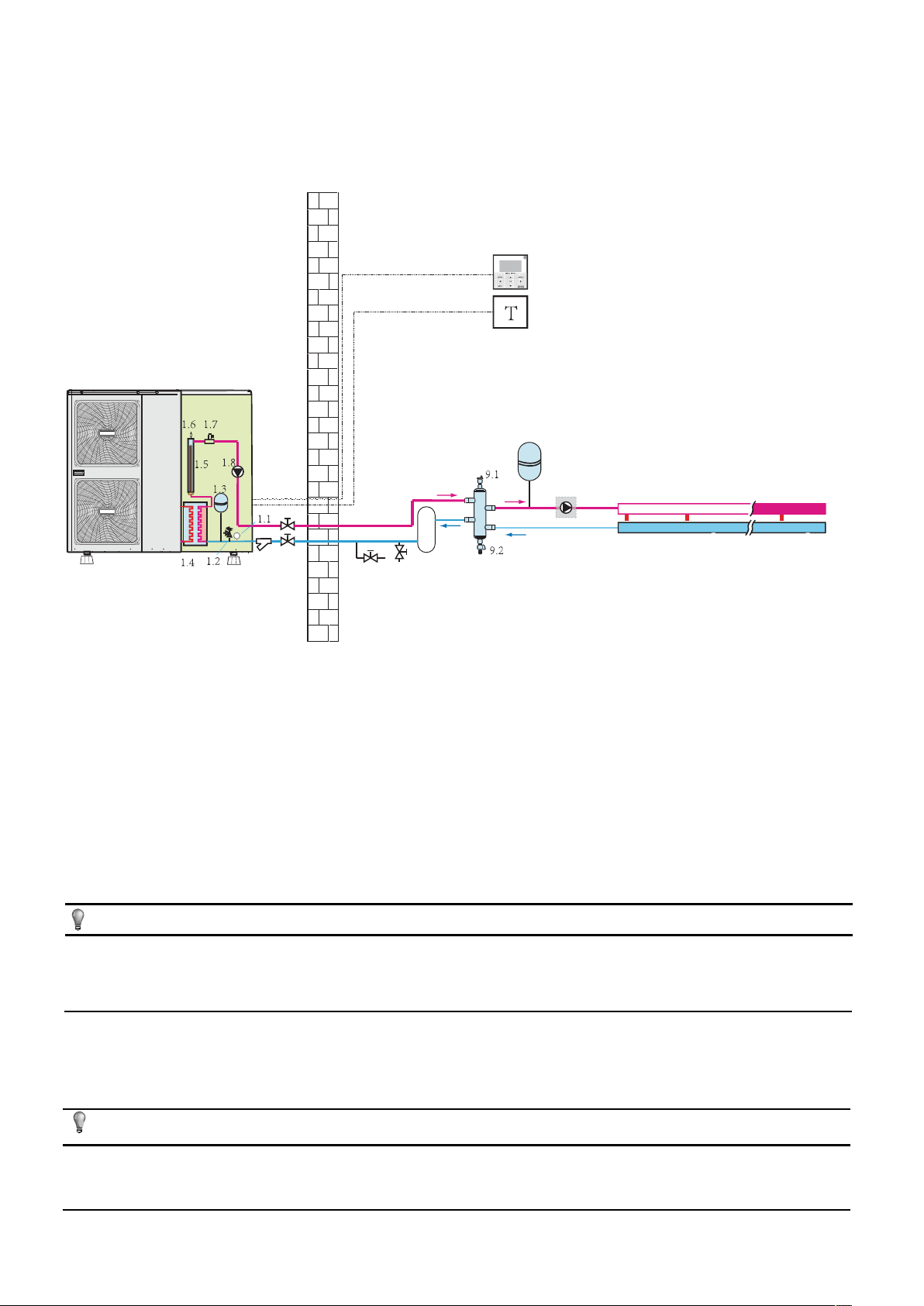
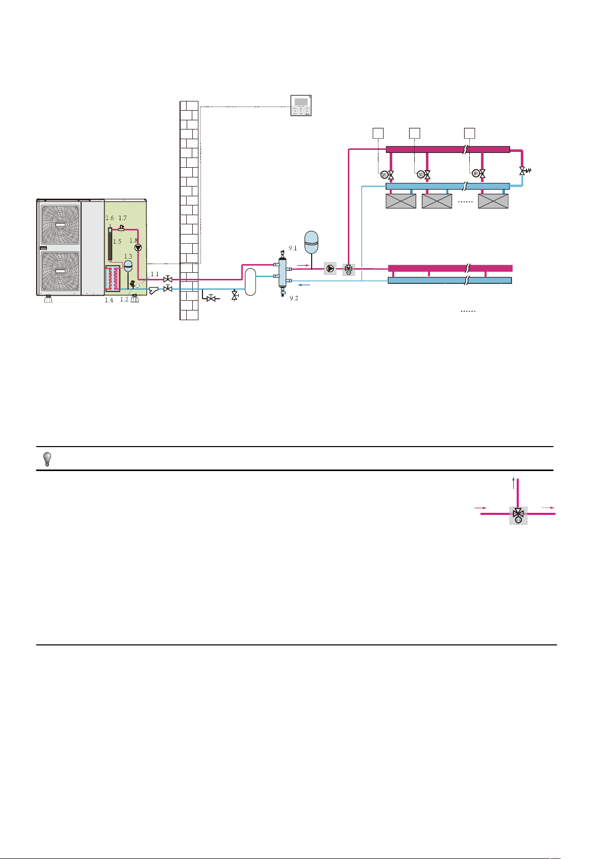
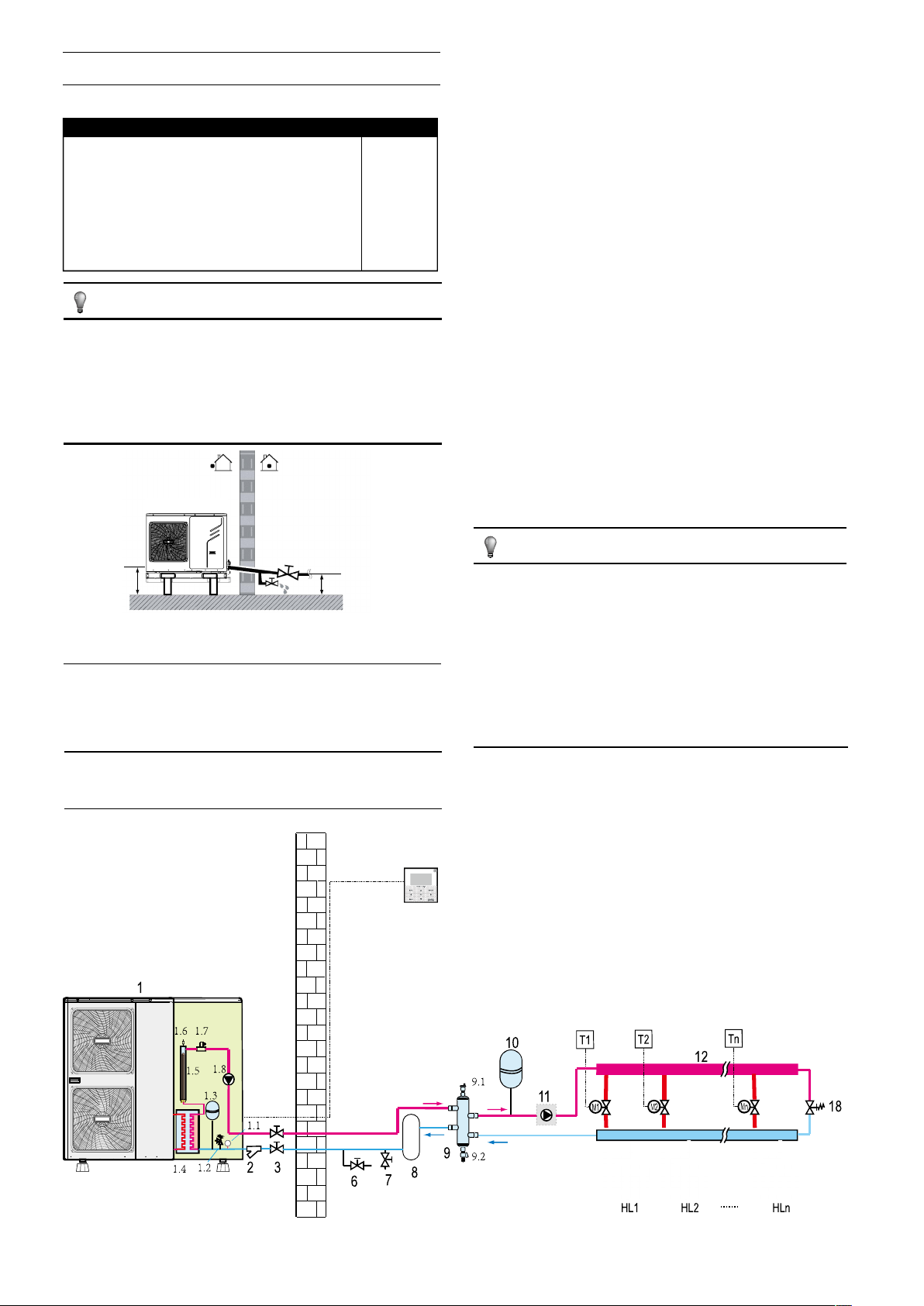
8.1 Application 1
Space heating only application with a room thermostat connected to the unit.
1
4
5
10
32
1 outdoor unit
1.1 manometer
1.2 pressure relief valve
1.3 expansion vessel
1.4 plate heat exchanger
1.5 backup heater
1.6 air purge valve
1.7 flow switch
1.8 P_i: Inside circulation pump
2 y-shape filter
3 stop valve (field supply)
4 user interface
11
12
9
8
7
6
FHL1 FHL2 FHLn
5 room thermostat (field supply)
6 drain valve (field supply)
7 fill valve (field supply)
8 buffer tank (field supply)
9 balance tank (field supply)
9.1 air purge valve
9.2 drain valve
10 expansion vessel (field supply)
11 P_o: Outside circulation pump (field supply)
12 collector (field supply)
FHL 1…n floor heating loop
.......
.......
NOTE
If the volume of balance tank(9) is larger than 30L, the buffer tank(8) is unnecessary, otherwise the buffer tank(8) should be installed and
the total volume of balance tank and buffer tank should larger than 30L. The drain valve (6) should be installed at the lowest positon of
the system. For 5/7/9kW unit, the backup heater (1.5) is not integrated in the outdoor unit. An independent backup heater can be selected
and installed in the door.
Unit operation and space heating
When a room thermostat is connected to the unit and when there is a heating request from the room thermostat, the unit will start operating
to achieve the target water flow temperature as set on the user interface. When the room temperature is above the thermostat set point in the
heating mode, the unit will stop operating. The circulation pump (1.8) and (11) will also stop running. The room thermostat is used as a switch
here.
NOTE
Make sure to connect the thermostat wires to the correct terminals, method B should be selected (see "For room thermostat" in 9.6.6
connection for other components). To correctly configure the ROOM THERMOSTAT in the FOR SERVICEMAN mode see 10.7 Field
settings/ROOM THERMOSTAT.
7
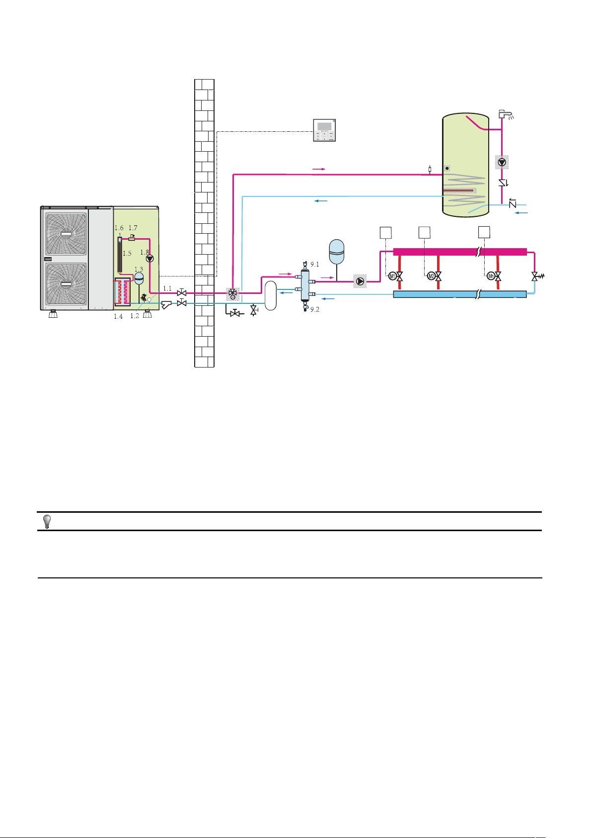
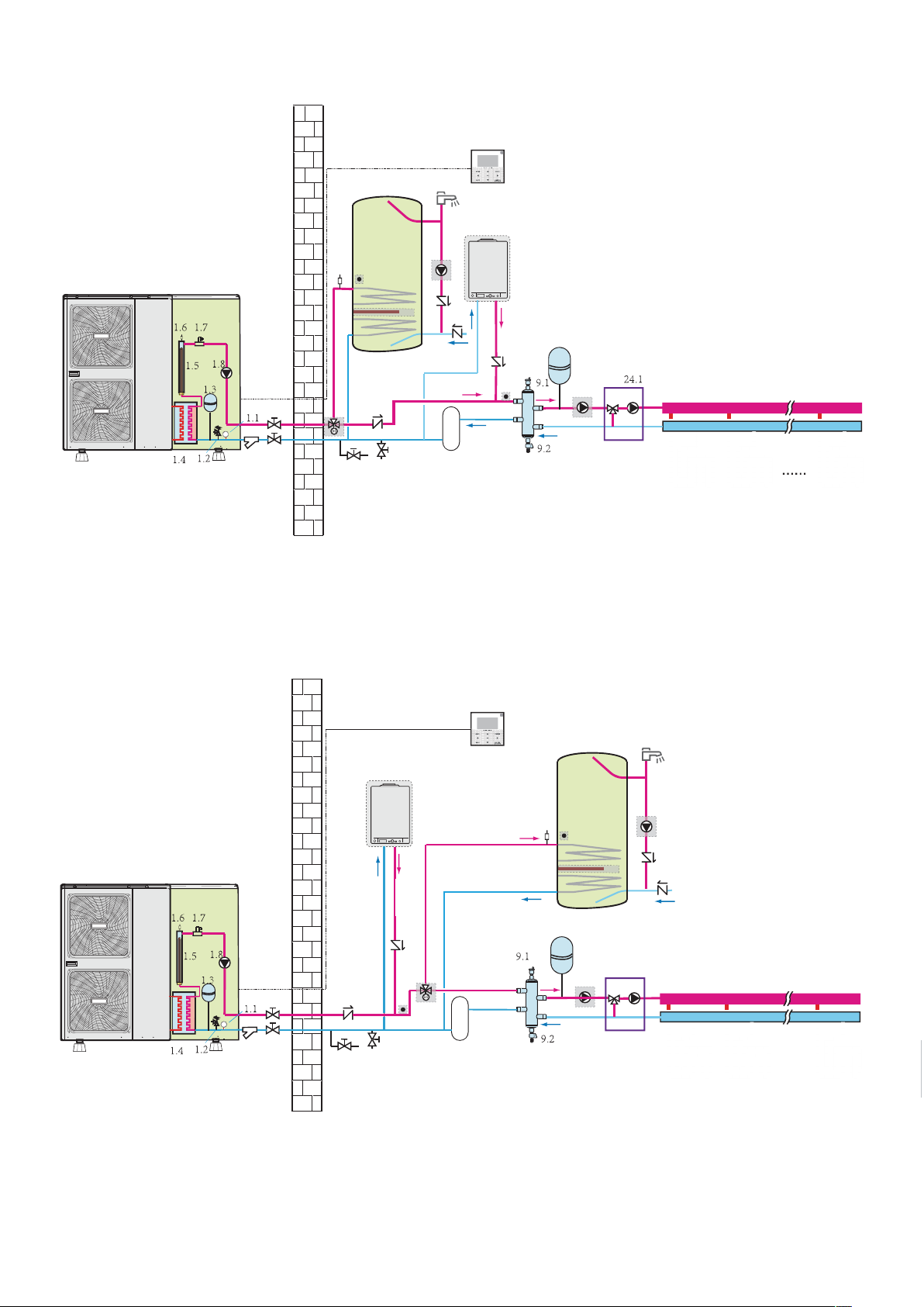
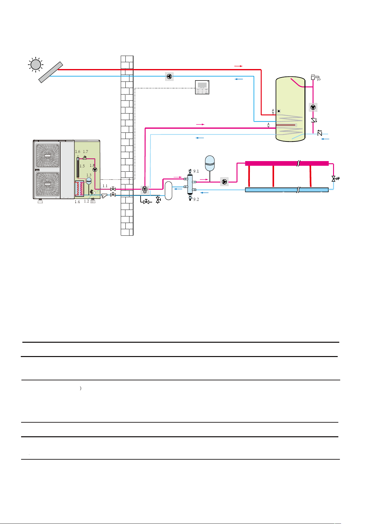
8.2 Application 2
Space heating only application without room thermostat connected to the unit. The temperature in each room is controlled by a valve on each water
circuit. Domestic hot water is provided through the domestic hot water tank that is connected to the unit.
1
1 outdoor unit
1.1 manometer
1.2 pressure relief valve
1.3 expansion vessel
1.4 plate heat exchanger
1.5 backup heater
1.6 air purge valve
1.7 flow switch
1.8 P_i: circulation pump inside the unit
2 y-shape filter
3 stop valve (field supply)
19
9
32
6
4 user interface
6 drain valve (field supply)
7 fill valve (field supply)
8 buffer tank (field supply)
9 balance tank (field supply)
9.1 air purge valve
9.2 drain valve
10 expansion vessel (field supply)
11 P_o: outside circulation pump (field supply)
12 collector (field supply)
13 domestic hot water tank (field supply)
8
7
10
13
15
4
13.3
14
13.1
13.2
T1
T2
16
17
17
Tn
12
11
18
FHL1 FHL2 FHLn
13.1 booster heater
13.2 heat exchanger coil
13.3 air purge valve
14 T5: temperature sensor
15 hot water tap (field supply)
16 P_d: DHW pump (field supply)
17 non-return valve (field supply)
18 bypass valve (field supply)
19 SV1: 3-way valve (field supply)
FHL 1...n floor heating loop
M1...n motorized valve (field supply)
T1…n room thermostat (field supply)
NOTE
If the volume of balance tank(9) is larger than 30L, the buffer tank(8) is unnecessary, otherwise the buffer tank(8) should be installed and
the total volume of balance tank and buffer tank should larger than 30L. The drain valve (6) should be installed at the lowest positon of
the system. For 5/7/9kW unit, the backup heater (1.5) is not integrated in the outdoor unit. An independent backup heater can be selected
and installed in the door.
■ Circulation pump operation
With no room thermostat connected to the unit (1) the circulation pump (1.8) and (11) will operate as long as the unit is on for space heating.
The circulation pump (1.8) will operate as long as the unit is on for heating domestic hot water (DHW).
■ Space heating
1) The unit (1) will operate to achieve the target water flow temperature set on the user interface.
2) When the circulation in each space heating loop (FCU1...n) is controlled by remote controlled valves (M1...n), it is important to provide a
bypass valve (18) to ensure that the flow switch safety device is not activated.
The bypass valve should be selected so that at all times the minimum water flow as mentioned in 9.3 Water pipework is guaranteed.
■ Domestic water heating
1) When the domestic water heating mode is enabled (either manually by the user, or automatically through scheduling) the target domestic
hot water temperature will be achieved by a combination of the heat exchanger coil and the electrical booster heater (when the booster heater
in the tank is set to YES).
2) When the domestic hot water temperature is below the user configured set point, the 3-way valve will be activated to heat the domestic
water by means of the heat pump. If there is a huge demand for hot water or a high hot water temperature setting, the booster heater (13.1)
can provide auxiliary heating.
8
CAUTION
Make sure to fit the 3-way valve correctly. For more details, refer to 9.6.6 Connection for other components/For 3-way valve SV1.
NOTE
The unit can be configured so that at low outdoor temperatures, water is exclusively heated by the booster heater. This assures
that the full capacity of the heat pump is available for space heating.
Details on domestic hot water tank configuration for low outdoor temperatures (T4DHWMIN) can be found in 10.7 Field settings/How to
set the DHW MODE.
8.3 Application 3
Space cooling and heating application with a room thermostat suitable for heating/cooling changeover when connected to the unit. Heating is
provided through floor heating loops and fan coil units. Cooling is provided through the fan coil units only. Domestic hot water is provided
through the domestic hot water tank which is connected to the unit.
4
5
13
15
1
32
1 outdoor unit
1.1 manometer
1.2 pressure relief valve
1.3 expansion vessel
1.4 plate heat exchanger
1.5 backup heater
1.6 air purge valve
1.7 flow switch
1.8 P_i: circulation pump inside the unit
2 y-shape filter
3 stop valve (field supply)
4 user interface
5 room thermostat (field supply)
6 drain valve (field supply)
7 fill valve (field supply)
8 buffer tank (field supply)
9 balance tank (field supply)
19
12
13.3
14
13.1
13.2
17
17
16
FCUnFCU2FCU1
10
20
11
12
9
8
7
6
FHL1 FHL2 FHLn
9.1 air purge valve
9.2 drain valve
10 expansion vessel (field supply)
11 P_o: outside circulate pump (field supply)
12 collector (field supply)
13 domestic hot water tank (field supply)
13.1 booster heater
13.2 heat exchanger coil
13.3 air purge valve
14 T5:temperature sensor
15 hot water tap (field supply)
16 P_d: DHW pipe pump (field supply)
17 non-return valve (field supply)
19 SV1: 3-way valve (field supply)
20 SV2: 2-way valve (field supply)
FHL 1...n floor heating loop
FCU 1...n fan coil units
NOTE
If the volume of balance tank(9) is larger than 30L, the buffer tank(8) is unnecessary, otherwise the buffer tank(8) should be installed and the total
volume of balance tank and buffer tank should larger than 30L. The drain valve(6) should be installed at the lowest positon of the system.
9
■Pump operation and space heating and cooling
According to the season, the unit will switch to either heating or cooling mode according to the temperature detected by the room thermostat.
When space heating/cooling is requested by the room thermostat (5), the pump will start operating and the unit (1) will switch to heating mode/cooling
mode. The unit (1) will operating to achieve the target cold/hot water leaving temperature.
In the cooling mode. the motorized 2-way valve (20) will close to prevent cold water running through the floor heating loops (FHL).
3
CAUTION
■ Make sure to connect the thermostat wires are routed to the correct terminals and to configure the ROOM THERMOSTAT in the user interface
correctly (see 10.7 Field settings/ROOM THERMOSTAT). Wiring of the room thermostat should follow method A as described in 9.6.6
connection for other components/For room thermostat.
■ Wiring of the 2-way valve (20) is different for a NC (normal closed) valve and a NO (normal open) valve! Make sure to connect to the
correct terminal numbers as detailed on the wiring diagram.
The ON/OFF setting of the heating/cooling operation cannot be done on the user interface.
■ Domestic water heating
Domestic water heating is as described in 8.2 Application 2.
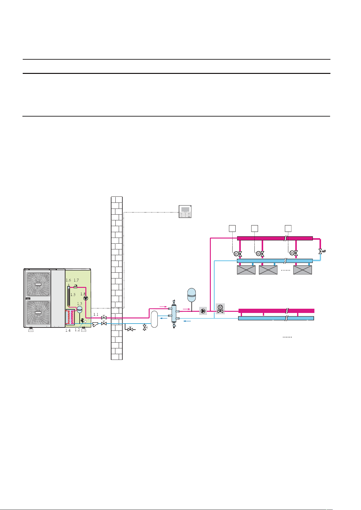
8.4 Application 4
Space cooling and heating application without a room thermostat connected to the unit, but with heating/cooling thermostat controlling the fan
coil units. Heating is provided through floor heating loops and fan coil units. Cooling is provided through the fan coil units only.
1
32
1 outdoor unit
1.1 manometer
1.2 pressure relief valve
1.3 expansion vessel
1.4 plate heat exchanger
1.5 backup heater
1.6 air purge valve
1.7 flow switch
1.8 P_i: circulation pump in the unit
2 y-shape filter
4
10
9.1
11
9
8
7
6
3 stop valve (field supply)
4 user interface
6 drain valve (field supply)
7 fill valve (field supply)
8 buffer tank (field supply)
9 balance tank (field supply)
9.1 air purge valve
9.2 drain valve
10 expansion vessel (field supply)
11 P_o: outside circulate pump (field supply)
9.2
20
12 collector (field supply)
18 bypass valve (field supply)
20 SV2: 2-way valve (field supply)
FHL 1...n floor heating loop
FCU 1...n fan coil units
M1...n motorized valve (field supply)
T1…n room thermostat (field supply)
T2 TnT1
12
FCUnFCU2FCU1
12
FHL1 FHL2 FHLn
18
10
NOTE
If the volume of balance tank(9) is larger than 30L, the buffer tank(8) is unnecessary, otherwise the buffer tank(8) should be installed and the
total volume of balance tank and buffer tank should larger than 30L.The drain valve (6) should be installed at the lowest positon of the system.
For 5/7/9kW unit, the backup heater (1.5) is not integrated in the outdoor unit. An independent backup heater can be selected and installed in the
door.
Pump operation
With no room thermostat connected to the unit (1), the circulation pump (1.8) and (11) will operate as long as the unit is on for space heating.
The pump (1.8) will operate as long as the unit is on for heating domestic hot water.
NOTE
Details on pump configuration can be found in 10.5 setting the pump speed.
Space heating and cooling
According to the season, the customer selects cooling or heating through the user interface. The unit (1) will operate in cooling mode or heating
mode to achieve the target water flow temperature. In heating mode, the 2-way valve (20) is open. Hot water is provided to both the fan coil units
and the floor heating loops. In cooling mode, the motorized 2-way valve (20) is closed to prevent cold water running through the floor heating loops
(FHL).
CAUTION
When closing several loops in the system by remotely controlled valves, it might be required to install a bypass valve (18) to avoid the
flow switch safety device from being activated. See also 8.2 Application 2.
Wiring of the 2-way valve (20) is different for a NC (normal closed) valve and a NO (normal open) valve. The NO valve is unavailable
to this unit. Make sure to connect to the correct terminal numbers as detailed on the wiring diagram.
The ON/OFF setting of the heating/cooling operation is done by the user interface.
8.5 Application 5
Space heating with an auxiliary boiler (alternating operation).
Space heating application by either the unit or by an auxiliary boiler connected in the system.
■ The unit controlled contact (also called 'permission signal for the auxiliary boiler") is determined by the outdoor temperature (thermistor
located at the outdoor unit). See 10.7 Field settings/OTHER HEATING SOURCE
■ Bivalent operation is possible for both space heating operation and domestic water heating operation.
■ If the auxiliary boiler only provides heat for space heating, the boiler must be integrated in the piping work and in the field wiring according to
the illustration for application a.
■ If the auxiliary boiler is also providing heat for domestic hot water, the boiler can be integrated in the piping work and in the field wiring
according to the illustration for application b.
■ Application c can be used If the temperature of water from the outdoor unit is not high enough. An additional 3-way valve should be
installed, if ambient temperature is high and thus water from outdoor unit is high enough, The boiler will not work and water will not flow past
the boiler. When ambient temperature is low and and thus water from outdoor unit is not high enough, the boiler will work and the 3-way valve
will open to make water from outdoor unit flow past the boiler and be heated again.
CAUTION
Be sure that the boiler and the integration of the boiler in the system is in accordance with relevant local laws and regulations.
11
Application a
Boiler provide heat for space heating only
1
13.3
14
13.2
13
13.1
4
15
AHS
16
17
17
10
17
17
19
32
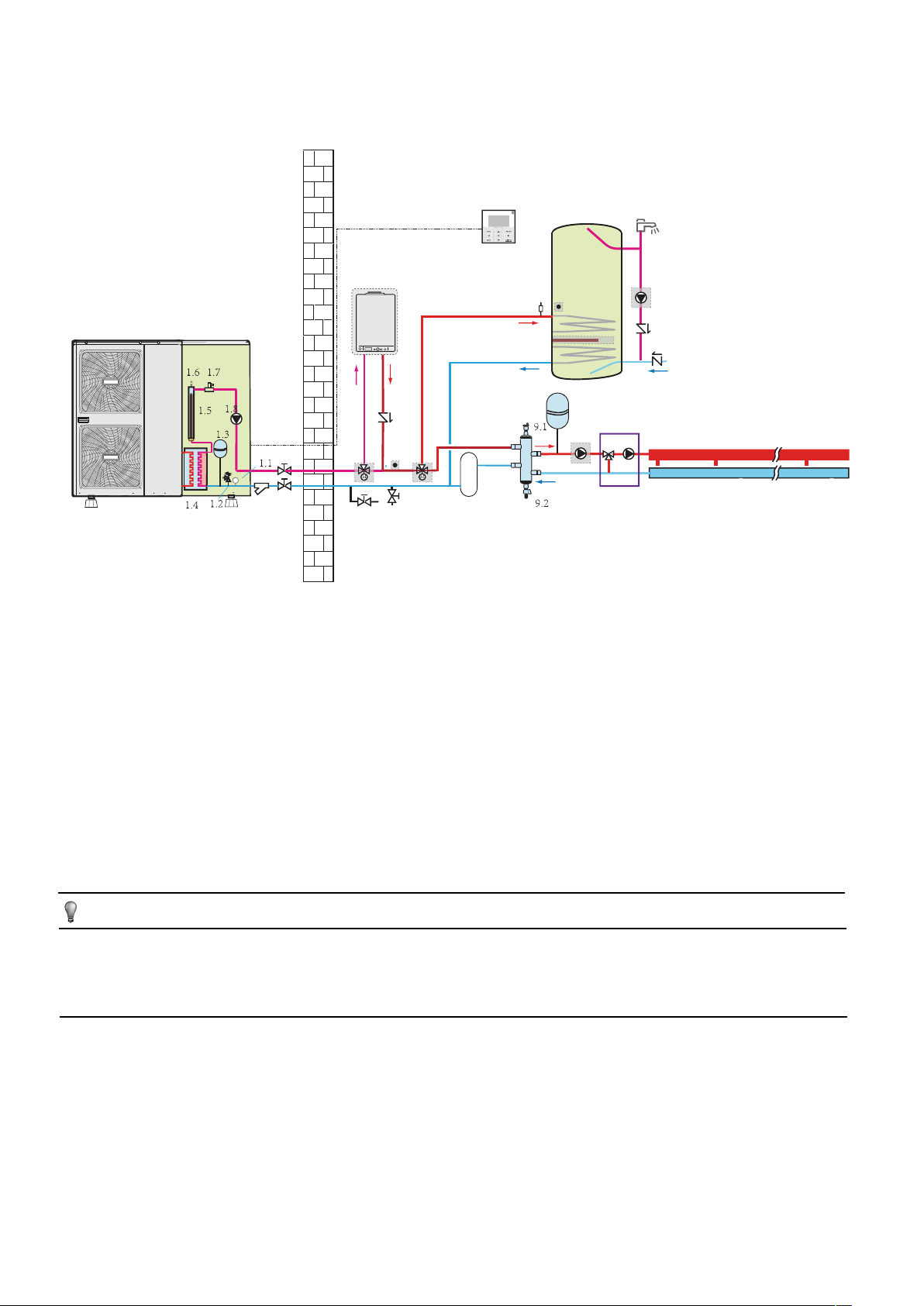
Application b
Boiler provide heat for space heating and domestic water heating.
6
7
AHS
1
23
11
12
9
8
24
FHL1 FHL2 FHLn
4
13
15
16
13.3
14
13.2
13.1
17
17
17
17
19
23
10
11
24.1
12
9
32
7
6
8
24
FHL1 FHL2 FHLn
.......
12
Application c
Boiler provide heat for space heating and domestic water heating, but the boiler and outdoor unit are connect in series.
If application c is selected, the control cable connect to the boiler should also connect to the 3-way valve (25), that is to say the 3-way valve(25)
and boiler should work simultaneously.
1
32
1 outdoor unit
1.1 manometer
1.2 pressure relief valve
1.3 expansion vessel
1.4 plate heat exchanger
1.5 backup heater
1.6 air purge valve
1.7 flow switch
1.8 P_i: circulation pump inside
the unit
2 y-shape filter
3 stop valve (field supply)
4 user interface
6 drain valve(field supply)
7 fill valve(field supply)
AHS
17
23
25
19
8
6 7
8 buffer tank(field supply)
9 balance tank(field supply)
9.1 air purge valve
9.2 drain valve
10 expansion vessel(field supply)
11 P_o: outside circulation pump
(field supply)
12 collector(field supply)
13 domestic hot water tank(field
supply)
13.1 booster heater
13.2 heat exchanger coil
13.3 air purge valve
14 T5:temperature sensor
15 hot water tap(field supply)
4
13
15
16
13.3
14
13.1
13.2
17
17
10
24.1
11
12
9
24
FHL1 FHL2 FHLn
16 P_d: DHW pump(field supply)
17 non-return valve(field supply)
19 SV1: 3-way valve(field supply)
23 T1B: temperature sensor(field
supply)
24 mixing station(field supply)
24.1 P_c: mixing pump
25 3-way valve(field supply)
FHL 1...n floor heating loop
AHS additional heating
source(boiler)
.......
NOTE
If the volume of balance tank(9) is larger than 30L, the buffer tank(8) is unnecessary, otherwise the buffer tank(8) should be installed and the
total volume of balance tank and buffer tank should larger than 30L.. The drain valve (6) should be installed at the lowest positon of the system.
For the 5/7/9kW unit, the backup heater (1.5) is not integrated in the outdoor unit. An independent backup heater can be selected and installed
in the door.Temperature sensor T1B must be installed at the outlet of AHS, and connect to the corresponding port in the main control board of
hydraulic module(refer to 9.2.3 Main control board of hydraulic module).
Operation
When heating is required, either the unit or the boiler starts operating, depending on the outdoor temperature (refer to 10.7 field setting/OTHER
HEATING SOURCE).
■ As the outdoor temperature is measured via the outdoor unit air thermistor, make sure to install the outdoor unit in the shade, so that it is not i
influenced by the sun’s heat.
■ Frequent switching can cause corrosion of the boiler at an early stage. Contact the boiler manufacturer.
■ During heating operation of the unit, the unit will operate to achieve the target water flow temperature set on the user interface. When weather
dependent operation is active, the water temperature is determined automatically depending on the outdoor temperature.
13
■ During heating operation of the boiler, the boiler will operate to achieve the target water flow temperature set on the user interface.
■ Never set the target water flow temperature set point on the user interface above (60°C).
NOTE
Make sure to correctly configure FOR SERVICEMAN in the user interface. Refer to 10.7 Field settings/Other heating source.
CAUTION
■ Ensure that return water to the heat exchanger does not exceed 60°C. Never put the target water flow temperature set point on the
user interface above 60°C.
■ Make sure that the non-return valves (field supply) are correctly installed in the system.
■ The supplier will not be held liable for any damage resulting from failure to observe this rule.
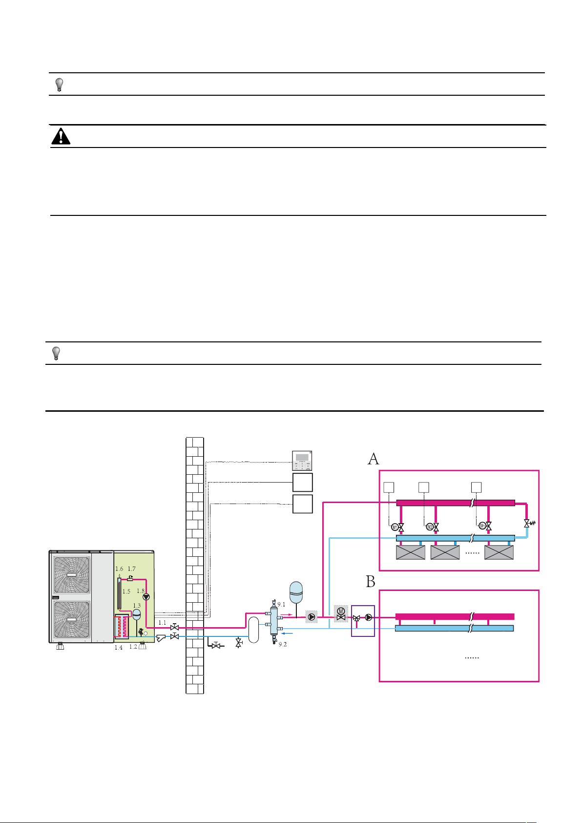
8.6 Application
■ Space heating with two room thermostat application through floor heating loops and fan coil units. The floor heating loops and fan coil units
require different operating water temperatures.
■ The floor heating loops require a lower water temperature in heating mode compared to fan coil units. To achieve these two set points, a
mixing station is used to adapt the water temperature according to requirements of the floor heating loops. The fan coil units are directly
connected to the unit water circuit and the floor heating loops are after the mixing station. Control of this mixing station is not done by the unit.
■ The operation and configuration of the field water circuit is the responsibility of the installer.
■ We only offer a dual set point control function. This function allows two set points to be generated. Depending on the required water
temperature (floor heating loops and/or fan coil units are required) the first set point or second set point can be activated. See 10.7 field setting
/ROOM THERMOSTAT.
NOTE
The wiring of room thermostat 5A(for fan coil units) and 5B(for floor eating loops) should follow 'method C' as described in 9.6.6
Connection for other components/For room thermostat, and the thermostat which connect to port 'C' (in the outdoor unit) should be
placed on the zone where floor heating loops is installed(zone B), the other one connect to port 'H' should be placed on the zone
where fan coil units is installed(zone A).
4
5A
25
T
5B
25
T
1
10
24.1
11
20
T2 TnT1
12
FCUnFCU2FCU1
12
18
32
7 8
6
9
24
FHL1 FHL2 FHLn
14
1 outdoor unit
1.1 manometer
1.2 pressure relif valve
1.3 expansion vessel
1.4 plate heat exchanger
1.5 backup heater
1.6 air purge valve
1.7 flow switch
1.8 P_i: circulation pump in the unit
2 y-shape filter
3 stop valve (field supply)
4 user interface
6 drain valve (field supply)
7 fill valve (field supply)
8 buffer tank (field supply)
9 balance tank (field supply)
9.1 air purge valve
9.2 drain valve
10 expansion vessel (field supply)
11 P_o: outside circulation pump (field supply)
12 collector (field supply)
18 bypass valve (field supply)
20 SV2:2-way valve (field supply)
24 mixing station (field supply)
24.1 P_c: mixing pump
FHL 1...n floor heating loop
FCU 1...n fan coil units
M1...n motorized valve (field supply)
T1…n room thermostat (field supply)
NOTE
If the volume of balance tank(9) is larger than 30L, the buffer tank(8) is unnecessary, otherwise the buffer tank(8) should be installed and the
total volume of balance tank and buffer tank should larger than 30L.The drain valve (6) should be installed at the lowest positon of the system.
For the 5/7/9kW unit, the backup heater (1.5) is not integrated in the outdoor unit. An independent backup heater can be selected and installed
in the door.
The advantage of the dual set point control is that the heat pump will/can operate at the lowest required water flow temperature when only
floor heating is required. Higher water flow temperatures are only required in case fan coil units are operating. This results in better heat pump
performance.
Pump operation and space heating
The pump (1.8) and (11 will operate when there is a request for heating from A and/or B. The outdoor unit will start operating to achieve the
target water flow temperature. The target water leaving temperature depends on which room thermostat is requesting heating.
When the room temperature of both zones is above the thermostat set point, the outdoor unit and pump will stop operating.
NOTE
■ Make sure to correctly configure the room thermostat installation on the user interface. Refer to "10.7 Field settings/ROOM
THERMOSTAT".
■ It is the installers’ responsibility to ensure that no unwanted situations can occur (e.g. extremely high temperature water going towards floor
heating loops, etc.)
■ The supplier does not offer any type of mixing station. Dual set point control only provides the possibility to use two set points.
■ When only zone A requests heating, zone B will be fed with water at a temperature equal to the first set point. This can lead to unwanted
heating in zone B.
■ When only zone B requests heating, the mixing station will be fed with water at a temperature equal to the second set point.Depending on
the control of the mixing station, the floor heating loop can still receive water at a temperature equal to the set point of the mixing station.
■ Be aware that the actual water temperature through the floor heating loops depends on the control and setting of the mixing station.
15
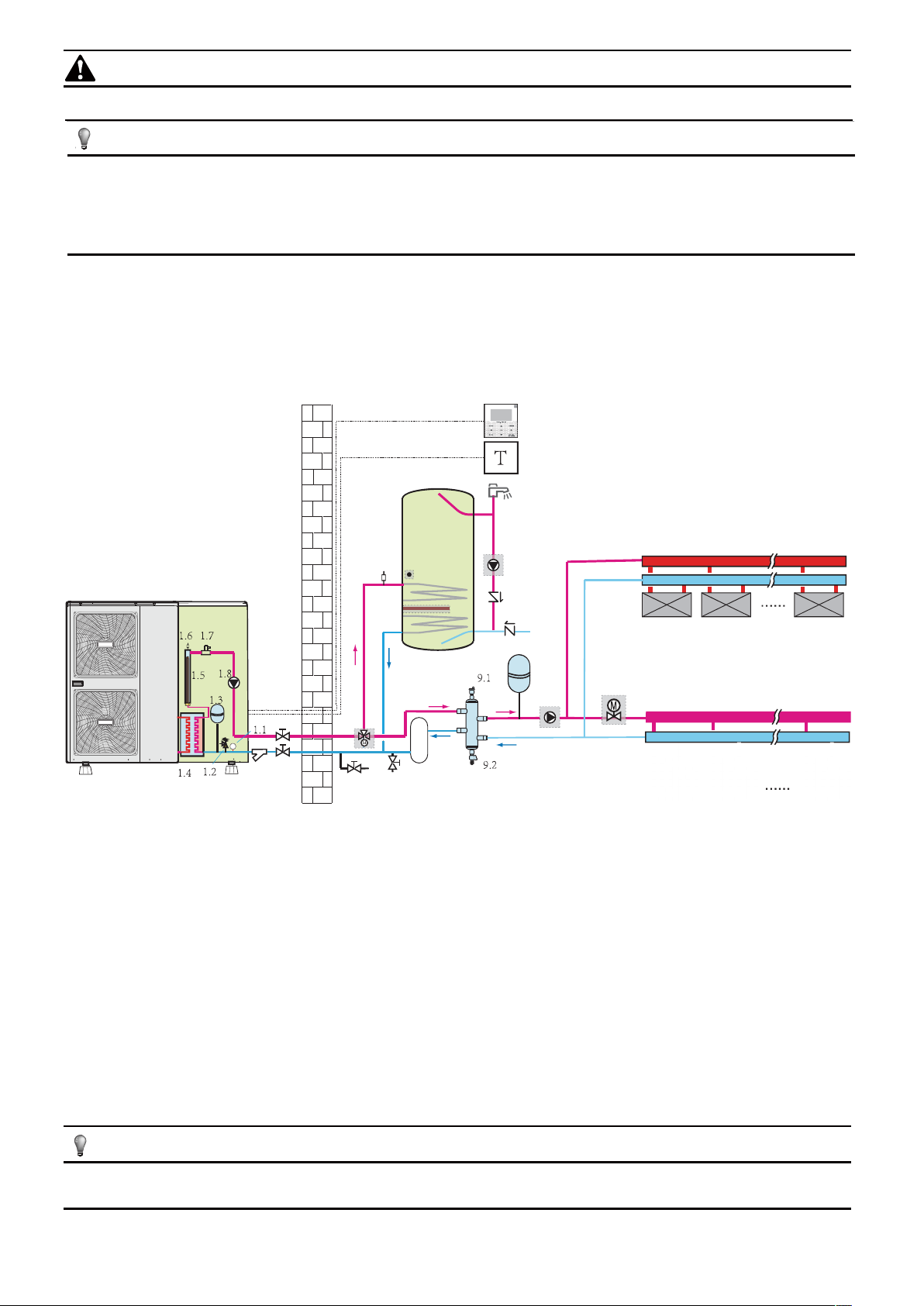
8.7 Application 7
Space cooling and heating application without a room thermostat connected to the unit, but the temperature sensor attached in the user
interface is used to control the ON/OFF of the unit. Heating is provided through floor heating loops. Cooling is provided through the fan coil
units. A 3-way valve is used to change the direction of water flow when the operation mode changed.
4
T2 TnT1
12
18
1
FCUnFCU2FCU1
10
26
11
12
9
32
6
8
7
FHL1 FHL2 FHLn
1 outdoor unit
1.1 manometer
1.2 pressure relif valve
1.3 expansion vessel
1.4 plate heat exchanger
1.5 backup heater
1.6 air purge valve
1.7 flow switch
1.8 P_i: circulate pump in the unit
2 y-shape filter
3 stop valve(field supply)
4 user interface
6 drain valve(field supply)
7 fill valve(field supply)
8 buffer tank(field supply)
9 balance tank(field supply)
9.1 air purge valve
9.2 drain valve
10 expansion vessel(field supply)
11 P_o:outside circulate
pump(field supply)
12 collector(field supply)
18 bypass valve(field supply)
26 3-way valve(field supply)
FHL 1...n floor heating loop
FCU 1...n fan coil units
M1...n motorized valve (field supply)
T1…n room thermostat (field supply)
NOTE
If the volume of balance tank(9) is larger than 30L, the buffer tank(8) is unnecessary, otherwise the buffer tank(8)
should be installed and the total volume of balance tank and buffer tank should larger than 30L.The drain valve (6)
should be installed at the lowest position of the system. For the 5/7/9kW unit. The backup heater (1.5) is not integrated
in the outdoor unit. An independent backup heater can be selected and installed in the door. The wiring of the 3-way
valve (26) should follow the wiring of 2-way valve SV2 (refer to 9.6.6 Connection for other components/ For 2-way
valve SV2).
In normal condition, port A should be opened, while signal sent to the 3-way valve (26), port A will be closed and port B will be opened.
When in cool mode, ON signal will sent from outdoor unit to the 3-way valve (26), the cold water will flow through port inlet to port B, and
port B should connect to the fan coil units. While in heating mode, the hot water will flow through port inlet to port A, and port A should
connect to the floor heating loops. In this way, all the water from the unit will flow through the floor heating loops and thus ensure better
performance of the floor heating.
As the temperature sensor is used to detect the room temperature, the user interface (4) should be placed in the room where floor
heating loops and fan coil units is installed and away from the heating source. Correct configuration should be applied in the user
interface (refer to 10.7 field settings/TEMP. TYPE SETTING). The target room temperature can be set on the main page of user
interface, the target outlet water temperature will be calculated from climate related curves, the unit will turn off when the room
temperature reaches the target temperature.
inlet
B
A
16
8.8 Application 8
Space heating application and domestic hot water heating with a solar energy kit connect to the system, space heating is provided by heat
pump, domestic hot water heating is provided by heat pump and solar energy kit.
SP
13
15
27
28
4
1
1 outdoor unit
1.1 manometer
1.2 pressure relif valve
1.3 expansion vessel
1.4 plate heat exchanger
1.5 backup heater
1.6 air purge valve
1.7 flow switch
1.8 P_i: circulate pump in the unit
2 y-shape filter
3 stop valve(field supply)
19
9
32
6
4 user interface
6 drain valve(field supply)
7 fill valve(field supply)
8 buffer tank(field supply)
9 balance tank(field supply)
9.1 air purge valve
9.2 drain valve
10 expansion vessel(field supply)
11 P_o: outside circulate pump(field supply)
12 collector(field supply)
13 domestic hot water tank(optional)
8
7
10
14
13.3
13.3
13.2
12
11
FHL1 FHL2 FHLn
13.1 booster heater
13.2 heat exchanger coil
13.3 air purge valve
14 T5:temperature sensor
15 hot water tap(field supply)
16 P_d: DHW pump(field supply)
17 non-return valve(field supply)
18 bypass valve(field supply)
19 SV1: 3-way valve(field supply)
FHL 1...n floor heating loop
27 Solar energy kit(field supply)
28 P_s: Solar pump(field supply)
13.1
16
17
17
18
NOTE
If the volume of balance tank(9) is larger than 30L, the buffer tank(8) is unnecessary, otherwise the buffer tank(8) should be installed and the total
volume of balance tank and buffer tank should larger than 30L.The drain valve (6) should be installed at the lowest positon of the system. For
the 5/7/9kW unit, the backup heater (1.5) is not integrated in the outdoor unit. An independent backup heater can be selected and installed in the door.
The pump (1.8) and (11 will operate when there is a request for heating floor heating loops. The outdoor unit will start operating to achieve the
target water flow temperature. The target water can be set in the user interface.
if solar energy is set avaliable in the user interface(refer to 10.7 Field settings/OTHER HEATING SOURCE ), the heating of domestic hot water
can be done by either the solar energy kit or heat pump. when the solar energy kit turns on, signal will sent to the outdoor unit, then the pump
(28) will operate, the heat pump will stop heating for domestic hot water during solar energy kit operation .
NOTE
Make sure to wiring the solar energy kit(27) and solar pump(28) correctly, refer to “9.6.6 Connection for other components/For solar energy
kit”. User interface should be correctly configured, refer to “10.7 Field settings/OTHER HEATING SOURCE”.
17
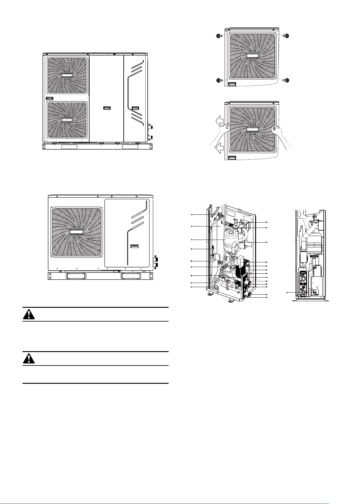
9 OVERVIEW OF THE UNIT
9.1 Opening the unit
1 2
Door 1 gives access to the compressor compartment and electrical
parts.
Door 2 gives access to the hydraulic compartment and electrical
parts.
9.2 Main components
9.2.1 Hydraulic compartment
WARNING
Switch off all power — i.e. unit power supply and backup heater
and domestic hot water tank power supply (if applicable) —
before removing doors 1 and 2.
CAUTION
Parts inside the unit may be hot.
Push the grill to the left until it stops. then pull its right edge, the grill
can now be removed. You can also reverse the procedure. Exercise
caution to avoid a possible hand injury.
1
9
15.3
T1
6.3
10
TW_out
6.4
11
15.1
15.2
12.1
12
13
TW_in
6.5
14
14.1
6.1
6.2
2
3
4
5
T2B
T2
7
8
1-phase 10~16kW
3-phase 12~16kW
1.Air purge valve
Remaining air in the water circuit will be automatically removed via
the air purge valve.
2.Backup heater
The backup heater consists of an electrical heating element that
will provide additional heating capacity to the water circuit if the heating
capacity of the unit is insufficient due to low outdoor temperatures.
It also protects the external water piping from freezing.
3.Expansion vessel (1.32 gallons (5 L))
4.Pressure Sensor
5.Refrigerant gas connection
6.Temperature sensors
Four temperature sensors determine the water and refrigerant
temperature at various points in the water circuit.
6.1-T2B; 6.2-T2; 6.3-T1; 6.4-TW_out; 6.5-TW_in
7.Refrigerant liquid connection
8.Manometer
The manometer provides a water pressure readout of the water
circuit
18
9.Flow switch
The flow switch checks the flow in the water circuit and protects
the
heat exchanger against freezing and the pump against damage.
10.Pump
The pump circulates the water in the water circuit.
11.Heat exchanger
The manometer provides a water pressure readout of the water
circuit.
12.Water outlet connection
12.1 Air purge valve
13.Pressure relief valve
The pressure relief valve prevents excessive water pressure in
the water circuit by opening at 43.5 psi (3 bar) and discharges
water.
14.Water inlet connection
14.1 Drain valve
15.Electrical heating tape(15.1-15.3)
1
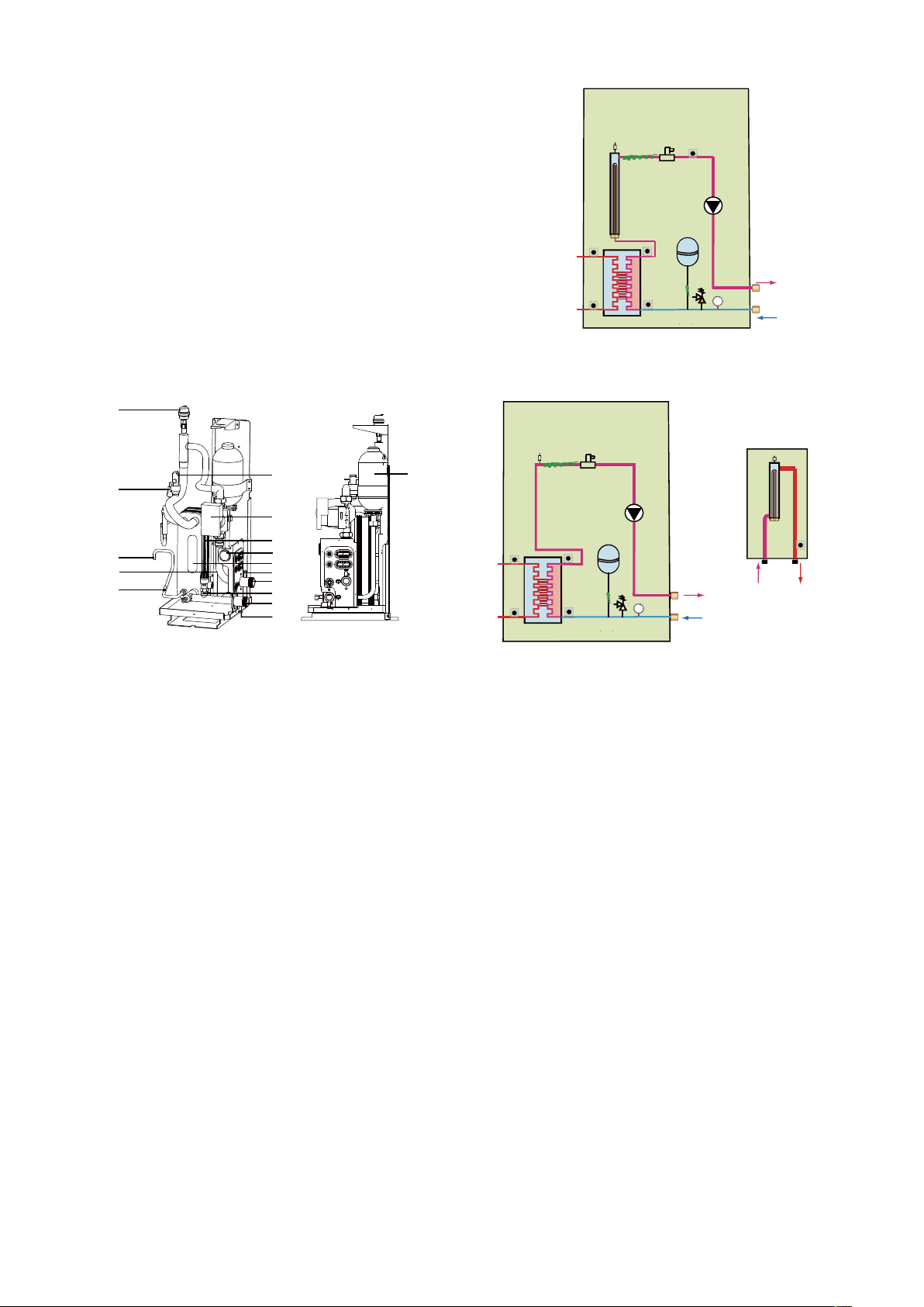
9.2.2 Functional diagram of hydraulic compartment
9
TW_in
11
3
T1
15.2
10
12
14
813
1
15.3
2
T2B
5
T2
7
TW_out
15.1
1-phase 10~16kW
3-phase 12~16kW
9
3
4
10
11
7
18
6
8
15.1
12.1
12
13
14
14.1
1-phase 5/7/9kW
1.Air purge valve
Remaining air in the water circuit will be automatically removed via
the air purge valve.
3.Expansion vessel (0.88gallons (2 L))
4.Pressure Sensor
6.Temperature sensors
Four temperature sensors determine the water and refrigerant
temperatures at various points in the water circuit.
7.Refrigerant liquid connection
8.Manometer
The manometer provides a water pressure readout of the water
circuit.
9.Flow switch
The flow switch checks the flow in the water circuit and protects the
heat exchanger against freezing and the pump against damage.
10.Pump
The pump circulates the water in the water circuit.
11.Heat exchanger
12.Water outlet connection
12.1 Air purge valve
13.Pressure relief valve
The pressure relief valve prevents excessive water pressure in
the water circuit by opening at 43.5 psi (3 bar) and discharging
water.
14.Water inlet connection
14.1 Drain valve
15.1.Electrical heating tape
18. sleeve for insert temperature sensor
15.3
9
1
2
10
TW_out
T2B
5
3
T1
16 17
15.2
15.1
TW_in
11
813
T2
7
12
14
backup heater box
(optional)
1-phase 5/7/9kW
1 Air purge valve
2 Backup heater vessel with backup heater
3 Expansion vessel
5 Refrigerant gas connection
7 Refrigerant liquid connection
8 Manometer
9 Flow switch
10 Circulation Pump
11 Heat exchanger
12 Water outlet connection
13 Pressure relief valve
14 Water inlet connection
15.1 Electrical heating tape
15.2 Electrical heating tape
15.3 Electrical heating tape
16 Water inlet connection
17 Water outlet connection
Temperature sensors:TW_in;TW_out;T2B;T2;T1
NOTE:for 5/7/9 kW unit,If backup heater box is installed, the port
(CN6) for T1 in the main control board of hydraulic should connect
to the corresponding port in the backup heater box(please refer to
the Installation & Owner’s Manual of backup heater box).
if backup heater box is not installed, the T1 sensor should insert into
the sleeve which near the pump(10) and connect to the port CN6.
19

Control box for 5/7/9 kW UNIT
Control box for 10~16KW UNIT
PCB A PCB B
Main control board
of hydraulic module
The image shown here is indicative only. If there is inconsistency between the image and the actual product, the actual product shall govern.
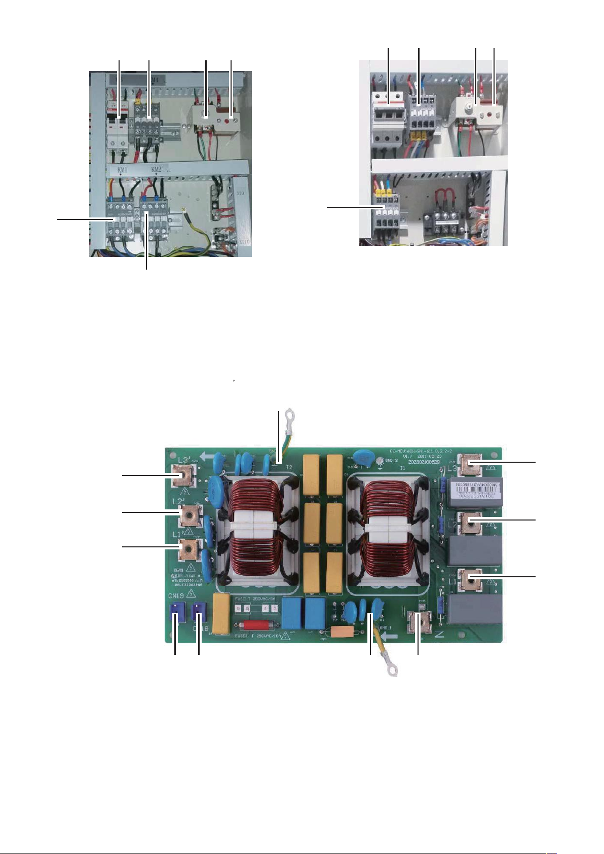
9.2.3 Main control board of hydraulic module
PCB B PCB A
PCB C
(at back of the PCB B,only for 3 phase unit)
1
main control board
of hydraulic module
765432
27
26
25
24
23
2
8
9
10
11
12
13
14
1-phase 5/7/9kW
1-phase 10~16kW
3-phase 12~16kW
1 Input port for solar energy(CN5)
2 Output port for transformer(CN4)
3 Power supply port for user interface(CN36)
4 Port for remote switch(CN12)
5 Port for flow switch(CN8)
6 Communicate port between this PCB and user interface(CN14)
8 Port for temperature sensors(TW_out, TW_in, T1, T2,T2B )(CN6)
9 Port for temperature sensor(T5, domestic hot water tank temp.)
(CN13)
10 Port for temperature sensor(T1B, the final outlet temp.)(CN15)
11 Digital displays(DIS1)
12 Check button(SW4)
13 DIP switch(S1,S2)
14 output port for deforst(CN34)
15 Port for anti-freeze eletric heating tape (internal)(CN40)
20
151718 1619202122
16 Port for anti-freeze eletric heating tape (internal)(CN41)
17 Output port for external heating source / operation output port(CN25)
18 Port for anti-freeze eletric heating tape(external) /port for solar
energy pump/output port for remote alarm(CN27)
19 Port for external circulted pump P_o)/pipe pump P_d /mix
pump(P_c)/2-way valve SV2(CN37)
20 Port for SV1(3-way valve) and SV3(CN24)
21 Port for internal pump(CN28)
22 Input port for transformer(CN20)
23 Feedback port for temperature switch(CN1)
24 Port for power supply(CN21)
25 Feedback port for external temp. switch(shorted in default)(CN2)
26 Control port backup heater/booster heater(CN22)
27 Control port for room thermostat(CN3)

9.2.4 PCB for refrigerant system
PCB A, Inverter module for 1-phase 10~16kW unit
10
9
8
7
6
11 13
12
1 Reserved(CN2)
2 Input Port N For IPM Module(N)
3 Power Supply Of W Phase For
Compressor(W)
4 Power Supply Of V Phase For Compressor(V)
PCB B, Main control board for 1-phase 10~16kW unit
1
2
6 Output Port N Of PFC Module(N_1)
7 Output Port P Of PFC Module(P_1)
8 Input Port For PFC Inductance L_1(L_1)
9 Input Port For PFC Inductance L_2(L_2)
3 4 5 6 7 8
20
23
22
21
19
18
25
345
2
1
10 Input Port N For PFC Module(VIN-N)
11 Input Port P For IPM Module(P)
12 Communicate Port Between PCB A
And PCB B(CN1)
13 +15V(CN6)
9 10
24
17
16
1 Port For Pressure Switc
3 Port For Pressure Sensor(CN28)
4 Port For Discharge Temperature
Sensor(CN8)
5 Port For Ambient Temperature And
Condenser Outlet Temperature
Sensor(CN9)
15 2614 13 12
7 Reserved(CN30)
9 Input Port For Live Wire(CN1)
10 Input Port For Neutral Wire(CN2)
11 Output Port For Neutral Wire(CN3)
12 Ourput Port For Live Wire(CN4)
13 Reserved(CN7)
14 Port For 4-way Value(CN13)
15 Port For Eletric Heating Tape(CN14)
16 Input Port For Transformer(CN26)
21
11
17 Power Supply Port For Fan(CN18)
18 Port For Down Fan(CN19)
19 Port For Up Fan(CN17)
20 Output Port For Transformer(CN51)
21 Check Button(SW2)
22 Refrigerant Recovery Button
23 Digital Displays(DIS1)
24 Ground Wire(CN11)
25 Comunication Port For PCB A(CN6)
26 Power supply port for hydro-box
control board(CN16)
Controls parts for backup heater(IBH)
5
1-phase 10~16kW
6
1 Auto thermal protector
2 Manu thermal protector
3 Backup heater contactor KM4
4 Backup heater circuit breaker CB
5 Backup heater contactor KM1
6 Backup heater contactor KM2
1-phase 10~16kW
1234
1234
5
3-phase 12~16kW
1 Auto thermal protector
2 Manu thermal protector
3 Backup heater contactor KM4
4 Backup heater circuit breaker CB
5 Backup heater contactor KM1
PCB C, filter board for 3 phase 12~16kw unit, door 1
10
9
8
11
PCB C
3-phase 12~16kW
1
2
3
4567
1 Power supply L3(L3)
2 Power supply L2(L2)
3 Power supply L1(L1)
4 Power supply N(N)
5 Ground wire(GND_1)
6 Power supply for load(CN18)
7 Power supply for main control board(CN19)
8 Power filtering L1(L1’)
9 Power filtering L2(L2’)
10 Power filtering L3(L3’)
11 Ground wire(GND_2)
22

PCB B, Main control board for 3-phase 12~16kW unit
1 24 225
3 4
5.15.2
6.1
6.2
7
10
11
23
1 Power supply for the main PCB(CN250)
2 Port for pressure sensor(CN36)
3 Port for sunction temperature sensor(CN4)
4 Port for discharge temperature sensor(CN8)
5.1 Port for outdoor temperature sensor(CN9)
6.1 Port for high pressure switch(CN6)
6.2 Port for low pressure switch(CN6)
PCB A, Inverter module for 3-phase 12~16kW unit
8
1921 2022
11 Port for power supply(CN41)
12 Power supply for hydro-box
control board(CN6)
13 PFC control port(CN63)
14 Reserved(CN64)
15 Port for 4-way value(CN65)
16 Port for eletric heating tape(CN66)
17 PTC control(CN67)
1
2
13 121415161718
18 Reserved(CN68)
19 Port for down fan(CN19)
20 Port for up fan(CN17)
23 Port for voltage check(CN205)
24 Refrigerant recovery button(SW1)
25 Check button(SW2)
3 4567
1. +15V port(CN4)
2. To MCU(CN1)
3. IPM input N
4. Compressor connection port W
5. Compressor connection port V
6. Compressor connection port U
7. IPM input P
8. Power for switching power supply(CN2)
3-phase PCB A
23

PCB A, Inverter board for 1 phase 5/7/9 kW unit.
11
1
10
2
9
3
8
4567
1-phase 5/7/9kW
1 To main board (CN101,CN105)
2 Compressor connection port U V W (U,V,W)
3 Input port N for IPM module(N)
4 Input port P for IPM module(P)
5 Input port for PFC inductance P1(P1)
6 Input port for bridge Rectifiers(P5)
7 Input port for Bridge Rectifiers(P6)
8 Output port P of PFC(P2)
9 Input port for PFC inductance 3(P3)
10 Output port N of PFC(P4)
11 +18V(P9)
24

PCB B, Main control board for 1 phase 5/7/9 kW unit.
18
17
16
15
1
2
3
14
13
12
1-phase 5/7/9kW
1 Rectifier bridge input port L
2 Hydraulic compartment input port2
3 Rectifier bridge input port N
4 Power supply N
5 Power supply L
6 Transformer output port
7 BLACK: T3 temperature sensor port
WHITE:T4 temperature sensor port
8 TP temperature sensor port
9 YELLOW: High pressure switch
RED: Low pressure switch
PCB A
4
567891011
10 Th temperature sensor port
11 Pressure sensor port
12 Port for communication between this PCB and main control
board of hydraulic module
13 P/N/+18V port
14 To IPDU/PFC
15 DC fan port
16 Compression electromechanical heating belt
17 4-way valve port
18 Transformer input port
25
9.3 Water pipework
All piping lengths and distances have been taken into consideration.
Requirements
Valve
The maximum allowed thermistor cable length is 20m.
This is the maximum allowable distance between the
domestic hot water tank and the unit (only for
installations with a domestic hot water tank).The
thermistor cable supplied with the domestic hot water
tank is 10m in length.
In order to optimize efficiency we recommend installing
Thermistor
cable
length
minus 2m
the 3-way valve and the domestic hot water tank as
close as possible to the unit
NOTE
■ If the installation is equipped with a domestic hot water tank
(optional), please refer to the domestic hot water tank
Installation & Owner's Manual.
■ If there is no glycol (anti-freeze) in the system there is a power
supply or pump failure, drain the system (as shown in the figure
below).
Before continuing installation of the unit, check the following:
■ The maximum water pressure = 3 bar.
■ The maximum water temperature is 70°C according to safety
device setting.
■ Always use materials that are compatible with the water used in the
system and with the materials used in the unit.
■ Ensure that components installed in the field piping can withstand
the water pressure and temperature.
■ Drain taps must be provided at all low points of the system to
permit complete drainage of the circuit during maintenance.
■ Air vents must be provided at all high points of the system. The
vents should be located at points that are easily accessible for
servicing. An automatic air purge is provided inside the unit. Check
that this air purge valve is not tightened too much so that automatic
release of air in the water circuit remains possible.
Checking the water volume and expansion vessel pre-pressure
The unit is equipped with a 5 L(for 5/7/9 kW unit, the volume is 2L)
expansion vessel that has a default pre-pressure of 1.5 bar.
To assure proper operation of the unit, the pre-pressure of the expansion
vessel might need to be adjusted and the minimum and maximum water
volume must be checked.
1. Check that the total water volume in the installation, excluding the
internal water volume of the unit, is at least 25L(for 5/7/9 kW unit,
the minimum volume is 15L) . Refer to 14 Technical specifications
to find the total internal water volume of the unit.
A
<A
When water is not moving inside the system in cold
weather, freezing is very likely and will damage
the system.
Checking the water circuit
The units are equipped with a water inlet and outlet for connection
to a water circuit. This circuit must be provided by a licensed technician
and must comply with local laws and regulations.
The unit is only to be used in a closed water system.
Application in an open water circuit can lead to excessive
corrosion of the water piping.
Example
NOTE
■ In most applications this minimum water volume will be
satisfactory.
■ In critical processes or in rooms with a high heat load though,
extra water might be required.
■ When circulation in each space heating loop is controlled by
remotely controlled valves, it is important that this minimum
water volume is kept even if all the valves are closed.
1 Outdoor Unit
1.1 Manometer
1.2 Pressure Relief Valve
1.3 Expansion Vessel
1.4 Plate Heat Exchanger
1.5 Backup Heater
1.6 Air Purge Valve
1.7 Flow Switch
1.8 P_i: Circulation Pump Inside Unit
2 Y-shape Filter
3 Stop Valve (Field Supply)
4 User Interface
6 Drain Valve(Field Supply)
7 Fill Valve(Field Supply)
8 Buffer Tank(Field Supply)
9 Balance Tank(Field Supply)
9.1 Air Purge Valve
9.2 Drain Valve
10 Expansion Vessel (Field
Supply)
11 P_o: Outside Circulation Pump
(Field Supply)
12 Collector(Field Supply)
18 Bypass Valve(Field Supply)
Fhl 1...N Floor Heating Loop
M1...N Motorized Valve (Field
Supply)
T1…n Room Thermostat (Field
Supply)
26
2. Using the table below, determine if the expansion vessel
pre- pressure requires adjustment.
3. Using the table and instructions below, determine if the total
water volume in the installation is below the maximum allowed
water volume.
≤12 m
>12 m
(a) Installation height difference: height difference (m) between the
highest point of the water circuit and the unit. If the unit is located
at the highest point of the installation, the installation height is
considered to be 0 m.
(b) for 1-phase 10~16kW and 3-phase 12~16 kW unit, this value is
125L, for 5~9 kW unit, this value is 45 L.
Calculating pre-pressure of the expansion vessel
The pre-pressure (Pg) to be set depends on the maximum installation
height difference (H) and is calculated as follows:
Pg(bar)=(H(m)/10+0.3) bar
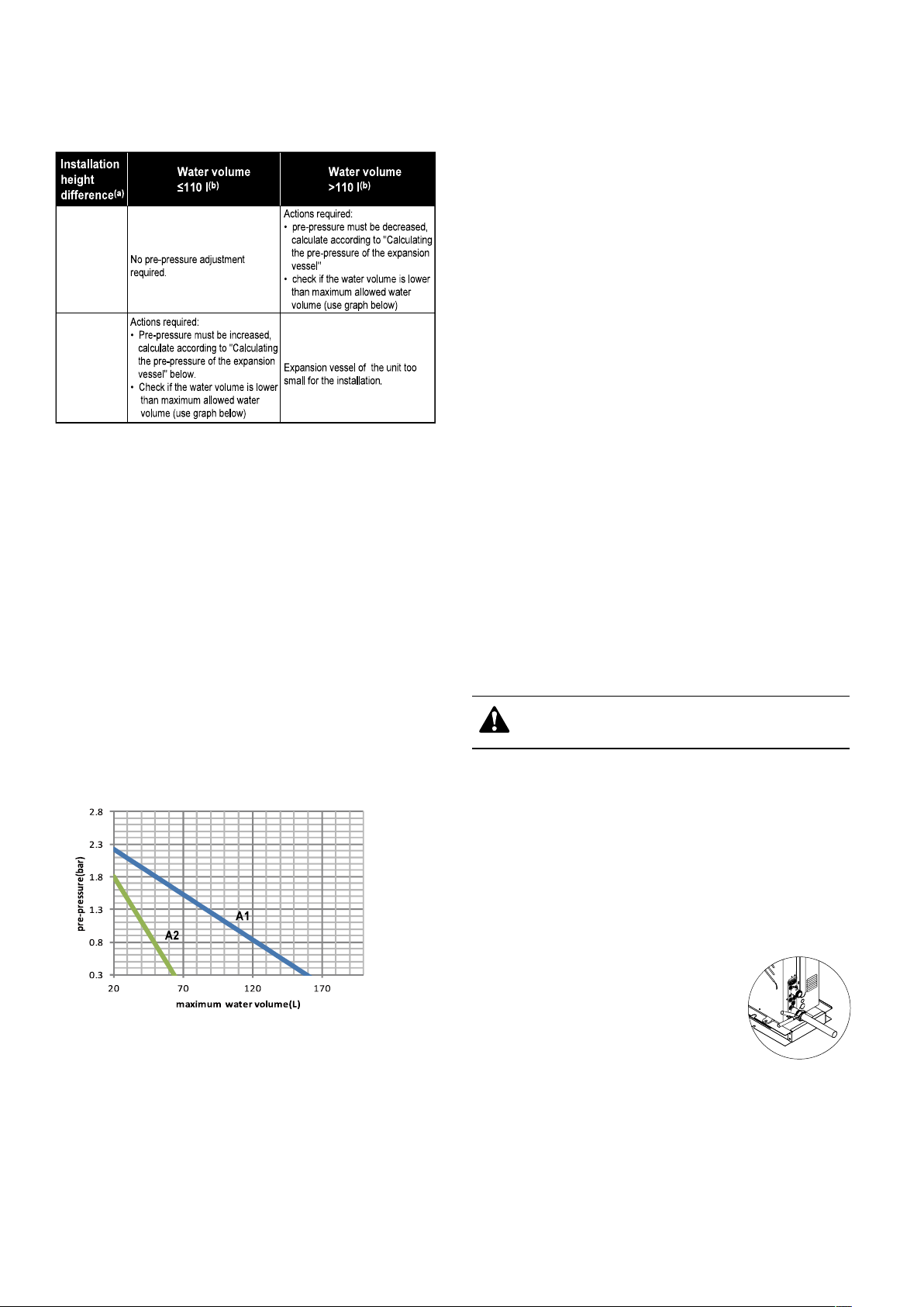
Checking the maximum allowed water volume
To determine the maximum allowed water volume in the entire circuit,
proceed as follows:
1. Determine the calculated pre-pressure (Pg) for the corresponding
maximum water volume using the graph below.
2. Check that the total water volume in the entire water circuit is
lower than this value.
If this is not the case, the expansion vessel inside the unit is too small
for the installation.
pre-pressure = pre-pressure of the expansion vessel
maximum water volume = maximum water volume in the system
Example 1
The unit(16kW) is installed 10m below the highest point in the water
circuit. The total water volume in the water circuit is 100 L.
In this example, no action or adjustment is required.
Example 2
The unit(16kW) is installed at the highest point in the water circuit.
The total water volume in the water circuit is 150 L.
Result:
■ Since 150 L is more than 110 L, the pre-pressure must be
decreased (see table above).
■ The required pre-pressure is:
Pg(bar) = (H(m)/10+0.3) bar = (0/10+0.3) bar = 0.3 bar
■ The corresponding maximum water volume can be read from
the graph: approximately 160 L.
■ Since the total water volume (150 L) is below the maximum water
volume (160 L), the expansion vessel suffices for the installation.
Setting the pre-pressure of the expansion vessel
When it is required to change the default pre-pressure of the
expansion vessel (1.5 bar), keep in mind the following guidelines:
■ Use only dry nitrogen to set the expansion vessel pre-pressure.
■ Inappropriate setting of the expansion vessel pre-pressure will
lead to malfunctioning of the system. Pre-pressure should only be
adjusted by a licensed installer.
Selecting the additional expansion vessel
If the expansion vessel of the unit is too small for the installation, an
additional expansion vessel is needed.
■calculate the pre-pressure of the expansion vessel:
Pg(bar)=(H(m)/10+0.3) bar
the expansion vessel equipped in the unit should adjust the prepressure also.
■calculate the volume needed of the additional expansion vessel:
V1=0.0693*Vwater/(2.5-Pg)-V0
Vwater is volume of water in the system, V0 is volume of expansion
vessel which the unit is equipped(10~16kW,V0=5L, 5~9kW,V0=2L).
Connecting the water circuit
Water connections must be made in accordance with the outlook
diagram delivered with the unit, with respect to the water intake and
water outlet.
If air, moisture or dust gets in the water circuit, problems may occur.
Therefore, always take into account the following when connecting
the water circuit:
■ Use clean pipes only.
■ Hold the pipe end downwards when removing burrs
■ Cover the pipe end when inserting it through a wall so that no dust
and dirt enter.
■ Use a good thread sealant for sealing the connections. The
sealing must be able to withstand the pressures and temperatures
of the system.
■ When using non-brass metallic piping,make sure to insulate both
materials from each other to prevent galvanic corrosion.
■ Because brass is a soft material, use
appropriate tools for connecting the water
circuit.
Inappropriate tools will cause damage
to the pipes.
Be careful not to deform the unit’s piping by using excessive
force when connecting the piping. Deforming the piping can
cause the unit to malfunction.
A1 System without glycol for 1-phase 10~16 kW and 3-phase
12~16 kW unit
A2 System without glycol for the 5/7/9 kW unit
27
 Loading...