

Page 1
Midea
Cooker Hood
Instructions
MODEL: MHC60GSS
MHC90GSS
Read the instructions carefully before using your cooker hood, and keep them carefully.
If you follow the instructions, your cooker hood will serve you many years well.
SAVE THESE INSTRUCTIONS CAREFULLY
Page 2
RECOMMENDATIONS AND SUGGESTIONS
The instructions apply to several versions of this appliance. Accordingly, you may nd
descriptions of individual features that do not apply to your appliance.
INSTALLATION
● The manufacturer will not be held liable for any damages resulting from incorrect or
improper installation.
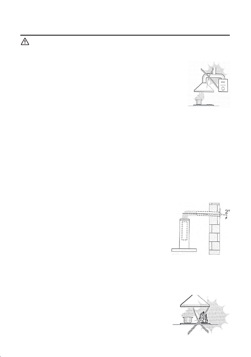
● The minimum distance between the supporting surface for the cooking vessels on the
hob and the lowest part of the cooker hood. (When the cooker hood is located above
a gas appliance, the distance shall be at least 65 cm. If the installation instructions for
the gas hob specify a greater distance, it has to be taken into account. The distance
of 65 cm can be reduced for non-combustible parts of the cooker hood and parts
operating at safety extra low voltage, provided these parts do not give access to live
parts if deformed.)
● Check that the mains voltage corresponds to that indicated on the rating plate xed to
the inside of the hood.
● For Class I appliances, check that the domestic power supply guarantees adequate earthing.
● Connect the extractor to the exhaust ue through a pipe with the minimum diameter of 120 mm.
● The route of the ue must be as short as possible.
● The air must not be discharged into a ue that is used for exhausting fumes from appliances, burning gas or
other fuels.
● If the extractor is used in conjunction with non-electrical appliances (e.g. gas burning appliances), a sufcient
degree of aeration must be guaranteed in the room in order to prevent backow of the exhaust gas. The
kitchen must have an opening communicating directly with the open air in order to guarantee the entry of
clean air.
● When the cooker hood is used in conjunction with appliances supplied with energy other than electric, the
negative pressure in the room must not exceed 0.04 mbar to prevent fumes being drawn back into the room
by the cooker hood.
● If the supply cord is damaged, it must be replaced by the manufacturer, its service agent or similarly qualied
persons in order to avoid a hazard.
● Regulations concerning the discharge of air have to be fullled.
USE
● The cooker hood is only for home use, not suitable for barbecue, roast shop
and other commercial purposes.
● Never use the hood for purposes other than those intended.
● Never leave high naked ames under the hood when it is in operation.
● Adjust the ame intensity to direct the the ame upto the bottom of a pan only,
making sure that it does not engulf the sides.
● Deep fat fryers must be continuously monitored during use: overheated oil
can burst into ames.
● Do not ame under the cooker hood, with a risk of re.
● This appliance can be used by children aged 8 and above and persons with
reduced physical, sensory or mental capabilities or lacking experience and
knowledge if they have been given supervision or instruction concerning use of the appliance in a safe way
and understood the hazards involved.
● Children should be supervised to ensure that they do not play with the appliance.
● Cleaning and maintenance shall not be made by children without supervision.
● “CAUTION: Accessible parts may become hot when used with cooking appliances”.
MAINTENANCE
● The cooker hood and its lter should be cleaned regularly according to the
instructions.
● Switch off or unplug the appliance from the mains supply before carrying out
any maintenance work.
● Clean and/or replace the lters after the specied period (re hazard).
● Clean the hood using a damp cloth and a neutral liquid detergent.
● The appliance uses 4 hob elements at most.
2
Page 3

COMPONENTS
Ref. Qty. Product Components
1 1
2.1 1 Lower Decorative Chimney
2.2 1 Upper Decorative Chimney
4 1 Exhaust Pipe
5 2 Activated Charcoal Filter (optional)
Ref. Qty. Installation Components
10 7 Screws 5x50
11 7 Wall Plug
12 6 Screw 4,2x9,5/2 Spare
13 4 Screw M4 x 20
14 4 Decorative Washer
15 4 Spare
20 1 Hood Fixing Bracket (optional )
21 2 Chimney Fixing Bracket (0 / 1 optional)
Hood Body, complete with Control,
Light, Blower, Filter.
2.2
2.1
1
20
21
12
13
4
3
5
10
11
Qty. Documentation
1 Instruction Manual
15
14
3
Page 4
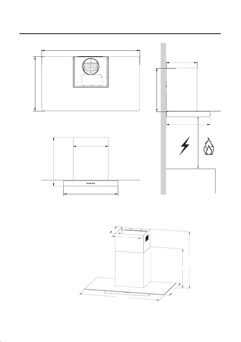
COMPONENTS
500
600/900
282
391
401
322
448
500
282
322
600/900
500
Min.
650mm
min.
448
max.
828
448
Min.
650mm
4
Page 5

INSTALLATION
WALL DRILLING AND BRACKET FIXING
As the rst step, proceed with the following drawings:
● A vertical line up to the ceiling or up to the upper limit, at the center of the area in which the
hood is to be tted.
● A horizontal line A at 1083-1183 mm above the cooker top.
● A horizontal line B at 30-377 mm above the horizontal line A.
● A horizontal line C at 118 mm below the horizontal line A.
Mark points:
● Mark a point (1) on the horizontal line A, 60 mm to the vertical reference line.
● Repeat this operation on the other side and on the vertical reference line, checking that the
three marks are on one horizontal line.
● Mark a point (2) on the horizontal line B, 60 mm to the vertical reference line.
● Repeat this operation on the other side, checking that the two marks are on one horizontal line.
5
Page 6

● Mark a point (3) on the horizontal line C, 80 mm to the vertical reference line.
● Repeat this operation on the other side, checking that the two marks are on one horizontal line.
Fix the brackets (optional):
● Drill holes at the marked points with a ɸ10 mm drill bit.
● Insert the wall plugs 11 into the holes.
● Fix the hood xing bracket 20 with 3 screws 10 (5 x 50) at the horizontal line A,
● Fix the chimney xing bracket 21 with 2 screws 10 (5 x 50) at the horizontal line B.
Hook the hood body
Hook the hood body to the bracket 20.
Level the hood body itself.
Lock screws (M5*12) into the hood xing bracket to prevent the hood body from accidentally sliding off.
Remove the lter from the inside of the hood body, and x the screw 10 to wall plug 11 at the point
(3) (optional).
Right Wrong
CONNECTIONS
DUCTED VERSION AIR EXHAUST SYSTEM
When installing the ducted version, connect the hood to the
chimney using either a exible or a rigid pipe of ɸ 150 or ɸ 120 mm,
the choice of which is left to the installer.
● Insert the reducer ange 3 onto the hood body outlet to install a
ɸ 120 mm air exhaust connection.
● Fix the pipe 4 in place using sufcient pipe clamps (not
supplied).
● Remove possible charcoal lters.
6
Page 7

CHIMNEY ASSEMBLY
The chimney can only be installed with an exhausting hood.
Lower decorative chimney
● Fix the chimney xing bracket 21 onto the lower decorative chimney with 2 screws
12 (4.2 x 9.5) supplied with the hood.
21
2.1
12
Upper Decorative Chimney
● Slightly widen the two sides of the upper chimney and hook them between the wall and the
bracket 21 which is xed on the lower decorative chimney.
● Fix the upper chimney onto the bracket 21 with 2 screws 12 (4.2 x 9.5) supplied with the hood.
7
Page 8

USE
MOTOR OFF SWITCH: Press this switch to stop the motor.
SPEED SWITCH: Press this switch, and the motor runs at LOW speed.
SPEED SWITCH: Press this switch, and the motor runs at MEDIUM speed.
SPEED SWITCH: Press this switch, and the motor runs at HIGH speed.
LIGHT ON/OFF SWITCH: Press this switch to turn on the light, and press again
to turn it off.
8
Page 9

MAINTENANC
GREASE FILTER
METAL SELF-SUPPORTING GREASE FILTER CLEANING
● The lters must be cleaned every 2 months of operation or more
frequently for particularly heavy usage, and can be washed in a
dishwasher.
● Pull the comfort panel to open them.
● Remove the lters one by one by pushing them towards the back side
of the hood unit and simultaneously pulling downwards.
● Any kind of bending of the lters has to be avoided when washing
them. Before tting them again into the hood, make sure that they are
completely dry. (The color of the lter surface may change over time,
but this has no inuence to the lter efciency).
● When tting the lters into the hood, pay attention that they should be
mounted in correct position with the handle facing outwards.
● Close the comfort panel.
ACTIVATED CHARCOAL FILTER (RECIRCULATION VERSION)
These lters are not washable and cannot be regenerated, and must be replaced approximately
every 4 months of operation or more frequently for heavy usage.
ACTIVATED CHARCOAL FILTER REPLACEMENT
● Open the comfort panel by pulling them downwards.
● Remove the metal grease lters.
● Remove the saturated activated charcoal lter.
● Fit the new lters.
● Replace the metal grease lters.
● Close the comfort panel.
9
Page 10

LED LIGHT REPLACEMENT
LED LIGHT MODULE DISMANTLEMENT
Replacing the light module
● You should not replace the light bulb but the entire light module.
● When changing the light module, the contacts are live.
● Before changing the light module, unplug the appliance from the mains or switch off the circuit
breaker in the fuse box.
1. Remove the grease lter, and carefully remove 2 screws from each side on the opening (a
cross headed screwdriver will be needed to remove the screws).
2. Lower the control panel at the front by carefully pulling it downwards. You can now access the
light module and terminals. Replace the light (commercially available LED light (max.1.5 w)).
、
Max Power Voltage Picture Light Cap ILCOS D Code
Round/ Diameter:
70 mm
1.5 W DC 12 V
OLD ELECTRICAL APPLIANCE DISPOSAL
The European Directive 2012/19/EU on Waste Electrical and Electronic Equipment
(WEEE), requires that old household electrical appliances must not be disposed of
in the normal unsorted municipal waste stream. Old appliances must be collected
separately in order to optimize the recovery and recycling of the materials they
contain and reduce the impact on human health and the environment.
The crossed out “Wheeled Bin” symbol on the product reminds you of your
obligation, that when disposing the appliance, you need separately collect them.
Consumers should contact their local authority or retailer for information concerning
the correct disposal of their old appliance.
10
— — DSR-1.5-S-70
Page 11

TROUBLE SHOOTING
Fault Cause Solution
The blade is blocked.
Light is on, but
motor does not
work
Both light and
motor do not work
Oil leakage
Vibration
Insufcient suction
Machine incline
The capacitor is damaged. Replace the capacitor.
The motor is damaged. Replace the motor.
The internal wiring of motor is cut off/
disconnected. An unpleasant smell may
be produced.
Apart from the above mentioned, check the following:
Light is damaged. Replace the light.
Power cord is loose.
Outlet and the air ventilation entrance
are not tightly sealed.
Leakage from the connection of
U-shaped section and cover.
The blade, if damaged, can cause
vibration.
The motor is not tightly fastened. Fasten the motor tightly.
The cooker hood is not tightly xed. Fix the cooker hood tightly.
The distance between the cooker hood
and the cooker top is too large.
Too much ventilation from open doors
or windows.
The xing screw is not tight enough.
The hanging screw is not tight enough
Replace the motor.
Connect the cord as per the electric diagram.
Take down the outlet and seal with
glue.
Take down U-shaped section and
seal with soap or paint.
Replace the blade.
Readjust the distance.
Choose a new place to install the
appliance or close some doors /
windows.
Tighten the xing screw and make
it horizontal.
Tighten the hanging screw and
make it horizontal.
11
Page 12

To ensure the appliance continues to operate at peak performance, we recommend a routine
service call every 3 years for the life of the appliance.
Maintenance schedule:
FOR SPARE PARTS OR TO FIND THE ADDRESS OF
YOUR NEAREST STATE SPARE PARTS CENTRE IN AUSTRALIA
MIDEA HOME APPLIANCES AUSTRALIA PTY LTD
11/75 Lorimer Street, Docklands, Melbourne, 3008
After-sales service No.: 1800 88 60 10
 Loading...