

Page 1
Configuration and Use Manual
Micro Motion™ 5700 with Ethernet
Transmitters
Configuration and Use Manual
MMI-20029769, Rev AF
January 2021
Page 2

Safety messages
Safety messages are provided throughout this manual to protect personnel and equipment. Read each safety message carefully
before proceeding to the next step.
Safety and approval information
This Micro Motion product complies with all applicable European directives when properly installed in accordance with the
instructions in this manual. Refer to the EU declaration of conformity for directives that apply to this product. The EU declaration
of conformity, with all applicable European directives, and the complete ATEX Installation Drawings and Instructions are available
on the internet at www.emerson.com or through your local Micro Motion support center.
Information affixed to equipment that complies with the Pressure Equipment Directive, can be found on the internet at
www.emerson.com.
For hazardous installations in Europe, refer to standard EN 60079-14 if national standards do not apply.
Other information
Full product specifications can be found in the product data sheet. Troubleshooting information can be found in the configuration
manual. Product data sheets and manuals are available from the Micro Motion web site at www.emerson.com.
Return policy
Follow Micro Motion procedures when returning equipment. These procedures ensure legal compliance with government
transportation agencies and help provide a safe working environment for Micro Motion employees. Micro Motion will not accept
your returned equipment if you fail to follow Micro Motion procedures.
Return procedures and forms are available on our web support site at www.emerson.com, or by phoning the Micro Motion
Customer Service department.
Emerson Flow customer service
Email:
• Worldwide: flow.support@emerson.com
• Asia-Pacific: APflow.support@emerson.com
Telephone:
North and South America
United States 800-522-6277 U.K. and Ireland 0870 240 1978 Australia 800 158 727
Canada +1 303-527-5200 The Netherlands +31 (0) 70 413
Mexico +52 55 5809 5010 France +33 (0) 800 917
Argentina +54 11 4809 2700 Germany 0800 182 5347 Pakistan 888 550 2682
Brazil +55 15 3413 8000 Italy +39 8008 77334 China +86 21 2892 9000
Chile +56 2 2928 4800 Central & Eastern +41 (0) 41 7686
Peru +51 15190130 Russia/CIS +7 495 995 9559 South Korea +82 2 3438 4600
Europe and Middle East Asia Pacific
New Zealand 099 128 804
6666
India 800 440 1468
901
Japan +81 3 5769 6803
111
Egypt 0800 000 0015 Singapore +65 6 777 8211
Oman 800 70101 Thailand 001 800 441 6426
Qatar 431 0044 Malaysia 800 814 008
Kuwait 663 299 01
South Africa 800 991 390
Saudi Arabia 800 844 9564
UAE 800 0444 0684
2
Page 3

Configuration and Use Manual Contents
MMI-20029769 January 2021
Contents
Chapter 1 Before you begin........................................................................................................7
1.1 About this manual....................................................................................................................... 7
1.2 Hazard messages.........................................................................................................................7
1.3 Related documents......................................................................................................................8
1.4 Communication methods............................................................................................................8
Chapter 2 Quick start................................................................................................................. 9
2.1 Power up the transmitter.............................................................................................................9
2.2 Check meter status......................................................................................................................9
2.3 Commissioning wizards............................................................................................................. 10
2.4 Make a startup connection to the transmitter............................................................................10
2.5 Set the transmitter clock............................................................................................................11
2.6 View the licensed features......................................................................................................... 11
2.7 Set informational parameters.................................................................................................... 12
2.8 Characterize the meter (if required)...........................................................................................12
2.9 Verify mass flow measurement..................................................................................................15
2.10 Verify the zero......................................................................................................................... 15
Chapter 3 Introduction to configuration and commissioning....................................................17
3.1 Security and write protection.....................................................................................................17
3.2 Work with configuration files.....................................................................................................22
Chapter 4 Configure process measurement..............................................................................29
4.1 Configure Sensor Flow Direction Arrow .....................................................................................29
4.2 Configure mass flow measurement........................................................................................... 30
4.3 Configure volume flow measurement for liquid applications..................................................... 35
4.4 Configure Gas Standard Volume (GSV) flow measurement........................................................39
4.5 Configure density measurement................................................................................................44
4.6 Configure temperature measurement....................................................................................... 46
4.7 Configure Pressure Measurement Unit ......................................................................................48
4.8 Configure Velocity Measurement Unit ...................................................................................... 49
Chapter 5 Configure process measurement applications.......................................................... 51
5.1 Set up the API Referral application ............................................................................................ 51
5.2 Set up concentration measurement...........................................................................................61
5.3 Configure the batching application............................................................................................77
Chapter 6 Configure advanced options for process measurement............................................ 83
6.1 Configure Response Time ......................................................................................................... 83
6.2 Detect and report two-phase flow............................................................................................. 83
6.3 Configure Flow Rate Switch .......................................................................................................85
Configuration and Use Manual 3
Page 4

Contents Configuration and Use Manual
January 2021 MMI-20029769
6.4 Configure events....................................................................................................................... 86
6.5 Configure totalizers and inventories.......................................................................................... 88
6.6 Configure logging for totalizers and inventories.........................................................................91
6.7 Configure Process Variable Fault Action .................................................................................... 92
Chapter 7 Configure device options and preferences................................................................ 97
7.1 Configure the transmitter display.............................................................................................. 97
7.2 Configure the transmitter's response to alerts......................................................................... 103
Chapter 8 Integrate the meter with the control system.......................................................... 113
8.1 Channel configuration............................................................................................................. 113
8.2 Configure Ethernet Channel A and Channel B...........................................................................113
8.3 Configure I/O Channel C.......................................................................................................... 113
8.4 Configure an mA Output..........................................................................................................114
8.5 Configure a Frequency Output.................................................................................................123
8.6 Configure a Discrete Output.................................................................................................... 127
8.7 Configure a Discrete Input....................................................................................................... 131
Chapter 9 Set the Ethernet protocol....................................................................................... 135
Chapter 10 Configure, setup, and use a printer for tickets.........................................................137
10.1 TM-T88VI printer limitations..................................................................................................137
10.2 Set up the printer...................................................................................................................137
10.3 Reset the interface settings................................................................................................... 140
10.4 Configure the printer and print tickets...................................................................................141
10.5 Configure a Discrete Input or discrete event.......................................................................... 142
10.6 Ticket types........................................................................................................................... 142
Chapter 11 Complete the configuration................................................................................... 147
11.1 Test or tune the system using sensor simulation....................................................................147
11.2 Enable or disable software write-protection...........................................................................148
Chapter 12 Transmitter operation............................................................................................ 151
12.1 View process and diagnostic variables................................................................................... 151
12.2 View and acknowledge status alerts...................................................................................... 152
12.3 Read totalizer and inventory values........................................................................................153
12.4 Start, stop, and reset totalizers and inventories..................................................................... 154
Chapter 13 Operation using the batcher...................................................................................157
13.1 Run a batch............................................................................................................................157
13.2 Perform AOC calibration........................................................................................................ 160
Chapter 14 Measurement support............................................................................................163
14.1 Use Smart Meter Verification................................................................................................. 163
14.2 Advanced Phase Measurement..............................................................................................170
14.3 Piecewise linearization (PWL) for calibrating gas meters........................................................ 171
14.4 Zero the meter...................................................................................................................... 171
4 Micro Motion 5700 with Ethernet Transmitters
Page 5

Configuration and Use Manual Contents
MMI-20029769 January 2021
14.5 Set up pressure compensation...............................................................................................174
14.6 Validate the meter.................................................................................................................177
14.7 Perform a (standard) D1 and D2 density calibration...............................................................179
14.8 Adjust concentration measurement with Trim Offset ............................................................182
14.9 Adjust concentration measurement with Trim Slope and Trim Offset ................................... 182
Chapter 15 Maintenance.......................................................................................................... 185
15.1 Install a new transmitter license.............................................................................................185
15.2 Upgrade the transmitter firmware......................................................................................... 186
15.3 Reboot the transmitter.......................................................................................................... 187
15.4 Battery replacement..............................................................................................................188
Chapter 16 Log files, history files, and service files....................................................................189
16.1 Generate history files.............................................................................................................189
16.2 Generate service files.............................................................................................................195
Chapter 17 Troubleshooting.................................................................................................... 201
17.1 Status LED and device status..................................................................................................201
17.2 Network status LED................................................................................................................201
17.3 API Referral troubleshooting..................................................................................................202
17.4 Batch troubleshooting...........................................................................................................202
17.5 Concentration measurement troubleshooting...................................................................... 204
17.6 Alert when connecting a core processor to a remote 5700 transmitter..................................205
17.7 Density measurement troubleshooting................................................................................. 206
17.8 Discrete Input troubleshooting..............................................................................................208
17.9 Discrete Output troubleshooting...........................................................................................208
17.10 Flow measurement troubleshooting....................................................................................209
17.11 Frequency Output troubleshooting..................................................................................... 212
17.12 mA Output troubleshooting................................................................................................ 214
17.13 Status alerts, causes, and recommendations....................................................................... 217
17.14 Perform a core processor resistance test..............................................................................235
17.15 Check the cutoffs.................................................................................................................237
17.16 Check the direction parameters...........................................................................................237
17.17 Check the drive gain............................................................................................................ 237
17.18 Check for internal electrical problems..................................................................................238
17.19 Check Frequency Output Fault Action .................................................................................239
17.20 Check the scaling of the Frequency Output..........................................................................239
17.21 Check grounding................................................................................................................. 239
17.22 Perform loop tests............................................................................................................... 240
17.23 Check Lower Range Value and Upper Range Value ..............................................................246
17.24 Check mA Output Fault Action ............................................................................................246
17.25 Trim mA Output.................................................................................................................. 246
17.26 Check the pickoff voltage.................................................................................................... 247
Configuration and Use Manual 5
Page 6

Contents Configuration and Use Manual
January 2021 MMI-20029769
17.27 Check power supply wiring.................................................................................................. 248
17.28 Check for radio frequency interference (RFI)........................................................................ 249
17.29 Check sensor-to-transmitter wiring..................................................................................... 249
17.30 Using sensor simulation for troubleshooting....................................................................... 250
17.31 Check the printing............................................................................................................... 250
17.32 Check for two-phase flow (slug flow)................................................................................... 250
17.33 Check the sensor coils..........................................................................................................251
Appendix A Using the transmitter display................................................................................. 253
A.1 Components of the transmitter display................................................................................... 253
A.2 Access and use the display menus........................................................................................... 255
Appendix B Using ProLink III with the transmitter..................................................................... 259
B.1 Basic information about ProLink III .......................................................................................... 259
B.2 Connect with ProLink III ...........................................................................................................260
Appendix C Using a web browser to configure the transmitter..................................................263
C.1 Recommended web browsers................................................................................................. 263
C.2 Configuring transmitter and PC Ethernet settings....................................................................263
C.3 Log in with a web browser using a secure connection.............................................................. 264
C.4 Log in with a web browser using an unsecure connection........................................................ 266
C.5 Change Ethernet login passwords............................................................................................267
C.6 Import the SSL Certificate into Microsoft® Windows®.............................................................. 268
C.7 Private key file......................................................................................................................... 269
C.8 Import from a Certificate Authority......................................................................................... 269
Appendix D Concentration measurement matrices, derived variables, and process variables.... 271
D.1 Standard matrices for the concentration measurement application........................................ 271
D.2 Derived variables and calculated process variables.................................................................. 272
Appendix E Environmental compliance.....................................................................................275
E.1 RoHS and WEEE........................................................................................................................275
Appendix F Example tickets......................................................................................................276
F.1 Print examples......................................................................................................................... 276
6 Micro Motion 5700 with Ethernet Transmitters
Page 7

Configuration and Use Manual Before you begin
MMI-20029769 January 2021
1 Before you begin
1.1 About this manual
This manual helps you configure, commission, use, maintain, and troubleshoot Micro Motion 5700
transmitters with Ethernet.
Important
This manual assumes that:
• The transmitter has been installed correctly and completely according to the instructions in the
transmitter installation manual
• Users understand basic transmitter and sensor installation, configuration, and maintenance concepts and
procedures
1.2 Hazard messages
This document uses the following criteria for hazard messages based on ANSI standards Z535.6-2011
(R2017).
DANGER
Serious injury or death will occur if a hazardous situation is not avoided.
WARNING
Serious injury or death could occur if a hazardous situation is not avoided.
CAUTION
Minor or moderate injury will or could occur if a hazardous situation is not avoided.
NOTICE
Data loss, property damage, hardware damage, or software damage can occur if a situation is not avoided.
There is no credible risk of physical injury.
Physical access
NOTICE
Unauthorized personnel can potentially cause significant damage and/or misconfiguration of end users'
equipment. Protect against all intentional or unintentional unauthorized use.
Physical security is an important part of any security program and fundamental to protecting your system.
Restrict physical access to protect users' assets. This is true for all systems used within the facility.
Configuration and Use Manual 7
Page 8

Before you begin Configuration and Use Manual
January 2021 MMI-20029769
1.3 Related documents
You can find all product documentation on the product documentation DVD shipped with the product or at
www.emerson.com.
See any of the following documents for more information:
• Micro Motion 5700 Product Data Sheet
• Micro Motion 5700 with Ethernet Transmitters: Installation Manual
• Micro Motion Ethernet PROFINET Siemens Integration Guide
• Micro Motion 5700 Transmitters Ethernet Rockwell RSLogix Integration Guide
• Replacing the Junction Box for the 4200 Transmitter and the 5700 Transmitter
• Replacing the Sensor Cable for the 4200 Transmitter and the 5700 Transmitter
• Sensor installation manual
1.4 Communication methods
You can use several different communications methods to interface with the transmitter. You may use
different methods in different locations or for different tasks.
Interface Tool
Display Infrared-sensitive buttons
Universal Service Port ProLink™ III
Ethernet ports Web browser (http)
• EtherNet/IP
• Modbus® TCP
• PROFINET
For information about how to use the communication tools, see the appendices in this manual.
8 Micro Motion 5700 with Ethernet Transmitters
Page 9

Configuration and Use Manual Quick start
MMI-20029769 January 2021
2 Quick start
2.1 Power up the transmitter
The transmitter must be powered up for all configuration and commissioning tasks, or for process
measurement.
Procedure
1. Follow appropriate procedures to ensure that a new device on the network does not interfere with
existing measurement and control loops.
2. Verify that the cables are connected to the transmitter as described in the installation manual.
3. Verify that all transmitter and sensor covers and seals are closed.
WARNING
To prevent ignition of flammable or combustible atmospheres, ensure that all covers and seals are
tightly closed. For hazardous area installations, applying power while housing covers are removed or
loose can cause an explosion resulting in injury or death.
4. Turn on the electrical power at the power supply.
Postrequisites
Although the sensor is ready to receive process fluid shortly after power-up, the electronics can take up to
10 minutes to reach thermal equilibrium. Therefore, if this is the initial startup, or if power has been off long
enough to allow components to reach ambient temperature, allow the electronics to warm up for
approximately 10 minutes before relying on process measurements. During this warm-up period, you may
observe minor measurement instability or inaccuracy.
2.2 Check meter status
Check the meter for any error conditions that require user action or that affect measurement accuracy.
Procedure
1. Wait approximately 10 seconds for the power-up sequence to complete.
Immediately after power-up, the transmitter runs through diagnostic routines and checks for error
conditions. During the power-up sequence, the Transmitter Initializing alert is active. This
alert should clear automatically when the power-up sequence is complete.
2. Check the status LED on the transmitter.
Table 2-1: Status LED and device status
Status LED condition Device status
Solid green No alerts are active.
Solid yellow One or more alerts are active with Alert Severity = Out of Specification,
Maintenance Required, or Function Check.
Configuration and Use Manual 9
Page 10

Quick start Configuration and Use Manual
January 2021 MMI-20029769
Table 2-1: Status LED and device status (continued)
Status LED condition Device status
Solid red One or more alerts are active with Alert Severity = Failure.
Flashing yellow (1 Hz) The Function Check in Progress alert is active.
Table 2-2: Network status LED and Ethernet network connection status
Network status LED condition Network status
Flashing green No connections made with primary protocol host.
Solid green Connection made with primary protocol host.
Flashing red Connection from primary protocol host has timed out.
Solid red Address Conflict Detection (ACD) algorithm has detected a duplicate IP
address.
2.3 Commissioning wizards
The transmitter menu includes a Guided Setup to help you move quickly through the most common
configuration parameters. ProLink III also provides a commissioning wizard.
By default, when the transmitter starts up, the Guided Setup menu is offered. You can choose to use it or not.
You can also choose whether or not Guided Setup is displayed automatically.
• To enter Guided Setup upon transmitter startup, choose Yes at the prompt.
• To enter Guided Setup after transmitter startup, choose Menu → Startup Tasks.
• To control the automatic display of Guided Setup, choose Menu → Configuration → Guided Setup.
For information on the ProLink III commissioning wizard, see the Micro Motion ProLink III with ProcessViz
Software User Manual.
As the commissioning wizards are self guided, they are not documented in detail.
2.4 Make a startup connection to the transmitter
For all configuration tools except the display, you must have an active connection to the transmitter to
configure the transmitter.
Procedure
Identify the connection type to use, and follow the instructions for that connection type in the appropriate
appendix.
Communications tool
ProLink III Service port Using ProLink III with the transmitter
Web browser Ethernet Using a web browser to configure the
10 Micro Motion 5700 with Ethernet Transmitters
Connection type to use Instructions
transmitter
Page 11

Configuration and Use Manual Quick start
MMI-20029769 January 2021
2.5 Set the transmitter clock
Display Menu → Configuration → Time/Date/Tag
ProLink III Device Tools → Configuration → Transmitter Clock
Web browser Configuration → Time/Date/Tag
The transmitter clock provides timestamp data for alerts, service logs, history logs, and all other timers and
dates in the system. You can set the clock for your local time or for any standard time you want to use.
Tip
You may find it convenient to set all of your transmitter clocks to the same time, even if the transmitters are
in different time zones.
Procedure
1. Select the time zone that you want to use.
2. If you need a custom time zone, select Special Time Zone and enter your time zone as a difference
from UTC (Coordinated Universal Time).
3. Set the time appropriately for the selected time zone.
Tip
The transmitter does not adjust for Daylight Savings Time. If you observe Daylight Savings Time, you
must reset the transmitter clock manually.
4. Set the month, day, and year.
The transmitter tracks the year and automatically adds a day for leap years.
2.6 View the licensed features
Display
ProLink III Device Tools → Device Information → Licensed Features
Web browser Configuration → Device Information → Licensed Features
The transmitter license controls the features (applications) that are enabled on the transmitter. You can view
the licensed features to ensure that the transmitter was ordered with the required features.
Licensed features are purchased and available for permanent use. The options model code represents the
licensed features.
A trial license allows you to explore features before purchasing. The trial license enables the specified features
for a limited number of days. This number is displayed for reference. At the end of this period, the feature will
no longer be available.
Menu → About → Licenses → Licensed Features
To purchase additional features or request a trial license, document the Unique ID Number and current
license key from your transmitter and contact customer service. To enable the additional features or trial
license, you will need to install the new license on the transmitter.
Configuration and Use Manual 11
Page 12

Quick start Configuration and Use Manual
January 2021 MMI-20029769
2.7 Set informational parameters
Display Menu → Configuration → Device Information
ProLink III Device Tools → Configuration → Informational Parameters
Web browser Configuration → Time/Date/Tag
You can set several parameters that identify or describe the transmitter and sensor. These parameters are not
used in processing and are not required.
Procedure
1. Set informational parameters for the transmitter.
a) Set Transmitter Serial Number to the serial number of your transmitter.
The transmitter serial number is provided on the metal tag that is attached to the transmitter
housing.
b) Set Descriptor to any desired description of this transmitter or measurement point.
c) Set Message to any desired message.
d) Verify that Model Code (Base) is set to the base model code of the transmitter.
The base model code completely describes your transmitter, except for the features that can be
licensed independently. The base model code is set at the factory.
e) Set Model Code (Options) to the options model code of the transmitter.
The options model code describes the independent features that have been licensed for this
transmitter. The original options model code is set at the factory. If you license additional
options for this transmitter, Micro Motion will supply an updated options model code.
2. Set informational parameters for the sensor.
a) Set Sensor Serial Number to the serial number of the sensor connected to this transmitter.
The sensor serial number is provided on the metal tag that is attached to the sensor case.
b) Set Sensor Material to the material used for the sensor.
c) Set Sensor Liner to the material used for the sensor liner, if any.
d) Set Flange Type to the type of flange that was used to install the sensor.
Do not set Sensor Type. Sensor Type is set or derived during characterization.
2.8 Characterize the meter (if required)
Display
ProLink III Device Tools → Calibration Data
Web browser Configuration → Sensor Parameters
12 Micro Motion 5700 with Ethernet Transmitters
Menu → Configuration → Sensor Parameters
Page 13

Configuration and Use Manual Quick start
MMI-20029769 January 2021
Characterizing the meter adjusts your transmitter to match the unique traits of the sensor it is paired with.
The characterization parameters (also called calibration parameters) describe the sensor’s sensitivity to flow,
density, and temperature. Depending on your sensor type, different parameters are required.
Values for your sensor are provided on the sensor tag or the calibration certificate.
• If your transmitter was ordered with a sensor, it was characterized at the factory. However, you should still
verify the characterization parameters.
• Perform a characterization whenever you replace a core processor.
Procedure
1. Optional: Specify Sensor Type.
• Straight Tube (T-Series sensors)
• Curved Tube (all sensors except T-Series)
Note
Unlike earlier transmitters, the 5700 derives Sensor Type from the user-specified values for FCF and K1
in combination with an internal ID.
2. Set the flow calibration factor: FCF (also called Flow Cal or Flow Calibration Factor). Be sure to include
all decimal points.
3. Set the density characterization parameters: D1, D2, TC, K1, K2, and FD. (TC is sometimes shown as
DT.)
4. Apply the changes as required by the tool you are using.
The transmitter identifies your sensor type, and characterization parameters are adjusted as required:
• If Sensor Type changed from Curved Tube to Straight Tube, five characterization parameters are
added to the list.
• If Sensor Type changed from Straight Tube to Curved Tube, five characterization parameters are
removed from the list.
• If Sensor Type did not change, the list of characterization parameters does not change.
5. T-Series sensors only: Set the additional characterization parameters listed below.
Characterization parameter type
Flow FTG, FFQ
Density DTG, DFQ1, DFQ2
Parameters
Configuration and Use Manual 13
Page 14
Quick start Configuration and Use Manual
January 2021 MMI-20029769
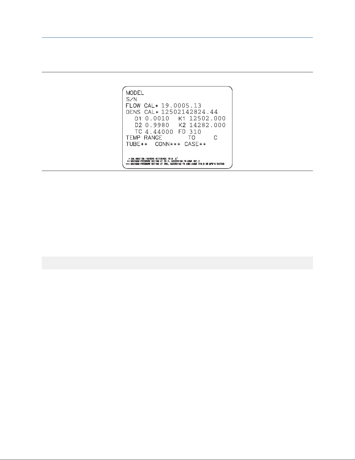
2.8.1 Sample sensor tags
Figure 2-1: Tag on newer curved-tube sensors (all sensors except T-Series)
2.8.2 Flow calibration parameters (FCF, FT)
Two separate values are used to describe flow calibration: a 6-character FCF value and a 4-character FT value.
They are provided on the sensor tag.
Both values contain decimal points. During characterization, these are entered as a single 10-character string.
The 10-character string is called either Flowcal or FCF.
If your sensor tag shows the FCF and the FT values separately and you need to enter a single value,
concatenate the two values to form the single parameter value, retaining both decimal points.
Concatenating FCF and FT
FCF = x.xxxx FT = y.yy Flow calibration parameter: x.xxxxy.yy
2.8.3 Density calibration parameters (D1, D2, K1, K2, FD, DT, TC)
Density calibration parameters are typically on the sensor tag and the calibration certificate.
If your sensor tag does not show a D1 or D2 value:
• For D1, enter the Dens A or D1 value from the calibration certificate. This value is the line-condition
density of the low-density calibration fluid. Micro Motion uses air. If you cannot find a Dens A or D1 value,
enter 0.001 g/cm3.
• For D2, enter the Dens B or D2 value from the calibration certificate. This value is the line-condition density
of the high-density calibration fluid. Micro Motion uses water. If you cannot find a Dens B or D2 value,
enter 0.998 g/cm3 .
If your sensor tag does not show a K1 or K2 value:
• For K1, enter the first five digits of the density calibration factor. In this sample tag, this value is shown as
12500.
• For K2, enter the second five digits of the density calibration factor. In this sample tag, this value is shown
as 14286.
14 Micro Motion 5700 with Ethernet Transmitters
Page 15
Configuration and Use Manual Quick start
MMI-20029769 January 2021
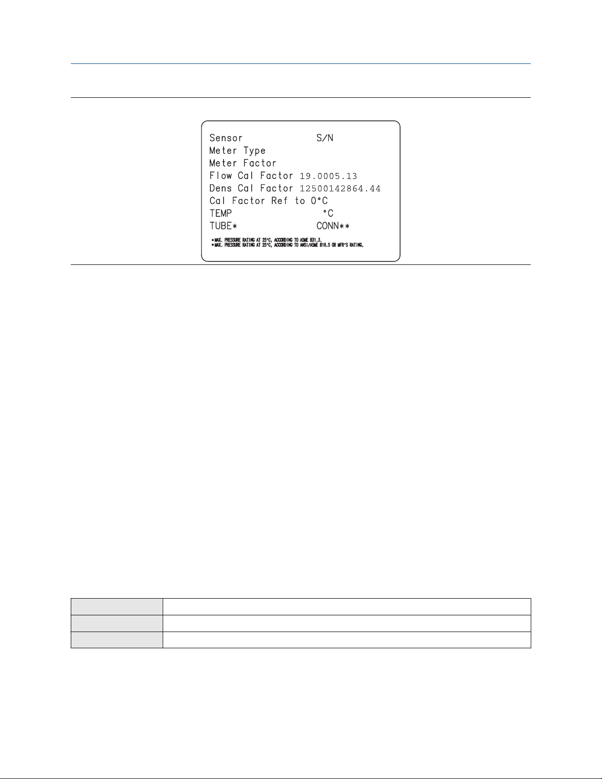
Figure 2-2: K1, K2, and TC values in the density calibration factor
If your sensor does not show an FD value, contact customer service.
If your sensor tag does not show a DT or TC value, enter the last four characters of the density calibration
factor. In the sample tag shown above, the value is shown as 4.44.
Do not confuse the Meter Factor line on the pictured sensor tag with any meter factor settings discussed in
this manual.
2.9 Verify mass flow measurement
Check to see that the mass flow rate reported by the transmitter is accurate. You can use any available
method.
Procedure
• Read the value for Mass Flow Rate on the transmitter display.
• Connect to the transmitter with ProLink III and read the value for Mass Flow Rate in the Process Variables
panel.
Postrequisites
If the reported mass flow rate is not accurate:
• Check the characterization parameters.
• Review the troubleshooting suggestions for flow measurement issues.
2.10 Verify the zero
Display
ProLink III Device Tools → Calibration → Smart Zero Verification and Calibration → Verify Zero
Web browser Service Tools → Verification and Calibration → Meter Zero → Zero Verification
Menu → Service Tools → Verification & Calibration → Meter Zero → Zero Verification
Configuration and Use Manual 15
Page 16

Quick start Configuration and Use Manual
January 2021 MMI-20029769
Verifying the zero helps you determine if the stored zero value is appropriate to your installation, or if a field
zero can improve measurement accuracy.
Important
In most cases, the factory zero is more accurate than the field zero. Do not zero the meter unless one of the
following is true:
• The zero is required by site procedures.
• The stored zero value fails the zero verification procedure.
Do not verify the zero or zero the meter if a high-severity alert is active. Correct the problem, then verify the
zero or zero the meter. You may verify the zero or zero the meter if a low-severity alert is active.
Procedure
1. Prepare the meter:
a) Allow the meter to warm up for at least 20 minutes after applying power.
b) Run the process fluid through the sensor until the sensor temperature reaches the normal
process operating temperature.
c) Stop flow through the sensor by shutting the downstream valve, and then the upstream valve if
available.
d) Verify that the sensor is blocked in, that flow has stopped, and that the sensor is completely full
of process fluid.
2. Start the zero verification procedure, and wait until it completes.
3. If the zero verification procedure fails:
a) Confirm that the sensor is completely blocked in, that flow has stopped, and that the sensor is
completely full of process fluid.
b) Verify that the process fluid is not flashing or condensing, and that it does not contain particles
that can settle out.
c) Repeat the zero verification procedure.
d) If it fails again, zero the meter.
Postrequisites
Restore normal flow through the sensor by opening the valves.
Related information
Zero the meter
16 Micro Motion 5700 with Ethernet Transmitters
Page 17

Configuration and Use Manual Introduction to configuration and commissioning
MMI-20029769 January 2021
3 Introduction to configuration and commissioning
3.1 Security and write protection
The transmitter has several features that can help to protect it against intentional or unintentional access and
configuration changes.
• When locked, the mechanical lock switch on the front of the display prevents any configuration changes
to the transmitter from any local or remote configuration tool. A transmitter without a display does not
have a lock switch.
• When enabled, the software setting Write Protection prevents any configuration changes. The setting
can only be enabled if the transmitter does not have a display.
• If the Universal Service Port (USP) is disabled, the port cannot be used by any service tool to communicate
with or make changes to the transmitter.
• When enabled, Security prevents any configuration changes being made from the display unless the
appropriate password is entered.
3.1.1 Web server security
You can configure this transmitter using web services. There are multiple levels of security built into the
transmitter that you can configure according to your needs and security standards, including:
• Disabling the web servers
• Disallowing firmware upgrades through the Ethernet interface
• Allowing downloads of configuration and historian files, but disallowing file uploads to the transmitter
through the Ethernet interface
• Configuring Transport Layer Security (TLS) on the web server to encrypt all data transmitted between the
web server and the transmitter
• Requiring user authentication and strong passwords to access the web server and the transmitter
• Notifying users through alerts if the default password has not been changed
• Disallowing configuration changes from all interfaces including the Ethernet port using transmitter
security switches, such as the lock switch or write protection
This transmitter:
• Was designed to be implemented in an industrial automation control system (Level 1 and Level 2 of the
Purdue Reference Architecture Model), with defense in depth security controls
(1)
(1)
(1)
• Is not intended to be directly connected to an enterprise or to an internet-facing network without a
compensating control in place
Version 2.0 and higher
(1)
Configuration and Use Manual 17
Page 18
Introduction to configuration and commissioning Configuration and Use Manual
January 2021 MMI-20029769
3.1.2 Universal Service Port security
This transmitter is equipped with a Universal Service Port that works with USB type A connections, including
compatible flash drives. There are multiple levels of security built into the transmitter's service port that you
can configure according to your needs and security standards.
The service port offers the following features that enhance interface security:
• The service port is inaccessible without physical access to the transmitter and requires removal of the
terminal cover
• The service port can be disabled from the transmitter through software
• The transmitter has a non-traditional operating system that is not designed to execute programs or run
scripts
• The display can be password protected to limit access to the USB file menu
• Overall transmitter security switches such as the lock switch or write-protection disallows configuration
changes from all interfaces including the Universal Service Port
This transmitter:
• Was designed to be implemented in an industrial automation control system (Level 1 and Level 2 of the
Purdue Reference Architecture Model), with defense in depth security controls
• Is not intended to be directly connected to an enterprise or to an internet-facing network without a
compensating control in place
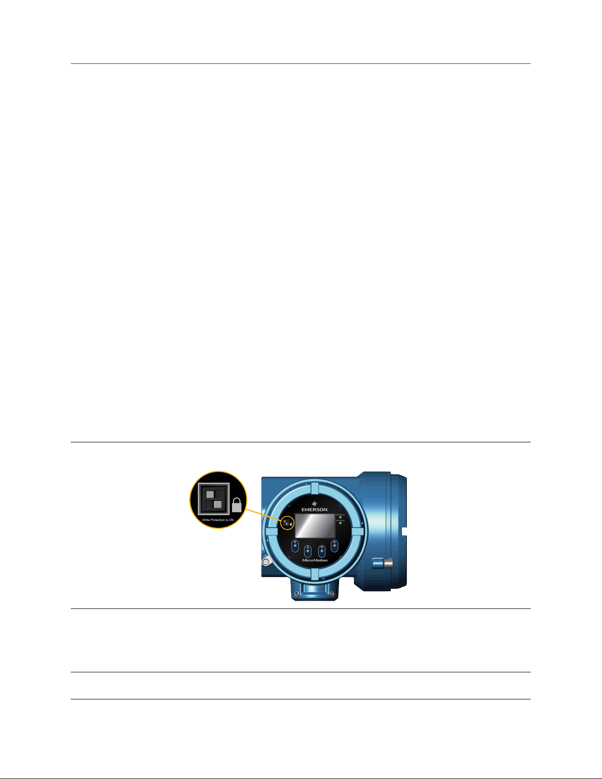
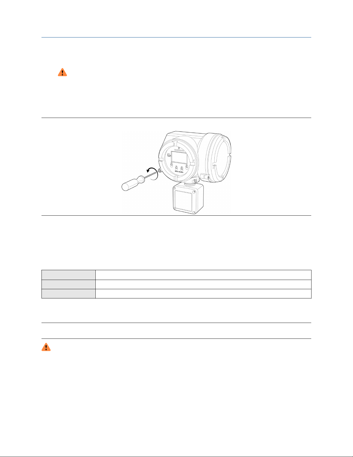
3.1.3 Lock or unlock the transmitter
If the transmitter has a display, a mechanical switch on the display can be used to lock or unlock the
transmitter. When locked, no configuration changes can be made using any configuration tool.
Figure 3-1: Lock switch on transmitter display
You can determine whether you need to lock or unlock the transmitter by looking at the switch.
• If the switch is in the right position, the transmitter is locked.
• If the switch is in the left position, the transmitter is unlocked.
Note
The top switch is reserved for future use.
18 Micro Motion 5700 with Ethernet Transmitters
Page 19
Configuration and Use Manual Introduction to configuration and commissioning
MMI-20029769 January 2021
Procedure
1.
WARNING
If the transmitter is in a hazardous area, do not remove the housing cover while the transmitter is
powered up. Failure to follow these instructions can cause an explosion resulting in injury or death.
If you are in a hazardous area, power down the transmitter.
2. Remove the transmitter housing cover.
Figure 3-2: Removing the transmitter housing cover
3. Using a fine-pointed tool, move the switch to the desired position.
4. Replace the transmitter housing cover.
5. If necessary, power up the transmitter.
3.1.4 Enable or disable the service port
Display
ProLink III Not available
Web browser Not available
The service port is enabled by default, so you can use it for transferring files or connect to it with ProLink III. If
you want to completely prevent it from being used, you can disable it.
Note
Enabling or disabling the service port will not take effect until power has been cycled to the transmitter.
WARNING
Do not use the service port if the transmitter is in a hazardous area because using the service port means
that you must open the transmitter wiring compartment. Opening the wiring compartment in a hazardous
area while the transmitter is powered up can cause an explosion resulting in injury or death.
Menu → Configuration → Security → Service Port
Configuration and Use Manual 19
Page 20

Introduction to configuration and commissioning Configuration and Use Manual
January 2021 MMI-20029769
3.1.5 Enable or disable software write-protection
Display Use the mechanical switch on the display.
ProLink III Device Tools → Configuration → Write-Protection
Web browser Configuration → Security → Write Protection
When enabled, Write-Protection prevents changes to the transmitter configuration. You can perform all
other functions, and you can view the transmitter configuration parameters.
Note
The write protection setting via software methods (such as ProLink III) is available only on transmitters
without a display.
For transmitters with a display, write protection is available only using the lock switch on the display. See Lock
or unlock the transmitter.
Write-protecting the transmitter primarily prevents accidental changes to configuration, not intentional
changes. Any user who can make changes to the configuration can disable write protection.
3.1.6 Configure security for the display
Display Menu → Configuration → Security → Display Security
ProLink III Device Tools → Configuration → Transmitter Display → Display Security
Web browser Not available
When using the display, you can require users to enter a password to do any of the following tasks:
• Enter the main menu
• Change a parameter
• Access alert data through the display
• Start, stop, or reset totalizers or inventories via the context menu
The display password can be the same or different from the totalizer/inventory context menu control
password. If different, the display password is used to reset, start, and stop totalizers or inventories using
Menu → Operations → Totalizers.
20 Micro Motion 5700 with Ethernet Transmitters
Page 21

Configuration and Use Manual Introduction to configuration and commissioning
MMI-20029769 January 2021
Procedure
1. Configure Password Required as desired.
Option Description
At Write When an user chooses an action that leads to a configuration change, they are
prompted to enter the display password.
Enter Menu When the menu is selected from the process variable screen, the display password
will be immediately required if Password Required is set.
Never (default) When a user chooses an action that leads to a configuration change, they are
prompted to activate ⇦⇧⇩⇨. This is designed to protect against accidental changes
to configuration. It is not a security measure.
2. If the At Write or Enter Menu option was selected, enable or disable alert security as desired.
Option Description
Enabled If an alert is active, the alert symbol ⓘ is shown in the upper right corner of the display but
the alert banner is not displayed. If the operator attempts to enter the alert menu, they are
prompted to enter the display password.
Disabled If an alert is active, the alert symbol ⓘ is shown in the upper right corner of the display and
the alert banner is displayed automatically. No password or confirmation is required to
enter the alert menu.
Restriction
You cannot set Password Required to Never and enable alert security.
• If you did not enable Password Required, alert security is disabled and cannot be enabled.
• Alert security is disabled automatically if you set Password Required to Never after:
— Password Required is initially set to either At Write or Enter Menu
— Alert security is enabled
3. If Password Required has been set to At Write or Enter Menu, you will be prompted to enter the
desired password.
• Default: AAAA
• Range: Any four alphanumeric characters
• Password Required must be set to At Write or Enter Menu to enable the totalizer/inventory control
context menu password option.
Important
If you enable Password Required but you do not change the display password, the transmitter will post
a configuration alert.
Configuration and Use Manual 21
Page 22

Introduction to configuration and commissioning Configuration and Use Manual
January 2021 MMI-20029769
4. Configure Main Menu Available as desired.
Option Description
Enabled The local display Menu option from the process variable screen will be accessible.
Disabled The local display Menu option from the process variable screen will not be accessible.
Important
Once Main Menu Available has been disabled, you cannot enable it from the local display. Use another
configuration tool, such as ProLink III, to re-enable main menu access from the local display.
3.2 Work with configuration files
You can save the current transmitter configuration in two forms: a backup file and a replication file. You can
save the configuration to the SD card on your transmitter or to a USB drive.
Tip
You can use a saved configuration file to change the nature of the transmitter quickly. This might be
convenient if the transmitter is used for different applications or different process fluids.
You can load a configuration file to the transmitter's working memory or to the transmitter's SD card. You can
load either a backup file or a replication file.
Backup files
Replication files
Contain all parameters. They are used to restore the current device if required.
The .spare extension is used to identify backup files.
Contain all parameters except the device-specific parameters, e.g., calibration factors or
meter factors. They are used to replicate the transmitter configuration to other devices.
The .xfer extension is used to identify replication files.
3.2.1 Save a configuration file using the display
Prerequisites
If you are planning to use the USB drive, the service port must be enabled. It is enabled by default. However, if
you need to enable it, choose Menu → Configuration → Security and set Service Port to On.
Procedure
• To save the current configuration to the transmitter's SD card as a backup file:
a) Choose Menu → Configuration → Save/Restore Config → Save Config to Memory.
b) Enter the name for this configuration file.
The configuration file is saved to the transmitter's SD card as yourname.spare.
• To save the current configuration to a USB drive, as either a backup file or a replication file:
a)
22 Micro Motion 5700 with Ethernet Transmitters
WARNING
If the transmitter is in a hazardous area, do not remove the housing cover while the transmitter is
powered up. Failure to follow these instructions can cause an explosion resulting in injury or
death.
Page 23

Configuration and Use Manual Introduction to configuration and commissioning
MMI-20029769 January 2021
Open the wiring compartment on the transmitter and insert a USB drive into the service port.
b) Choose Menu → USB Options → Transmitter --> USB Drive → Save Active Config to USB Drive.
c) Choose Backup or Replicate.
d) Enter the name for this configuration file.
The configuration file is saved to the USB drive as yourname.spare or yourname.xfer.
• To copy a configuration file from the transmitter's SD card to the USB drive:
a)
b) Choose Menu → USB Options → Transmitter --> USB Drive → Transfer Config File to USB Drive.
c) Choose Backup or Replicate.
d) Select the file that you want to transfer.
The configuration file is copied to the USB drive, using its existing name.
WARNING
If the transmitter is in a hazardous area, do not remove the housing cover while the transmitter is
powered up. Failure to follow these instructions can cause an explosion resulting in injury or
death.
Open the wiring compartment on the transmitter and insert a USB drive into the service port.
3.2.2 Save a configuration file using ProLink III
Note
When you use ProLink III format for configuration files, you can specify configuration parameters individually
or by groups. Therefore, you can use this format for both backup and replication.
Procedure
• To save the current configuration to the transmitter's SD card:
a) Choose Device Tools → Configuration Transfer → Save Configuration.
b) Select On my 5700 Device Internal Memory and select Next.
c) Select Save.
d) Enter the name for this configuration file.
e) Set the file type.
— To save a backup file, set the file type to Backup.
— To save a replication file, set the file type to Transfer.
f) Select Save.
The configuration file is saved to the transmitter's SD card as yourname.spare or yourname.xfer.
• To save the current configuration to your PC, in 5700 format:
a) Choose Device Tools → Configuration Transfer → Save Configuration.
b) Select On my computer in 5700 device file format and select Next.
Configuration and Use Manual 23
Page 24

Introduction to configuration and commissioning Configuration and Use Manual
January 2021 MMI-20029769
c) Select Save.
d) Browse to the desired location, then enter the name for this configuration file.
e) Set the file type.
— To save a backup file, set the file type to Backup.
— To save a replication file, set the file type to Transfer.
f) Select Save.
The configuration file is saved to the specified location as yourname.spare or yourname.xfer.
• To save the current configuration to your PC, in ProLink III format:
a) Choose Device Tools → Configuration Transfer → Save Configuration.
b) Select On my computer in ProLink III file format and click Next.
c) Select Save.
d) Select the configuration parameters to be included in this file.
— To save a backup file, select all parameters.
— To save a replication file, select all parameters except device-specific parameters.
e) Select Save.
f) Browse to the desired location, then enter the name for this configuration file.
g) Set the file type to ProLink configuration file.
h) Select Start Save.
The configuration file is saved to the specified location as yourname.pcfg.
3.2.3 Load a configuration file using the display
Prerequisites
You must have a backup file or a replication file available for use.
If you are planning to use the USB drive, the service port must be enabled. It is enabled by default. However, if
you need to enable it, choose Menu → Configuration → Security and set Service Port to On.
Procedure
• To load either a backup file or a replication file from the transmitter's SD card:
a) Choose Menu → Configuration → Save/Restore Config → Restore Config from Memory.
b) Select Backup or Replicate.
c) Select the file that you want to load.
The file is loaded to working memory and becomes active immediately.
• To load a either a backup file or a replication file from a USB drive:
24 Micro Motion 5700 with Ethernet Transmitters
Page 25

Configuration and Use Manual Introduction to configuration and commissioning
MMI-20029769 January 2021
a) WARNING
If the transmitter is in a hazardous area, do not remove the housing cover while the transmitter is
powered up. Failure to follow these instructions can cause an explosion resulting in injury or
death.
Open the wiring compartment on the transmitter and insert the USB drive containing the backup
file or replication file into the service port.
b) Choose Menu → USB Options → USB Drive --> Transmitter → Upload Configuration File.
c) Select Backup or Replicate.
d) Select the file that you want to load.
e) Choose Yes or No when prompted to apply the settings.
— Yes: The file is loaded to working memory and becomes active immediately.
— No: The file is loaded to the transmitter's SD card but not to working memory. You can load it
from the SD card to working memory at a later time.
3.2.4 Load a configuration file using ProLink III
You can load a configuration file to the transmitter's working memory. You can load a backup file or a
replication file. Two PC file formats are supported: the 5700 format and the ProLink III format.
Note
When you use ProLink III format for configuration files, you can specify configuration parameters individually
or by groups. Therefore, you can use this format for both backup and replication.
Procedure
• To load a backup file or replication file from the transmitter's SD card:
a) Choose Device Tools → Configuration Transfer → Load Configuration.
b) Select On my 5700 Device Internal Memory and select Next.
c) Select Restore.
d) Set the file type.
— To load a backup file, set the file type to Backup.
— To load a replication file, set the file type to Transfer.
e) Select the file that you want to load and select Load.
The parameters are written to working memory, and the new settings become effectively immediately.
• To load a backup file or replication file in 5700 format from the PC:
a) Choose Device Tools → Configuration Transfer → Load Configuration.
b) Select On my computer in 5700 device file format and select Next.
c) Select Restore.
Configuration and Use Manual 25
Page 26

Introduction to configuration and commissioning Configuration and Use Manual
January 2021 MMI-20029769
d) Set the file type.
— To load a backup file, set the file type to Backup.
— To load a replication file, set the file type to Transfer.
e) Navigate to the file you want to load, and select it.
The parameters are written to working memory, and the new settings become effectively immediately.
• To load a file in ProLink III format from the PC:
a) Choose Device Tools → Configuration Transfer → Load Configuration.
b) Select On my computer in ProLink III file format and select Next.
c) Select the parameters that you want to load.
d) Select Load.
e) Set the file type to Configuration file.
f) Navigate to the file you want to load, and select it.
g) Select Start Load.
The parameters are written to working memory, and the new settings become effectively immediately.
3.2.5 Restore the factory configuration
Display
ProLink III Device Tools → Configuration Transfer → Restore Factory Configuration
Web browser Service Tool → Download Device Files → Factory Config File (download only, no restoration)
A file containing the factory configuration is always saved in the transmitter's internal memory, and is
available for use.
This action is typically used for error recovery or for repurposing a transmitter.
If you restore the factory configuration, the real-time clock, the audit trail, the historian, and other logs are
not reset.
Note
Using a web browser, you can download the factory (.cfg) configuration file and view it with a text editor, but
you must use ProLink III or the display to restore the factory configuration.
Menu → Configuration → Save/Restore Configuration → Restore Config from Memory
3.2.6 Replicate a transmitter configuration
Replicating a transmitter configuration is a fast method to set up similar or identical measurement points.
Procedure
1. Configure a transmitter and verify its operation and performance.
2. Use any available method to save a replication file from that transmitter.
3. Use any available method to load the replication file to another transmitter.
26 Micro Motion 5700 with Ethernet Transmitters
Page 27

Configuration and Use Manual Introduction to configuration and commissioning
MMI-20029769 January 2021
4. At the replicated transmitter, set device-specific parameters and perform device-specific procedures:
a) Set the clock.
b) Set the tag, long tag, Modbus address, and related parameters.
c) Characterize the transmitter.
d) Perform zero validation and take any recommended actions.
e) Perform loop tests and take any recommended actions, including mA Output trim.
f) Use sensor simulation to verify transmitter response.
5. At the replicated transmitter, make any other configuration changes.
6. Follow your standard procedures to ensure that the replicated transmitter is performing as desired.
Configuration and Use Manual 27
Page 28

Introduction to configuration and commissioning Configuration and Use Manual
January 2021 MMI-20029769
28 Micro Motion 5700 with Ethernet Transmitters
Page 29
Configuration and Use Manual Configure process measurement
MMI-20029769 January 2021
4 Configure process measurement
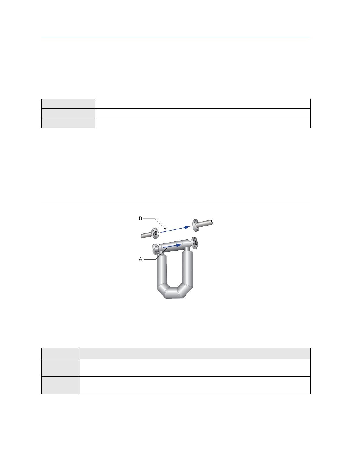
4.1 Configure Sensor Flow Direction Arrow
Display Menu → Configuration → Process Measurement → Flow Variables → Flow Direction
ProLink III Device Tools → Configuration → Process Measurement → Flow → Sensor Direction
Web browser Configuration → Process Measurement → Flow Variables → Sensor Direction
Sensor Flow Direction Arrow is used to accommodate installations in which the Flow arrow on the sensor
does not match the majority of the process flow. This typically happens when the sensor is accidentally
installed backwards.
Sensor Flow Direction Arrow interacts with mA Output Direction, Frequency Output Direction, and
Totalizer Direction to control how flow is reported by the outputs and accumulated by the totalizers and
inventories.
The Sensor Flow Direction Arrow also affects how flow is reported on the transmitter display and via digital
communications. This includes ProLink III, the web browser, and all other user interfaces.
Figure 4-1: Flow arrow on sensor
A. Flow arrow
B. Actual flow direction
Procedure
Set Sensor Flow Direction Arrow as appropriate.
Option
With Arrow The majority of flow through the sensor matches the Flow arrow on the sensor. Actual
Description
forward flow is processed as forward flow.
Against Arrow The majority of flow through the sensor is opposite to the Flow arrow on the sensor. Actual
forward flow is processed as reverse flow.
Configuration and Use Manual 29
Page 30

Configure process measurement Configuration and Use Manual
January 2021 MMI-20029769
Tip
Micro Motion sensors are bidirectional. Measurement accuracy is not affected by actual flow direction or the
setting of Sensor Flow Direction Arrow. Sensor Flow Direction Arrow controls only whether actual flow is
processed as forward flow or reverse flow.
Related information
Configure mA Output Direction
Configure Frequency Output Direction
Configure Discrete Output Source
Configure totalizers and inventories
Effect of Sensor Flow Direction Arrow on digital communications
4.2 Configure mass flow measurement
The mass flow measurement parameters control how mass flow is measured and reported. The mass total
and mass inventory are derived from the mass flow data.
4.2.1 Configure Mass Flow Measurement Unit
Display Menu → Configuration → Process Measurement → Flow Variables → Mass Flow Settings → Units
ProLink III Device Tools → Configuration → Process Measurement → Flow → Mass Flow Rate Unit
Web browser Configuration → Process Measurement → Flow Variables → Mass Flow Rate Unit
Mass Flow Measurement Unit specifies the unit of measure that will be used for the mass flow rate. The
default unit used for mass total and mass inventory is derived from this unit.
Procedure
Set Mass Flow Measurement Unit to the unit you want to use.
Default: g/sec (grams per second)
Tip
If the measurement unit you want to use is not available, you can define a special measurement unit.
Options for Mass Flow Measurement Unit
The transmitter provides a standard set of measurement units for Mass Flow Measurement Unit, plus one
user-defined special measurement unit. Different communications tools may use different labels for the
units.
Label
Unit description
Grams per second gram/s g/sec g/sec
Grams per minute gram/min g/min g/min
Grams per hour gram/h g/hr g/hr
Kilograms per second kg/s kg/sec kg/sec
30 Micro Motion 5700 with Ethernet Transmitters
Display ProLink III Web browser
Page 31

Configuration and Use Manual Configure process measurement
MMI-20029769 January 2021
Label
Unit description
Kilograms per minute kg/min kg/min kg/min
Kilograms per hour kg/h kg/hr kg/hr
Kilograms per day kg/d kg/day kg/day
Metric tons per minute MetTon/min mTon/min mTon/min
Metric tons per hour MetTon/h mTon/hr mTon/hr
Metric tons per day MetTon/d mTon/day mTon/day
Pounds per second lb/s lbs/sec lbs/sec
Pounds per minute lb/min lbs/min lbs/min
Pounds per hour lb/h lbs/hr lbs/hr
Pounds per day lb/d lbs/day lbs/day
Short tons (2000 pounds) per minute STon/min sTon/min sTon/min
Short tons (2000 pounds) per hour STon/h sTon/hr sTon/hr
Short tons (2000 pounds) per day STon/d sTon/day sTon/day
Long tons (2240 pounds) per hour LTon/h lTon/hr lTon/hr
Long tons (2240 pounds) per day LTon/d lTon/day lTon/day
Special unit SPECIAL Special Special
Display ProLink III Web browser
Define a special measurement unit for mass flow
Display
ProLink III Device Tools → Configuration → Process Measurement → Flow → Mass Flow Rate Unit → Special
Web browser Configuration → Process Measurement → Flow Variables → Mass Flow Rate Unit → Special
Procedure
1. Specify Base Mass Unit.
Base Mass Unit is the existing mass unit that the special unit will be based on.
2. Specify Base Time Unit.
Base Time Unit is the existing time unit that the special unit will be based on.
3. Calculate Mass Flow Conversion Factor as follows:
a) x base units = y special units
b) Mass Flow Conversion Factor = x ÷ y
4. Enter Mass Flow Conversion Factor.
The original mass flow rate value is divided by this value.
Menu → Configuration → Process Measurement → Flow Variables → Mass Flow Settings → Units →
SPECIAL
Configuration and Use Manual 31
Page 32

Configure process measurement Configuration and Use Manual
January 2021 MMI-20029769
5. Set Mass Flow Label to the name you want to use for the mass flow unit.
6. Set Mass Total Label to the name you want to use for the mass total and mass inventory unit.
The special measurement unit is stored in the transmitter. You can configure the transmitter to use the
special measurement unit at any time.
Example: Defining a special measurement unit for mass flow
If you want to measure mass flow in ounces per second (oz/sec):
1. Set Base Mass Unit to Pounds (lb).
2. Set Base Time Unit to Seconds (sec).
3. Calculate Mass Flow Conversion Factor:
a. 1 lb/sec = 16 oz/sec
b. Mass Flow Conversion Factor = 1 ÷ 16 = 0.0625
4. Set Mass Flow Conversion Factor to 0.0625.
5. Set Mass Flow Label to oz/sec.
6. Set Mass Total Label to oz.
4.2.2 Configure Flow Damping
Display
ProLink III Device Tools → Configuration → Process Measurement → Flow → Flow Rate Damping
Web browser Configuration → Process Measurement → Flow Variables → Flow Rate Damping
Flow Damping controls the amount of damping that will be applied to the measured mass flow rate. It affects
flow rate process variables that are based on the measured mass flow rate. This includes volume flow rate and
gas standard volume flow rate.
Flow Damping also affects specialized flow rate variables such as temperature-corrected volume flow rate
(API Referral) and net mass flow rate (concentration measurement).
Damping is used to smooth out small, rapid fluctuations in process measurement. The damping value
specifies the time period, in seconds, over which the transmitter will spread changes in the process variable.
At the end of the interval, the internal value of the process variable (the damped value) will reflect 63% of the
change in the actual measured value.
Procedure
Set Flow Damping to the value you want to use.
• Default: 0.64 seconds
Menu → Configuration → Process Measurement → Flow Variables → Flow Damping
• Range: 0 seconds to 60 seconds
Note
If a number greater than 60 is entered, it is automatically changed to 60.
32 Micro Motion 5700 with Ethernet Transmitters
Page 33

Configuration and Use Manual Configure process measurement
MMI-20029769 January 2021
Tip
• A high damping value makes the process variable appear smoother because the reported value changes
slowly.
• A low damping value makes the process variable appear more erratic because the reported value changes
more quickly.
• The combination of a high damping value and rapid, large changes in flow rate can result in increased
measurement error.
• Whenever the damping value is non-zero, the reported measurement will lag the actual measurement
because the reported value is being averaged over time.
• In general, lower damping values are preferable because there is less chance of data loss, and less lag time
between the actual measurement and the reported value.
• The transmitter automatically rounds off any entered damping value to the nearest valid value. Therefore,
the recommended damping value for gas applications should be 3.2 seconds. If you enter 2.56, the
transmitter will round it off to 3.2.
• For filling applications, Micro Motion recommends using the default value of 0.04 seconds.
Effect of flow damping on volume measurement
Flow damping affects volume measurement for liquid volume data. Flow damping also affects volume
measurement for gas standard volume data. The transmitter calculates volume data from the damped mass
flow data.
Interaction between Flow Damping and mA Output Damping
In some circumstances, both Flow Damping and mA Output Damping are applied to the reported mass flow
value.
Flow Damping controls the rate of change in flow process variables. mA Output Damping controls the rate
of change reported via the mA Output. If mA Output Process Variable is set to Mass Flow Rate, and both
Flow Damping and mA Output Damping are set to non-zero values, flow damping is applied first, and the
added damping calculation is applied to the result of the first calculation.
4.2.3 Configure Mass Flow Cutoff
Display
ProLink III Device Tools → Configuration → Process Measurement → Flow → Mass Flow Cutoff
Web browser Configuration → Process Measurement → Flow Variables → Mass Flow Cutoff
Mass Flow Cutoff specifies the lowest mass flow rate that will be reported as measured. All mass flow rates
below this cutoff will be reported as 0.
Menu → Configuration → Process Measurement → Flow Variables → Mass Flow Settings → Low Flow
Cutoff
Procedure
Set Mass Flow Cutoff to the value you want to use.
• Default: A sensor-specific value set at the factory. If your transmitter was ordered without a sensor, the
default may be 0.0.
Configuration and Use Manual 33
Page 34

Configure process measurement Configuration and Use Manual
January 2021 MMI-20029769
• Recommendation: 0.5% of maximum flow rate of the attached sensor. See the sensor specifications.
Important
Do not use your meter for measurement with Mass Flow Cutoff set to 0.0 g/sec. Ensure that Mass Flow
Cutoff is set to the value that is appropriate for your sensor.
Effect of Mass Flow Cutoff on volume measurement
Mass Flow Cutoff does not affect volume measurement. Volume data is calculated from the actual mass data
rather than the reported value.
Volume flow has a separate Volume Flow Cutoff that is not affected by the Mass Flow Cutoff value.
Interaction between Mass Flow Cutoff and mA Output Cutoff
Mass Flow Cutoff defines the lowest mass flow value that the transmitter will report as measured. mA
Output Cutoff defines the lowest flow rate that will be reported via the mA Output. If mA Output Process
Variable is set to Mass Flow Rate, the mass flow rate reported via the mA Output is controlled by the higher of
the two cutoff values.
Mass Flow Cutoff affects all reported values and values used in other transmitter behavior (e.g., events
defined on mass flow).
mA Output Cutoff affects only mass flow values reported via the mA Output.
Example: Cutoff interaction with mA Output Cutoff lower than Mass Flow Cutoff
Configuration:
• mA Output Process Variable: Mass Flow Rate
• Frequency Output Process Variable: Mass Flow Rate
• mA Output Cutoff: 10 g/sec
• Mass Flow Cutoff: 15 g/sec
Result: If the mass flow rate drops below 15 g/sec, mass flow will be reported as 0, and 0 will be used in all
internal processing.
Example: Cutoff interaction with mA Output Cutoff higher than Mass Flow Cutoff
Configuration:
• mA Output Process Variable: Mass Flow Rate
• Frequency Output Process Variable: Mass Flow Rate
• mA Output Cutoff: 15 g/sec
• Mass Flow Cutoff: 10 g/sec
Result:
• If the mass flow rate drops below 15 g/sec but not below 10 g/sec:
— The mA Output will report zero flow.
— The Frequency Output will report the actual flow rate, and the actual flow rate will be used in all
internal processing.
34 Micro Motion 5700 with Ethernet Transmitters
Page 35

Configuration and Use Manual Configure process measurement
MMI-20029769 January 2021
• If the mass flow rate drops below 10 g/sec, both outputs will report zero flow, and 0 will be used in all
internal processing.
4.3 Configure volume flow measurement for liquid
applications
The volume flow measurement parameters control how liquid volume flow is measured and reported. The
volume total and volume inventory are derived from volume flow data.
Restriction
You cannot implement both liquid volume flow and gas standard volume flow at the same time. Choose one
or the other.
4.3.1 Configure Volume Flow Type for liquid applications
Display
ProLink III
Web browser
Volume Flow Type controls whether liquid or gas standard volume flow measurement will be used.
Restriction
Gas standard volume measurement is incompatible with the following applications:
• API Referral
• Concentration measurement
• Advanced Phase Measurement — liquid with gas
For these applications, set Volume Flow Type to Liquid.
Procedure
Set Volume Flow Type to Liquid.
Menu → Configuration → Process Measurement → Flow Variables → Volume Flow Settings → Flow
Type → Liquid
Device Tools → Configuration → Process Measurement → Flow → Volume Flow Type → Liquid Volume
Configuration → Process Measurement → Flow Variables → Volume Flow Type → Liquid Volume
4.3.2 Configure Volume Flow Measurement Unit for liquid
applications
Display
ProLink III Device Tools → Configuration → Process Measurement → Flow → Volume Flow Rate Unit
Web browser Configuration → Process Measurement → Flow Variables → Volume Flow Rate Unit
Menu → Configuration → Process Measurement → Flow Variables → Volume Flow Settings → Units
Volume Flow Measurement Unit specifies the unit of measurement that will be displayed for the volume
flow rate. The unit used for the volume total and volume inventory is based on this unit.
Prerequisites
Before you configure Volume Flow Measurement Unit, be sure that Volume Flow Type is set to Liquid.
Configuration and Use Manual 35
Page 36

Configure process measurement Configuration and Use Manual
January 2021 MMI-20029769
Procedure
Set Volume Flow Measurement Unit to the unit you want to use.
Default: l/sec (liters per second)
Tip
If the measurement unit you want to use is not available, you can define a special measurement unit.
Options for Volume Flow Measurement Unit for liquid applications
The transmitter provides a standard set of measurement units for Volume Flow Measurement Unit, plus one
user-defined measurement unit. Different communications tools may use different labels for the units.
Unit description
Display ProLink III Web browser
Cubic feet per second ft3/s ft3/sec ft3/sec
Cubic feet per minute ft3/min ft3/min ft3/min
Cubic feet per hour ft3/h ft3/hr ft3/hr
Cubic feet per day ft3/d ft3/day ft3/day
Cubic meters per second m3/s m3/sec m3/sec
Cubic meters per minute m3/min m3/min m3/min
Cubic meters per hour m3/h m3/hr m3/hr
Cubic meters per day m3/d m3/day m3/day
U.S. gallons per second gal/s US gal/sec US gal/sec
U.S. gallons per minute gal/m US gal/min US gal/min
U.S. gallons per hour gal/h US gal/hr US gal/hr
U.S. gallons per day gal/d US gal/day US gal/day
Million U.S. gallons per day MMgal/d mil US gal/day mil US gal/day
Liters per second L/s l/sec l/sec
Liters per minute L/min l/min l/min
Label
Liters per hour L/h l/hr l/hr
Million liters per day MML/d mil l/day mil l/day
Imperial gallons per second Impgal/s Imp gal/sec Imp gal/sec
Imperial gallons per minute Impgal/m Imp gal/min Imp gal/min
Imperial gallons per hour Impgal/h Imp gal/hr Imp gal/hr
Imperial gallons per day Impgal/d Imp gal/day Imp gal/day
(1)
(1)
(1)
(1)
bbl/s barrels/sec barrels/sec
bbl/min barrels/min barrels/min
bbl/h barrels/hr barrels/hr
bbl/d barrels/day barrels/day
Barrels per second
Barrels per minute
Barrels per hour
Barrels per day
36 Micro Motion 5700 with Ethernet Transmitters
Page 37

Configuration and Use Manual Configure process measurement
MMI-20029769 January 2021
Unit description
Beer barrels per second
Beer barrels per minute
Beer barrels per hour
Beer barrels per day
Special unit SPECIAL Special Special
(1) Unit based on oil barrels (42 U.S. gallons).
(2) Unit based on U.S. beer barrels (31 U.S. gallons).
(2)
(2)
(2)
(2)
Display ProLink III Web browser
Beer bbl/s Beer barrels/sec Beer barrels/sec
Beer bbl/min Beer barrels/min Beer barrels/min
Beer bbl/h Beer barrels/hr Beer barrels/hr
Beer bbl/d Beer barrels/day Beer barrels/day
Label
Define a special measurement unit for volume flow
Display Menu → Configuration → Process Measurement → Flow Variables → Volume Flow Settings → Units →
ProLink III Device Tools → Configuration → Process Measurement → Flow → Volume Flow Rate Unit → Special
Web browser Configuration → Process Measurement → Flow Variables → Volume Flow Rate Unit → Special
Procedure
1. Specify Base Volume Unit.
Base Volume Unit is the existing volume unit that the special unit will be based on.
SPECIAL
2. Specify Base Time Unit.
Base Time Unit is the existing time unit that the special unit will be based on.
3. Calculate Volume Flow Conversion Factor as follows:
a) x base units = y special units
b) Volume Flow Conversion Factor = x ÷ y
4. Enter Volume Flow Conversion Factor.
The original volume flow rate value is divided by this conversion factor.
5. Set Volume Flow Label to the name you want to use for the volume flow unit.
6. Set Volume Total Label to the name you want to use for the volume total and volume inventory unit.
The special measurement unit is stored in the transmitter. You can configure the transmitter to use the
special measurement unit at any time.
Example: Defining a special measurement unit for volume flow
You want to measure volume flow in pints per second (pints/sec).
1. Set Base Volume Unit to Gallons (gal).
2. Set Base Time Unit to Seconds (sec).
Configuration and Use Manual 37
Page 38

Configure process measurement Configuration and Use Manual
January 2021 MMI-20029769
3. Calculate the conversion factor:
a. 1 gal/sec = 8 pints/sec
b. Volume Flow Conversion Factor = 1 ÷ 8 = 0.1250
4. Set Volume Flow Conversion Factor to 0.1250.
5. Set Volume Flow Label to pints/sec.
6. Set Volume Total Label to pints.
4.3.3 Configure Volume Flow Cutoff
Display Menu → Configuration → Process Measurement → Flow Variables → Volume Flow Settings → Low Flow
ProLink III Device Tools → Configuration → Process Measurement → Flow → Volume Flow Cutoff
Web browser Configuration → Process Measurement → Flow Variables → Volume Flow Cutoff
Volume Flow Cutoff specifies the lowest volume flow rate that will be reported as measured. All volume flow
rates below this cutoff are reported as 0.
Procedure
Set Volume Flow Cutoff to the value you want to use.
• Default: 0.0 l/sec (liters per second)
• Range: 0 l/sec to x l/sec, where x is the sensor’s flow calibration factor, multiplied by 0.0002.
Cutoff
Interaction between Volume Flow Cutoff and mAO Cutoff
Volume Flow Cutoff defines the lowest liquid volume flow value that the transmitter will report as measured.
mAO Cutoff defines the lowest flow rate that will be reported via the mA Output. If mA Output Process
Variable is set to Volume Flow Rate, the volume flow rate reported via the mA Output is controlled by the
higher of the two cutoff values.
Volume Flow Cutoff affects both the volume flow values reported via the outputs and the volume flow values
used in other transmitter behavior (e.g., events defined on the volume flow).
mAO Cutoff affects only flow values reported via the mA Output.
Example: Cutoff interaction with mAO Cutoff lower than Volume Flow Cutoff
Configuration:
• mA Output Process Variable: Volume Flow Rate
• Frequency Output Process Variable: Volume Flow Rate
• AO Cutoff: 10 l/sec
• Volume Flow Cutoff: 15 l/sec
Result: If the volume flow rate drops below 15 l/sec, volume flow will be reported as 0, and 0 will be used in all
internal processing.
38 Micro Motion 5700 with Ethernet Transmitters
Page 39

Configuration and Use Manual Configure process measurement
MMI-20029769 January 2021
Example: Cutoff interaction with mAO Cutoff higher than Volume Flow Cutoff
Configuration:
• mA Output Process Variable: Volume Flow Rate
• Frequency Output Process Variable: Volume Flow Rate
• AO Cutoff: 15 l/sec
• Volume Flow Cutoff: 10 l/sec
Result:
• If the volume flow rate drops below 15 l/sec but not below 10 l/sec:
— The mA Output will report zero flow.
— The Frequency Output will report the actual flow rate, and the actual flow rate will be used in all
internal processing.
• If the volume flow rate drops below 10 l/sec, both outputs will report zero flow, and 0 will be used in all
internal processing.
4.4 Configure Gas Standard Volume (GSV) flow
measurement
The gas standard volume (GSV) flow measurement parameters control how gas standard volume flow is
measured and reported.
Restriction
You cannot implement both liquid volume flow and gas standard volume flow at the same time. Choose one
or the other.
4.4.1 Configure Volume Flow Type for gas applications
Display
ProLink III
Web browser
Volume Flow Type controls whether liquid or gas standard volume flow measurement will be used.
Restriction
Gas standard volume measurement is incompatible with the following applications:
• API Referral
Menu → Configuration → Process Measurement → Flow Variables → Volume Flow Settings → Flow
Type → Gas
Device Tools → Configuration → Process Measurement → Flow → Volume Flow Type → Gas Standard
Volume
Configuration → Process Measurement → Flow Variables → Volume Flow Type → Gas Standard Volume
• Concentration measurement
• Advanced Phase Measurement — liquid with gas
For these applications, set Volume Flow Type to Liquid.
Configuration and Use Manual 39
Page 40

Configure process measurement Configuration and Use Manual
January 2021 MMI-20029769
Procedure
Set Volume Flow Type to Gas.
4.4.2 Configure Standard Gas Density
Display Menu → Configuration → Process Measurement → Flow Variables → Volume Flow Settings → Standard
ProLink III Device Tools → Configuration → Process Measurement → Flow → Standard Density of Gas
Web browser Configuration → Process Measurement → Flow Variables → Standard Density of Gas
Gas Density
Standard Gas Density is the density of your gas at reference temperature and reference pressure. This is
often called standard density or base density. It is used to calculate the GSV flow rate from the mass flow rate.
Procedure
Set Standard Gas Density to the density of your gas at reference temperature and reference pressure.
You can use any reference temperature and reference pressure that you choose. It is not necessary to
configure these values in the transmitter.
Tip
ProLink III provides a guided method that you can use to calculate the standard density of your gas if you do
not know it.
4.4.3 Configure Gas Standard Volume Flow Measurement Unit
Display
ProLink III Device Tools → Configuration → Process Measurement → Flow → Gas Standard Volume Flow Unit
Web browser Configuration → Process Measurement → Flow Variables → Gas Standard Volume Flow Unit
Menu → Configuration → Process Measurement → Flow Variables → Volume Flow Settings → Units
Gas Standard Volume Flow Measurement Unit specifies the unit of measure that will be used for the gas
standard volume (GSV) flow rate. The unit used for gas standard volume total and gas standard volume
inventory is derived from this unit.
Prerequisites
Before you configure Gas Standard Volume Flow Measurement Unit, be sure that Volume Flow Type is set
to Gas Standard Volume.
Procedure
Set Gas Standard Volume Flow Measurement Unit to the unit you want to use.
Default: SCFM (Standard Cubic Feet per Minute)
Tip
If the measurement unit you want to use is not available, you can define a special measurement unit.
40 Micro Motion 5700 with Ethernet Transmitters
Page 41

Configuration and Use Manual Configure process measurement
MMI-20029769 January 2021
Options for Gas Standard Volume Flow Measurement Unit
The transmitter provides a standard set of measurement units for Gas Standard Volume Flow Measurement
Unit, plus one user-defined special measurement unit. Different communications tools may use different
labels for the units.
Unit description
Display ProLink III Web browser
Normal cubic meters per second NCMS Nm3/sec Nm3/sec
Normal cubic meters per minute NCMM Nm3/min Nm3/min
Normal cubic meters per hour NCMH Nm3/hr Nm3/hr
Normal cubic meters per day NCMD Nm3/day Nm3/day
Normal liter per second NLPS NLPS NLPS
Normal liter per minute NLPM NLPM NLPM
Normal liter per hour NLPH NLPH NLPH
Normal liter per day NLPD NLPD NLPD
Standard cubic feet per second SCFS SCFS SCFS
Standard cubic feet per minute SCFM SCFM SCFM
Standard cubic feet per hour SCFH SCFH SCFH
Standard cubic feet per day SCFD SCFD SCFD
Standard cubic meters per second SCMS Sm3/sec Sm3/sec
Standard cubic meters per minute SCMM Sm3/min Sm3/min
Standard cubic meters per hour SCMH Sm3/hr Sm3/hr
Label
Standard cubic meters per day SCMD Sm3/day Sm3/day
Standard liter per second SLPS SLPS SLPS
Standard liter per minute SLPM SLPM SLPM
Standard liter per hour SLPH SLPH SLPH
Standard liter per day SLPD SLPD SLPD
Special measurement unit SPECIAL Special Special
Define a special measurement unit for gas standard volume flow
Display
ProLink III
Web browser
Configuration and Use Manual 41
Menu → Configuration → Process Measurement → Flow Variables → Volume Flow Settings → Units →
SPECIAL
Device Tools → Configuration → Process Measurement → Flow → Gas Standard Volume Flow Unit →
Special
Configuration → Process Measurement → Flow Variables → Gas Standard Volume Flow Unit → Special
Page 42

Configure process measurement Configuration and Use Manual
January 2021 MMI-20029769
A special measurement unit is a user-defined unit of measure that allows you to report process data, totalizer
data, and inventory data in a unit that is not available in the transmitter. A special measurement unit is
calculated from an existing measurement unit using a conversion factor.
Procedure
1. Specify Base Gas Standard Volume Unit.
Base Gas Standard Volume Unit is the existing gas standard volume unit that the special unit will be
based on.
2. Specify Base Time Unit.
Base Time Unit is the existing time unit that the special unit will be based on.
3. Calculate Gas Standard Volume Flow Conversion Factor as follows:
a) x base units = y special units
b) Gas Standard Volume Flow Conversion Factor = x ÷ y
4. Enter the Gas Standard Volume Flow Conversion Factor.
The original gas standard volume flow value is divided by this conversion factor.
5. Set Gas Standard Volume Flow Label to the name you want to use for the gas standard volume flow
unit.
6. Set Gas Standard Volume Total Label to the name you want to use for the gas standard volume total
and gas standard volume inventory unit.
The special measurement unit is stored in the transmitter. You can configure the transmitter to use the
special measurement unit at any time.
Example: Defining a special measurement unit for gas standard volume flow
You want to measure gas standard volume flow in thousands of standard cubic feet per minute.
1. Set Base Gas Standard Volume Unit to SCFM.
2. Set Base Time Unit to minutes (min).
3. Calculate the conversion factor:
a. One thousands of standard cubic feet per minute = 1000 cubic feet per minute
b. Gas Standard Volume Flow Conversion Factor = 1 ÷ 1000 = 0.001
4. Set Gas Standard Volume Flow Conversion Factor to 0.001.
5. Set Gas Standard Volume Flow Label to KSCFM.
6. Set Gas Standard Volume Total Label to KSCF.
4.4.4 Configure Gas Standard Volume Flow Cutoff
Display
ProLink III
Web browser
42 Micro Motion 5700 with Ethernet Transmitters
Menu → Configuration → Process Measurement → Flow Variables → Volume Flow Settings → Low Flow
Cutoff
Device Tools → Configuration → Process Measurement → Flow → Gas Standard Volume Flow Cutoff
Configuration → Process Measurement → Flow Variables → Gas Standard Volume Flow Cutoff
Page 43

Configuration and Use Manual Configure process measurement
MMI-20029769 January 2021
Gas Standard Volume Flow Cutoff specifies the lowest gas standard volume flow rate that will reported as
measured. All gas standard volume flow rates below this cutoff will be reported as 0.
Procedure
Set Gas Standard Volume Flow Cutoff to the value you want to use.
• Default: 0.0
• Range: 0.0 to any positive value
Interaction between Gas Standard Volume Flow Cutoff and mA Output Cutoff
Gas Standard Volume Flow Cutoff defines the lowest Gas Standard Volume flow value that the transmitter
will report as measured. mA Output Cutoff defines the lowest flow rate that will be reported via the mA
Output. If mA Output Process Variable is set to Gas Standard Volume Flow Rate, the volume flow rate
reported via the mA Output is controlled by the higher of the two cutoff values.
Gas Standard Volume Flow Cutoff affects both the gas standard volume flow values reported through
outputs and the gas standard volume flow values used in other transmitter behavior (for example, events
defined on gas standard volume flow).
mA Output Cutoff affects only flow values reported via the mA Output.
Example: Cutoff interaction with mA Output Cutoff lower than Gas Standard Volume Flow Cutoff
Configuration:
• mA Output Process Variable for the primary mA Output: Gas Standard Volume Flow Rate
• Frequency Output Process Variable: Gas Standard Volume Flow Rate
• mA Output Cutoff for the primary mA Output: 10 SLPM (standard liters per minute)
• Gas Standard Volume Flow Cutoff: 15 SLPM
Result: If the gas standard volume flow rate drops below 15 SLPM, the volume flow will be reported as 0, and 0
will be used in all internal processing.
Example: Cutoff interaction with mA Output Cutoff higher than Gas Standard Volume Flow Cutoff
Configuration:
• mA Output Process Variable for the primary mA Output: Gas Standard Volume Flow Rate
• Frequency Output Process Variable: Gas Standard Volume Flow Rate
• mA Output Cutoff for the primary mA Output: 15 SLPM (standard liters per minute)
• Gas Standard Volume Flow Cutoff: 10 SLPM
Result:
• If the gas standard volume flow rate drops below 15 SLPM but not below 10 SLPM:
— The primary mA Output will report zero flow.
— The Frequency Output will report the actual flow rate, and the actual flow rate will be used in all
internal processing.
Configuration and Use Manual 43
Page 44

Configure process measurement Configuration and Use Manual
January 2021 MMI-20029769
• If the gas standard volume flow rate drops below 10 SLPM, both outputs will report zero flow, and 0 will be
used in all internal processing.
4.5 Configure density measurement
The density measurement parameters control how density is measured and reported. Density measurement
is used with mass flow rate measurement to determine liquid volume flow rate.
4.5.1 Configure Density Measurement Unit
Display Menu → Configuration → Process Measurement → Density → Units
ProLink III Device Tools → Configuration → Process Measurement → Density → Density Unit
Web browser Configuration → Process Measurement → Density → Density Unit
Density Measurement Unit controls the measurement units that will be used in density calculations and
reporting.
Restriction
If the API Referral application is enabled, you cannot change the density measurement unit here. The density
measurement unit is controlled by the API table selection.
Procedure
Set Density Measurement Unit to the option you want to use.
Default: g/cm3 (grams per cubic centimeter)
Options for Density Measurement Unit
The transmitter provides a standard set of measurement units for Density Measurement Unit. Different
communications tools may use different labels.
Unit description
Specific gravity
Grams per cubic centimeter g/cm3 g/cm3 g/cm3
Grams per liter g/L g/l g/l
Grams per milliliter g/mL g/ml g/ml
Kilograms per liter kg/L kg/l kg/l
Kilograms per cubic meter kg/m3 kg/m3 kg/m3
Pounds per U.S. gallon lb/gal lbs/USgal lb/USgal
Pounds per cubic foot lb/ft3 lbs/ft3 lb/ft3
Pounds per cubic inch lb/in3 lbs/in3 lb/in3
(1)
Display ProLink III Web browser
SGU SGU SGU
Label
44 Micro Motion 5700 with Ethernet Transmitters
Page 45

Configuration and Use Manual Configure process measurement
MMI-20029769 January 2021
Unit description
Display ProLink III Web browser
Degrees API API API °API
Short ton per cubic yard STon/yd3 sT/yd3 ST/yd3
(1) Non-standard calculation. This value represents line density divided by the density of water at 60 °F (15.6 °C).
Label
4.5.2 Configure Density Damping
Display Menu → Configuration → Process Measurement → Density → Damping
ProLink III Device Tools → Configuration → Process Measurement → Density → Density Damping
Web browser Configuration → Process Measurement → Density → Density Damping
Density Damping controls the amount of damping that will be applied to density data.
Damping is used to smooth out small, rapid fluctuations in process measurement. The damping value
specifies the time period, in seconds, over which the transmitter will spread changes in the process variable.
At the end of the interval, the internal value of the process variable (the damped value) will reflect 63% of the
change in the actual measured value.
Procedure
Set Density Damping to the desired value.
• Default: 1.28 seconds
• Range: 0.0 to 60 seconds
Tip
• A high damping value makes the process variable appear smoother because the reported value changes
slowly.
• A low damping value makes the process variable appear more erratic because the reported value changes
more quickly.
• The combination of a high damping value and rapid, large changes in density can result in increased
measurement error.
• Whenever the damping value is non-zero, the damped value will lag the actual measurement because the
damped value is being averaged over time.
• In general, lower damping values are preferable because there is less chance of data loss, and less lag time
between the actual measurement and the damped value.
• If a number greater than 60 is entered, it is automatically changed to 60.
Configuration and Use Manual 45
Page 46

Configure process measurement Configuration and Use Manual
January 2021 MMI-20029769
Effect of Density Damping on volume measurement
Density Damping affects liquid volume measurement. Liquid volume values are calculated from the damped
density value rather than the measured density value. Density Damping does not affect gas standard volume
measurement.
Interaction between Density Damping and mA Output Damping
When the mA Output is configured to report density, both Density Damping and mA Output Damping are
applied to the reported density value.
Density Damping controls the rate of change in the value of the process variable in transmitter memory. mA
Output Damping controls the rate of change reported via the mA Output.
If mA Output Source is set to Density, and both Density Damping and mA Output Damping are set to nonzero values, density damping is applied first, and the mA Output damping calculation is applied to the result
of the first calculation. This value is reported over the mA Output.
4.5.3 Configure Density Cutoff
Display Menu → Configuration → Process Measurement → Density → Cutoff
ProLink III Device Tools → Configuration → Process Measurement → Density → Density Cutoff
Web browser Configuration → Process Measurement → Density → Density Cutoff
Density Cutoff specifies the lowest density value that will be reported as measured. All density values below
this cutoff will be reported as 0.
Procedure
Set Density Cutoff to the value you want to use.
• Default: 0.2 g/cm
• Range: 0.0 g/cm3 to 0.5 g/cm
3
3
Effect of Density Cutoff on volume measurement
Density Cutoff affects liquid volume measurement. If the density value goes below Density Cutoff, the
volume flow rate is reported as 0.
4.6 Configure temperature measurement
The temperature measurement parameters control how temperature data is processed. Temperature data is
used in several different ways, including temperature compensation, API Referral, and concentration
measurement.
4.6.1 Configure Temperature Measurement Unit
Display
ProLink III Device Tools → Configuration → Process Measurement → Temperature → Temperature Unit
Web browser Configuration → Process Measurement → Temperature → Temperature Unit
46 Micro Motion 5700 with Ethernet Transmitters
Menu → Configuration → Process Measurement → Temperature → Units
Page 47

Configuration and Use Manual Configure process measurement
MMI-20029769 January 2021
Temperature Measurement Unit specifies the unit that will be used for temperature measurement.
Procedure
Set Temperature Measurement Unit to the option you want to use.
Default: °C (Celsius)
Options for Temperature Measurement Unit
The transmitter provides a standard set of units for Temperature Measurement Unit. Different
communications tools may use different labels for the units.
Unit description
Display ProLink III Web browser
Degrees Celsius °C °C °C
Degrees Fahrenheit °F °F °F
Degrees Rankine °R °R °R
Kelvin °K °K °K
Label
4.6.2 Configure Temperature Damping
Display Menu → Configuration → Process Measurement → Temperature → Damping
ProLink III Device Tools → Configuration → Process Measurement → Temperature → Temperature Damping
Web browser Configuration → Process Measurement → Temperature → Temperature Damping
Temperature Damping controls the amount of damping that will be applied to temperature data from the
sensor. Temperature Damping is not applied to external temperature data.
Damping is used to smooth out small, rapid fluctuations in process measurement. The damping value
specifies the time period, in seconds, over which the transmitter will spread changes in the process variable.
At the end of the interval, the internal value of the process variable (the damped value) will reflect 63% of the
change in the actual measured value.
Procedure
Set Temperature Damping to the desired value.
• Default: 4.8 seconds
• Range: 0.0 to 80 seconds
Note
If a number greater than 80 is entered, it is automatically changed to 80.
Tip
• A high damping value makes the process variable appear smoother because the reported value changes
slowly.
• A low damping value makes the process variable appear more erratic because the reported value changes
more quickly.
Configuration and Use Manual 47
Page 48

Configure process measurement Configuration and Use Manual
January 2021 MMI-20029769
• The combination of a high damping value and rapid, large changes in temperature can result in increased
measurement error.
• Whenever the damping value is non-zero, the damped value will lag the actual measurement because the
damped value is being averaged over time.
• In general, lower damping values are preferable because there is less chance of data loss, and less lag time
between the actual measurement and the damped value.
Effect of Temperature Damping on process measurement
Temperature Damping affects all processes and algorithms that use temperature data from the internal
sensor RTD.
Temperature compensation
Temperature compensation adjusts process measurement to compensate for the effect of temperature on
the sensor tubes.
API Referral
Temperature Damping affects API Referral process variables only if the transmitter is configured to use
temperature data from the sensor. If an external temperature value is used for API Referral, Temperature
Damping does not affect API Referral process variables.
Concentration measurement
Temperature Damping affects concentration measurement process variables only if the transmitter is
configured to use temperature data from the sensor. If an external temperature value is used for
concentration measurement, Temperature Damping does not affect concentration measurement process
variables.
4.7 Configure Pressure Measurement Unit
Display
ProLink III
Web browser
Pressure Measurement Unit controls the measurement unit used for pressure. This unit must match the unit
used by the external pressure device.
Pressure data is used for pressure compensation and for API Referral. The device does not measure pressure
directly. You must set up a pressure input.
Procedure
Set Pressure Measurement Unit to the desired unit.
Default: psi
Menu → Configuration → Process Measurement → Pressure → Units
Device Tools → Configuration → Process Measurement → Pressure Compensation → Pressure Unit
Configuration → Process Measurement → Pressure → Pressure Unit
48 Micro Motion 5700 with Ethernet Transmitters
Page 49

Configuration and Use Manual Configure process measurement
MMI-20029769 January 2021
4.7.1 Options for Pressure Measurement Unit
The transmitter provides a standard set of measurement units for Pressure Measurement Unit. Different
communications tools may use different labels for the units. In most applications, set Pressure Measurement
Unit to match the pressure measurement unit used by the remote device.
Unit description
Display ProLink III Web browser
Feet water @ 68 °F ftH2O @68°F Ft Water @ 68°F Ft Water @68°F
Inches water @ 4 °C inH2O @4°C In Water @ 4°C Not applicable
Inches water @ 60 °F inH2O @60°F In Water @ 60°F Not applicable
Inches water @ 68 °F inH2O @68°F In Water @ 68°F In Water @68°F
Millimeters water @ 4 °C mmH2O @4°C mm Water @ 4°C Not applicable
Millimeters water @ 68 °F mmH2O @68°F mm Water @ 68°F mm Water @68°F
Millimeters mercury @ 0 °C mmHg @0°C mm Mercury @ 0°C mm Mercury @0°C
Inches mercury @ 0 °C inHg @0°C In Mercury @ 0°C In Mercury @0°C
Pounds per square inch psi PSI PSI
Bar bar bar bar
Millibar mbar millibar millibar
Grams per square centimeter g/cm2 g/cm2 g/cm2
Kilograms per square centimeter kg/cm2 kg/cm2 kg/cm2
Pascals Pa pascals pascals
Kilopascals kPA Kilopascals Kilopascals
Label
Megapascals mPA Megapascals Not applicable
Torr @ 0 °C torr Torr @ 0°C Torr @0°C
Atmospheres atm atms atms
4.8 Configure Velocity Measurement Unit
Display
ProLink III Device Tools → Configuration → Process Measurement → Velocity → Unit
Web browser Configuration → Process Measurement → Velocity → Unit
Velocity Measurement Unit controls the measurement unit used to report velocity.
Procedure
Set Velocity Measurement Unit to the desired unit.
Default: m/sec
Configuration and Use Manual 49
Menu → Configuration → Process Measurement → Velocity → Units
Page 50

Configure process measurement Configuration and Use Manual
January 2021 MMI-20029769
4.8.1 Options for Velocity Measurement Unit
The transmitter provides a standard set of measurement units for Velocity Measurement Unit. Different
communications tools may use different labels.
Unit description
Display ProLink III Web browser
Feet per minute ft/min ft/min ft/min
Feet per second ft/s ft/sec ft/s
Inches per minute in/min in/min in/min
Inches per second in/s in/sec in/s
Meters per hour m/h m/hr m/h
Meters per second m/s m/sec m/s
Label
50 Micro Motion 5700 with Ethernet Transmitters
Page 51

Configuration and Use Manual Configure process measurement applications
MMI-20029769 January 2021
5 Configure process measurement applications
5.1 Set up the API Referral application
The API Referral application corrects line density to reference temperature and reference pressure according
to American Petroleum Institute (API) standards. The resulting process variable is referred density.
Restriction
The API Referral application is not compatible with the following applications:
• Gas Standard Volume Measurement (GSV)
• Piecewise linearization (PWL)
• Advanced Phase Measurement
• Concentration measurement
5.1.1 Set up the API Referral application using the display
Enable the API Referral application using the display
The API Referral application must be enabled before you can perform any setup. If the API Referral application
was enabled at the factory, you do not need to enable it now.
Prerequisites
The API Referral application must be licensed on your transmitter.
Procedure
1. Choose Menu → Configuration → Process Measurement.
2. Choose Flow Variables → Volume Flow Settings and ensure that Flow Type is set to Liquid.
3. Return to the Process Measurement menu.
4. If the concentration measurement application is displayed in the list, choose Concentration
Measurement and ensure that Enabled/Disabled is set to Disabled.
The concentration measurement application and the API Referral application cannot be enabled
simultaneously.
5. Enable API Referral.
a) Choose Menu → Configuration → Process Measurement → API Referral.
b) Set Enabled/Disabled to Enabled.
Configuration and Use Manual 51
Page 52

Configure process measurement applications Configuration and Use Manual
January 2021 MMI-20029769
Configure API Referral using the display
The API Referral parameters specify the API table, measurement units, and reference values to be used in
referred density calculations.
Prerequisites
You will need API documentation for the API table that you select.
Depending on your API table, you may need to know the thermal expansion coefficient (TEC) for your process
fluid.
You must know the reference temperature and reference pressure that you want to use.
Procedure
1. Choose Menu → Configure → Process Measurement → API Referral.
2. Set API Table to the API table that you want to use to calculate referred density.
Each API table is associated with a specific set of equations. Choose your API table based on your
process fluid and the measurement unit that you want to use for referred density.
Your choice also determines the API table that will be used to calculate the correction factor for volume
(CTPL or CTL).
3. Refer to the API documentation and confirm your table selection.
a) Verify that your process fluid falls within range for line density, line temperature, and line
pressure.
b) Verify that the referred density range of the selected table is adequate for your application.
4. If you chose a C table, enter Thermal Expansion Coefficient (TEC) for your process fluid.
Acceptable limits:
• 230.0 x 10⁻⁶ to 930.0 x 10⁻⁶ per °F
• 414.0 x 10⁻⁶ to 1674.0 x 10-6 per °C
5. If required, set Reference Temperature to the temperature to which density will be corrected in
referred density calculations.
The default reference temperature is determined by the selected API table.
6. If required, set Reference Pressure to the pressure to which density will be corrected in referred
density calculations.
The default reference pressure is determined by the selected API table.
Set up temperature and pressure data for API Referral using the display
The API Referral application uses temperature and, optionally, pressure data in its calculations. You must
decide how to provide this data, then perform the required configuration and setup.
Note
Fixed values for temperature or pressure are not recommended. Using a fixed temperature or pressure value
may produce inaccurate process data.
52 Micro Motion 5700 with Ethernet Transmitters
Page 53

Configuration and Use Manual Configure process measurement applications
MMI-20029769 January 2021
Prerequisites
The pressure measurement must be gauge pressure, not atmospheric pressure.
The pressure device must use the pressure unit that is configured in the transmitter.
If you are using an external temperature device, it must use the temperature unit that is configured in the
transmitter.
Procedure
1. Choose the method to be used to supply temperature data, and perform the required setup.
Method Description Setup
Internal
temperature
Digital
communications
Temperature data from the onboard temperature sensor
(RTD) will be used for all
measurements and
calculations. No external
temperature data will be
available.
A host writes temperature data
to the meter at appropriate
intervals. This data will be
available in addition to the
internal temperature data.
a. Choose Menu → Configuration → Process Measurement
→ Temperature.
b. Set External Temperature to Off.
a. Choose Menu → Configuration → Process Measurement
→ Temperature.
b. Set External Temperature to On.
c. Perform the necessary host programming and
communications setup to write temperature data to the
transmitter at appropriate intervals.
2. Choose the method to be used to supply pressure data, and perform the required setup.
Method
Digital
communications
Description Setup
A host writes pressure data to
the meter at appropriate
intervals.
a. Choose Menu → Configuration → Process Measurement
b. Set External Pressure to On.
c. Perform the necessary host programming and
→ Pressure → External Pressure.
communications setup to write pressure data to the
transmitter at appropriate intervals.
Postrequisites
Choose Menu → Service Tools → Service Data → View Process Variables and verify the values for External
Temperature and External Pressure.
Need help?
If the value is not correct:
• Ensure that the external device and the meter are using the same measurement unit.
• For digital communications, verify that the host has access to the required data.
Configuration and Use Manual 53
Page 54

Configure process measurement applications Configuration and Use Manual
January 2021 MMI-20029769
5.1.2 Set up the API Referral application using ProLink III
Enable the API Referral application using ProLink III
Prerequisites
The API Referral application must be licensed and enabled on your transmitter before you can perform any
setup. If the API Referral application was enabled at the factory, you do not need to enable it now.
Procedure
1. Choose Device Tools → Configuration → Process Measurement → Flow and ensure that Volume
Flow Type is set to Liquid Volume.
2. Choose Device Tools → Configuration → Transmitter Options.
3. If the concentration measurement application is enabled, disable it and select Apply.
The concentration measurement application and the API Referral application cannot be enabled
simultaneously.
4. Enable API Referral and select Apply.
Configure API Referral using ProLink III
The API Referral parameters specify the API table, measurement units, and reference values to be used in
referred density calculations.
Prerequisites
You will need API documentation for the API table that you select.
Depending on your API table, you may need to know the thermal expansion coefficient (TEC) for your process
fluid.
You must know the reference temperature and reference pressure that you want to use.
Procedure
1. Choose Device Tools → Configuration → Process Measurement → API Referral.
2. Specify the API table to use to calculate referred density.
Each API table is associated with a specific set of equations.
a) Set Process Fluid to the API table group that your process fluid belongs to.
API table group
A tables Generalized crude and JP4
B tables Generalized products: Gasoline, jet fuel, aviation fuel, kerosene, heating oils,
Process fluids
fuel oils, diesel, gas oil
C tables Liquids with a constant base density or known thermal expansion coefficient
(TEC). You will be required to enter the TEC for your process fluid.
D tables Lubricating oils
E tables NGL (Natural Gas Liquids) and LPG (Liquid Petroleum Gas)
54 Micro Motion 5700 with Ethernet Transmitters
Page 55

Configuration and Use Manual Configure process measurement applications
MMI-20029769 January 2021
b) Set Referred Density Measurement Unit to the measurement units that you want to use for
referred density.
c) Select Apply.
These parameters uniquely identify the API table to be used to calculate referred density. The selected
API table is displayed, and the meter automatically changes the density unit, temperature unit,
pressure unit, and reference pressure to match the API table.
Your choice also determines the API table that will be used to calculate the correction factor for volume
(CTPL or CTL).
Restriction
Not all combinations are supported by the API Referral application. See the list of API tables in this
manual.
3. Refer to the API documentation and confirm your table selection.
a) Verify that your process fluid falls within range for line density, line temperature, and line
pressure.
b) Verify that the referred density range of the selected table is adequate for your application.
4. If you chose a C table, enter Thermal Expansion Coefficient (TEC) for your process fluid.
Acceptable limits:
• 230.0 x 10⁻⁶ to 930.0 x 10⁻⁶ per °F
• 414.0 x 10⁻⁶ to 1674.0 x 10-6 per °C
5. Set Reference Temperature to the temperature to which density will be corrected in referred density
calculations. If you choose Other, select the temperature measurement unit and enter the reference
temperature.
6. Set Reference Pressure to the pressure to which density will be corrected in referred density
calculations.
Set up temperature and pressure data for API Referral using ProLink III
The API Referral application uses temperature and, optionally, pressure data in its calculations. You must
decide how to provide this data, then perform the required configuration and setup.
Note
Fixed values for temperature or pressure are not recommended. Using a fixed temperature or pressure value
may produce inaccurate process data.
Prerequisites
The pressure measurement must be gauge pressure, not atmospheric pressure.
The pressure device must use the pressure unit that is configured in the transmitter.
If you are using an external temperature device, it must use the temperature unit that is configured in the
transmitter.
Procedure
1. Choose Device Tools → Configuration → Process Measurement → API Referral.
Configuration and Use Manual 55
Page 56

Configure process measurement applications Configuration and Use Manual
January 2021 MMI-20029769
2. Choose the method to be used to supply temperature data, and perform the required setup.
Option Description Setup
Digital
communications
A host writes temperature data
to the meter at appropriate
intervals. This data will be
available in addition to the
internal RTD temperature data.
a. Set Line Temperature Source to Fixed Value or Digital
Communications.
b. Select Apply.
c. Perform the necessary host programming and
communications setup to write temperature data to the
meter at appropriate intervals.
3. Choose the method you will use to supply pressure data, and perform the required setup.
Option Description Setup
Digital
communications
A host writes pressure data to
the meter at appropriate
intervals.
a. Set Pressure Source to Fixed Value or Digital
Communications.
b. Perform the necessary host programming and
communications setup to write pressure data to the meter
at appropriate intervals.
Postrequisites
If you are using external temperature data, verify the external temperature value displayed in the Inputs group
on the ProLink III main window.
The current pressure value is displayed in the External Pressure field. Verify that the value is correct.
Need help?
If the value is not correct:
• Ensure that the external device and the meter are using the same measurement unit.
• For digital communications, verify that the host has access to the required data.
5.1.3 Set up the API Referral application using a web browser
This section guides you through the tasks required to set up and implement the API Referral application.
Enable API Referral using a web browser
The API Referral application must be enabled before you can perform any setup. If the API Referral application
was enabled at the factory, you do not need to enable it now.
Prerequisites
The API Referral application must be licensed on your transmitter.
Procedure
1. Choose Configuration → Transmitter Options and ensure that Volume Flow Type is set to Liquid
Volume.
56 Micro Motion 5700 with Ethernet Transmitters
Page 57

Configuration and Use Manual Configure process measurement applications
MMI-20029769 January 2021
2. If the concentration measurement application is enabled, disable it and select Apply.
The concentration measurement application and the API Referral application cannot be enabled
simultaneously.
3. Enable API Referral and select Apply.
Configure API Referral using a web browser
The API Referral parameters specify the API table, measurement units, and reference values to be used in
referred density calculations.
Prerequisites
You will need API documentation for the API table that you select.
Depending on your API table, you may need to know the thermal expansion coefficient (TEC) for your process
fluid.
You must know the reference temperature and reference pressure that you want to use.
Procedure
1. Choose Configuration → Process Measurement → API Referral.
2. Specify the API table to use to calculate referred density.
Each API table is associated with a specific set of equations.
a) Set Process Fluid to the API table group that belongs to your process fluid.
API table group
A tables Generalized crude and JP4
B tables Generalized products: Gasoline, jet fuel, aviation fuel, kerosene, heating oils,
C tables Liquids with a constant base density or known thermal expansion coefficient
D tables Lubricating oils
E tables NGL (Natural Gas Liquids) and LPG (Liquid Petroleum Gas)
Process fluids
fuel oils, diesel, gas oil
(TEC). You will be required to enter the TEC for your process fluid.
b) Set Referred Density Measurement Unit to the measurement units that you want to use for
referred density.
c) Select Apply.
These parameters uniquely identify the API table to be used to calculate referred density. The selected
API table is displayed, and the meter automatically changes the density unit, temperature unit,
pressure unit, and reference pressure to match the API table.
Your choice also determines the API table that will be used to calculate the correction factor for volume
(CTPL or CTL).
Configuration and Use Manual 57
Page 58

Configure process measurement applications Configuration and Use Manual
January 2021 MMI-20029769
Restriction
Not all combinations are supported by the API Referral application. See the list of API tables in this
manual.
3. Refer to the API documentation and confirm your table selection.
a) Verify that your process fluid falls within range for line density, line temperature, and line
pressure.
b) Verify that the referred density range of the selected table is adequate for your application.
4. If you chose a C table, enter Thermal Expansion Coefficient (TEC) for your process fluid.
Acceptable limits:
• 230.0 x 10⁻⁶ to 930.0 x 10⁻⁶ per °F
• 414.0 x 10⁻⁶ to 1674.0 x 10-6 per °C
5. Set Reference Temperature to the temperature to which density will be corrected in referred density
calculations. If you choose Other, select the temperature measurement unit and enter the reference
temperature.
6. Set Reference Pressure to the pressure to which density will be corrected in referred density
calculations.
Set up temperature and pressure data for API Referral using a web browser
The API Referral application uses temperature and, optionally, pressure data in its calculations. You must
decide how to provide this data, then perform the required configuration and setup.
Note
Fixed values for temperature or pressure are not recommended. Using a fixed temperature or pressure value
may produce inaccurate process data.
Prerequisites
The pressure measurement must be gauge pressure, not atmospheric pressure.
The pressure device must use the pressure unit that is configured in the transmitter.
If you are using an external temperature device, it must use the temperature unit that is configured in the
transmitter.
Procedure
1. Choose Configuration → Process Measurement → API Referral.
2. Choose the method to be used to supply temperature data, and perform the required setup.
58 Micro Motion 5700 with Ethernet Transmitters
Page 59

Configuration and Use Manual Configure process measurement applications
MMI-20029769 January 2021
Option Description Setup
Digital
communications
A host writes temperature data
to the meter at appropriate
intervals. This data will be
available in addition to the
internal RTD temperature data.
a. Set Line Temperature Source to Fixed Value or Digital
Communications.
b. Click Apply.
c. Perform the necessary host programming and
communications setup to write temperature data to the
meter at appropriate intervals.
3. Choose the method you will use to supply pressure data, and perform the required setup.
Option Description Setup
Digital
communications
A host writes pressure data to
the meter at appropriate
intervals.
a. Set Pressure Source to Fixed Value or Digital
Communications.
b. Perform the necessary host programming and
communications setup to write pressure data to the meter
at appropriate intervals.
Postrequisites
If you are using external temperature data, verify the external temperature value displayed in the Inputs group
on the ProLink III main window.
The current pressure value is displayed in the External Pressure field. Verify that the value is correct.
Need help?
If the value is not correct:
• Ensure that the external device and the meter are using the same measurement unit.
• For digital communications, verify that the host has access to the required data.
Configuration and Use Manual 59
Page 60

Configure process measurement applications Configuration and Use Manual
January 2021 MMI-20029769
5.1.4 API tables supported by the API Referral application
The API tables listed here are supported by the API Referral application.
Table 5-1: API tables, process fluids, measurement units, and default reference values
Process fluid
Generalized crude
and JP4
Generalized
products (gasoline,
jet fuel, aviation fuel,
kerosene, heating
oils, fuel oils, diesel,
gas oil)
Liquids with a
constant density
base or known
thermal expansion
coefficient
(5)
API tables
(calculations)
Referred
density
(2)
5A 6A Unit: °API
(1)
CTL or
CTPL
Referred density
(API): unit and
range
(3) (4)
Default
reference
temp
Default
reference
pressure
API standard
60 °F 0 psi (g) API MPMS 11.1
Range: 0 to 100 °API
23A 24A Unit: SGU
60 °F 0 psi (g)
Range: 0.6110 to
1.0760 SGU
53A 54A Unit: kg/m
3
15 °C 0 kPa (g)
Range: 610 to
1075 kg/m³
5B 6B Unit: °API
60 °F 0 psi (g) API MPMS 11.1
Range: 0 to 85 °API
23B 24B Unit: SGU
60 °F 0 psi (g)
Range: 0.6535 to
1.0760 SGU
53B 54B Unit: kg/m
3
15 °C 0 kPa (g)
Range: 653 to
1075 kg/m³
N/A 6C Unit: °API 60 °F 0 psi (g) API MPMS 11.1
N/A 24C Unit: SGU 60 °F 0 psi (g)
N/A 54C Unit: kg/m³ 15 °C 0 kPa (g)
5D 6D Unit: °API
60 °F 0 psi (g) API MPMS 11.1
Range: −10 to
+40 °API
Lubricating oils
23D 24D Unit: SGU
Range: 0.8520 to
60 °F 0 psi (g)
1.1640 SGU
53D 54D Unit: kg/m³
15 °C 0 kPa (g)
Range: 825 to
1164 kg/m³
NGL (natural gas
liquids) and LPG
(liquid petroleum
gas)
23E 24E Unit: SGU 60 °F 0 psi (g) API MPMS 11.2.4
53E 54E Unit: kg/m³ 15 °C 0 psi (g)
59E 60E Unit: kg/m³ 20 °C 0 psi (g)
(1) Each API table represents a specialized equation defined by the American Petroleum Institute for a specific combination
of process fluid, line conditions, and output.
60 Micro Motion 5700 with Ethernet Transmitters
Page 61

Configuration and Use Manual Configure process measurement applications
MMI-20029769 January 2021
(2) Referred density is calculated from line density. You must specify this table, either directly or by selecting the process
fluid and base density measurement unit.
(3) You do not need to specify this table. It is invoked automatically as a result of the previous table selection.
(4) CTL is a correction factor based on online temperature. CTPL is a correction factor based on both line pressure and line
temperature. Calculation of CTL and CTPL for A, B, C, and D table products is in accordance with API MPMS Chapter
11.1. Calculation of CTL and CTPL for E table products is in accordance with API MPMS Chapters 11.2.2, 11.2.4, and
11.2.5.
(5) The Thermal Expansion Coefficient (TEC) replaces the referred density calculation. Use the CTL/CTPL table instead.
5.1.5 Process variables from the API Referral application
The API Referral application calculates several different process variables according to API standards.
CTPL
CTL
Referred density
API volume flow
Batch-weighted
average density
Batch-weighted
average
temperature
API volume total
API volume
inventory
Correction factor based on line temperature and line pressure.
Correction factor based on line temperature at saturation conditions.
The measured density after CTL or CTPL has been applied.
The measured volume flow rate after CTL or CTPL has been applied. Also called
corrected volume flow.
One density value is recorded for each unit of flow (e.g., barrel, liter). The average is
calculated from these values. The average is reset when the API totalizer is reset. Not
available unless a totalizer has been configured with Source set to Corrected Volume
Flow.
One temperature value is recorded for each unit of flow (e.g., barrel, liter). The
average is calculated from these values. The average is reset when the API totalizer is
reset. Not available unless a totalizer has been configured with Source set to
Temperature-Corrected Volume Flow.
The total API volume measured by the transmitter since the last API totalizer reset.
Also called corrected volume total. Not available unless a totalizer has been
configured with Source set to Corrected Volume Flow.
The total API volume measured by the transmitter since the last API inventory reset.
Also called corrected volume inventory. Not available unless an inventory has been
configured with Source set to Corrected Volume Flow.
5.2 Set up concentration measurement
The concentration measurement application calculates concentration from line density and line temperature.
5.2.1 Preparing to set up concentration measurement
The procedure for setting up concentration measurement application depends on how your device was
ordered and how you want to use the application. Review this information before you begin.
Requirements for concentration measurement
To use the concentration measurement application, the following conditions must be met:
• The concentration measurement application must be enabled.
• The API Referral application must be disabled.
Configuration and Use Manual 61
Page 62

Configure process measurement applications Configuration and Use Manual
January 2021 MMI-20029769
• The gas piecewise linearization (PWL) application must be disabled.
• The Advanced Phase Measurement application must be disabled or set for the Liquid with Gas application.
• A concentration matrix must be loaded into one of the six slots on the transmitter.
Tip
In most cases, the concentration matrix that you ordered was loaded at the factory. If it was not, you have
several options for loading a matrix. You can also build a matrix.
• Temperature Source must be configured and set up.
• One matrix must be selected as the active matrix (the matrix used for measurement).
Requirements for matrices
A matrix is the set of coefficients used to convert process data to concentration, plus related parameters. The
matrix can be saved as a file.
The transmitter requires all matrices to be in .matrix format. You can use ProLink III to load matrices in other
formats:
• .edf (used by ProLink II)
• .xml (used by ProLink III)
The transmitter can store matrices in two locations:
• One of the six slots in memory
• The transmitter's SD card
Any matrix in a slot is available for use. In other words, it can be selected as the active matrix and used for
measurement. Matrices on the SD card are not available for use. Matrices must be loaded into a slot before
they can be used for measurement.
All matrices in slots must use the same derived variable. Matrices on the SD card have no requirement for
their derived variables to match.
See the following table for the different ways that you can load matrices.
Table 5-2: Methods to load a matrix file
Action Display ProLink III
Load matrix from USB drive to SD card ✓
Load matrix from computer to slot ✓
Load matrix from SD card to slot ✓ ✓
Requirements for derived variables
A derived variable is the process variable that a concentration matrix measures. All other process variables are
calculated from the derived variable. There are eight possible derived variables. Each matrix is designed for
one specific derived variable.
The transmitter can store up to six matrices in six slots. There are additional matrices on the transmitter's SD
card. All matrices in the six slots must use the same derived variable. If you change the setting of Derived
Variable, all matrices are deleted from the six slots. Any matrices on the transmitter's SD card are not
affected.
62 Micro Motion 5700 with Ethernet Transmitters
Page 63

Configuration and Use Manual Configure process measurement applications
MMI-20029769 January 2021
Tip
Always ensure that Derived Variable is set correctly before loading matrices into slots.
Derived variables and net flow rate
If you want the transmitter to calculate Net Mass Flow Rate, the derived variable must be set to Mass
Concentration (Density). If your matrix is not designed for Mass Concentration (Density), contact customer
support for assistance.
If you want the transmitter to calculate Net Volume Flow Rate, the derived variable must be set to Volume
Concentration (Density). If your matrix is not designed for Volume Concentration (Density), contact customer
support for assistance.
Derived variables based on specific gravity
The following derived variables are based on specific gravity:
• Specific Gravity
• Concentration (Specific Gravity)
• Mass Concentration (Specific Gravity)
• Volume Concentration (Specific Gravity)
If you are using one of these derived variables, two additional parameters can be configured:
• Reference Temperature of Water (default setting: 4 °C)
• Water Density at Reference Temperature(default setting: 999.99988 kg/m³)
These two parameters are used to calculate specific gravity.
You cannot set these parameters from the display. If the default values are not appropriate, you must use
another method to set them.
Optional tasks in setting up concentration measurement
The following tasks are optional:
• Modifying names and labels
• Configuring extrapolation alerts
5.2.2 Set up concentration measurement using the display
This section guides you through most of the tasks related to setting up and implementing the concentration
measurement application.
Restriction
This section does not cover building a concentration matrix. For detailed information on building a matrix, see
the Micro Motion Enhanced Density Application Manual.
Configuration and Use Manual 63
Page 64

Configure process measurement applications Configuration and Use Manual
January 2021 MMI-20029769
Enable concentration measurement using the display
The concentration measurement application must be enabled before you can perform any setup. If the
concentration measurement application was enabled at the factory, you do not need to enable it now.
Prerequisites
The concentration measurement application must be licensed on your transmitter.
Disable the following applications before enabling concentration measurement as concentration
measurement cannot be enabled at the same time:
• Advanced Phase Measurement — gas with liquid
• API Referral
• Piecewise linearization (PWL)
• Gas Standard Volume
Procedure
1. Choose Menu → Configuration → Process Measurement.
2. Choose Flow Variables → Volume Flow Settings and ensure that Flow Type is set to Liquid.
3. Return to the Process Measurement menu.
4. If the API Referral application is displayed in the menu, choose API Referral and ensure that Enabled/
Disabled is set to Disabled.
The concentration measurement application and the API Referral application cannot be enabled
simultaneously.
5. If the Advanced Phase Measurement application is displayed in the menu, choose Advanced Phase
Measurement → Application Setup and ensure that Enabled/Disabled is set to Disabled.
The concentration measurement application, the Advanced Phase Measurement application, net oil,
and gas with liquid cannot be enabled simultaneously.
6. Enable concentration measurement.
a) Choose Menu → Configuration → Process Measurement → Concentration Measurement.
b) Set Enabled/Disabled to Enabled.
Load a concentration matrix from a USB drive using the display
At least one concentration matrix must be loaded into one of the six slots on your transmitter. You can load
up to six matrices into slots. You can also copy matrices to the transmitter's SD card, and load them into slots
at a later time.
Tip
In many cases, concentration matrices were ordered with the device and loaded at the factory. You may not
need to load any matrices.
WARNING
If the transmitter is in a hazardous area, do not remove the housing cover while the transmitter is powered
up. Failure to follow these instructions can cause an explosion resulting in injury or death.
64 Micro Motion 5700 with Ethernet Transmitters
Page 65

Configuration and Use Manual Configure process measurement applications
MMI-20029769 January 2021
Prerequisites
The concentration measurement application must be enabled on your device.
For each concentration matrix that you want to load, you need a file containing the matrix data. The
transmitter's SD card and the ProLink III installation include a set of standard concentration matrices. Other
matrices are available from Micro Motion.
Each concentration matrix file must be in .matrix format.
Tip
• If you have a custom matrix on another device, you can save it to a file, then load it to the current device.
• If you have a matrix file in a different format, you can load it using ProLink III.
The .matrix files must be copied to the root directory of a USB drive.
You must know the derived variable that the matrix is designed to calculate.
Important
• All concentration matrices on your transmitter must use the same derived variable.
• If you change the setting of Derived Variable, all existing concentration matrices will be deleted from the
six slots on the transmitter, but not from the SD card. Set Derived Variable before loading concentration
matrices.
Procedure
1. Choose Menu → Configuration → Process Measurement → Concentration Measurement →
Configure Application and ensure that the setting of Derived Variable matches the derived variable
used by your matrix. If it does not, change it as required and click Apply.
Important
If you change the setting of Derived Variable, all existing concentration matrices will be deleted from
the six slots, but not from the transmitter's SD card. Verify the setting of Derived Variable before
continuing.
2. Load the matrix.
a) Remove the cover from the transmitter's wiring compartment, open the snap flap to access the
service port, and insert the USB drive into the service port.
b) Choose Menu → USB Options → USB Drive --> Transmitter → Upload Configuration File.
c) Set Config File Type to Concentration Measurement Matrix.
d) Select the .matrix file that you want to load, and wait for the transfer to complete.
3. Choose Yes or No when you are asked if you want to apply the settings.
The transmitter has six slots that are used to store concentration matrices. Any one of these can be
used for measurement. The transmitter also has the capability to store multiple concentration matrices
on its SD card. These cannot be used for measurement until they are moved to a slot.
Configuration and Use Manual 65
Page 66

Configure process measurement applications Configuration and Use Manual
January 2021 MMI-20029769
Option Description
Yes The matrix is saved to the SD card, and the loading process continues with loading the
matrix into one of the slots.
No The matrix is saved to the SD card, and the loading process ends. You must load a matrix into
a slot before you can use it for measurement.
4. If you chose Yes, select the slot to load this matrix into, and wait until the load is complete.
You can load the matrix into any empty slot, or you can overwrite an existing matrix.
Postrequisites
If you loaded the matrix into a slot, choose Menu → Configuration → Process Measurement →
Concentration Measurement → Configure Application → Active Matrix and ensure that the matrix is listed.
If you loaded the matrix onto the SD card only, choose Menu → Configuration → Process Measurement →
Concentration Measurement → Load Matrix and ensure that the matrix is listed.
Load a concentration matrix from the SD card using the display
If you have a concentration matrix on the transmitter's SD card, you can load it into one of the six slots on your
transmitter. You cannot use the matrix for measurement until it has been loaded into a slot. You can load up
to six matrices into slots.
Prerequisites
You must have one or more concentration matrices stored on the transmitter's SD card. The standard
matrices are loaded to the SD card at the factory.
You must know the derived variable that the matrix is designed to calculate.
Procedure
1. Choose Menu → Configuration → Process Measurement → Concentration Measurement and ensure
that the setting of Derived Variable matches the derived variable used by your matrix. If it does not,
change it as required and click Apply.
Important
If you change the setting of Derived Variable, all existing concentration matrices will be deleted from
the six slots, but not from the transmitter's SD card. Verify the setting of Derived Variable before
continuing.
2. Choose Menu → Configuration → Process Measurement → Concentration Measurement → Load
Matrix.
The transmitter displays a list of all matrices that are on the SD card.
3. Select the matrix that you want to load.
4. Select the slot that you want to load it into.
You can load the matrix into any empty slot, or you can overwrite an existing matrix.
66 Micro Motion 5700 with Ethernet Transmitters
Page 67

Configuration and Use Manual Configure process measurement applications
MMI-20029769 January 2021
Postrequisites
Choose Menu → Configuration → Process Measurement → Concentration Measurement → Configure
Application → Active Matrix and ensure that the matrix is listed.
Set up temperature data using the display
The concentration measurement application uses line temperature data in its calculations. You must decide
how to provide this data, then perform the required configuration and setup. Temperature data from the onboard temperature sensor (RTD) is always available. Optionally, you can set up an external temperature
device and use external temperature data.
The temperature setup that you establish here will be used for all concentration measurement matrices on
this meter.
Important
Line temperature data is used in several different measurements and calculations. It is possible to use the
internal RTD temperature in some areas and an external temperature in others. The transmitter stores the
internal RTD temperature and the external temperature separately. However, the transmitter stores only one
alternate temperature value, which may be either the external temperature or the configured fixed value.
Accordingly, if you choose a fixed temperature for some uses, and an external temperature for others, the
external temperature will overwrite the fixed value.
Procedure
Choose the method to be used to supply temperature data, and perform the required setup.
Method
Internal
temperature
Digital
communications
Description Setup
Temperature data from the onboard temperature sensor
(RTD) will be used for all
measurements and
calculations. No external
temperature data will be
available.
A host writes temperature data
to the meter at appropriate
intervals. This data will be
available in addition to the
internal temperature data.
a. Choose Menu → Configuration → Process Measurement
b. Set External Temperature to Off.
a. Choose Menu → Configuration → Process Measurement
b. Set External Temperature to On.
c. Perform the necessary host programming and
→ Temperature.
→ Temperature.
communications setup to write temperature data to the
transmitter at appropriate intervals.
Postrequisites
Choose Menu → Service Tools → Service Data → View Process Variables and verify the value for External
Temperature.
Need help?
If the value is not correct:
• Ensure that the external device and the meter are using the same measurement unit.
• For digital communications, verify that the host has access to the required data.
Configuration and Use Manual 67
Page 68

Configure process measurement applications Configuration and Use Manual
January 2021 MMI-20029769
Modify matrix names and labels using the display
For convenience, you can change the name of a concentration matrix and the label used for its measurement
unit. This does not affect measurement.
Procedure
1. Choose Menu → Configuration → Process Measurement → Concentration Measurement →
Configure Matrix.
2. Select the matrix that you want to modify.
3. Set Matrix Name to the name that will be used for this matrix.
4. Set Concentration Unit to the label that will be used for the concentration unit.
If you want to use a custom label, you can use the display to select Special. However, you cannot use
the display to configure the custom label. You must use another tool to change the label from Special
to a user-defined string.
Modify extrapolation alerts using the display
You can enable and disable extrapolation alerts, and set extrapolation alert limits. These parameters control
the behavior of the concentration measurement application but do not affect measurement directly.
Each concentration matrix is built for a specific density range and a specific temperature range. If line density
or line temperature goes outside the range, the transmitter will extrapolate concentration values. However,
extrapolation may affect accuracy. Extrapolation alerts are used to notify the operator that extrapolation is
occurring.
Each concentration matrix has its own extrapolation alert limits.
Procedure
1. Choose Menu → Configuration → Process Measurement → Concentration Measurement →
Configure Matrix.
2. Select the matrix that you want to modify.
3. Set Extrapolation Limit to the point, in percent, at which an extrapolation alert will be posted.
4. Choose Menu → Configuration → Process Measurement → Concentration Measurement →
Configure Application → Extrapolation Alerts.
5. Enable or disable the high and low limit alerts for temperature and density as desired.
Example: Extrapolation alerts in action
If Extrapolation Limit is set to 5%, High Limit (Temp) is enabled, and the active matrix is built for a
temperature range of 40 °F (4.4 °C) to 80 °F (26.7 °C), a high-temperature extrapolation alert will be posted if
line temperature goes above 82 °F (27.8 °C).
68 Micro Motion 5700 with Ethernet Transmitters
Page 69

Configuration and Use Manual Configure process measurement applications
MMI-20029769 January 2021
Select the active concentration matrix using the display
You must select the concentration matrix to be used for measurement. Although the transmitter can store up
to six concentration matrices, only one matrix can be used for measurement at any one time.
Procedure
1. Choose Menu → Configuration → Process Measurement → Concentration Measurement →
Configure Application.
2. Set Active Matrix to the matrix you want to use.
5.2.3 Set up concentration measurement using ProLink III
This section guides you through the tasks required to set up, configure, and implement concentration
measurement.
Enable concentration measurement using ProLink III
The concentration measurement application must be enabled before you can perform any setup. If the
concentration measurement application was enabled at the factory, you do not need to enable it now.
Prerequisites
The concentration measurement application must be licensed on your transmitter.
Disable the following applications before enabling concentration measurement as concentration
measurement cannot be enabled at the same time:
• Advanced Phase Measurement — gas with liquid
• API Referral
• Piecewise linearization (PWL)
• Gas Standard Volume
Procedure
1. Choose Device Tools → Configuration → Process Measurement → Flow and ensure that Volume
Flow Type is set to Liquid Volume.
2. Choose Device Tools → Configuration → Process Measurement → Advance Phase Measurement →
APM Status and ensure that Application Status is set to Disable or Liquid with Gas.
3. Choose Device Tools → Configuration → Transmitter Options.
4. Disable API Referral and set the Advance Phase Measurement application to Disabled or Single Liquid.
5. Disable gas Piecewise Linearization (PWL), and set the Advance Phase Measurement application to
Disabled or Single Liquid.
6. Set Concentration Measurement to Enabled and select Apply.
Load a concentration matrix using ProLink III
At least one concentration matrix must be loaded onto your transmitter. You can load up to six.
Prerequisites
The concentration measurement application must be enabled on your device.
Configuration and Use Manual 69
Page 70

Configure process measurement applications Configuration and Use Manual
January 2021 MMI-20029769
For each concentration matrix that you want to load, you need a file containing the matrix data. The ProLink III
installation includes a set of standard concentration matrices. Other matrices are available from Micro
Motion. The file can be on your computer or in the transmitter's internal memory.
The file must be in one of the formats that ProLink III supports. This includes:
• .xml (ProLink III)
• .matrix (5700)
If you are loading an .xml file, you must know the following information for your matrix:
• The derived variable that the matrix is designed to calculate
• The density unit that the matrix was built with
• The temperature unit that the matrix was built with
If you are loading a .matrix file, you must know the derived variable that the matrix is designed to calculate.
Important
• All concentration matrices on your transmitter must use the same derived variable.
• If you change the setting of Derived Variable, all existing concentration matrices will be deleted from the
six slots on the transmitter, but not from the transmitter's SD card. Set Derived Variable before loading
concentration matrices.
• ProLink III loads matrices directly to one of the transmitter's six slots.
Tip
In many cases, concentration matrices were ordered with the device and loaded at the factory. You may not
need to load any matrices.
Restriction
You cannot use ProLink III to load a matrix to the transmitter's SD card.
Procedure
1. If you are loading an .xml file, choose Device Tools → Configuration → Process Measurement → Line
Density and set Density Unit to the density unit used by your matrix.
Important
When you load a matrix in one of these formats, if the density unit is not correct, concentration data
will be incorrect. The density units must match at the time of loading. You can change the density unit
after the matrix is loaded.
2. If you are loading an .xml file, choose Device Tools → Configuration → Process Measurement → Line
Temperatureand set Temperature Unit to the temperature unit used by your matrix.
Important
When you load a matrix in one of these formats, if the temperature unit is not correct, concentration
data will be incorrect. The temperature units must match at the time of loading. You can change the
temperature unit after the matrix is loaded.
3. Choose Device Tools → Configuration → Process Measurement → Concentration Measurement.
The Concentration Measurement window is displayed. It is organized into steps that allow you to
perform several different setup and configuration tasks. For this task, you will not use all the steps.
70 Micro Motion 5700 with Ethernet Transmitters
Page 71

Configuration and Use Manual Configure process measurement applications
MMI-20029769 January 2021
4. In Step 1, ensure that the setting of Derived Variable matches the derived variable used by your
matrix. If it does not, change it as required and select Apply.
Important
If you change the setting of Derived Variable, all existing concentration matrices will be deleted from
the six slots. Verify the setting of Derived Variable before continuing.
5. Load one or more matrices.
a) In Step 2, set Matrix Being Configured to the location (slot) to which the matrix will be loaded.
b) To load a .xml file from your computer, select Load Matrix from File, navigate to the file, and
load it.
c) To load a .matrix file from your computer, select Load Matrix from My Computer, navigate to
the file, and load it.
d) To load a .matrix file from the transmitter's internal memory, select Load Matrix from 5700
Device Memory, navigate to the file on the transmitter, and load it.
e) Repeat until all required matrices are loaded.
Set reference temperature values for specific gravity using ProLink III
When Derived Variable is set to any option based on specific gravity, you must set the reference temperature
for water, then verify the density of water at the configured reference temperature. These values affect
specific gravity measurement.
This requirement applies to the following derived variables:
• Specific Gravity
• Concentration (Specific Gravity)
• Mass Concentration (Specific Gravity)
• Volume Concentration (Specific Gravity)
Procedure
1. Choose Device Tools → Configuration → Process Measurement → Concentration Measurement.
The Concentration Measurement window is displayed. It is organized into steps that allow you to
perform several different setup and configuration tasks. For this task, you will not use all the steps.
2. Scroll to Step 2, set Matrix Being Configured to the matrix you want to modify, and select Change
Matrix.
3. Scroll to Step 3, then perform the following actions:
a) Set Reference Temperature for Referred Density to the temperature to which line density will
be corrected for use in the specific gravity calculation.
b) Set Reference Temperature for Water to the water temperature that will be used in the specific
gravity calculation.
c) Set Water Density at Reference Temperature to the density of water at the specified reference
temperature.
Configuration and Use Manual 71
Page 72

Configure process measurement applications Configuration and Use Manual
January 2021 MMI-20029769
The transmitter automatically calculates the density of water at the specified temperature. The
new value will be displayed the next time that transmitter memory is read. You can enter a
different value if you prefer.
4. Select Apply at the bottom of Step 3.
Set up temperature data using ProLink III
The concentration measurement application uses line temperature data in its calculations. You must decide
how to provide this data, then perform the required configuration and setup. Temperature data from the onboard temperature sensor (RTD) is always available. Optionally, you can set up an external temperature
device and use external temperature data.
The temperature setup that you establish here will be used for all concentration measurement matrices on
this meter.
Important
Line temperature data is used in several different measurements and calculations. It is possible to use the
internal RTD temperature in some areas and an external temperature in others. The transmitter stores the
internal RTD temperature and the external temperature separately. However, the transmitter stores only one
alternate temperature value, which may be either the external temperature or the configured fixed value.
Accordingly, if you choose a fixed temperature for some uses, and an external temperature for others, the
external temperature will overwrite the fixed value.
Procedure
1. Choose Device Tools → Configuration → Process Measurement → Concentration Measurement.
The Concentration Measurement window is displayed. It is organized into steps that allow you to
perform several different setup and configuration tasks. For this task, you will not use all the steps.
2. Scroll to Step 4.
3. Choose the method to be used to supply temperature data, and perform the required setup.
Option
Internal
temperature
Digital
communications
Description Setup
Temperature data from the onboard temperature sensor
(RTD) will be used for all
measurements and
calculations. No external
temperature data will be
available.
A host writes temperature data
to the meter at appropriate
intervals. This data will be
available in addition to the
internal RTD temperature data.
a. Set Line Temperature Source to Internal.
b. Click Apply.
a. Set Line Temperature Source to Fixed Value or Digital
b. Click Apply.
c. Perform the necessary host programming and
Communications.
communications setup to write temperature data to the
meter at appropriate intervals.
72 Micro Motion 5700 with Ethernet Transmitters
Page 73

Configuration and Use Manual Configure process measurement applications
MMI-20029769 January 2021
Postrequisites
If you are using external temperature data, verify the external temperature value displayed in the Inputs group
on the ProLink III main window.
Need help?
If the value is not correct:
• Ensure that the external device and the meter are using the same measurement unit.
• For digital communications, verify that the host has access to the required data.
Modify matrix names and labels using ProLink III
For convenience, you can change the name of a concentration matrix and the label used for its measurement
unit. This does not affect measurement.
Procedure
1. Choose Device Tools → Configuration → Process Measurement → Concentration Measurement.
The Concentration Measurement window is displayed. It is organized into steps that allow you to
perform several different setup and configuration tasks. For this task, you will not use all the steps.
2. Scroll to Step 2, set Matrix Being Configured to the matrix you want to modify, and click Change
Matrix.
3. Scroll to Step 3, then perform the following actions:
a) Set Concentration Units Label to the label that will be used for the concentration unit.
b) If you set Concentration Units Label to Special, enter the custom label in User-Defined Label.
c) In Matrix Name, enter the name to be used for the matrix.
4. Select Apply at the bottom of Step 3.
Modify extrapolation alerts using ProLink III
You can enable and disable extrapolation alerts, and set extrapolation alert limits. These parameters control
the behavior of the concentration measurement application but do not affect measurement directly.
Each concentration matrix is built for a specific density range and a specific temperature range. If line density
or line temperature goes outside the range, the transmitter will extrapolate concentration values. However,
extrapolation may affect accuracy. Extrapolation alerts are used to notify the operator that extrapolation is
occurring.
Each concentration matrix has its own extrapolation alert limits.
Procedure
1. Choose Device Tools → Configuration → Process Measurement → Concentration Measurement.
The Concentration Measurement window is displayed. It is organized into steps that allow you to
perform several different setup and configuration tasks. For this task, you will not use all the steps.
2. Scroll to Step 2, set Matrix Being Configured to the matrix you want to modify, and click Change
Matrix.
3. Scroll to Step 4.
4. Set Extrapolation Alert Limit to the point, in percent, at which an extrapolation alert will be posted.
Configuration and Use Manual 73
Page 74

Configure process measurement applications Configuration and Use Manual
January 2021 MMI-20029769
5. Enable or disable the high and low limit alerts for temperature and density, as desired, and click Apply.
Example: Extrapolation alerts in action
If Extrapolation Limit is set to 5%, High Limit (Temp) is enabled, and the active matrix is built for a
temperature range of 40 °F (4.4 °C) to 80 °F (26.7 °C), a high-temperature extrapolation alert will be posted if
line temperature goes above 82 °F (27.8 °C).
Select the active concentration matrix using ProLink III
You must select the concentration matrix to be used for measurement. Although the transmitter can store up
to six concentration matrices, only one matrix can be used for measurement at any one time.
Procedure
1. Choose Device Tools → Configuration → Process Measurement → Concentration Measurement.
2. Scroll to Step 2, set Active Matrix to the matrix you want to use and select Change Matrix.
5.2.4 Set up concentration measurement using a web browser
This section guides you through the tasks required to set up, configure, and implement concentration
measurement.
Enable the concentration measurement application using a web browser
The concentration measurement application must be enabled before you can perform any setup. If the
concentration measurement application was enabled at the factory, you do not need to enable it now.
Prerequisites
The concentration measurement application must be licensed on your transmitter.
The API Referral application must not be enabled on your transmitter.
Procedure
1. Choose Configuration → Transmitter Options and ensure that Volume Flow Type is set to Liquid
Volume.
2. Under Permanent Features, set Concentration Measurement to Enabled and click Apply.
Set reference temperature values for specific gravity using a web browser
When Derived Variable is set to any option based on specific gravity, you must set the reference temperature
for water, then verify the density of water at the configured reference temperature. These values affect
specific gravity measurement.
This requirement applies to the following derived variables:
• Specific Gravity
• Concentration (Specific Gravity)
• Mass Concentration (Specific Gravity)
• Volume Concentration (Specific Gravity)
74 Micro Motion 5700 with Ethernet Transmitters
Page 75

Configuration and Use Manual Configure process measurement applications
MMI-20029769 January 2021
Procedure
1. Choose Configuration → Process Measurement → Concentration Measurement.
The Concentration Measurement page is displayed. It is organized into steps that allow you to perform
several different setup and configuration tasks. For this task, you will not use all the steps.
2. Under Step 2, set Matrix Being Configured to the matrix you want to modify, and select Change
Matrix.
3. Under Step 3, perform the following actions:
a) Set Reference Temperature to the temperature to which line density will be corrected for use in
the specific gravity calculation.
b) Set Reference Temperature of Water (Specific Gravity) to the water temperature that will be
used in the specific gravity calculation.
c) Set Water Density at Reference Temperature to the density of water at the specified reference
temperature.
The transmitter automatically calculates the density of water at the specified temperature. The
new value will be displayed the next time that transmitter memory is read. You can enter a
different value if you want to.
4. Select the Apply button at the bottom of Step 3.
Provide temperature data for concentration measurement using a web browser
The concentration measurement application uses line temperature data in its calculations. You must decide
how to provide this data, then perform the required configuration and setup. Temperature data from the onboard temperature sensor (RTD) is always available. Optionally, you can set up an external temperature
device and use external temperature data.
The temperature setup that you establish here will be used for all concentration measurement matrices on
this meter.
Procedure
1. Choose Configuration → Process Measurement → Concentration Measurement.
The Concentration Measurement page is displayed. It is organized into steps that allow you to perform
several different setup and configuration tasks. For this task, you will not use all the steps.
2. Scroll to Step 4.
3. Choose the method to be used to supply temperature data, and perform the required setup.
Option
Internal RTD
temperature data
Description Setup
Temperature data from the onboard temperature sensor
(RTD) is used.
a. Under Line Temperature Data, set Source to RTD.
b. Click Apply.
Configuration and Use Manual 75
Page 76

Configure process measurement applications Configuration and Use Manual
January 2021 MMI-20029769
Option Description Setup
Digital
communications
Postrequisites
If you are using external temperature data, verify the external temperature value displayed on the Process
Monitor page.
Need help?
If the value is not correct:
• Ensure that the external device and the meter are using the same measurement unit.
• For digital communications, verify that the host has access to the required data.
A host writes temperature data
to the meter at appropriate
intervals. This data will be
available in addition to the
internal RTD temperature data.
a. Under Line Temperature Data, set Source to Fixed Value or
Digital Communications.
b. Click Apply.
Modify matrix names and labels using the a web browser
For convenience, you can change the name of a concentration matrix and the label used for its measurement
unit. This does not affect measurement.
Procedure
1. Choose Configuration → Process Measurement → Concentration Measurement.
The Concentration Measurement page is displayed. It is organized into steps that allow you to perform
several different setup and configuration tasks. For this task, you will not use all the steps.
2. Scroll to Step 2, set Matrix Being Configured to the matrix you want to modify, and select Change
Matrix.
3. Scroll to Step 3, then perform the following actions:
a) Set Concentration Units Label to the label that will be used for the concentration unit.
b) If you set Concentration Units Label to Special, enter the custom label in User-Defined Label.
c) In Matrix Name, enter the name to be used for the matrix.
4. Select the Apply button at the bottom of Step 3.
Modify extrapolation alerts for concentration measurement using a web browser
You can enable and disable extrapolation alerts, and set extrapolation alert limits. These parameters control
the behavior of the concentration measurement application but do not affect measurement directly.
Each concentration matrix is built for a specific density range and a specific temperature range. If line density
or line temperature goes outside the range, the transmitter will extrapolate concentration values. However,
extrapolation may affect accuracy. Extrapolation alerts are used to notify the operator that extrapolation is
occurring.
Each concentration matrix has its own extrapolation alert limits.
76 Micro Motion 5700 with Ethernet Transmitters
Page 77

Configuration and Use Manual Configure process measurement applications
MMI-20029769 January 2021
Procedure
1. Choose Configuration → Process Measurement → Concentration Measurement.
The Concentration Measurement window is displayed. It is organized into steps that allow you to
perform several different setup and configuration tasks. For this task, you will not use all the steps.
2. Scroll to Step 2, set Matrix Being Configured to the matrix you want to modify, and click Change
Matrix.
3. Scroll to Step 4.
4. Set Extrapolation Alarm Limit to the point, in percent, at which an extrapolation alert will be posted.
5. Enable or disable the high and low limit alerts for temperature and density, as desired, and click Apply.
Example: Extrapolation alerts in action
If Extrapolation Alarm Limit is set to 5%, High Extrapolation Limit (Temperature) is enabled, and the active
matrix is built for a temperature range of 40 °F (4.4 °C) to 80 °F (26.7 °C), a high-temperature extrapolation
alert will be posted if line temperature goes above 82 °F (27.8 °C).
Select the active concentration matrix using a web browser
You must select the concentration matrix to be used for measurement. Although the transmitter can store up
to six concentration matrices, only one matrix can be used for measurement at any one time.
Procedure
1. Choose Configuration → Process Measurement → Concentration Measurement.
The Concentration Measurement page is displayed. It is organized into steps that allow you to perform
several different setup and configuration tasks. For this task, you will not use all the steps.
2. Scroll to Step 2, set Active Matrix to the matrix you want to use and click Change Matrix.
5.3 Configure the batching application
5.3.1 Configure global batching parameters
Display
ProLink III Device Tools → Configuration → Batcher → Batch Settings
Web browser Configuration → Process Measurement → Batcher → Batch Settings
The global batching parameters apply to all batch presets and all batches.
Procedure
1. Set the flow source to the process variable that will be used to configure and measure the batch.
Note
This field is named Batch Variable in the display.
Menu → Configuration → Process Measurement → Batcher → Global
Options
Mass Flow Rate The batch is measured by mass, using the current mass unit.
Volume Flow Rate The batch is measured by volume, using the current volume unit.
Configuration and Use Manual 77
Description
Page 78

Configure process measurement applications Configuration and Use Manual
January 2021 MMI-20029769
Options Description
API Corrected Vol Flow The batch is measured using the API calculated correction factor.
GSV Flow (only if configured) The batch is measured using the gas standard volume flow rate.
CM Standard Vol Flow (when
licensed and enabled)
CM Net Volume Flow (when
licensed and enabled)
CM Net Mass Flow (when licensed
and enabled)
The batch is measured using the standard volume flow rate at reference
temperature.
The batch is measured using the net volume flow rate at reference
temperature.
The batch is measured using the net mass flow rate.
Example
The current measurement unit for mass flow rate is g/sec. The batch will be configured and measured
in g (grams).
2. Set the maximum target to the largest batch that will be allowed.
• Default: 999999999.0 kg or the equivalent value in the configured measurement unit
• Range: Unlimited
If you try to set the batch target to a larger amount, the transmitter will reject the setting.
3. Set the maximum batch time to the maximum number of seconds that a batch will be allowed to run.
If the batch does not reach its target before this period expires, the batch is halted automatically and
an alert is posted.
• Default: 0 seconds
• Range: 0 to 86,400 seconds (1 day)
If Maximum Fill Time is set to 0, the control is disabled and no maximum time is applied to batches.
5.3.2 Configure batch presets
Display
ProLink III Device Tools → Configuration → Batcher → Preset Configurations
Web browser Configuration → Process Measurement → Batcher → Preset Configurations
A batch preset is a predefined group of batching parameters. You can define and save up to six batch presets.
When you run a batch, you must choose a preset. You can modify the batch target before you run the batch.
All other settings are fixed.
Procedure
1. Select the preset number that you want to configure.
2. Set the preset name to the name to be used for this preset.
The name can be up to eight characters in length. Valid characters include A-Z and 0-9.
3. Set the preset target to the size of the batch.
Menu → Configuration → Process Measurement → Batcher → Presets
78 Micro Motion 5700 with Ethernet Transmitters
Page 79

Configuration and Use Manual Configure process measurement applications
MMI-20029769 January 2021
When the transmitter has measured the specified amount and applied the selected form of AOC, it
closes the valve.
4. Optional: Set the preset end warning point to the point in the batch at which a Modbus coil will be set.
The end warning allows the transmitter to alert the operator to the end of batch. The operator can
prepare for the end of the batch, e.g., by adjusting the flow rate to avoid overflow.
5. Enable or disable the preset as desired.
Note
This field is named Preset Status in the display.
Option Description
Enabled (On) The preset is available for use. You can select it to run a batch.
Disabled (Off) The preset is not available for use. You cannot select it to run a batch. You
can always enable it at a later time.
Preset 1 is always enabled and cannot be disabled.
5.3.3 Configure a DO for valve control
Display Menu → Configuration → Inputs/Outputs
ProLink III Device Tools → Configuration → I/O → Channels
Web browser Configuration → Process Measurement → Inputs/Outputs → Channel C → Discrete Output
The transmitter runs a batch by opening and closing a valve. You can optionally configure a Discrete Output
(DO) to send the open and close commands to the valve.
Prerequisites
• Channel C must be available for valve control.
• The selected channel must be wired to the valve.
• The selected channel and the valve must be powered by a power supply, not by the transmitter.
Procedure
1. Verify the wiring between the selected channel and the valve.
2. Configure the selected channel to operate as a Discrete Output.
a) Set Channel C to operate as a Discrete Output.
b) Set Power Source to External.
3. Configure the channel for valve control.
a) Do one of the following depending on which tool you are using:
Tool
Display 1. Select the Discrete Output to be used for valve control.
Configuration and Use Manual 79
Steps
2. Choose I/O Settings.
Page 80

Configure process measurement applications Configuration and Use Manual
January 2021 MMI-20029769
Tool Steps
ProLink III 1. Navigate to Device Tools → Configuration → I/O → Outputs →
Discrete Output.
2. Select the Discrete Output to be used for valve control.
Web browser Continue to the next step to set the source, polarity, and fault action.
b) Set Source to the batch primary valve.
c) Set Polarity to match the wiring.
The ON state of the Discrete Output must open the valve, and the OFF state must close the
valve.
d) Set Fault Action so that the valve will be closed if a fault occurs.
The appropriate setting is either Upscale or Downscale. The setting to use for your installation
depends on your valve type, your wiring, and your setting for Polarity.
5.3.4 Configure AOC
Display Menu → Configuration → Process Measurement → Batcher → AOC
ProLink III Device Tools → Configuration → Batcher → Batching Options
Web browser Configuration → Process Measurement → Batcher → Batching Options
Automatic Overshoot Compensation (AOC) adjusts the timing of the valve close command to minimize
overshoot. The valve close command is sent before the target is reached, to compensate for the time
required for the valve to close completely. AOC is applied to all presets and all batches.
There are three options for AOC:
Compensation Off
Fixed
Compensation
Value
AOC Algorithm
Procedure
The transmitter sends the close command when the measured batch total reaches
the configured target.
The transmitter sends the close command when the measured batch total equals the
target minus the value configured for Fixed Overshoot Compensation. This value is
configured in the current mass or volume unit, and applies to all presets.
The transmitter compares the actual measured amount of each batch to the batch
target, and determines the adjustment by calibrating itself according to an internal
algorithm. You can choose to stop AOC calibration when you are satisfied with the
result, or you can set up rolling (continuous) AOC calibration.
• To turn compensation off:
Tool
Display Set Compensation Mode to Off.
80 Micro Motion 5700 with Ethernet Transmitters
Steps
Page 81

Configuration and Use Manual Configure process measurement applications
MMI-20029769 January 2021
Tool Steps
ProLink III Set AOC Compensation Mode to Compensation Off.
Web browser Set AOC Compensation Mode to Compensation Off.
• To use the Fixed Compensation Value option:
a) Set the AOC compensation mode to fixed.
Tool Steps
Display Set Compensation Mode to Fixed.
ProLink III Set AOC Compensation Mode to Fixed Compensation Value.
Web browser Set AOC Compensation Mode to Fixed Compensation Value.
b) Set the fixed value or the fixed overshoot compensation to the quantity to be subtracted from the
batch target.
Important
Adjust the fixed value:
— Whenever the process changes (e.g., flow rate, process fluid)
— Whenever you change any configuration parameter that can affect flow measurement (e.g., damping)
• To use the AOC Algorithm option:
Tool
Display Set Compensation Mode to AOC.
ProLink III Set AOC Compensation Mode to AOC Algorithm.
Web browser Set AOC Compensation Mode to AOC Algorithm.
Steps
Configuration and Use Manual 81
Page 82

Configure process measurement applications Configuration and Use Manual
January 2021 MMI-20029769
82 Micro Motion 5700 with Ethernet Transmitters
Page 83

Configuration and Use Manual Configure advanced options for process measurement
MMI-20029769 January 2021
6 Configure advanced options for process measurement
6.1 Configure Response Time
Display Menu → Configuration → Process Measurement → Response Time
ProLink III Device Tools → Configuration → Process Measurement → Response Time
Web browser Configuration → Process Measurement → Response Time
Response Time controls the speed of various internal processes that are involved in retrieving electronic data
from the sensor and converting it to process data.
Response Time affects all process and diagnostic variables.
Restriction
Response Time is configurable only if you are using the enhanced core processor. If you are using the
standard core processor, Response Time is set to Low Filtering and cannot be changed.
Procedure
Set Response Time as desired.
Option
Normal Appropriate for typical applications.
High Filtering Slower response. Appropriate for applications with significant amount of entrained gas or
Low Filtering Fastest response. Appropriate for proving or filling applications.
Service Do not select unless directed by Micro Motion personnel.
Description
process noise.
6.2 Detect and report two-phase flow
Two-phase flow (gas in a liquid process or liquid in a gas process) can cause a variety of process control issues.
The transmitter provides two methods to detect and report or respond to two-phase flow.
6.2.1 Detect two-phase flow using density
Display
ProLink III
Web browser
Menu → Configuration → Process Measurement → Density
Device Tools → Configuration → Process Measurement → Density
Configuration → Process Measurement → Density
Configuration and Use Manual 83
Page 84

Configure advanced options for process measurement Configuration and Use Manual
January 2021 MMI-20029769
The transmitter can use line density data to detect two-phase flow (gas in a liquid process or liquid in a gas
process). The density limits are user-specified. When two-phase flow is detected, an alert is posted.
Procedure
1. Set Two-Phase Flow Low Limit to the lowest density value that is considered normal in your process.
Values below this will cause the transmitter to post a Process Aberration alert.
Tip
Gas entrainment can cause your process density to drop temporarily. To reduce the occurrence of twophase flow alerts that are not significant to your process, set Two-Phase Flow Low Limit slightly below
your expected lowest process density.
You must enter Two-Phase Flow Low Limit in g/cm³, even if you configured another unit for density
measurement.
• Default: 0 g/cm³
• Range: 0 g/cm³ to the sensor limit
2. Set Two-Phase Flow High Limit to the highest density value that is considered normal in your process.
Values above this will cause the transmitter to post a Process Aberration alert.
Tip
To reduce the occurrence of two-phase flow alerts that are not significant to your process, set TwoPhase Flow High Limit slightly above your expected highest process density.
You must enter Two-Phase Flow High Limit in g/cm³, even if you configured another unit for density
measurement.
• Default: 5 g/cm³
• Range: 5 g/cm³ to the sensor limit
3. Set Two-Phase Flow Timeout to the number of seconds that the transmitter will wait for a two-phase
flow condition to clear before posting the alert.
• Default: 0 seconds, meaning that the alert will be posted immediately
• Range: 0 to 60 seconds
6.2.2 Detect two-phase flow using sensor diagnostics
Display
ProLink III
Web browser
Menu → Configuration → Inputs/Outputs → Channel C → I/O Settings → Source
Device Tools → Configuration → I/O → Channels → Channel C → mA Output
Configuration → Inputs/Outputs → Channel C → Channel Type → mA Output
The transmitter always monitors sensor diagnostics and applies a two-phase flow algorithm. You can assign
an mA Output to report the results of this calculation: single-phase flow, moderate two-phase flow, or severe
two-phase flow. Severe two-phase flow can cause the meter to stop functioning.
Procedure
Set mA Output Source to Two-Phase Flow Detection.
84 Micro Motion 5700 with Ethernet Transmitters
Page 85

Configuration and Use Manual Configure advanced options for process measurement
MMI-20029769 January 2021
The signal from the mA Output indicates the current state of the process:
• 12 mA: Single-phase flow
• 16 mA: Moderate two-phase flow
• 20 mA: Severe two-phase flow
6.3 Configure Flow Rate Switch
Display Menu → Configuration → Alert Setup → Enhanced Events → Flow Rate Switch
ProLink III Device Tools → Configuration → I/O → Outputs → Discrete Output → Source → Flow Switch Indication
Web browser Configuration → Inputs/Outputs → Channel C → Discrete Output → Source → Flow Switch Indication
Flow Rate Switch is used to indicate that the flow rate has moved past a user-specified setpoint, in either
direction. The flow rate switch is implemented with a user-configurable hysteresis.
Typically, a Discrete Output is assigned as the flow rate switch indicator. The Discrete Output can be wired to
an external device such as a light or a horn.
Prerequisites
A channel must be configured as a Discrete Output, and the Discrete Output must be available for this use.
Procedure
1. Set Discrete Output Source to Flow Switch, if you have not already done so.
2. Set Flow Switch Variable to the flow variable that you want to use to control the flow rate switch.
3. Set Flow Switch Setpoint to the value at which the flow switch will be triggered (after Hysteresis is
applied).
Depending on the polarity of the Discrete Output:
• If the flow rate is below this value, the Discrete Output is ON.
• If the flow rate is above this value, the Discrete Output is OFF.
4. Set Hysteresis to the percentage of variation above and below the setpoint that will operate as a
deadband.
Hysteresis defines a range around the setpoint within which the flow rate switch will not change.
• Default: 5%
• Range: 0.1% to 10%
Example
If Flow Switch Setpoint = 100 g/sec and Hysteresis = 5%, and the first measured flow rate is above
100 g/sec, the discrete output is OFF. It will remain OFF unless the flow rate drops below 95 g/sec. If
this happens, the discrete output will turn ON, and remain ON until the flow rate rises above 105 g/sec.
At this point it turns OFF and will remain OFF until the flow rate drops below 95 g/sec.
Related information
Configure a Discrete Output
Configuration and Use Manual 85
Page 86

Configure advanced options for process measurement Configuration and Use Manual
January 2021 MMI-20029769
6.4 Configure events
An event occurs when the real-time value of a user-specified process variable moves past a user-defined
setpoint. Events are used to provide notification of process changes or to perform specific transmitter actions
if a process change occurs.
6.4.1 Configure a basic event
Display Not available
ProLink III Device Tools → Configuration → Events → Basic Events
Web browser Not available
A basic event is used to provide notification of process changes. A basic event occurs (is ON) if the real-time
value of a user-specified process variable moves above (HI) or below (LO) a user-defined setpoint. Event status
can be queried via digital communications, and a Discrete Output can be configured to report event status.
You can define up to two basic events.
Procedure
1. Select the event that you want to configure.
2. Assign a process variable to the event.
3. Specify Event Type.
Option
HI x > A
LO x < A
4. Set a value for Setpoint A.
5. Optional: Configure a Discrete Output to switch states in response to the event status.
Related information
Configure Discrete Output Source
Description
The event occurs when the value of the assigned process variable (x) is greater
than the setpoint (Setpoint A), endpoint not included.
The event occurs when the value of the assigned process variable (x) is less than
the setpoint (Setpoint A), endpoint not included.
6.4.2 Configure an enhanced event
Display
ProLink III Device Tools → Configuration → Events → Enhanced Events
Web browser Configuration → Alert Setup → Enhanced Events
An enhanced event is used to provide notification of process changes and, optionally, to perform specific
transmitter actions if the event occurs. An enhanced event occurs (is ON) if the real-time value of a user-
86 Micro Motion 5700 with Ethernet Transmitters
Menu → Configuration → Alert Setup → Enhanced Events
Page 87

Configuration and Use Manual Configure advanced options for process measurement
MMI-20029769 January 2021
specified process variable moves above (HI) or below (LO) a user-defined setpoint, or in range (IN) or out of
range (OUT) with respect to two user-defined setpoints.
You can define up to five enhanced events. For each enhanced event, you can assign one or more actions that
the transmitter will perform if the enhanced event occurs.
Procedure
1. Select the event that you want to configure.
2. Assign a process variable to the event.
3. Specify Event Type.
Option Description
HI x > A
The event occurs when the value of the assigned process variable (x) is greater
than the setpoint (Setpoint A), endpoint not included.
LO x < A
The event occurs when the value of the assigned process variable (x) is less than
the setpoint (Setpoint A), endpoint not included.
IN A ≤ x ≤ B
The event occurs when the value of the assigned process variable (x) is in range,
that is, between Setpoint A and Setpoint B, endpoints included.
OUT x ≤ A or x ≥ B
The event occurs when the value of the assigned process variable (x) is out of
range, that is, less than Setpoint A or greater than Setpoint B, endpoints
included.
4. Set values for the required setpoints.
• For HI and LO events, set Setpoint A.
• For IN and OUT events, set Setpoint A and Setpoint B.
5. Optional: Configure a Discrete Output to switch states in response to the event status.
6. Optional: Specify the action or actions that the transmitter will perform when the event occurs.
Option
Description
Display Menu → Configuration → Alert Setup →
Enhanced Events, select any enhanced event,
and choose Assign Actions
ProLink III Device Tools → Configuration → I/O → Inputs →
Action Assignment
Related information
Configure Discrete Output Source
Configuration and Use Manual 87
Page 88

Configure advanced options for process measurement Configuration and Use Manual
January 2021 MMI-20029769
Options for Enhanced Event Action
Action Label
Display PLIII
Standard
Start sensor zero Start Zero Calibration Start Sensor Zero
Totalizers
Start/stop all totalizers and inventories Start/stop all totalizers Start or Stop All Totalizers
Reset totalizer X Reset Total X Totalizer X
Reset all totalizers and inventories Reset All Totals Reset All Totals
Concentration measurement
Increment CM matrix Increment Matrix Increment ED Curve
Meter verification
Start meter verification test Start SMV Start Meter Verification
Batching
Begin batch Begin Batch Begin Batch
End batch End Batch End Batch
Resume batch Resume Batch Resume Batch
Increment batch preset Increment Preset Increment Batch Preset
Inhibit batch totalizer Inhibit Totalizer Inhibit Batch Totalizing
Inhibit batch Inhibit Batch Inhibit Batch Start
Inhibit batch flow Inhibit Flow Allow Batch End with Flow
6.5 Configure totalizers and inventories
Display
ProLink III Device Tools → Totalizer Control → Totalizers
Web browser Configuration → Totalizers/Inventories
The transmitter provides seven configurable totalizers and seven configurable inventories. Each totalizer and
each inventory can be configured independently.
Totalizers track the process since the last totalizer reset. Inventories track the process since the last inventory
reset. Inventories are typically used to track the process across totalizer resets.
Menu → Configuration → Process Measurement → Totalizers & Inventories
Tip
The default configurations cover the most typical uses of totalizers and inventories. You may not need to
change any configurations.
88 Micro Motion 5700 with Ethernet Transmitters
Page 89

Configuration and Use Manual Configure advanced options for process measurement
MMI-20029769 January 2021
Prerequisites
Before configuring the totalizers and inventories, ensure that the process variables you plan to track are
available on the transmitter.
Procedure
1. Select the totalizer or inventory that you want to configure.
2. Set Totalizer Source or Inventory Source to the process variable that the totalizer or inventory will
track.
Option Description
Mass flow The totalizer or inventory will track Mass Flow Rate and calculate total
mass since the last reset.
Volume flow The totalizer or inventory will track Volume Flow Rate and calculate total
volume since the last reset.
Gas standard volume
flow
Temperature-corrected
volume flow
The totalizer or inventory will track Gas Standard Volume Flow Rate and
calculate total volume since the last reset.
The totalizer or inventory will track Temperature-Corrected Volume Flow
Rate and calculate total volume since the last reset.
Standard volume flow The totalizer or inventory will track Standard Volume Flow Rate and
calculate total volume since the last reset.
Net mass flow The totalizer or inventory will track Net Mass Flow Rate and calculate total
mass since the last reset.
Net volume flow The totalizer or inventory will track Net Volume Flow Rate and calculate
total volume since the last reset.
Note
The totalizer/inventory value will not automatically be reset when the source is changed. The user must
manually reset the totalizer/inventory.
Tip
If you are using the API Referral application and you want to measure batch-weighted average density
or batch-weighted average temperature, you must have a totalizer configured to measure
temperature-corrected volume flow.
3. Set Totalizer Direction to specify how the totalizer or inventory will respond to forward or reverse flow.
Option
Flow direction Totalizer and inventory behavior
Forward Only Forward Totals increment
Reverse Totals do not change
Reverse Only Forward Totals do not change
Reverse Totals increment
Bidirectional Forward Totals increment
Reverse Totals decrement
Configuration and Use Manual 89
Page 90

Configure advanced options for process measurement Configuration and Use Manual
January 2021 MMI-20029769
Option Flow direction Totalizer and inventory behavior
Absolute Value Forward Totals increment
Reverse Totals increment
Important
Actual flow direction interacts with Sensor Flow Direction Arrow to determine the flow direction that
the transmitter uses in processing. See the following table.
Table 6-1: Interaction between actual flow direction and Sensor Flow Direction Arrow
Actual flow direction
Forward (same direction as Flow
arrow on sensor)
Reverse (opposite from Flow arrow
on sensor)
Setting of Sensor Flow Direction
Arrow
With Arrow Forward
Against Arrow Reverse
With Arrow Reverse
Against Arrow Forward
Flow direction sent to outputs
and totalizers
4. Optional: Set User Name to the name you want to use for the inventory or totalizer.
User Name can have a maximum of 16 characters.
The transmitter automatically generates a name for each totalizer and inventory, based on its source,
direction, and type.
Example
• Totalizer Source=Mass Flow
• Totalizer Direction=Forward Only
• Totalizer name=Mass Fwd Total
Example
• Inventory Source=Gas Standard Volume Flow
• Inventory Direction=Bidirectional
• Inventory name = GSV Bidir Inv
The specified name is used on the transmitter display and on all interfaces that support it. If User Name
contains only spaces, the transmitter-generated name is used. Not all interfaces support totalizer and
inventory names.
Example: Checking for backflow
You suspect that there is a significant amount of backflow through the sensor. To collect data, configure two
totalizers as follows:
• Source=Mass Flow, Direction=Forward Only
• Source=Mass Flow, Direction=Reverse Only
90 Micro Motion 5700 with Ethernet Transmitters
Page 91

Configuration and Use Manual Configure advanced options for process measurement
MMI-20029769 January 2021
Reset both totalizers, allow them to run for an appropriate period, then look at the amount of reverse flow as
a percentage of forward flow.
Example: Tracking three different process fluids
Three tanks are connected to a loading dock through a single meter. Each tank contains a different process
fluid. You want to track each process fluid separately.
1. Set up three totalizers, one for each tank.
2. Name the totalizers Tank 1, Tank 2, and Tank 3.
3. Configure each totalizer as required for the corresponding process fluid.
4. Stop and reset all three totalizers to ensure that the beginning values are 0.
5. When loading from a tank, start the corresponding totalizer, and stop it when the load is finished.
6.5.1 Default settings for totalizers and inventories
Totalizer or
inventory
1 Mass flow Forward Only Mass Fwd Total
2 Volume flow Forward Only Volume Fwd Total
3 Temperature-corrected volume
4 Gas standard volume flow Forward Only GSV Fwd Total
5 Standard volume flow Forward Only Standard Vol Fwd Total
6 Net mass flow Forward Only Net Mass Fwd Total
7 Net volume flow Forward Only Net Vol Fwd Total
Source (process variable
assignment
flow
Direction Name of totalizer
Name of inventory
Mass Fwd Inv
Volume Fwd Inv
Forward Only API Volume Fwd Total
API Volume Fwd Inv
GSV Fwd Inv
Standard Vol Fwd Inv
Net Mass Fwd Inv
Net Vol Fwd Inv
6.6 Configure logging for totalizers and inventories
Display
ProLink III Device Tools → Configuration → Totalizer Log
Web browser Configuration → Totalizers/Inventories → Totalizer Log
Menu → Configuration → Totalizer Log
Configuration and Use Manual 91
Page 92

Configure advanced options for process measurement Configuration and Use Manual
January 2021 MMI-20029769
The transmitter can write the current value of four totalizers or inventories to a log, at user-specified intervals.
You can generate a log file from this data for viewing and analysis.
Procedure
1. Specify the date on which totalizer logging will begin.
You must specify a future date. If you try to specify the current date, the transmitter will reject the
setting.
2. Specify the time at which totalizer logging will begin.
3. Specify the number of hours between records.
4. Select up to four totalizers or inventories to be logged.
6.7 Configure Process Variable Fault Action
Display Menu → Configuration → Alert Setup → Output Fault Actions
ProLink III Device Tools → Configuration → Fault Processing
Web browser Configuration → Alert Setup → Output Fault Actions
Process Variable Fault Action specifies the values that will be reported via the display and digital
communications if the device encounters a fault condition. The values are also sent to the outputs for
processing against their configured fault actions.
Procedure
Set Process Variable Fault Action as desired.
Default: None
Restriction
If you set Process Variable Fault Action to NAN, you cannot set mA Output Fault Action or Frequency
Output Fault Action to None. If you try to do this, the transmitter will not accept the configuration.
Important
• If you want the mA Output to continue reporting process data during fault conditions, you must set both
Process Variable Fault Action and mA Output Fault Action to None. If mA Output Fault Action is set to
None and Process Variable Fault Action is set to any other option, the mA Output will produce the signal
associated with the selection.
• If you want the Frequency Output to continue reporting process data during fault conditions, you must set
both Process Variable Fault Action and Frequency Output Fault Action to None. If Frequency Output
Fault Action is set to None and Process Variable Fault Action is set to any other option, the Frequency
Output will produce the signal associated with the selection.
92 Micro Motion 5700 with Ethernet Transmitters
Page 93

Configuration and Use Manual Configure advanced options for process measurement
MMI-20029769 January 2021
6.7.1 Options for Process Variable Fault Action
Label
Display ProLink III Web browser
Upscale Upscale Upscale • Process variable values indicate that the
Downscale Downscale Downscale • Process variable values indicate that the
Zero Zero Zero • Flow rate variables go to the value that
Description
value is greater than the upper sensor limit.
• Totalizers stop incrementing.
value is lower than the lower sensor limit.
• Totalizers stop incrementing.
represents a flow rate of 0 (zero).
• Density is reported as 0.
• Temperature is reported as 0 °C , or the
equivalent if other units are used (e.g.,
32 °F .
• Drive gain is reported as measured.
• Totalizers stop incrementing.
Not-a-Number (NAN) Not a Number Not a Number • Process variables are reported as IEEE
NAN.
• Drive gain is reported as measured.
• Modbus scaled integers are reported as
Max Int.
• Totalizers stop incrementing.
Flow to Zero Flow to Zero Flow to Zero • Flow rates are reported as 0.
• Other process variables are reported as
measured.
• Totalizers stop incrementing.
None (default) None None (default) • All process variables are reported as
measured.
• Totalizers increment if they are running.
Configuration and Use Manual 93
Page 94

Configure advanced options for process measurement Configuration and Use Manual
January 2021 MMI-20029769
6.7.2 Interaction between Process Variable Fault Action and other fault actions
The setting of Process Variable Fault Action affects the operation of the mA Outputs, Frequency Outputs,
and Discrete Outputs if the corresponding output fault actions are set to None.
Interaction between Process Variable Fault Action and mA Output Fault Action
If mA Output Fault Action is set to None, the mA Output signal depends on the setting of Process Variable
Fault Action.
If the device detects a fault condition:
1. Process Variable Fault Action is evaluated and applied.
2. mA Output Fault Action is evaluated.
• If it is set to None, the output reports the value associated with the setting of Process Variable
Fault Action.
• If it is set to any other option, the output performs the specified fault action.
If you want the mA Output to continue to report process data during fault conditions, you must set both mA
Output Fault Action and Process Variable Fault Action to None.
Interaction between Process Variable Fault Action and Frequency Output Fault Action
If Frequency Output Fault Action is set to None, the Frequency Output signal depends on the setting of
Process Variable Fault Action.
If the device detects a fault condition:
1. Process Variable Fault Action is evaluated and applied.
2. Frequency Output Fault Action is evaluated.
• If it is set to None, the output reports the value associated with the setting of Process Variable
Fault Action.
• If it is set to any other option, the output performs the specified fault action.
If you want the Frequency Output to continue to report process data during fault conditions, you must set
both Frequency Output Fault Action and Process Variable Fault Action to None.
Interaction between Process Variable Fault Action and Discrete Output Fault Action
If Discrete Output Fault Action is set to None and Discrete Output Source is set to Flow Rate Switch, the
Discrete Output state during a fault depends on the setting of Process Variable Fault Action.
If the device detects a fault condition:
1. Process Variable Fault Action is evaluated and applied.
2. Discrete Output Fault Action is evaluated.
• If it is set to None, and Discrete Output Source is set to Flow Rate Switch, the Discrete Output will
use the value determined by the current setting of Process Variable Fault Action to determine if a
flow rate switch has occurred.
94 Micro Motion 5700 with Ethernet Transmitters
Page 95

Configuration and Use Manual Configure advanced options for process measurement
MMI-20029769 January 2021
• If Discrete Output Source is set to any other option, the setting of Process Variable Fault Action is
irrelevant to the behavior of the Discrete Output during fault conditions. The Discrete Output is set
to the specified fault action.
If you want the Discrete Output to report a flow rate switch appropriately during fault conditions, you must
set both Discrete Output Fault Action and Process Variable Fault Action to None.
Related information
Configure mA Output Fault Action
Configure Frequency Output Fault Action
Configure Discrete Output Fault Action
Configuration and Use Manual 95
Page 96

Configure advanced options for process measurement Configuration and Use Manual
January 2021 MMI-20029769
96 Micro Motion 5700 with Ethernet Transmitters
Page 97

Configuration and Use Manual Configure device options and preferences
MMI-20029769 January 2021
7 Configure device options and preferences
7.1 Configure the transmitter display
You can control the language used on the display, the process variables shown on the display, and a variety of
display behaviors.
7.1.1 Configure the language used on the display
Display Menu → Configuration → Display Settings → Language
ProLink III Device Tools → Configuration → Local Display Settings → Transmitter Display → General → Language
Web browser Configuration → Transmitter Display → General → Language
Language controls the language that the display uses for process data, menus, and information.
The languages available depend on your transmitter model and version.
Procedure
Set Language to the desired language.
7.1.2 Configure the process variables shown on the display
Display
ProLink III Device Tools → Configuration → Transmitter Display → Display Variables
Web browser Configuration → Transmitter Display → Display Variables
You can control the process variables shown on the display and the order in which they appear. The display
can scroll through up to 15 process variables in any order you choose. This configuration applies to both autoscroll and manual scrolling.
By default, one process variable is shown at a time. You can configure a custom display screen that shows two
process variables at a time.
Restriction
You cannot remove all display variables. At least one display variable must be configured.
Notes
• If you have a display variable configured to show a volume process variable, and you change Volume Flow
Type to Gas Standard Volume, the display variable is automatically changed to the equivalent GSV
variable, and vice versa.
Menu → Configuration → Display Settings → Display Variables
• For all other display variables, if the process variable becomes unavailable due to changes in configuration,
the transmitter will not display that variable.
Procedure
For each display variable, select the process variable to be shown in that position in the rotation.
Configuration and Use Manual 97
Page 98

Configure device options and preferences Configuration and Use Manual
January 2021 MMI-20029769
You can skip positions and you can repeat process variables.
Table 7-1: Default configuration for display variables
Display variable Process variable assignment
Display Variable 1 Mass flow rate
Display Variable 2 Mass total
Display Variable 3 Volume flow rate
Display Variable 4 Volume total
Display Variable 5 Density
Display Variable 6 Temperature
Display Variable 7 Drive gain
Display Variable 8 None
Display Variable 9 None
Display Variable 10 None
Display Variable 11 None
Display Variable 12 None
Display Variable 13 None
Display Variable 14 None
Display Variable 15 None
7.1.3 Configure a two-line display screen
Display
ProLink III Device Tools → Configuration → Transmitter Display → Display Variables → 2 PV Screen Slot #X
Web browser Configuration → Transmitter Display → Display Variables → 2 PV Screen Slot #X
You can configure one display screen to show two process variables at a time. For each of these process
variables, the current value and the measurement is shown.
The two-line display screen operates like one of the basic 15 screens. You can use ⌄ and ⌃ to scroll to it. If Auto
Scroll is enabled, the two-line screen will be the last screen in the cycle.
Menu → Configuration → Display Settings → Display Variables → 2-Value View
7.1.4 Configure the number of decimal places (precision) shown on
the display
Display
ProLink III Device Tools → Configuration → Transmitter Display → Display Variables → Decimal Places for x
Web browser Configuration → Transmitter Display → Display Variables → Decimal Places for x
Menu → Configuration → Display Settings → Decimals on Display
98 Micro Motion 5700 with Ethernet Transmitters
Page 99

Configuration and Use Manual Configure device options and preferences
MMI-20029769 January 2021
You can specify the precision (the number of decimal places) that the display uses for each display variable.
You can set the precision independently for each display variable.
The display precision does not affect the actual value of the variable, the value used in calculations, or the
value reported via outputs or digital communications.
Procedure
1. Select a process variable or a diagnostic variable.
You can configure the precision for all variables, whether or not they are assigned as display variables.
The configured precision will be stored and used when applicable.
2. Set Number of Decimal Places to the number of decimal places to be used when this variable is shown
on the display.
• Default:
— Temperature variables: 2
— All other variables: 4
• Range: 0 to 5
Tip
The lower the precision, the greater the change must be for it to be reflected on the display. Do not set
Number of Decimal Places too low to be useful.
7.1.5 Turn on and turn off automatic scrolling through the display variables
Display
ProLink III Device Tools → Configuration → Transmitter Display → General → Auto Scroll
Web browser Configuration → Transmitter Display → General → Auto Scroll
You can configure the display to automatically scroll through the list of display variables or to show a single
display variable until the operator activates Scroll. If Auto Scroll is turned on, you can configure the number
of seconds that each display variable will be shown.
Procedure
1. Turn on or turn off Auto Scroll as desired.
Option
On The display automatically shows each display variable for the number of seconds specified
Menu → Configuration → Display Settings → Auto Scroll
Description
by Scroll Rate, then shows the next display variable. The operator can move to the next
display variable at any time by activating Scroll.
Off The display shows Display Variable 1 and does not scroll automatically. The operator can
move to the next display variable at any time by activating Scroll.
Default: Off
Configuration and Use Manual 99
Page 100

Configure device options and preferences Configuration and Use Manual
January 2021 MMI-20029769
2. If you turned on Auto Scroll, set Scroll Rate as desired.
• Default: 10
• Range: 1 to 30 seconds
Tip
Scroll Rate may not be available until you apply Auto Scroll.
7.1.6 Configure the display backlight
Display Menu → Configuration → Display Settings
ProLink III Device Tools → Configuration → Transmitter Display → General → Backlight
Web browser Configuration → Transmitter Display → Backlight
You can control the intensity and contrast of the backlight on the display's LCD panel.
Procedure
1. Set Intensity as desired.
• Default: 50
• Range: 0 to 100
2. Set Contrast as desired.
• Default: 50
• Range: 0 to 100
7.1.7 Configure security for the display
Display
ProLink III Device Tools → Configuration → Transmitter Display → Display Security
Web browser Not available
When using the display, you can require users to enter a password to do any of the following tasks:
• Enter the main menu
• Change a parameter
• Access alert data through the display
• Start, stop, or reset totalizers or inventories via the context menu
Menu → Configuration → Security → Display Security
The display password can be the same or different from the totalizer/inventory context menu control
password. If different, the display password is used to reset, start, and stop totalizers or inventories using
Menu → Operations → Totalizers.
100 Micro Motion 5700 with Ethernet Transmitters
 Loading...