

Page 1

O.P.S.™ Series Encoders
RoHS
Sensor Installation
Manual and Reference
Guide
OPS-IM Sensor Installation Rev A2
©2015 MicroE Systems
MicroE Systems • 125 Middlesex Turnpike • Bedford, MA 01730 • USA
Page 1
www.microesystems.com info@microesystems.com T. 781-266-5700
Page 2

Table of Contents
OPS™Sensor Installation
Introduction
Introduction (Precautions, Patents, Manual Revisions) ................................................................3
Recommendations for Power, Installation Considerations ..........................................................4
Items Required for Sensor Installation..........................................................................................4
OPS, Side Mount Configuration
System Overview Diagram ..........................................................................................................5
Sensor Mounting Orientation and Tolerances ..............................................................................7
Sensor Head Installation ..............................................................................................................8
OPS, Top Mount Configuration
System Overview Diagram ..........................................................................................................9
Sensor Mounting Orientation and Tolerances ............................................................................10
Sensor Head Installation ............................................................................................................11
OPS Alignment and Calibration (Side and Top Mount, Tape and Glass Scales)
By OPS Alignment Tool ..............................................................................................................12
By SmartPrecision Software ......................................................................................................15
Appendix
A. Specifications ......................................................................................................................19
B. Wiring Diagrams ..................................................................................................................20
C. Interface Cable Requirements ............................................................................................21
D. RS-422 Compliance ............................................................................................................22
E. Troubleshooting ..................................................................................................................23
F. Order Guide ........................................................................................................................24
Contacting MicroE Systems
Contact MicroE............................................................................................................................25
Page 2
Page 3
INVISIBLE LASER RADIATION
DO NOT VIEW DIRECTLY WITH OPTICAL
INSTRUMENTS
(MICROSCOPES, EYE LOUPES OR
MAGNIFIERS)
Manual Version Numbers
OPS-IM Sensor Installation Rev A, issued January 2014
Rev. A1 Changes: updated output frequencies in Appendix A, 01/12/2015
Related Documents
-OPS Data Sheet
-OPS Interface Drawing
-PurePrecision Tape and Glass Scale Installation Manual for OPS
Precautions
Follow standard ESD precautions. Turn power off before connecting the sensor. Do
1
not touch the electrical pins without static protection such as a grounded wrist strap.
Do not touch the tape/glass scale unless you are wearing talc-free gloves or finger
2
cots. Please read this installation manual for full instructions.
LASER SAFETY INFORMATION: OPS Series
This product is sold solely for use as a component (or replacement) in an electronic product; therefore it is not
required to, and does not comply with, 21 CFR 1040.10 and 1040.11 which pertain to complete laser products. The
manufacturer of the complete system-level electronic product is responsible for complying with 21 CFR 1040.10
and 1040.11 and for providing the user with all necessary safety warnings and information.
MicroE encoders contain an infrared laser diode or diodes. Emitted invisible laser radiation levels have been
measured to be within the CDRH Class 1 range, which is not considered hazardous; however, to minimize
exposure to the diverging beam, the encoder sensor should be installed in its operational configuration in close
proximity to the encoder scale before power is applied.
• Invisible laser radiation; wavelength: 850 nm
• Max power 4.8 mW CW
• CAUTION – The use of optical instruments with this product will increase eye hazard. DO NOT VIEW DIRECTLY
WITH OPTICAL INSTRUMENTS (MICROSCOPES, EYE LOUPES OR MAGNIFIERS).
• All maintenance procedures such as cleaning must be performed with the MicroE encoder turned off.
• Do not insert any reflective surface into the beam path when the encoder is powered.
• Do not attempt to service the MicroE encoder.
RoHS
OPS models are CE and RoHS compliant.
Page 3
Page 4

Recommendations for Power; Installation Considerations
OPS™Sensor Installation
1.
Recommendations for Power
OPS™encoders require a minimum of 4.75VDC continuously. When designing circuits and extension
cables, be sure to account for voltage loss over distance and tolerances from the nominal supply
voltage so that at least 4.75VDC is available to the OPS encoder under all operating conditions. The
input voltage should not exceed 5.25VDC.
2.
Installation Considerations
The OPS encoder is a precision electronic instrument. It has been designed to function in a wide
range of applications and environments. To take full advantage of the modular system design,
considerations should be made to allow easy access to the sensor for service and/or replacement.
For optimal performance and reliability:
DO follow standard ESD precautions while handling the sensor.
DO allow proper alignment clearance for sensor head alignment.
DO follow setup instructions for the encoder system.
DO, where possible, install the scales in an
“upside down” or vertical position to minimize accumulation of dust.
DO consider redundant encoders or additional feedback devices as part of an overall risk
management program for medical applications.
DO NOT store sensors in an uncontrolled environment.
DO NOT electrically overstress the sensor (Power supply ripple/noise).
DO NOT intentionally “hot swap” the sensor if the device is energized.
DO NOT use in high contamination applications (dust, oil, excessive humidity, or other airborne
contaminants).
Page 4
Page 5

System Overview
OPS™Series Encoders
Refer to encoder model data sheets for detailed ordering guide and more information about MicroE
Part Numbers.
Items Required for OPS Encoder Installation
• Hex wrench (M3.5 for Side Mount, 5/64" or M2.5 for Top Mount)
• Alignment Tool Kit (Model AT-OPS)
• For OPS-SM
- Z height spacer shim (ships with each sensor - 1.00mm (red) for use with tape scales
- 0.83mm (blue) for use with glass scales
• For OPS Top Mount
- Z height spacer shim, ZG-PP1 for tape scales (black)
- Z height spacer shim, ZG-GS1 for glass scales (white)
• Optional: MK-FFA bracket kit for installation into industry-standard mounting hole patterns.
Page 5
Page 6

System Overview, OPS Side Mount
OPS™Sensor Installation
OPSTMSeries, Side Mount Configuration
System View
Status LED
5 pin Standard
1
-sub connector
D
Expanded View
Scale
(shown mounted on a linear slide)
With OPS Series
Alignment Tool
Bracket mounting Screws (2x)
15 pin Standard
D-sub connector
Typical user-supplied
sensor mounting bracket
Sensor mounting slots (2x)
Center stick-on index mark
Sensor Mounting screws
Double shielded cable
Bracket mounting holes (2x)
Page 6
Page 7
Sensor Head Installation (Side Mount Configuration)
OPS™Series Encoders
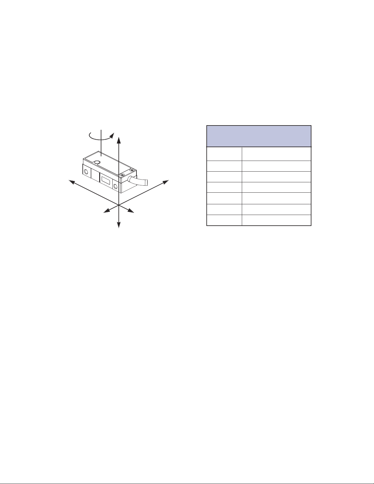
Sensor Mounting Orientation and Tolerances
Axis diagram.
q
z
OPS Side Mount Configuration
Sensor Alignment Tolerances
Axis Alignment Tolerance
X Direction of Motion
Y ± 0.20mm
Z ± 0.15mm
X
Z
Y
q
X
q
Y
q
Z
± 1.0°
± 1.0°
± 2.0°
Page 7
Page 8
Sensor Head Installation (Side Mount Configuration)
OPS™Series Encoders
1.
Install the Sensor
Use a wrench and M3 screws to install the sensor. Refer to interface drawing to make sure sensor is oriented
properly with reference to the scale.
2.
Verify Sensor Mounting Surface Height
Refer to the OPS interface drawing for detailed dimensions.
Use Z-Height spacer shim to verify that the Z-Height distance between
the bottom surface of the sensor and the top of the scale is as follows:
Tape Scales:
Use red spacer (1.00mm) to set the proper Z-Height for
PurePrecision Marker Tape II and Laser Tape II Scales
q
z
Axis Diagram
Glass Scales:
Use blue spacer (0.83mm) to set the proper Z-Height for
PurePrecision Performance and Value Linear Glass Scales
See step 3 below for installation steps.
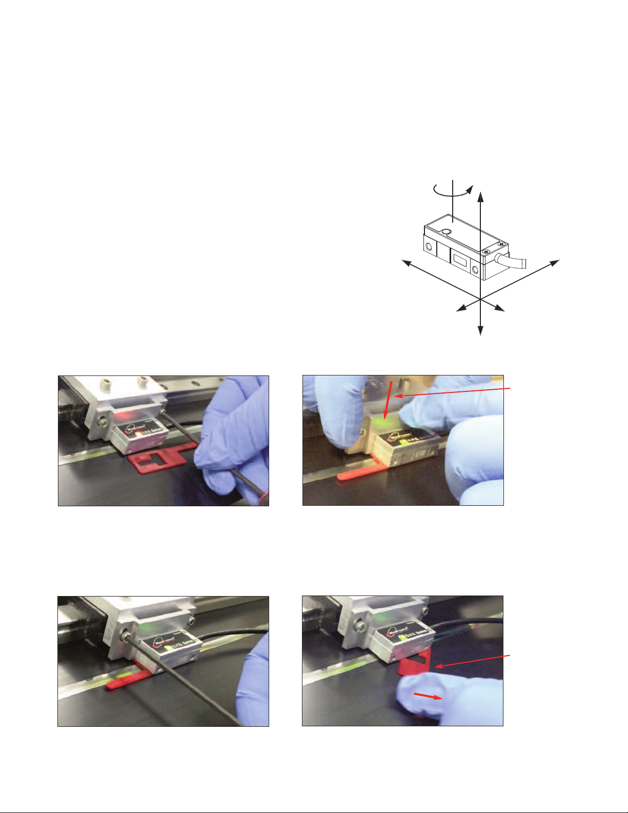
3.
Installation Steps
3.1 Loosen the sensor in the Z-axis
3.2 Place shim between the bottom of the sensor head
and the top of the scale and press down in the Z-axis.
Shim can be inserted either parallel or perpendicular
to the scale. The shim features cut-outs to allow
signal level to be monitored during sensor mounting.
X
Z
Y
Gently push the
sensor and
mounting against
the top of the
tape scale in the
z-axis.
3.3 Tighten the sensor in the Z-axis.
Rotational
movement to
remove shim.
3.4 Carefully remove the shim by rotating it off the
scale with the shim’s handle.
Page 8
Page 9

System Overview, OPS Top Mount
OPS™Sensor Installation
OPSTMSeries, Top Mount Configuration
System View
Status LED
Sensor
(shown attached on a linear slide base
with mounting bracket)
Scale
(shown mounted on a linear slide)
With OPS Series
Alignment Tool
Expanded View
Mounting screws
Sensor mounting holes (2)
Typical user-supplied
sensor mounting bracket
Double shielded cable
15 pin Standard
D-sub connector
Optional sensor
benching pins (3)
Center index mark
Bracket mounting holes (2)
Scale reference datum;
example shown with benching pins
Page 9
Page 10

Sensor Head Installation (Top Mount Configuration)
OPS™Series Encoders
Sensor Mounting Orientation and Tolerances
Axis diagram.
q
z
OPS Top Mount Configuration
Sensor Alignment Tolerances
Axis Alignment Tolerance
X Direction of Motion
Y ± 0.20mm
X
Y
Z
Z ± 0.15mm
q
X
q
Y
q
Z
± 1.0°
± 1.0°
± 2.0°
Page 10
Page 11

Sensor Head Installation (Top Mount Configuration)
OPS™Series Encoders
1.
Verify Sensor Mounting Surface Height
Refer to the OPS interface drawing for the latest dimensions.
Verify that the Z-height distance between the sensor mounting surface datum “A” and the top of the scale is as
follows:
Tape Scales:
Z-axis distance from top of tape scale after blue protective film is removed to Datum “A”
of sensor: 3.09 mm ±0.15
Z-Height Gauge (Model number ZG-PP1) can be used to verify proper Z-Height for PurePrecision Marker
Tape II and Laser Tape II scales
Glass Scales:
Z-axis distance from top of glass scale to Datum “A” of sensor: 2.93 mm ±0.15
Z-Height Gauge (Model Number ZG-GS1) can be used to verify proper Z-Height for PurePrecision
Performance and Value Linear Glass Scales
Use the correct gauge to check that there are no gaps between:
1.1 The mounting surface of the gauge and the mounting bracket, or
1.2 The bottom surface of the gauge and the scale.
Place the gauge in position and use the mounting screws as guides. If the bottom of the gauge hits the scale,
you will see the gap between the gauge bottom mounting surface and your mounting bracket surface.
If you hand tighten the sensor mounting screws, there should be no gap between the tape scale and the bottom
of the plastic gauge tool.
Mounting bracket
surface
Scale top surface
Z- Height Gauges
Tape Scales: P/N: ZG-PP1 (Black)
Glass Scales: P/N: ZG-GS1 (White)
2.
Install Sensor
Install the sensor on the mounting surface referencing the appropriate datum surface as shown on the Interface
Drawing. Use two M2 or 2-56 screws to loosely affix the sensor.
A benching edge is recommended to locate the sensor to meet the mechanical mounting tolerances. Refer to the
Interface Drawing for recommended location and height of edge.
Page 11
Page 12

Sensor Alignment - by Alignment Tool
OPS™Series Encoders, Side and Top Mount Configurations
OPS Alignment Tool
Sensor 15-pin D-Sub connector
(Side and top mount configurations;
side mount shown.)
Be sure the source power is off before connecting the
SmartPrecision Alignment Tool to the sensor plug.
1.
Connect the encoder (either Side Mount or Top Mount) to the
SmartPrecision Alignment Tool.
Connect the USB cable to either a computer’s USB port or to
the DC power supply provided.
OPS Alignment Tool kit, Model Number AT-OPS (Includes SmartPrecision II Software)
OPS Alignment Tool
Use Universal Power
supply with USB port for
Alignment Tool power if
not connecting to
computer USB port.
Mini USB computer interface cable
(plugs into either power supply or
computer)
To OPS Series
encoder sensor
Page 12
Page 13

Sensor Alignment - by Alignment Tool
OPS™Series Encoders, Side and Top Mount Configurations
2.
Alignment
Connect the USB cable to the Alignment Tool with power from either the Universal Power supply or computer
USB port.
The Alignment Tool Signal Level and Sensor head LEDs are now used for alignment. Proper alignment is
indicated by green sensor head and Alignment Tool Signal Level LEDs.
3.
Position the sensor over a section of the scale. Adjust the sensor's Y or qzdirections until the Signal Level and
sensor head LEDs are green.
4.
Move the sensor across the entire length of travel. The LED should be green over the entire length of travel. If
the LED is Yellow or Red, adjust Y and qzand refer to the interface drawing to ensure proper mechanical
design. (Passing over an Index will cause the Alignment Tool Index/Limit LED to flash green.)
OPS Side Mount
OPS Top Mount
X
Alignment Tool
Green = Optimal
Performance
Sensor
Indicator LED
Yellow = Marginal
Performance
q
z
To align the
sensor move it
in the Y or qz
directions
Red = Improper
Performance
Y
Z
NOTE:
If you are having any difficulties getting a green light over
the entire travel length, refer to the OPS interface drawing
to check mechanical design. Also, check to make sure the
scale is properly installed, the sensor is properly oriented
with respect to the scale, and the blue protective film has
been removed from the tape scales.
Page 13
Page 14

Sensor Calibration - by Alignment Tool
OPS™Series Encoders, Side and Top Mount Configurations
Calibration, Index, and Limits
1.
Press the Alignment Tool Cal button to start. (Be sure the sensor has been aligned to the scale, across the
entire length.)
Both the Alignment Tool Signal Level and Index/Limit LEDs will turn solid green. This starts the Gain Offset
Phase (GOP) calibration.
2.
Move the sensor back and forth anywhere on the scale, 10mm or more. This movement adapts and ends the
GOP calibration when the Signal Level LED turns blue, with the Index/Limit LED solid green.
3.
Index calibration: move the sensor back and forth across the index until both Signal Level and Index/Limit
LEDs turn blue. (At this step, the Index has been calibrated and the left limit is ready to be calibrated.)
NOTE:
Correct orientation of the scale for Left/Right Limit calibration is shown below. The
“D” datum edge from the OPS Interface Drawing is designated as the “Top” of the
scale. The Index/Limit track is also the “Top” track on a scale (tape and glass).
D
“D” datum edge of scale = “Top” of the scale.
“Left” side of scale
Index/Limit Track
“Right” side of scale
4.
Left limit calibration: move the sensor over to the “left limit” area on the scale, with both Signal Level and
Index/Limit LEDs solid
has been calibrated and the right limit is ready to be calibrated.)
blue. Push the Cal button. The Index/Limit LED will turn red. (At this step, the Left Limit
5.
Right limit calibration: Move the sensor over to the “right limit” area on the scale with Signal Level LED solid
blue and Index/Limit LED solid red. Push the Cal button. (At this step, the Right Limit has been calibrated.)
Both the Signal Level and Index/Limit LEDs will quickly flash
been completed.
(Note: to skip a step, push and hold the Cal button for 2 seconds until LEDs change color, then release button.)
Both Signal Level and Index/Limit LEDs
flash green 5 times to indicate
calibration complete.
green 5 times to indicate that calibration has
Page 14
Page 15

Sensor Alignment and Calibration - by SmartPrecision™ II Software
OPS™Series Encoders, Side and Top Mount Configurations
Install the OPS SmartPrecision II Software (included with Alignment Tool kit, AT-OPS):
NOTE:
Be sure the Alignment Tool is “not” plugged in to the computer USB while installing the software.
The Alignment Tool needs to be plugged in “after” the software is installed, in order to properly load
the USB driver.
1) Insert CD into drive. Installer should automatically start up and install SmartPrecision II software to
C:\Program Files\MicroE Systems\SmartPrecision_OPS.
2) If it does not start automatically browse to CD and run setup.exe to install software.
Install the USB Driver:
Windows 2000:
1) Connect the USB cable between the host computer and the OPS Alignment Tool/OPS Sensor.
2) When the electronics are on, Windows will notify you it has found new hardware prompting you with a
"Found New Hardware" wizard. Press the Next button.
3) Select "Search for a suitable driver for my device (recommended)" and press the Next button.
4) Select "Specify a location" under “Optional search locations:” and press the Next button.
5) Press the Browse button to locate the OPS.inf driver Installation file. It is located in the directory C:\Program
Files\MicroE Systems\SmartPrecision_OPS. Once this file is selected press the OK button.
6) Verify that the correct path and filename are shown and press the Next button.
7) Press the Finish button.
Windows XP, Vista, 7, and 8:
1) Connect the USB cable between the host computer and the OPS Alignment Tool/OPS Sensor.
2) When the electronics are on,, Windows will notify you it has found new hardware prompting you with a
"Found New Hardware" wizard.
3) The wizard may prompt “Can Windows connect to Windows Update to search for software?” Select “No, not
this time” and press the Next button.
4) Select "Install from a list or specific location (Advanced)" and press the Next button.
5) Select "Include this location in the search".
6) Press the Browse button to locate the MicroE_USB.inf driver installation file OPS.inf driver. It is located in the
directory C:\Program Files\MicroE Systems\SmartPrecision_OPS. Once this file is selected press the OK
button.
7) Verify that the correct path and filename are shown and press the Next button.
8) Press the Finish button.
Using the Software:
1) To Run Software, go to directory C:\Program Files\MicroE Systems\SmartPrecision_OPS. Double-click
‘OPS.exe’.
Page 15
Page 16

Sensor Alignment - by SmartPrecision™ II Software
OPS™Series Encoders, Side and Top Mount Configurations
Connect the encoder to the Alignment Tool before connecting USB cable. Connect the USB cable to the
Alignment Tool
Run SmartPrecision II Software
1. Align the sensor:
SmartPrecision II software automatically begins in Alignment Mode, with AGC off.
Position the sensor over a section of the scale. Adjust the sensor's Y or qzdirections until the Signal
Level is in the Optimal Green level.
Move the sensor across the entire length of travel. The Signal Level should be in the Optimal Green level
over the entire length of travel. If the Signal Level is in the Yellow or Red areas, adjust Y and qzand refer
to the interface drawing to ensure proper mechanical design. (Passing over an Index will cause the
Alignment Tool Index/Limit LED to flash green.)
Check that Index LED blinks as sensor passes over index. Tighten sensor mounting screws.
Sensor LED Indicator Indicates signal strength – green for optimal performance, yellow for marginal
performance, and red for improper performance. Sensor LED will blink as sensor passes over index.
Alignment Mode is turned off automatically when you begin sensor calibration.
NOTE:
If you are having any difficulties getting a green light over the entire travel length, refer to the OPS
interface drawing to check mechanical design. Also, check to make sure the scale is properly
installed, the sensor is properly oriented with respect to the scale, and the blue protective film has
been removed from the tape scales.
Page 16
Page 17

Sensor Calibration - by SmartPrecision™ II Software
OPS™Series Encoders, Side and Top Mount Configurations
Note: all procedures below must be performed at ≤1m/s relative motion between the sensor and
the scale.
NOTE:
Correct orientation of the scale for Left/Right Limit calibration is shown below. The
“D” datum edge from the OPS Interface Drawing is designated as the “Top” of the
scale. The Index/Limit track is also the “Top” track on a scale (tape and glass).
D
1.
Click appropriate
checkboxes before
calibrating:
Calibrate GOP
Calibrate Index
Set Left Limit
(optional)
Set right Limit
(optional)
“D” datum edge of scale = “Top” of the scale.
“Left” side of scale
Index/Limit Track
“Right” side of scale
2.
Click Start Cal
button.
3.
Move the sensor
back and forth
(Gain Offset
Phase).
4.
Move the sensor
back and forth
over the Index
until the Left
Limit blue light
turns on. (The
Index is now
calibrated.)
Note: It is important that if you choose to calibrate only the limits, the sensor must be
placed in the “no limit” area of the scale (neither the left or right limit) when you click the
“Start Cal” button.
Page 17
Page 18

Sensor Calibration - by SmartPrecision™ II Software
OPS™Series Encoders, Side and Top Mount Configurations
5.
Move the sensor
to the Left Limit
and click the Set
button.
7.
Calibration
complete.
6.
Move the
sensor to the
Right Limit and
click the Set
button.
8.
“Calibration Complete” message will disappear
after a few seconds, ending the calibration mode.
SmartPrecision II will automatically revert to the
mode in use prior to calibration.
Note: It is important that if you choose to calibrate only the limits, the sensor must be
placed in the “no limit” area of the scale (neither the left or right limit) when you click the
“Start Cal” button.
Page 18
Page 19

Appendix A
Specifications
System
OPS sensors are compatible with:
- PurePrecision™ Marker Tape II and Laser Tape II
- Linear and rotary glass scales
Scale Pitch 20µm
Signal Period 20µm
System Resolution 1
µ
m, 0.5µm, 0.1µm or
specify at time of ordering)
(
50n
m
Accuracy
Linear Tape Scale
Linear Glass Scale
Rotary Glass Scale
1
Achievable after two-point correction in the customer’s controller.
2
Repeating error over any 20
3
Assumes perfect alignment of scale pattern to axis of rotation.
Note: Accuracy is the maximum error over the specified movement when
compared to a NIST-traceable laser interferometer standard used at 20
Typical slope error: 100ppm
- Linearity: ±5µm/m
- Cyclical (interpolation) error: ±40nm
1
±3µm/m total
- Cyclical (interpolation) error: ±25nm
3.9 arc-sec with 64mm OD scale
- Cyclical (interpolation) error: ±0.2 arc-sec
µm movement and does not accumulate.
3
o
2
2
C.
Sensor Size & Weight (side mount sensor)
Height Width Length
0.46 [11.67mm] 0.56 [14.30mm] 1.35 [34.25mm]
Weight 8g (without cable)
Reliability Information
5 Year Expected Reliability >99.8% under normal operating
conditions
Digital Output Signals
Operating and Electrical Specifications
Power Supply 5VDC +5% @ 120mA when used with
recommended termination, 80mA unterminated
Temperature
Operating 0 to 70
o
C
Storage -20 to 85oC
Humidity 10 to 90% RH non-condensing
Agency Standards Conformance: In accordance with
Electromagnetic Compatibility Directive 2004/108/EC:
EN 55011:2007
EN 61000-4-2, -3, -4, -6
Shock 300G 0.5 ms half sine
Vibration 30G at 17Hz
Sensor Cable Double Shield
(contact MicroE Systems for applications >5m)
2
Diameter 3.6mm (0.142")
Flex Life 20x10
6
cycles @ 20mm bending radius
Standard 15 pin D-sub connector
Outputs
Digital A-quad-B, 1LSB index pulse, left and right limits. A, B
and I signals are differential. Limits are single ended. Index is
gated to AB high.
Signal Level
A/B/I (differential): RS-422 compatible
Limits: 3.3VDC max., LVTTL compatible (High>2.4VDC, Low
<0.4VDC), maximum current output (source and sink): 14mA
Limits programmable as active high, active low or disabled
Alarm: Tri-state of A, B and I outputs, latched for minimum 30ms
Output Frequency (at maximum speed)
OPS 200/400: 16.5Mhz per channel
OPS 40: 5Mhz per channel
OPS 20: 2.5Mhz per channel
Note: Output frequency must not exceed maximum input frequency of customer
electronics.
Quadrature and Index
Pins 14 & 6
Pins 13 & 5
Pins 12 & 4
Inverse signals are not shown for clarity.
A
B
I
Left Limit Marker
0.6mm ± 0.3*
Left Limit Out
Pin 11
Limits
³ 5mm
Active low limit configuration is shown.
³ 5mm
Right Limit Marker
Page 19
0.6mm
± 0.3*
Right Limit Out
Pin 10
* With reference to the sensor‘s optical centerline (see
interface drawings).
Page 20

Appendix B
!
!5
!'
!
Wiring Diagrams
Connector Pin Configuration
ER
N
N
I
d
n
a
D
GN
OTE:
N
Recommended Signal Termination
Digital Outputs:
OPS Series
Encoder
A, B, I
A, B, I
SH
IEL
+
-
AR
D
TER
E IN
Cable Zo=
120 W
.
TED
EC
N
ON
LY C
AL
N
120
W
Customer
Electronics
Standard RS-422 Line Receiver Circuitry
Max cable length: 5m. Contact MicroE Applications Engineering if longer length required.
Grounding Considerations
Sensor mounted with good electrical contact to well grounded surface (preferred):
INNER SHIELD:
Insulated from outer shield, sensor case, and
connector housing. Connected to circuit common
internally as supplied by MicroE Systems
OUTER SHIELD: Connected to
sensor and connector housing
Electrically conductive mechanical
connection (as supplied by MicroE
Systems).
Sensor mounted to poorly grounded or non-conducting surface:
POWER
SUPPLY
5 Volts
0 Volts
POWER
SUPPLY
5 Volts
0 Volts
Page 20
Page 21

Appendix C
Interface Cable Requirements
1. Customer Interface Cable Requirements
Customer cables that interface to OPS™series encoders must have the following characteristics:
• Twisted pair signal wiring.
• Characteristic impedance of 100-120 ohms.
• Sufficient wire gauge to meet the minimum voltage requirement at the encoder, for example 24AWG
gauge wire for a 2m length cable. Examples of acceptable cables with 24AWG gauge wire and 4
twisted pairs are Belden 9831, 8104, and 9844 or other manufacturer’s equivalents.
• Single shield cable with a minimum of 90% coverage. Note that a double shielded cable may be
required in high-noise applications.
2. Signal Wiring
Each differential signal should be connected to a corresponding twisted pair as follows:
OPS Series
Signal Twisted Pair
A+ Pair 1
A-
B+ Pair 2
B-
Index+ Pair 3
Index-
+5V Pair 4
GND
Left Limit Pair 5
Right Limit
3. Shield Termination:
The customer's cable shield should be in 360° contact with the connector shroud and the connector shell to
provide complete shielding. The connector shell should be metal with conductive surfaces. Suggested metal
connector shells for use with OPS™ encoders: AMP 748676-1 or equivalent. The shield should be terminated
as illustrated in the following diagram.
Jacket
Aluminum
Polyester
Shied
Braided
Shield
Fold braided shield back over jacket. Example shows double-shielded cable.
Dimensions shown are for illustration only.
Page 21
Page 22

Appendix D
RS-422 Compliance
The OPS Series is RS-422 compatible. Encoder signals are “sending end terminated.” Therefore customer
receiving terminations are not required. If you elect to use them, the supply current will increase.
Optional RS-422 compliant circuitry for long cable runs in harsh electrical environments is illustrated below.
Page 22
Page 23

Appendix E
Troubleshooting
Problem
The Sensor LED indicator won’t turn on.
Solution
• Make sure that the OPS Series electronics’ 15-pin D-sub connector is fully seated and connected.
• Confirm that +5 Volts DC is being applied to the OPS Sensor. Refer to the OPS interface drawing for
proper pinouts.
Problem
Can't get the OPS Series electronics’ "Signal" OPS better than red or yellow; or the green, “ Proper
Alignment” indicator doesn't stay illuminated over the full length of the scale.
Solution
• Verify that the sensor is mounted in the correct orientation with reference to the scale and scale
mounting reference edge. Refer to the Interface Drawing.
• Verify that the sensor has been aligned to the scale and that the mounting screws are tight. Check the
dimensions for the mechanical mounting holes (and clamps if any) to make sure that the sensor is
correctly located over the scale in the Y and Z dimensions. Refer to the Interface Drawing.
• Check that the scale is firmly mounted and can't jiggle or move in any direction.
• Make sure that the scale is clean over its entire length or circumference.
Page 23
Page 24

Appendix F
Order Guide
How to Order
Sensor
OPS-SM
* Custom cable lengths and connectors are available.
Sensor Installation Tools
-400 –3 –1
s
t
u
p
t
u
O
t
i
m
i
L
w
o
L
e
v
i
t
c
A
=
1
h
g
Hi
e
v
i
t
c
A
=
2
d
e
l
b
a
s
Di
=
3
*
h
t
g
n
e
L
e
l
b
Ca
m
0
.
1
=
1
m
0
.
3
=
3
m
0
.
5
=
5
(Resol
on
i
at
erpol
nt
I
m)
µ
(1
x20
=
20
m)
µ
5
(0.
x40
=
40
m)
µ
1
(0.
x200
=
200
(50nm)
x400
=
400
Mount
de
i
S
=
M
S
Mount
= Top
(blank)
Contact MicroE Applications Engineering.
ut
on)
i
Scales
PurePrecision™ Marker Tape II
HPMT – N – A –L– 5000 –I
I = Individual Lengths
C = Continuous reel with index and
cut marks (unless otherwise
specified)
Length in mm (40mm - 30,000mm)
For length >5000mm, contact
MicroE for custom P/N.
L = Center Index and End Limits
I = Center Index Only
C = Custom
PurePrecision™ Laser Tape II
HPTS – 30000 –N
Length in mm (70mm - 30,000mm)
Performance and Value Linear Glass
PVGL – 1000 –T
AT-OPS
ZG-PP1 Z-Height Gauge, PurePrecision™ Tape
ZG-GS1 Z-Height Gauge, Glass Scales, Top
Alignment Tool Kit for OPS encoders
includes Alignment Tool, SmartPrecision II™
Software, USB Cable, Power Supply (100V240VAC, US 2-prong plug)
Scales, Top Mount Sensor
Mount Sensor
FlexFit™ Adaptor
MK-FFA
FlexFit Adaptor Mounting Kit. Reference
design is available upon request.
End Cap Kit, PurePrecision Tape Scales
EC
Optional T
ape Scale
End Caps
Adaptor for Open Collector Limit Outputs
MIIA-OCL Small DB15 adaptor to convert 3.3V left
and right limit output signals to open
collector type (7407).
All specifications subject to change.
T = Adhesive backing
Length in mm (70mm - 1,000mm)**
** For lengths <70mm or >1m, contact MicroE Applications
Engineering.
Stick-on Index and Limit Markers (for Laser Tape II and
Performance and Value Linear Glass Scales)
NRIMS Qty. 8 Stick-On Index Markers
NRLMS Qty. 4 Stick-On Left Limit Markers and Qty. 4
Stick-On Right Limit Markers
Rotary Glass
Contact MicroE Applications Engineering to discuss
your requirements.
Tape Scale Applicator Tools
(use for lengths >300mm)
TSAT-SM-PPT
TSAT-PPT
Tape Applicator Tool for OPS-SM,
Side Mount Sensors
Tape Applicator Tool for OPS,
Top Mount Sensors
Page 24
Page 25

Contacting MicroE
MicroE Systems is a world leader in optical encoder technology with
offices in major industrial centers around the globe.
To learn more about MicroE Systems products, visit:
www.microesystems.com.
Our products have been used by thousands of companies worldwide to
solve a wide range of motion control applications. Our advanced
encoder technology and application expertise has driven innovations in
the design of machinery, equipment and instrumentation in many
industries, including medical, industrial, robotics, automation, metrology,
semiconductor manufacturing, packaging equipment, entertainment,
energy, military, and scientific research.
© 2015 MicroE Systems
MicroE Systems
125 Middlesex Turnpike
Bedford, MA 01730 USA
T 781-266-5700
F 781-266-5112
info@microesystems.com
www.microesystems.com
Page 25
 Loading...