

Page 1
Page 1
PurePrecision
™
Tape and Glass Scale Installation
for OPS Series Encoders
Installation Manual
and Reference Guide
MicroE Systems • 125 Middlesex Turnpike • Bedford, MA 01730 • USA
www.microesystems.com [email protected] T. 781-266-5700
OPS-IM PurePrecision Scale Installation Rev A1
© 2015 MicroE Systems
Page 2

Page 2
Table of Contents
PurePrecision™Scale Installation
Introduction
Introduction (Precautions, Patents, Manual Revisions) ............................................................................3
Overview ....................................................................................................................................................4
Items Required for Scale Installation ........................................................................................................4
Pre-Installation Information and Precautions ............................................................................................5
Design Guidelines for Side Mount and Top Mount Configurations............................................................6
Mounting Surface Preparation for Side Mount and Top Mount Sensors ..................................................7
Cutting PurePrecision Tape Scales ..........................................................................................................8
Tape Scale, Lengths <300mm
By Hand, for OPS Side Mount and OPS Top Mount ................................................................................9
Tape Scale, Lengths >300mm
By Applicator Tool, for OPS Side Mount ................................................................................................13
By Applicator Tool, for OPS Top Mount ..................................................................................................19
Linear Glass Scales, OPS Top Mount
Mounting Surface Preparation ................................................................................................................25
Mounting Linear Glass Scales ................................................................................................................26
Stick-On Index and Limit Marker Installation (Tape and Glass Scales)
Packaging, Index and Limit Strips............................................................................................................27
Stick-on Index and Limit Installation ........................................................................................................28
End Cap Installation (Tape Scales)
End Cap Installation ................................................................................................................................31
Final Clean, Inspection, Cure Time, and Rework ..............................................................32
Contacting MicroE Systems ..............................................................................................................33
Page 3

Page 3
Precautions
Follow standard ESD precautions. Turn power off before connecting the sensor. Do
not touch the electrical pins without static protection such as a grounded wrist strap.
Do not touch the glass scale unless you are wearing talc-free gloves or finger cots.
Please read this installation manual for full instructions.
1
2
OPS models are CE and RoHS compliant.
Manual Version Numbers
IM-PurePrecision Scales OPS Rev A, issued January 2014
Changes: N/A
Related Documents
-OPS Data Sheet
-OPS Sensor Installation Manual
-OPS Interface Drawing
RoHS
Page 4

Page 4
Overview
This manual applies to the installation of the following scale types.
• PurePrecision Marker Tape II for OPS Series, Model HPMT-
• PurePrecision Laser Tape II for OPS Series, Model HPTS-
• PurePrecision Performance and Value Linear Glass Scales
for OPS Series, Model - PVGL-T (adhesive backed)
• PurePrecision Rotory Glass Scales OPS Series, Model - RXXXX
Items Required for PurePrecision Scale Installation
You will need the following items available:
• Shears (recommend, Clauss, Item# 18003)
1
• Tape Applicator Tool, for applications >300mm (not required for installations <300mm)
1
OPS Side Mount Configuration tool Model Number: TSAT-SM-PPT
OPS Top Mount Configuration tool Model Number: TSAT-PPT
• Finger Cots or talc-free gloves
1
,
2
• Acetone or isopropyl alcohol
1
,
2
• Lint-free cotton cloths or wipes
1
,
2
• Index and Limit Marker stick-on sheets or Strips
1
(optional, for Laser Tape II and Precision and Value Glass scales):
- Limit Marker Strips, Model Number: NRLMS
- Index Marker Strips, Model Number: NRIMS
• End caps (optional)
1
• Two-part epoxy (Tra-Con Tra-Bond 2116)
1
,
2
• Stick and disposable surface for stirring epoxy
1
,
2
Refer to encoder model data sheets for detailed ordering guide and more information
about MicroE Part Numbers.
1
Items needed for PurePrecision Tape Scales
2
Items needed for Performance and Value Linear Glass Scales
Page 5
Page 5
Pre-Installation Information and Precautions
Read all instructions completely before beginning the
installation process.
The PurePrecision
™
Tape Scale is a precision metrological device. Handle it
with the utmost care at all times.
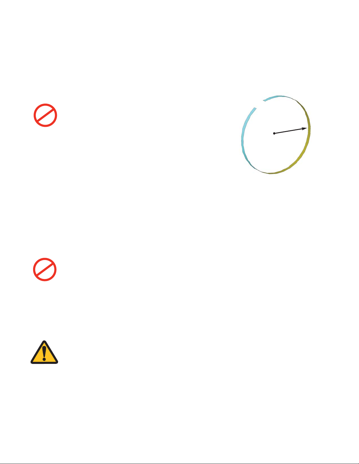
Avoid bending the tape scale to a radius less than 90mm (3.5
inches)
Avoid twisting the PurePrecision Tape Scale.
Do not let any sharp object touch the tape scale after the blue
protective film is removed.
The PurePrecision Tape Scale is protected by a blue film on
the top that prevents contamination and damage to the grating
pattern during installation.
Once the adhesive on the tape scale is exposed (by removing
the adhesive liner), do not touch the adhesive or allow any
contamination to come into contact with it.
PurePrecision Tape Scale, Index and Limit Markers are
designed for one time installation only.
If removed from the mounting surface for any reason, they
should not be used for any kind of reapplication. This will affect
the performance and reliability of the encoder system.
Minimum
storage radius
90mm (3.5 inches)
The adhesive on the PurePrecision™Tape Scale is permanent.
Do not touch the adhesive once the adhesive liner is removed.
Do not remove the tape scale from the mounting surface once it has been installed.
Do not reinstall the tape scale if it has already been installed once.
Avoid any contamination to the adhesive. Any particulate matter or other contamination that
is trapped between the scale and the mounting surface will affect encoder performance.
NOTE:
MicroE does not recommend installing PurePrecision Tape Scale
on a curved (cylindrical) surface.
Page 6

Page 6
Design Guidelines
1.
Verify the tolerances of the scale's mounting
surface given in the Interface Drawing.
2.
Verify the dimensions of the scale benching
edge (groove or straight edge) given in the
Interface Drawing.
3.
Calculate the length of PurePrecision™Tape Scale
required for your application. Refer to the Interface
Drawing.
4.
Tape scales less than 300mm can be installed by
hand against a straight edge. For lengths greater
than 300mm, tape scale applicator tools are
needed:
Side Mount Configuration:
Applicator tool Model Number: TSAT-SM-PPT
Top Mount Configuration:
Hand Grip Applicator tool Model Number:
TSAT-PPT
5.
If the tape scale is being installed into a 6mm
grove, it must be installed by hand (regardless of
scale length). Refer to the Interface Drawing.
6.
If machining the mounting surface is undesirable,
or not possible, a temporary straight edge can be
used that meets the dimensions and tolerances
specified in the Interface Drawing.
Two kinds of temporary straight edge can be
used -
• Type I (thin)-
Temporary Straight Edge of thickness
0.76 ± 0.05 mm (0.030 ± 0.002 inches).
Refer to the Interface Drawing for additional
dimensional requirements. A steel rule may be
one of the options for this type of temporary
straight edge.
• Type II (thick)-
Temporary straight edge with minimum
thickness 9.53mm (0.375 inches). Refer to the
Interface Drawing for additional dimensional
requirements.
NOTE:
See the appropriate section on Tape Applicator Tool
installations.
Page 7

Page 7
Mounting Surface Preparation
1.
Inspect the mounting surface for any machining irregularities. MicroE Systems recommends a surface finish
of better than 1.6 micrometers Ra.
2.
The straight edge (either permanent or temporary) must be sharp on the benching side in order for the
Applicator Tool to use it as a guide. In order for the tape scale to be mounted close to the straight edge, the
maximum radius of 0.127 mm (0.005 inches) should be used where the edge meets the bottom of the
mounting surface.
3.
Thoroughly clean the scale mounting surface and reference edge using a cotton swab or lint-free cloth
dampened with isopropyl alcohol or acetone.
Remove all dust and particles.
4.
Mark the starting location on the mounting surface where the tape scale will be applied. Also mark the
locations where the index and limit markers will be applied. Refer to the Interface Drawings to identify the
reference points of the markers.
Page 8
Page 8
Cutting the PurePrecision™Tape Scale
1.
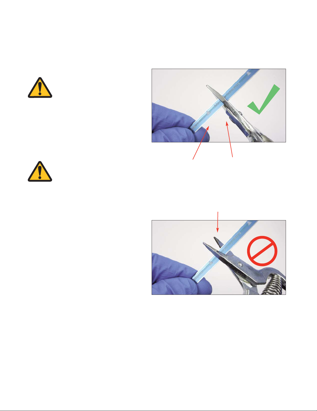
Uncoil the tape scale and cut it to the
required length using shears.
Note: check the interface drawing to make
sure the scale is cut to the right length.
Securely hold the tape scale close
to the shear (at an approximate
distance of 40mm [1½ inches])
near the point of cutting.
Orient the tape scale
perpendicular to the shear.
Cut the tape scale in a smooth,
continuous motion.
Shear held perpendicular to
the tape scale (NOT INCLINED)
Hand approximately at a
distance of 40mm-50mm
(1 1/2 inches to 2 inches)
from the cutting point
Shear held inclined,
not perpendicular,
to the tape scale
NOTE:
When working with any encoder
scale, it is important to use either
finger Cots or talc-free gloves
Page 9
Page 9
Tape Scale, OPS Side/Top Mount Configurations
Installation By Hand
2.
Removing/peeling the bottom
adhesive liner.
PurePrecision Tape Scales have 3 layers,
blue protective film, steel scale, and
adhesive backing.
Remove/peel back approximately 25mm
(1 inch) of the bottom adhesive liner, taking
care not to touch the adhesive or allow any
particulate contamination.
NOTE:
Do not peel the blue protective
film off at this time.
Adhesive liner peeled off about
25mm (1 inch) from one end
LEFT RIGHT
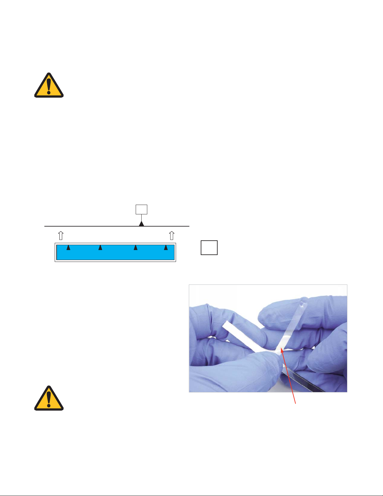
1.
Scale direction/orientation
Orient the scale such that the "arrowheads" on the blue protective film are pointing towards the mounting
surface reference edge “D” as shown in the interface drawings for your sensor model.
Refer to the correct model number Interface Drawing for reference edge “D” dimensions and sensor
orientation. Download the latest Interface Drawing at www.microesys.com/products/documentation
D
= Mounting Surface Reference Edge
NOTE:
For best system performance, talc-free gloves or finger cots should be worn during all
steps of tape scale installation.
Thoroughly clean the scale mounting surface and reference edge using a cotton swab
or lint-free cloth dampened with isopropyl alcohol or acetone. Remove all dust and
particles.
D
Page 10
Page 10
Tape Scale, OPS Side/Top Mount Configurations
Installation By Hand
4.
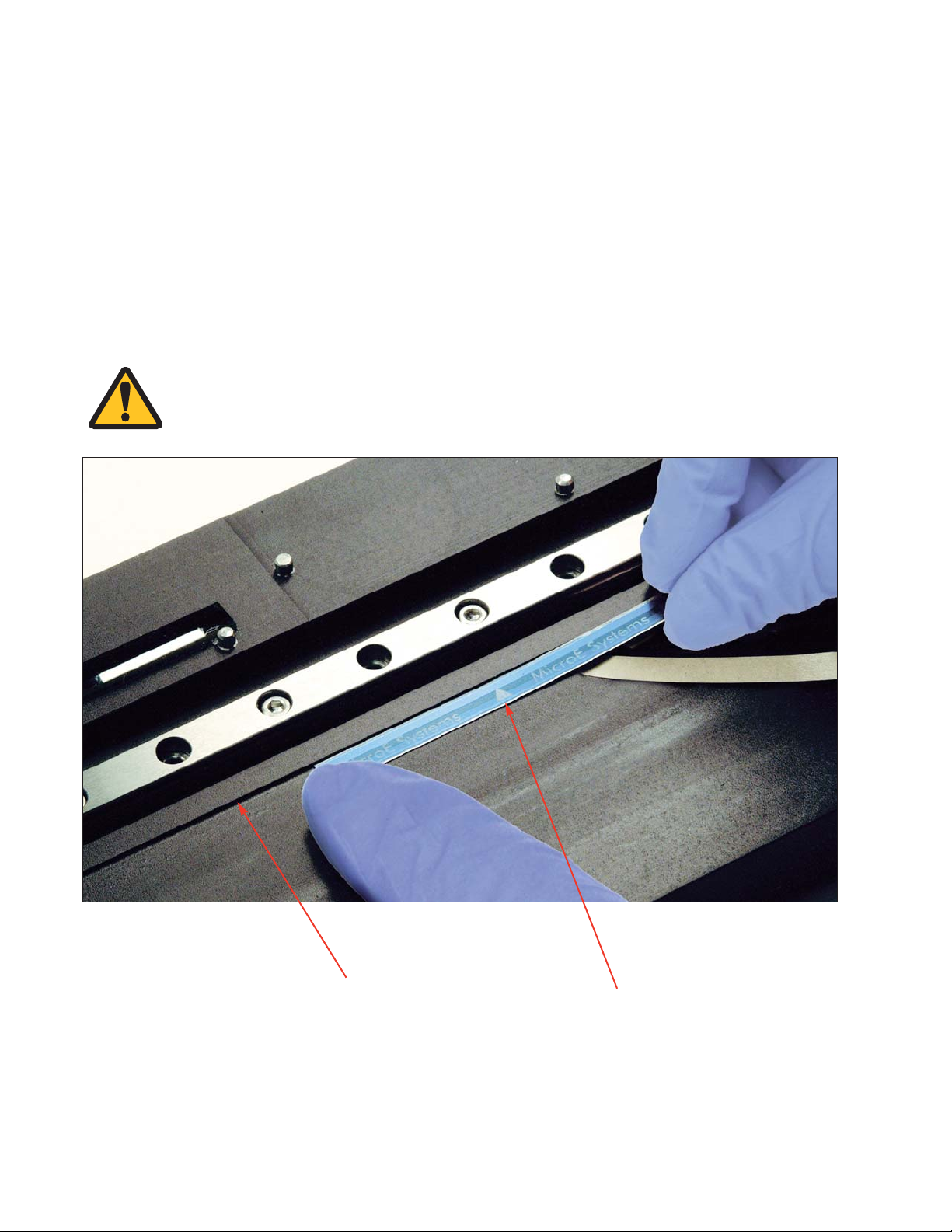
Place the PurePrecision™Tape Scale against the mounting surface “D” reference edge.
Place the 25mm (1 inch) exposed adhesive end of the tape scale against the mounting surface “D” reference
edge as shown and press firmly on the end.
NOTE:
Adhesive exposed by removing the adhesive bottom liner can touch the mounting
surface only once.
3.
Flip the tape over with the 25mm (1 inch) exposed adhesive surface facing down. Be sure not to touch or
contaminate the exposed adhesive surface. Be sure the orientation arrows on the blue protective film point to
the “D” reference edge.
“D” reference edge as shown in the
OPS interface drawing.
Tape scale orientation arrows.
Page 11
Page 11
Tape Scale, OPS Side/Top Mount Configurations
Installation By Hand
5.
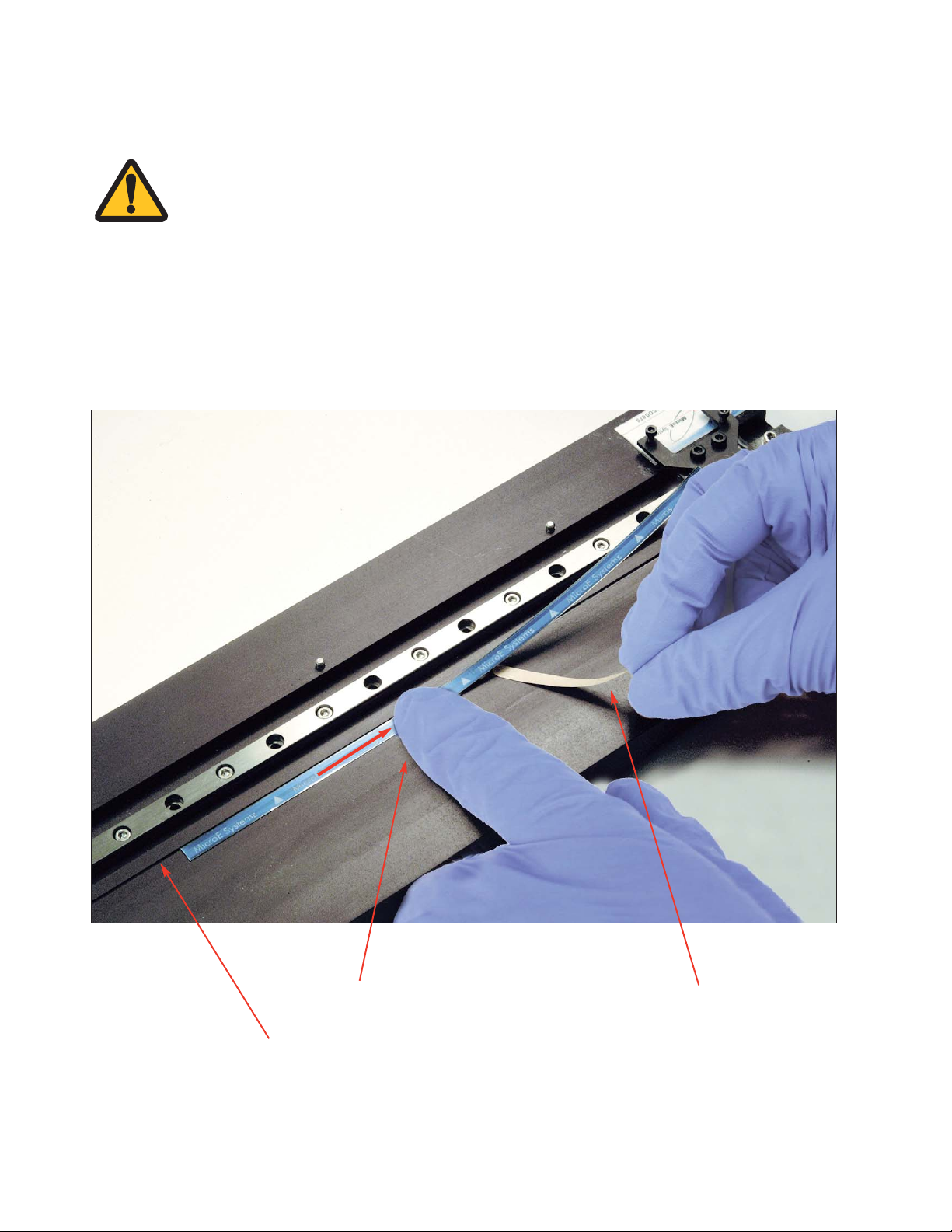
Install the PurePrecision Tape Scale along the remaining length of the mounting surface.
Press the remaining tape on to the mounting surface with a sliding motion as shown below.
Pull the adhesive liner out of the way during the sliding motion.
NOTE:
Make sure that the tape scale is tight against the “D” reference edge.
Pull adhesive liner out of the way
during sliding motion
Sliding motion of finger along the
length of the tape
NOTE:
Be sure to keep the blue top protective film in place.
“D” reference edge as shown in the
interface drawing.
Page 12
Page 12
Tape Scale, OPS Side/Top Mount Configurations
Installation By Hand
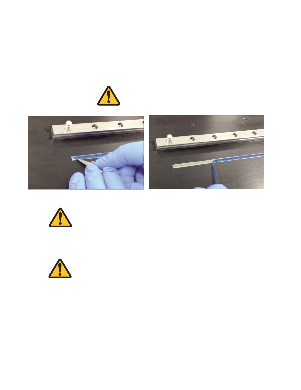
6.
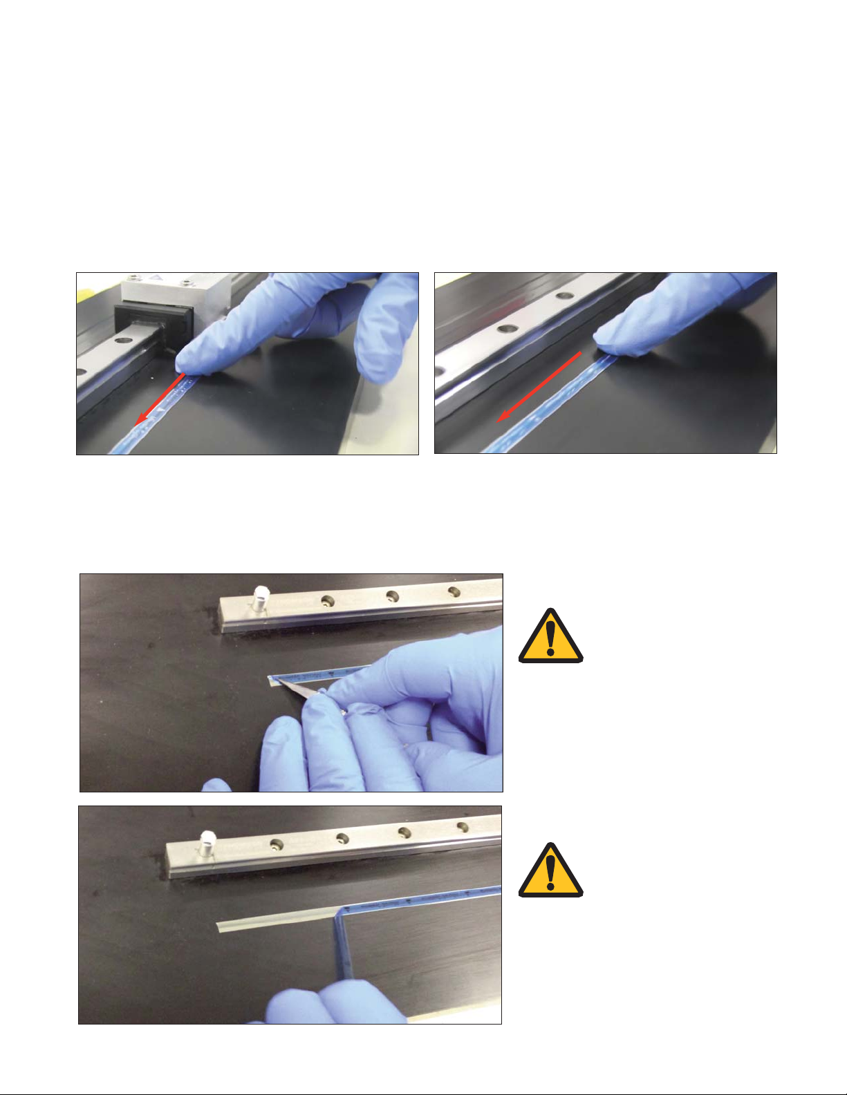
Once the scale is applied to the mounting surface, and before the blue protective film is removed, it is
recommended that even pressure be applied over the entire tape scale length by sliding a glove or cot
protected finger across the scale. The applied pressure will ensure that the adhesive is evenly and
permanently set.
7.
Peel off the blue protective film.
Start the peeling process using a sharp tool, being careful not to damage the scale. Pull off the remaining blue
protective film.
NOTE:
After removing the blue
protective film, the scale is
ready for use and will
perform to specification.
The encoder will not
function properly with the
blue protective film
installed. It must be
removed for proper encoder
operation.
NOTE:
If installing index/limits
(Laser Tape II and PVGL
glass), go to the “Stick-On
Index and Limit Marker
Installation” section.
Page 13
Page 13
Tape Scale, OPS Side Mount Configuration
Installation By Mounted Applicator Tool
1.
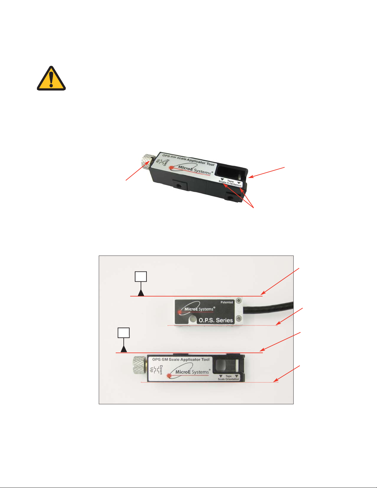
OPS Side Mounted Tape Scale Applicator Tool (Model Number: TSAT-SM-PPT)
The mounted application tool is needed for scale lengths greater than 300mm. It is mounted in the same
fixture as the OPS Side Mount Sensor.
Tool orientation
arrows
Tool contact cylinder knob
Tape entry
channel
2.
Tape Scale Side Mount Applicator Tool orientation to the “A” reference sensor mounting surface.
The “A” mounting surface is shown in the OPS interface drawing. The corresponding “A” reference mounting
surface of the Applicator Tool is shown below.
Applicator Tool
Mounting Surface “A”
Mounting Surface “A” (see the OPS interface drawing)
A
A
OPS Side Mount Sensor
Mounting Surface “A”
Sensor Alternate
Mounting Surface*
Applicator Tool Alternate
Mounting Surface*
*The OPS-SM Tape Scale Applicator Tool, is designed to be mounted on either Sensor mounting
surfaces. The proper orientation of the OPS-SM Applicator Tool in relation to the “A” mounting surface
and “Alternate mounting surface,” is shown above.
NOTE:
For best system performance, talc-free gloves or finger cots should be worn during all
steps of tape scale installation.
Thoroughly clean the scale mounting surface and reference edge using a cotton swab or
lint-free cloth dampened with isopropyl alcohol or acetone. Remove all dust and particles.
Page 14
Page 14
Tape Scale, OPS Side Mount Configuration
Installation By Mounted Applicator Tool
3.
Mount the Applicator Tool.
Mount the Applicator Tool in the Sensor mounting holes. Use the Z-height shim to set up the approximate
Z-height, to ensure proper Applicator Tool function.
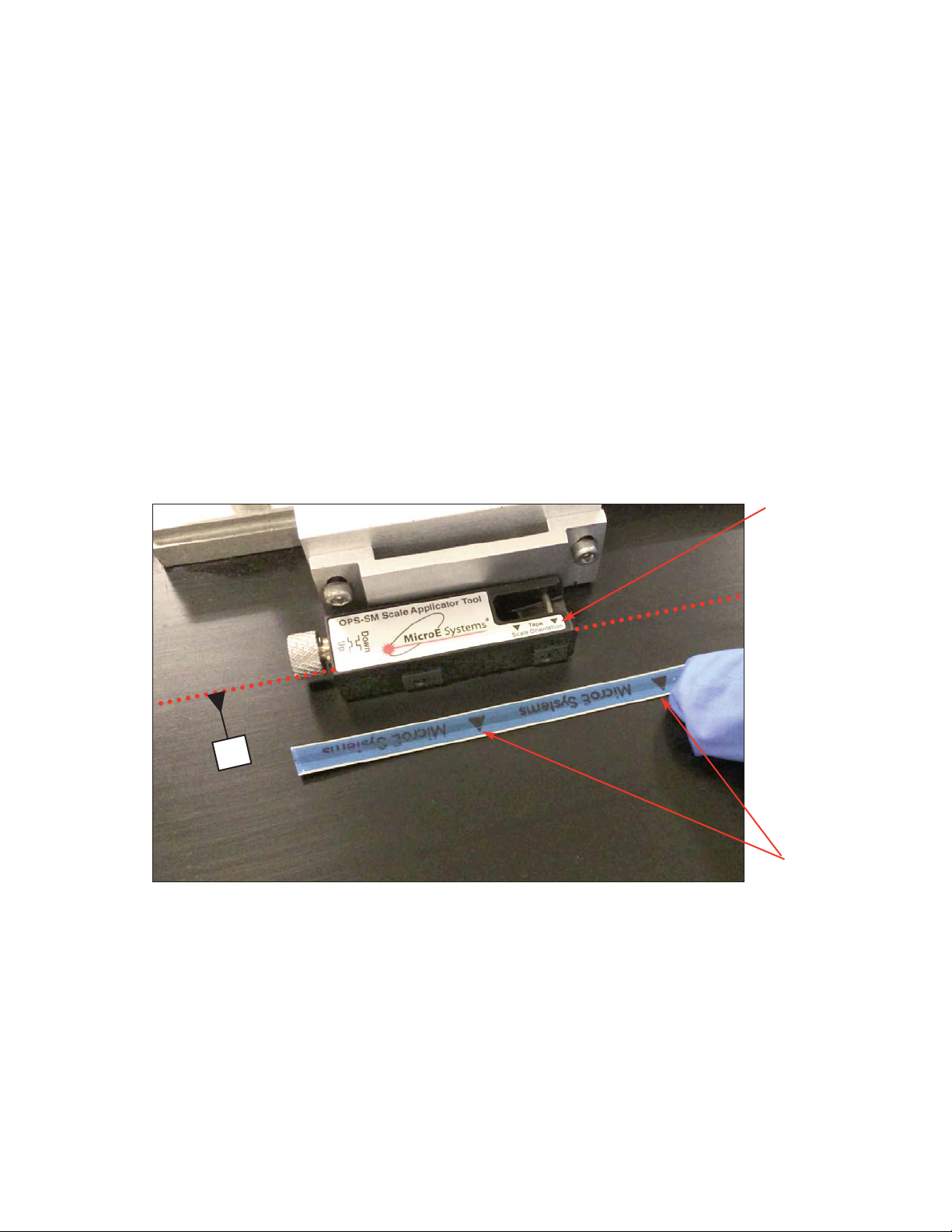
4.
Note tape scale orientation with arrows and the “D” reference edge.
The applicator tool is shown mounted to the OPS Sensor mount. Both Tape Scale arrows, and Applicator Tool
orientation arrows need to point in the same direction for proper configuration.
Also note, the “D” reference edge is determined from the OPS interface drawing. The tape scale orientation
arrows always point to the “D” reference edge. In the example below, the dotted red line shown is the
measured “D” reference edge. When the tape scale is finally installed, the orientation arrows will be pointing to
the calculated “D” reference edge.
In the example shown, the left side of the tape scale needs to go into the applicator tool entry channel first.
Tape Scale
orientation arrows
Tool orientation
arrows
D
Page 15
Page 15
Tape Scale, OPS Side Mount Configuration
Installation By Mounted Applicator Tool
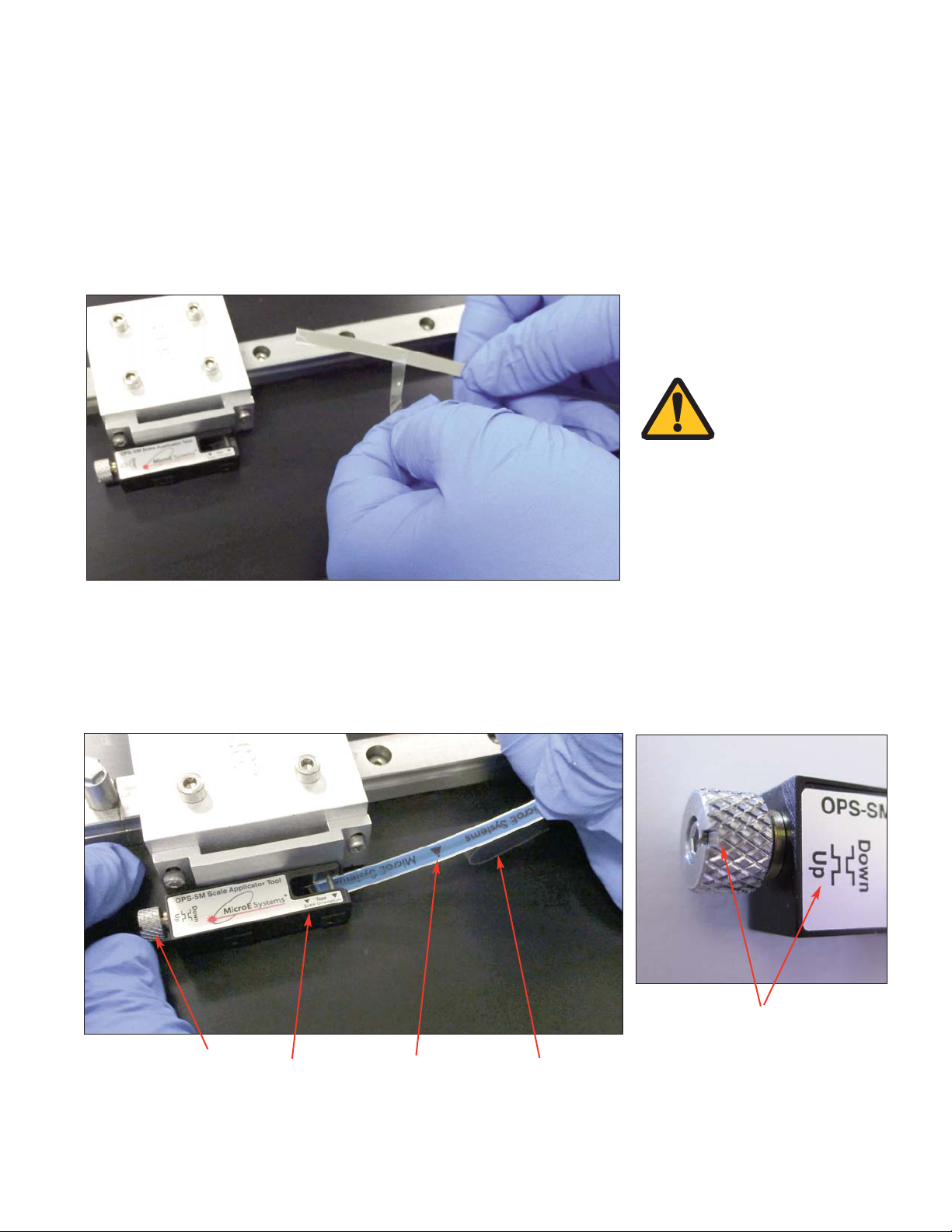
5.
Peel off a short section of bottom adhesive backing approximately 50mm (2 inches).
PurePrecision Tape Scales have 3 layers, blue protective film, steel scale, and adhesive backing.
Using a sharp tool or fingernail, initiate the peeling of the adhesive liner from the end of the tape scale that will
be inserted into the applicator tool entry channel.
6.
Turn Applicator Tool to the “Up” position and insert tape into applicator tool.
Rotate the knob that controls the contact cylinder plunger to the UP position. This allows you to insert the first
section of adhesive exposed tape, into the applicator tool.
Be sure that both the tape scale orientation arrows and the applicator tool arrows point in the same direction.
Tape Scale
orientation arrows
Tool
orientation arrows
Plunger in UP
position
Close-up of plunger knob in the UP
position. The position of the keyways
indicates UP or Down. Rotating the knob
will both move the plunger up or down.
Adhesive backing
liner
NOTE:
Do not peel the blue
protective film off at
this time.
Page 16
Page 16
Tape Scale, OPS Side Mount Configuration
Installation By Mounted Applicator Tool
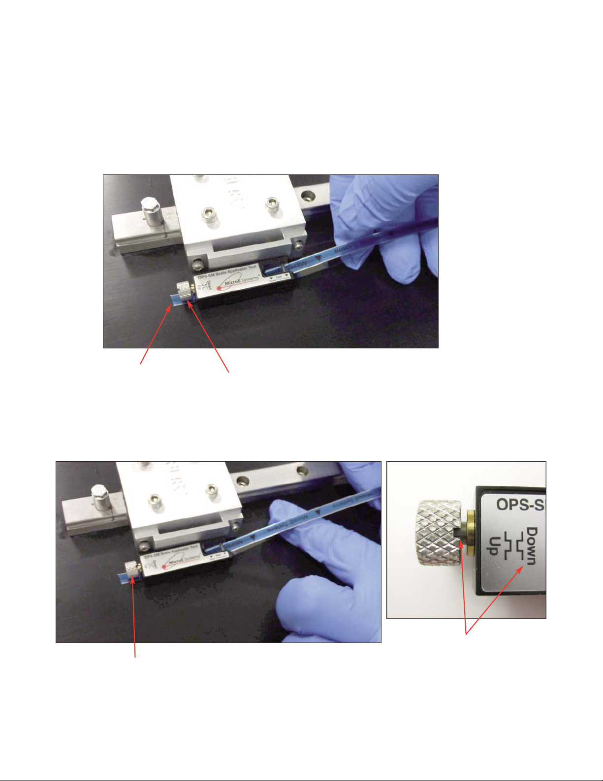
7.
Insert a short section of tape scale into the tool, approximately 50mm (2 inches).
Insert the first short section of tape scale so that it emerges just past the plunger knob to a desired end
location. Press down on this exposed 3-5mm section of tape.
Plunger in the UP position
Press down on this
small section of tape
8.
Rotate the pressure plunger knob to the “Down” position.
Rotate the plunger knob so that the key-way notch is in the position shown.
Plunger knob in the
DOWN position
Close-up of plunger knob in the
DOWN position. Position of notch
indicates that the plunger is in the
DOWN position.
Page 17
Page 17
Tape Scale, OPS Side Mount Configuration
Installation By Mounted Applicator Tool
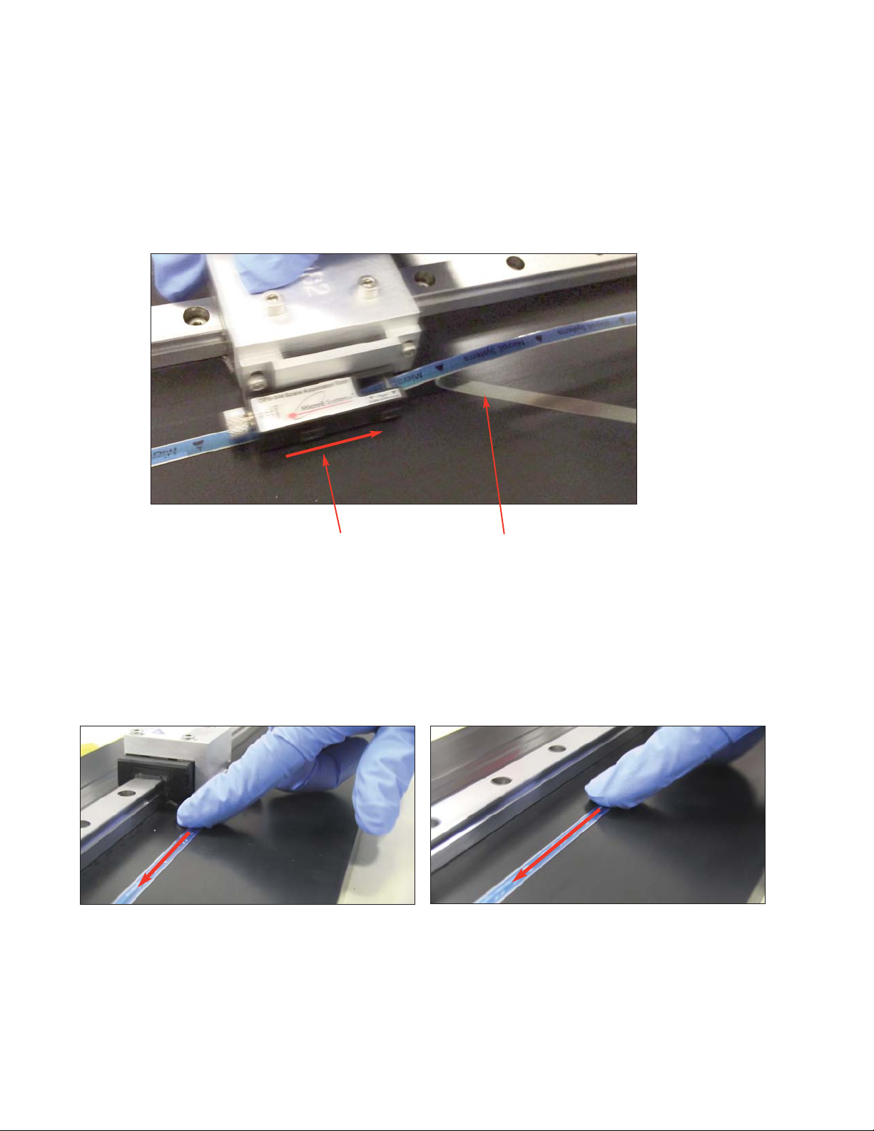
9.
Move the tool in a steady motion to apply the tape scale.
Push the applicator tool in the direction of tape application. Be sure to pull the adhesive backer out of the way
while the applicator is in motion.
Pull adhesive backer away from
tape applicator, while moving the
applicator tool.
Direction of motion of tape
applicator tool.
10.
Once the scale is applied to the mounting surface, and before the blue protective film is removed, it is
recommended that even pressure be applied over the entire tape scale length by sliding a glove or cot
protected finger across the scale. The applied pressure will ensure that the adhesive is evenly and
permanently set.
Page 18
Page 18
Tape Scale, OPS Side Mount Configuration
Installation By Mounted Applicator Tool
NOTE:
After removing the blue protective film, the scale is ready for use and will
perform to specification.
The encoder will not function properly with the blue protective film installed.
It must be removed for proper encoder operation.
11.
Peel off the blue protective film.
Start the peeling process using a sharp tool, being careful not to damage the scale. Pull off the remaining
blue protective film. Clean the tape scale using alcohol or acetone and a lint-free cotton cloth.
NOTE:
Make sure you have on finger cots
or talc-free gloves.
NOTE:
If installing index/limits (Laser Tape II and PVGL glass), go to the “Stick-On
Index and Limit Marker Installation” section.
Page 19
Page 19
Tape Scale, OPS Top Mount Configuration
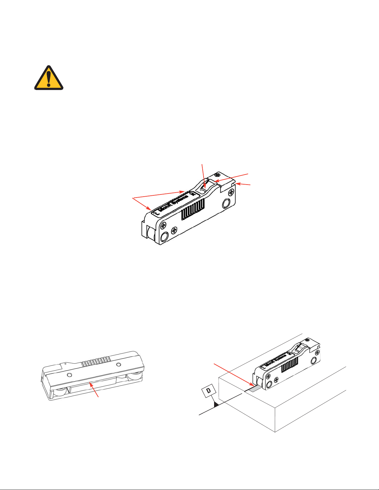
Installation by Hand Grip Applicator Tool
Reference arrows for Tool and
tape scale orientation
1.
OPS Top Mounted Tape Scale Applicator Tool (Model Number: TSAT-PPT)
The Hand Grip Applicator Tool is needed for tape scale lengths greater than 300mm. It is designed to be hand
held and to slide along either a permanent or temporary mounting edge while tape scale is applied.
Tape scale entry channel
2.
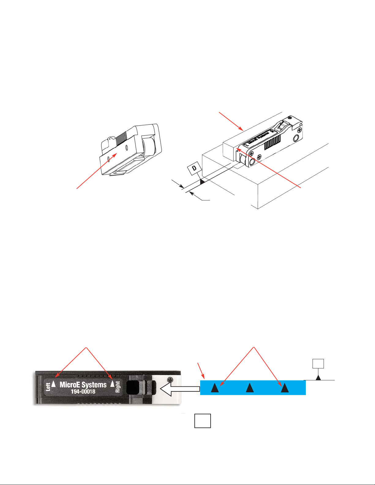
Hand Grip Applicator Tool mounting surface guide edges.
The had grip applicator tool has two guide edges. One is for low guide edge configurations of thickness 0.76mm
(0.030 inches) and one for higher guide edge configurations of thickness greater than 9.5mm (.375 inches).
Refer to the OPS interface drawing for tape scale reference edge “D”
Low guide edge of tool. Mounting
surface edge of thickness 0.76mm
(0.030 inches)
Note: The low guide edge also corresponds to the “D” tape
scale reference edge in the interface drawing.
Low guide edge
D
Low guide edge
NOTE:
For best system performance, talc-free gloves or finger cots should be worn during all steps
of tape scale installation.
Thoroughly clean the scale mounting surface and reference edge using a cotton swab or
lint-free cloth dampened with isopropyl alcohol or acetone. Remove all dust and particles.
Adhesive backing channel
Adhesive backing exit
Page 20
Page 20
Tape Scale, OPS Top Mount Configuration
Installation by Hand Grip Applicator Tool
2.
Hand Grip Applicator Tool mounting surface guide edges (continued)
Higher guide surface of tool. Mounting
surface reference edge is higher than
9.5mm (0.375 inches)
Higher guide edge surface
Temporary straight edge
Guide surface
D
4.18 ± 0.05mm
D
= Tape Scale Mounting Surface Reference Edge
(See the OPS interface drawings)
3.
Orienting the Hand Grip Applicator Tool and PurePrecision II Tape Scale
Both Tape Scale arrows, and Applicator Tool orientation arrows need to point in the same direction for
proper orientation.
Also note, the “D” reference edge in the OPS interface drawing. The tape scale orientation arrows always
point to the “D” reference edge. In the example below, the “D” reference edge is shown, with tape scale
orientation arrows pointing to it. The applicator tool orientation arrows are also pointing in the same
direction.
In the example shown below, the left side of the tape scale will need to go into the applicator tool entry
channel first. This tape scale end is referred to as the “correct” end.
Applicator Tool orientation arrows
Tape Scale orientation arrows on blue protective film
Left side of tape scale
D
Page 21
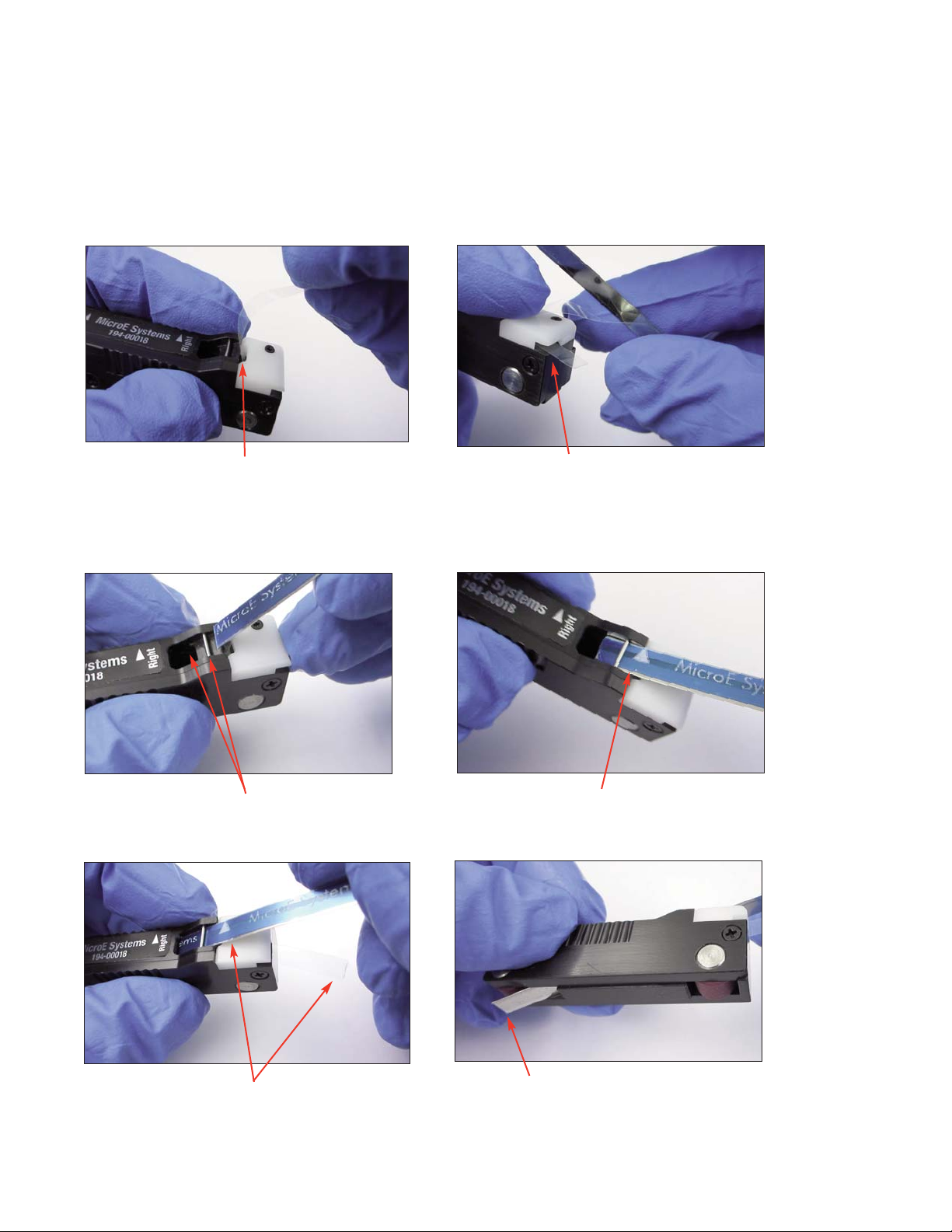
4.
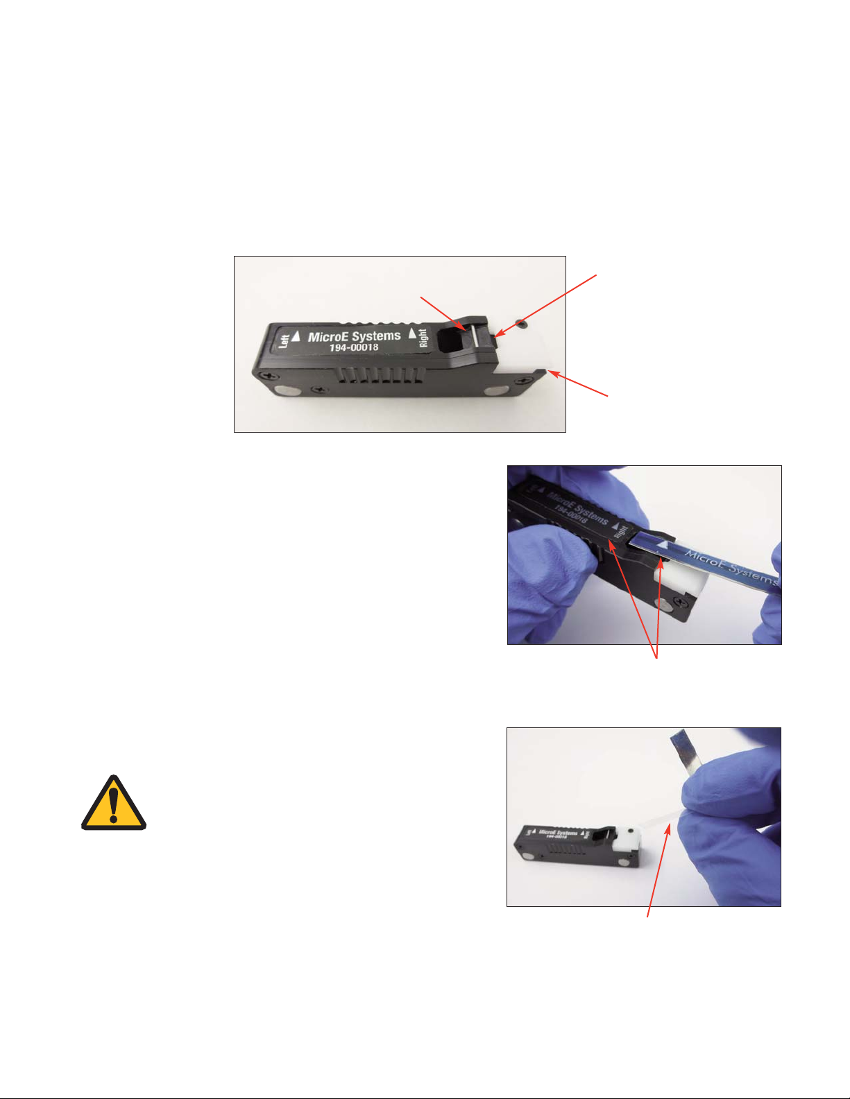
Preparing the tape scale for the applicator tool
PurePrecision Tape Scales have 3 layers, blue protective film, steel scale, and adhesive backing. The top two
layers fit under the dowel pin, while the bottom adhesive backing fits into the backing slot as shown below.
Page 21
Tape Scale, OPS Top Mount Configuration
Installation by Hand Grip Applicator Tool
Entry slot for tape scale with blue
protective film (under dowel pin)
Entry slot for adhesive
backing
Exit slot for adhesive
backing
Determine the “correct” end of the tape scale to insert
into the applicator tool entry slot. The correct end is
determined by the direction of the orientation arrows on
both the tape scale blue protective film and the
applicator tool arrows. Both sets of arrows have to point
in the same direction.
There are different methods to prepare and insert the
tape scale and backing into the hand grip applicator tool
slots. One method is shown below.
From the “correct” end of the tape scale, peel and curl
back 50-75mm (2-3 inches) of the adhesive liner as
shown. Take care not to touch the adhesive on the
bottom of the tape scale or allow any particle
contamination.
“Correct” tape scale end. All orientation
arrows point in the same direction.
NOTE:
Do not peel the blue protective film off
at this time.
Peel and curl back 50-75mm (2-3
inches) of the adhesive liner
Page 22
Page 22
5.
Feed the adhesive backing into the applicator tool
Insert the backing film into the applicator tool.
Tape Scale, OPS Top Mount Configuration
Installation by Hand Grip Applicator Tool
6.
Tape Scale Insertion
Insert the tape scale (with blue protective film) under the dowel pin, into the entry slot as shown.
Feed tape scale into the applicator tool, until the end of the tape is past the front roller as shown.
6.4 Tape scale fed past front tool roller.
5.2 Adhesive backer exiting from backer slot.
5.1 Adhesive backer inserted into backer slot.
6.1 Dowel pin and entry slot. 6.2 Tape inserted.
6.3 Tape inserted with adhesive backing exiting.
Page 23
Page 23
Tape Scale, OPS Top Mount Configuration
Installation by Hand Grip Applicator Tool
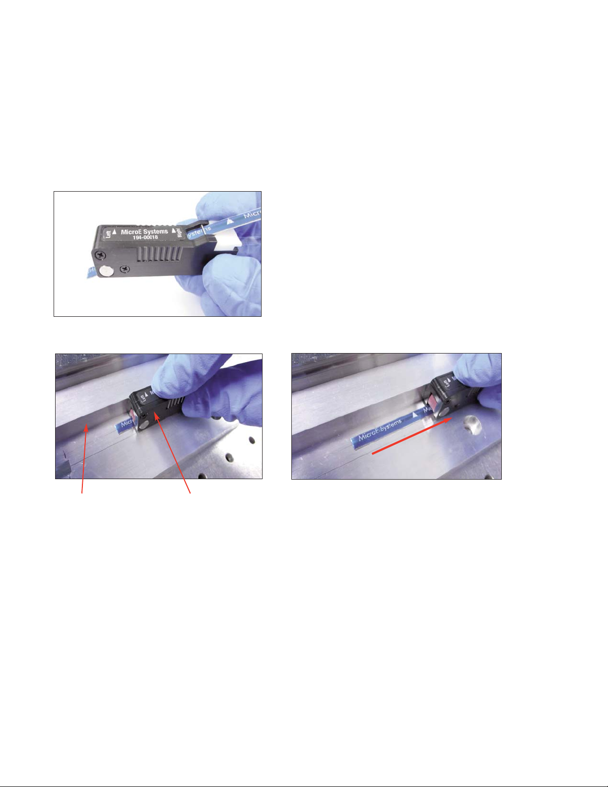
7.
Applying tape scale with the hand grip applicator tool
Once the applicator tool is configured with the adhesive backer exiting from the exit slot and steel tape
extending past the front tool roller, the scale is ready to be installed on the mounting surface.
Applicator tool correctly
configured for installation.
High guide edge face. Applicator tool pressed
down and against high
guide edge face.
Slide tool along guide edge face with a slow even pressure motion until all of the tape is installed on
the mounting surface.
Be sure the adhesive backing film does not bunch up and jam inside the tool and exits freely from
the exit slot.
Applicator tool in motion against guide
edge face.
Page 24
Page 24
Tape Scale, OPS Top Mount Configuration
Installation by Hand Grip Applicator Tool
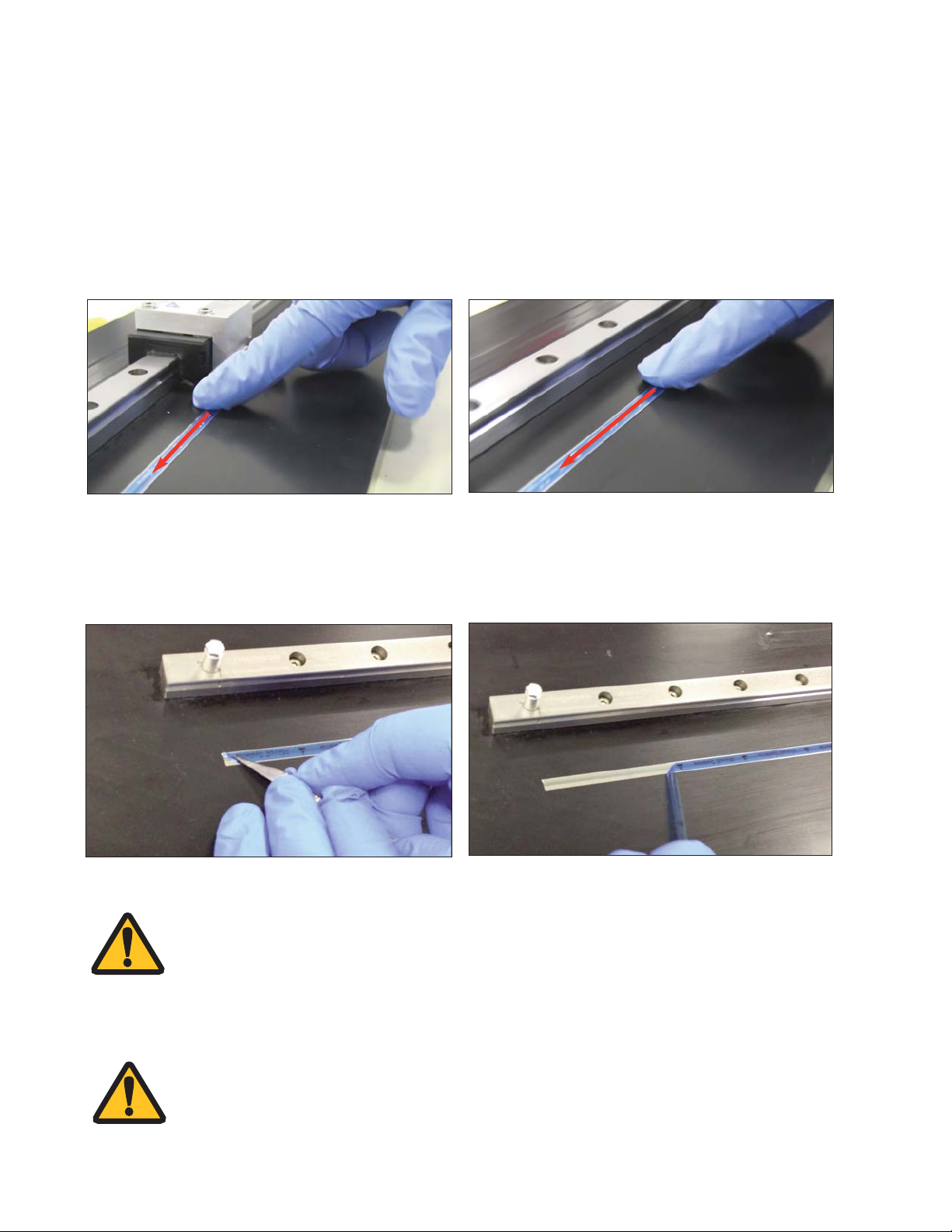
8.
Once the scale is applied to the mounting surface, and before the blue protective film is removed, it is
recommended that even pressure be applied over the entire tape scale length by sliding a glove or cot
protected finger across the scale. The applied pressure will ensure that the adhesive is evenly and
permanently set.
NOTE:
After removing the blue protective film, the scale is ready for use and will
perform to specification.
The encoder will not function properly with the blue protective film installed.
It must be removed for proper encoder operation .
9.
Peel off the blue protective film.
Start the peeling process using a sharp tool, being careful not to damage the scale. Pull off the remaining
blue protective film. Clean the tape scale using alcohol or acetone and a lint-free cotton cloth.
NOTE:
If installing index/limits (Laser Tape II and PVGL
glass), go to the “Stick-On Index and Limit
Marker Installation” section.
Page 25
Page 25
Linear Glass Scales, OPS Side and Top Mount
Configurations
Installation
1.
Mounting Surface Preparation
Inspect the mounting surface for any machining irregularities. MicroE Systems recommends a surface finish of
better than 1.6 micrometers Ra and mounting surface flatness of 0.0001 inch/inch.
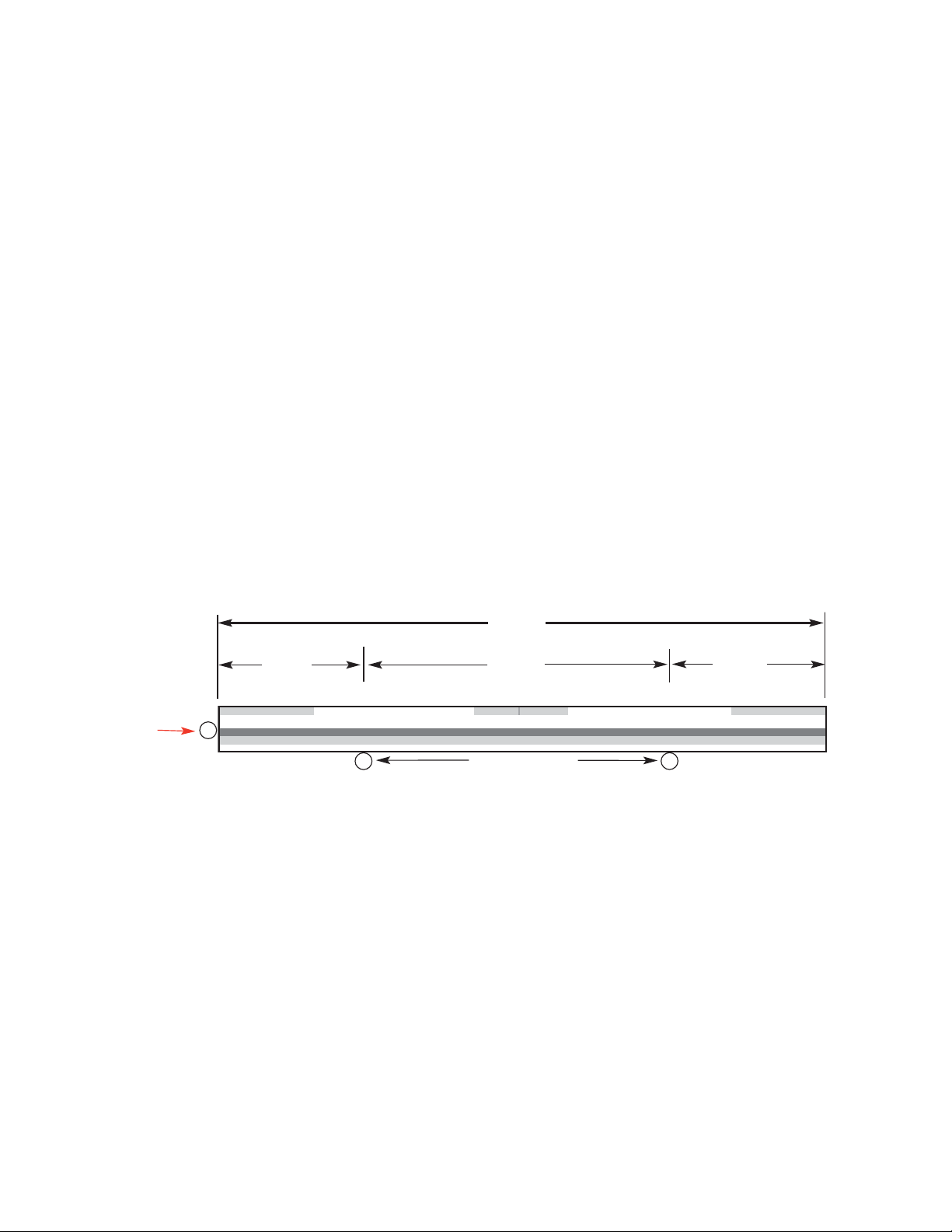
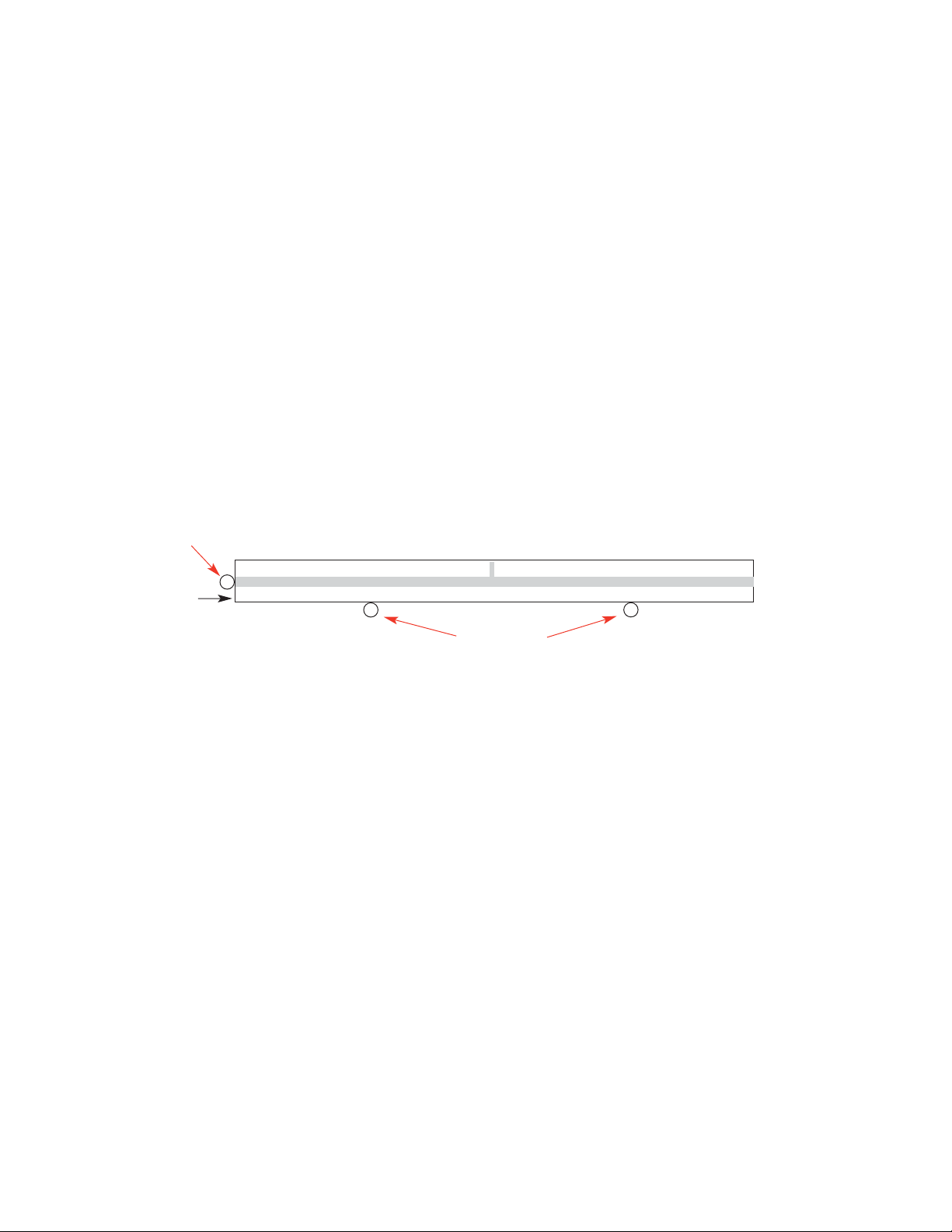
MicroE Systems
0.2L
0.6L
0.2L
Benching Pins
End
Benching
Pin (optional)
L
2.
“Benching” the linear Scale
MicroE Systems' linear glass scales should be permanently affixed to the mounting surface, using epoxy and
the adhesive attached to the back of the scale.
"Benching" the glass scale to the system means aligning the scale by means of benching pins. Refer to the
OPS Interface Drawings for dimensions. The “benching” pins can be set up on either side of the glass scale,
but are referenced to the “D” reference edge of the glass scale as shown in the Interface Drawing.
Be sure to use the proper orientation for the “D” linear glass scale reference edge and the OPS Top Mount
reference face “B” as shown in the OPS Interface Drawings.
Two benching pins are recommended on either long side of the glass scale and one at either end.
Position the benching pins inward from either end of the scale. 20% of the overall scale length is the
recommended location from the edge.
Be sure the benching pins do not exceed the height of the linear glass scale to prevent mechanical interference
with the sensor or sensor mount.
Glass Scale “Benching” Diagram
Page 26
Page 26
Linear Glass Scales, OPS Top Mount Configurations
Installation
3.
Mounting linear Glass Scales (with adhesive backing), Model Number PVGL-T
Make sure that the mounting surface is dry and clean.
Align the scale by placing the edges against the benching pins.
Peel off the glass scale adhesive backing and press into place.
Apply a hard epoxy, such as Tra-Con’s Tra-Bond 2116, to the one end of the scale (at the end benching pin
side, if an end benching pin is used).
Using one end secured with hard epoxy, allows thermal expansion from the benched end of the scale.
Allow the adhesives to fully cure. A cure time of 12 hours is required for the glass scale's pressure sensitive
adhesive to achieve the best performance and reliability.
End Benching
Pin
Hard epoxy
at one corner,
end benching
pin end side
only.
MicroE Systems
Benching pins
Glass Scale with Adhesive Backing
Page 27

Page 27
Index and Limit Marker “Strip” Packaging
Index and Limit Marker Installation
Stick-On Markers for PurePrecision Laser Tape II (HPTS-) and Performance and Value Linear
Glass (PVGL-). (Not applicable to PurePrecision Marker Tape II Scales)
Index Marker Strips, Model Number NRIMS
Limit Marker Strips, Model Number NRLMS
Index Strip: 8 Index Markers
Limits Strip: 4-Left and 4-Right*
4-Left
4-Right
*Limit markers have different reflectivity
values for left and right markers.
Stick-On Index and Limit Markers, Part Numbers
Page 28
Page 28
Index and Limit Marker Installation
Stick-On Markers for PurePrecision Laser Tape II (HPTS-) and Performance and Value Linear
Glass (PVGL-). (Not applicable to PurePrecision Marker Tape II Scales)
1.
Put on finger cots or gloves before starting the
index and limit markers installation.
NOTE:
Before installing the Limit and Index
Markers, make sure that the blue
protective film from the PurePrecision
Tape Scale has been removed.
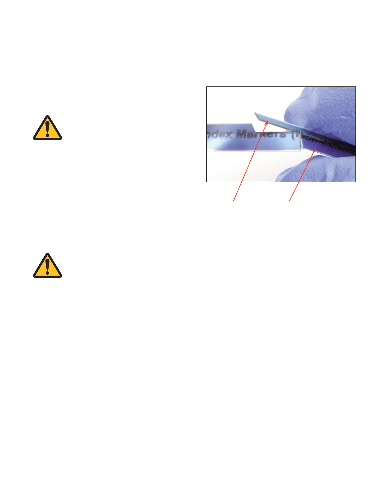
Begin by holding the Limit and Index Marker strip so
that the blue protective film is on top and the reflective
surface is at the bottom.
Remove the marker from a perforated strip by gently
twisting the strip in the area of the marker.
The marker will pull away from the transparent
adhesive liner. Holding only the handle section, slowly
pull the index marker from the perforated sheet. This
will expose the adhesive.
NOTE:
Be sure to hold the Index or Limit Markers
by the handle only. The adhesive on the
handle section can be touched. However,
be careful not to touch the adhesive on
the areas of the markers that will be
applied to the scale.
Handle sectionStick-on Index
Page 29
Page 29
Index and Limit Marker Installation
Stick-On Markers for PurePrecision Laser Tape II (HPTS-) and Performance and Value
Linear Glass (PVGL-). (Not applicable to PurePrecision Marker Tape II Scales)
2.
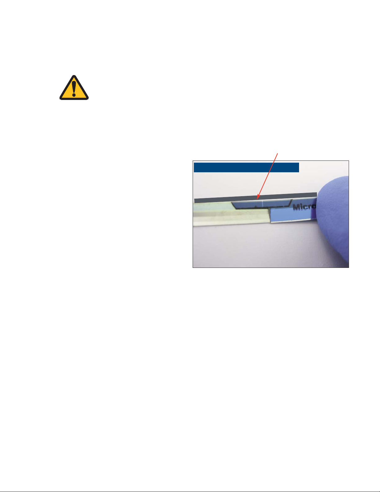
Attaching the Index Marker to
the Scale
Place the top edge of the marker against the
benching edge, holding it at a 45° degree
angle as shown in the photo. This keeps the
adhesive away from the scale, until the
marker is the correct location, before being
pressed into place.
If the scale is installed with an offset from its
reference edge, a temporary reference edge
surface such as a small metal block must be
used for the index and limit markers.
When the marker is tight against the
reference edge, press the marker onto the
scale with your finger.
Benching edge (“D” reference edge)
Index Marker
USE FINGER COTS or Gloves
NOTE:
Be sure to remove the blue protective film from the top of the tape scales
before applying stick-on index and limit markers.
For benching edge requirements, refer to the Interface Drawings for
OPS. The benching edge corresponds to the “D” reference edge in the
interface drawings.
Page 30
Page 30
Index and Limit Marker Installation
Stick-On Markers for PurePrecision Laser Tape II (HPTS-) and Performance and Value Linear
Glass (PVGL-). (Not applicable to PurePrecision Marker Tape II Scales)
3.
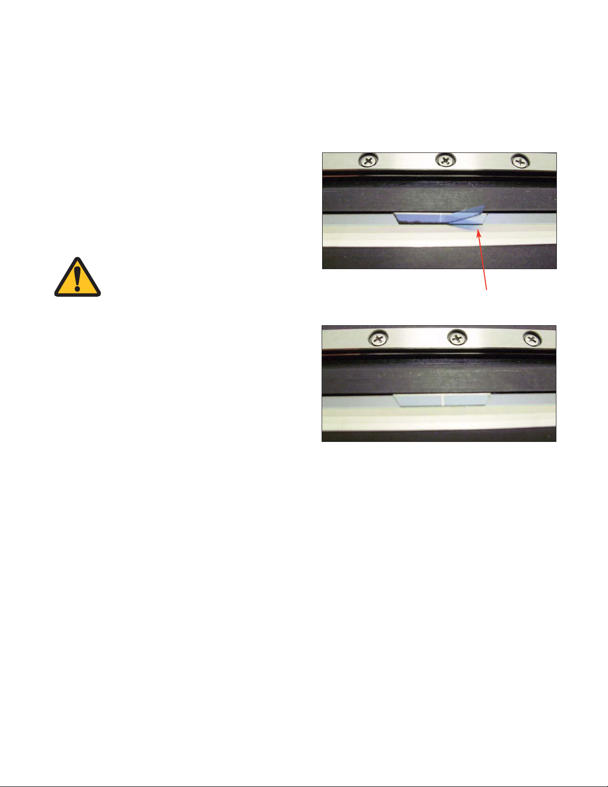
Press your finger on the marker close to the
edge of the handle. Then, with your other hand,
pull up on the handle to detach it from the
marker. The handle will break away from the
marker.
Carefully remove the blue protective film from the
marker surface.
NOTE:
Use fingernails or plastic tweezers
to remove the blue protective film,
but do not use a hard metal object.
Using a hard metal object might
damage the grating on the
PurePrecision Tape Scale.
4.
Apply the left and right limit markers, if applicable.
Repeat steps 1-3.
Peel blue protective film
Stick-on marker installed
Page 31
Page 31
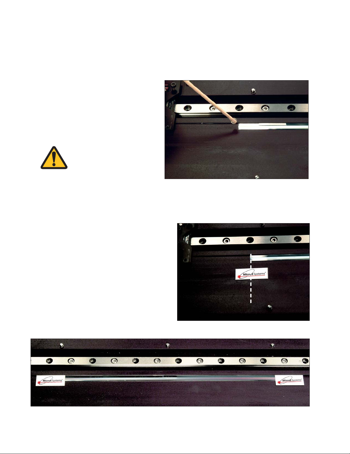
End Cap Installation for Tape Scales
Optional
1.
Epoxy Setup
• Mix the two-part epoxy and place it in a
syringe or on the end of a stick. Do not
use a cotton swab to apply the epoxy.
• Put epoxy on the end of the scale. Make
sure that the epoxy touches both the
mounting surface and the scale across
the width of the scale.
Only apply epoxy at the
ends of the tape scale. Do
not get any epoxy on the
tape scale in the
measuring area.
• Perform Step 2, immediately while the
epoxy is still in a liquid state.
2.
Installing the End Caps on the
Mounting Surface
• Remove the adhesive liner from end cap.
• Place the end cap on the top of the scale and
epoxy so that the end of the scale is in the
middle of the end cap.
• Press down lightly to ensure adhesion and
let cure for 24 hours.
Page 32

Page 32
Final Cleaning, Inspection and Cure Time
Before using the encoder for servo control, clean the tape scale, index marker and limit markers using alcohol
or acetone and a lint-free cotton cloth or swab. Finally, inspect the tape scale's surface for scratches, adhesive
spots or smears in the measuring length.
A cure time of 12 hours is required for the tape scale's pressure sensitive adhesive to achieve the best
performance and reliability.
Reworking to Correct Mistakes
Once installed, the tape scale, the index marker, and the limit markers cannot be moved or removed and
reinstalled. Reworking will require removal and discarding of the old tape or markers, and installation of
new ones.
If only the index or limit markers have to be replaced, the scale can remain in place and be reused so long as
there is no damage to the scale’s surface. Do not use a tool made of metal or other hard material to remove
the markers. Clean the scale’s surface completely of any adhesive residue before applying new markers.
Page 33

Page 33
Contacting MicroE
MicroE Systems is a world leader in optical encoder technology with
offices in major industrial centers around the globe.
To learn more about MicroE Systems products, visit:
www.microesystems.com.
Our products have been used by thousands of companies worldwide to
solve a wide range of motion control applications. Our advanced
encoder technology and application expertise has driven innovations in
the design of machinery, equipment and instrumentation in many
industries, including medical, industrial, robotics, automation, metrology,
semiconductor manufacturing, packaging equipment, entertainment,
energy, military, and scientific research.
MicroE Systems
125 Middlesex Turnpike
Bedford, MA 01730 USA
T 781-266-5700
F 781-266-5112
[email protected]
www.microesystems.com
© 2015 MicroE Systems
 Loading...