

Page 1
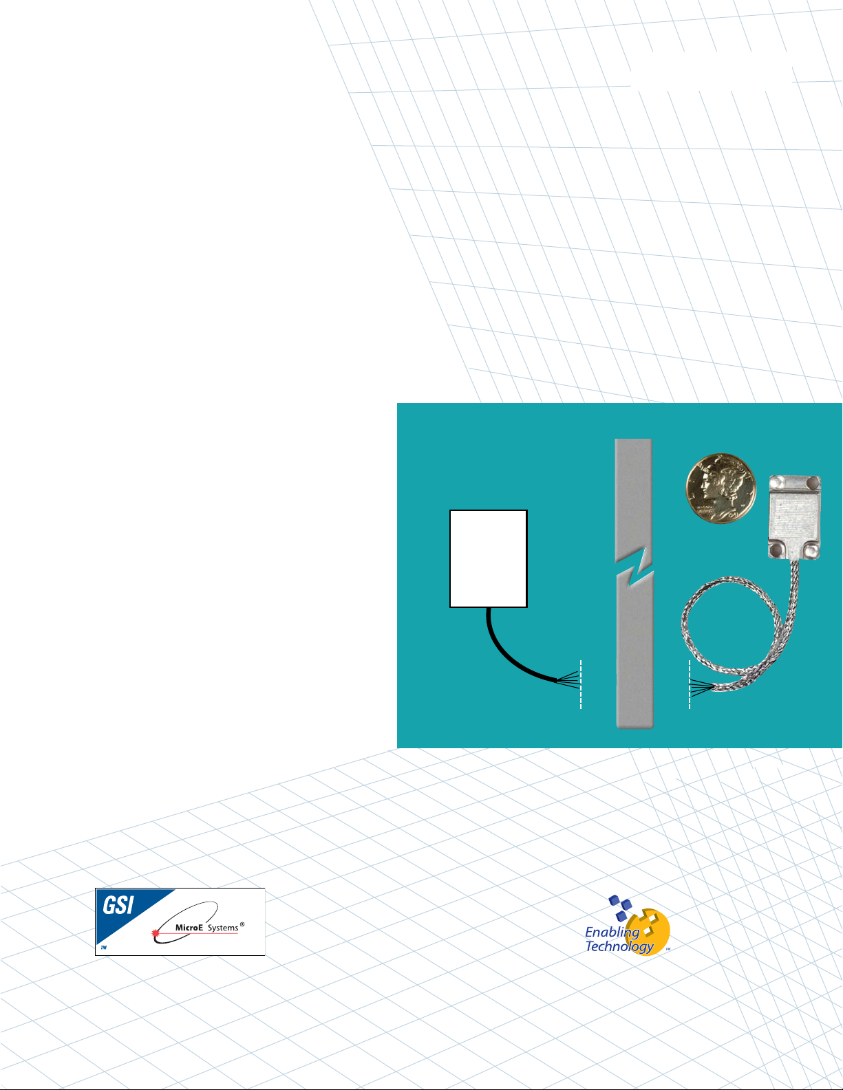
Mercury™1500V - Vacuum Rated
DDiiggiittaall OOuuttppuutt EEnnccooddeerr SSyysstteemm
IInnssttaallllaattiioonn MMaannuuaall
aanndd RReeffeerreennccee GGuuiiddee
Vacuum Wall
Customer
Controller
Preliminary 8/20/2008
Manual No. IM-M1500V Rev S7
Page 2

IInnttrroodduuccttiioonn
MicroE Systems was founded to advance encoder technology to
a level never before achieved. Our objective was to design encoder
systems that would be small enough to fit into densely packed OEM
equipment designs, affordable enough for cost-sensitive applications
and easy enough to enable installation, setup and alignment by
assemblers with little training. We are pleased to say that all of
these goals have been realized with the introduction of the Mercury
family of encoders.
Sensor shown
actual size
M10
PPaatteennttss
Covered by the following patents: US 5,991,249; EP 895,239; JP 3,025,237; US
6,897,435; and EP 1,451,933. Additional patents and patents pending may apply.
PPrreeccaauuttiioonnss
Follow standard ESD precautions. Turn power off before connecting the sensor.
Do not touch the electrical pins without static protection such as a grounded
wrist strap.
Do not touch the glass scale unless you are wearing talc-free gloves or finger
cots. Please read this installation manual for full instructions.
LLAASSEERR SSAAFFEETTYY IINNFFOORRMMAATTIIOONN::
MMeerrccuurryy && CChhiippEEnnccooddeerr
1
2
This product is sold solely for use as a component (or replacement) in an electronic product; therefore it is not
required to, and does not comply with, 21 CFR 1040.10 and 1040.11 which pertain to complete laser
products. The manufacturer of the complete system-level electronic product is responsible for complying with 21
CFR 1040.10 and 1040.11 and for providing the user with all necessary safety warnings and information.
MicroE encoders contain an infrared laser diode or diodes. Emitted invisible laser radiation levels have been
measured to be within the CDRH Class 1 range, which is not considered hazardous; however, to minimize
exposure to the diverging beam, the encoder sensor should be installed in its operational configuration in close
proximity to the encoder scale before power is applied.
• Invisible laser radiation; wavelength: 850 nm
• Max power 2.4 mW CW (4.8 mW CW for Mercury II™)
• CAUTION – The use of optical instruments with this product will increase eye hazard. DO NOT VIEW
DIRECTLY WITH OPTICAL INSTRUMENTS (MICROSCOPES, EYE LOUPES OR MAGNIFIERS).
• All maintenance procedures such as cleaning must be performed with the MicroE encoder turned off.
• Do not insert any reflective surface into the beam path when the encoder is powered.
• Do not attempt to service the MicroE encoder.
INVISIBLE LASER RADIATION
DO NOT VIEW DIRECTLY WITH OPTICAL
INSTRUMENTS
(MICROSCOPES, EYE LOUPES OR
MAGNIFIERS)
Page 3

Page 1
TTaabbllee ooff CCoonntteennttss
SYSTEM ILLUSTRATION PAGE
Encoder with Linear scale 2
Encoder with Rotary scale 3
INSTALLATION INSTRUCTIONS
Using SmartPrecision Alignment Tool - Linear Scales
Mounting Encoder System 4
Alignment of Encoder System 5
Using SIN/COS Signals - Linear Scales
Mounting Encoder System 6
Alignment of Encoder System 7
Establishing an Index 7
Using SmartPrecision Alignment Tool - Rotary Scales
Mounting Encoder System 8
Alignment of Encoder System 9
Using SIN/COS Signals - Rotary Scales
Mounting Encoder System 10
Alignment of Encoder System 11
Establishing an Index 11
REFERENCE SECTION
Installation of Linear Scales 12
Grounding Instructions 13
Recommendations for Power 13
Customer Interface Cable Requirements 14
Output Signal description 15
ENCODER TROUBLESHOOTING
Selected Topics 16
Cleaning Scales 16
Contact MicroE Systems Back Cover
Page 4
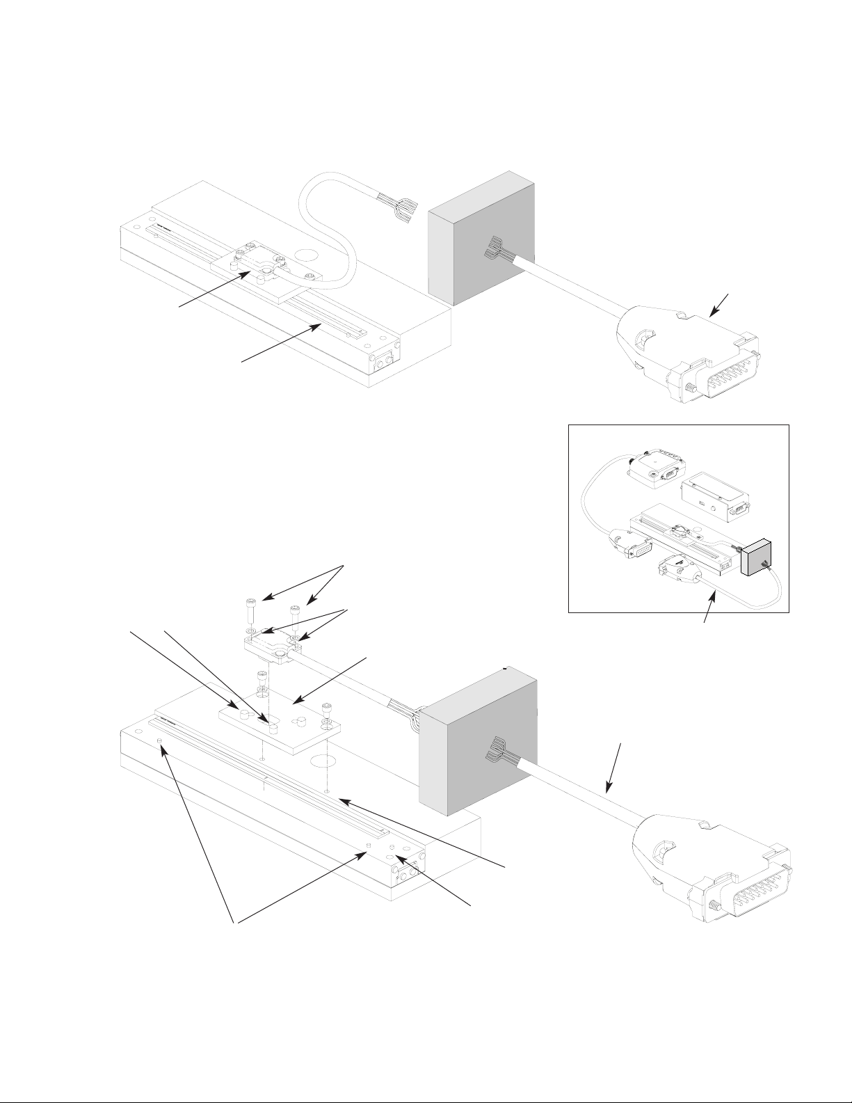
15 pin standard D-sub connector
MercuryTM1500V Encoder System
with Linear scale
EExxppaannddeedd VViieeww
End locator pin
Mounting screws & flat washers (2
needed per screw)
Bracket mounting holes (2)
Optional sensor benching pins (3)
Typical user-supplied
sensor mounting bracket
SSyysstteemm VViieeww
Shown with linear scale
Page 2
Scale reference datum;
example shown with benching pins
SmartPrecision Alignment Tool SSAT1500-V
Sensor mounting holes (2)
Sensor
Linear glass scale
(shown mounted on a linear slide)
Vacuum wall
Vacuum wall
Double shielded cable
Atmospheric Cable
Page 5
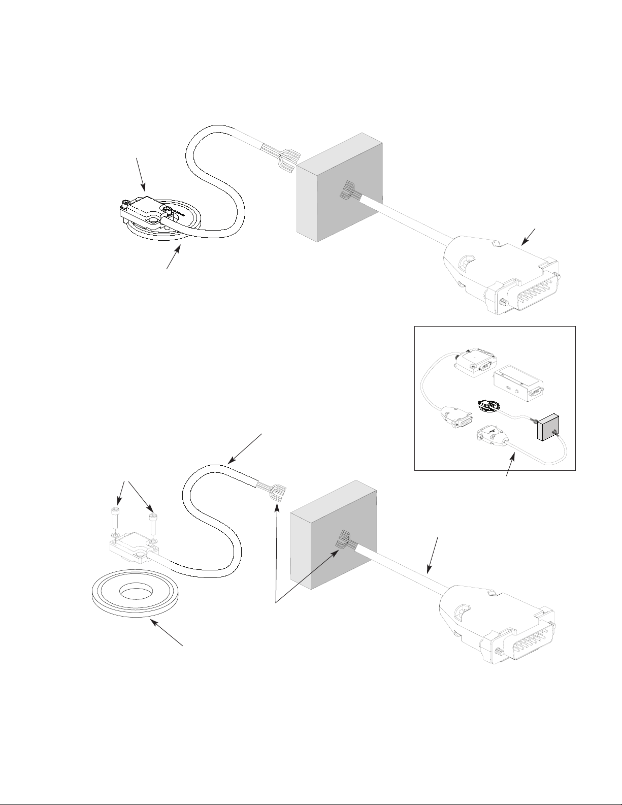
sensor
Mercury 1500V Encoder System
with Rotary scale
EExxppaannddeedd VViieeww
Top reflective rotary scale
Rotary glass scale
Page 3
Mounting screws & flat
washers (2 needed per screw)
SSyysstteemm VViieeww
Shown with rotary scale
Vacuum compatable cable
Flying leads
Vacuum wall
SmartPrecision Alignment Tool SSAT1500-V
Vacuum wall
15 pin standard D-sub connector
Atmospheric Cable
Double shielded cable
Page 6
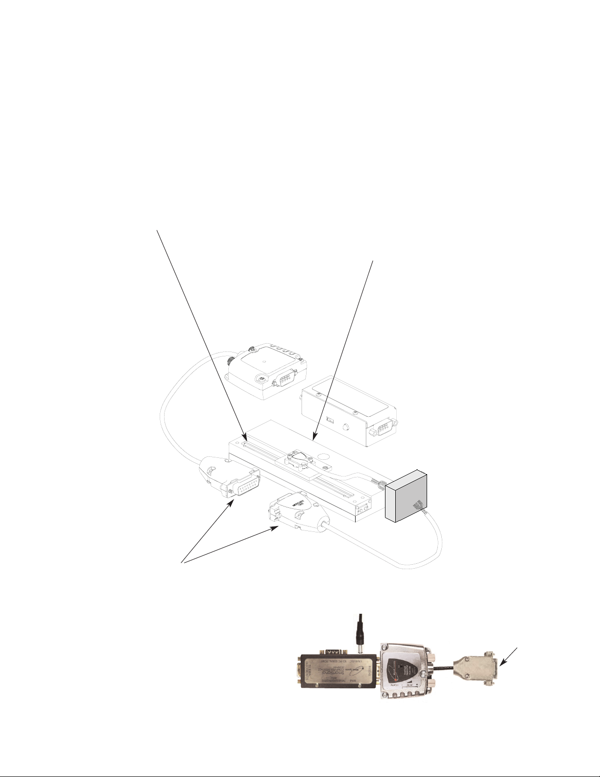
Installation Instructions
Linear Encoders - Using Alignment Tool - Mounting
1
2
Attach the scale to the base slide. Reference the preferred
datum on the interface drawing for either end or center
index orientation.
Depending on the mounting method, attach the scale
to the slide with adhesive. Refer to pg. 12 for details.
Be sure the grating surface of the scale faces the sensor.
Insure that there is no contact between these surfaces or
damage may result.
Be sure the source power is off before
connecting the SmartPrecisionTMII Alignment Tool.
Connect the M1500V to the SmartPrecision II
Alignment Tool. (The M1500V-AC Atmospheric
Cable shown in the illustration above is optional.
A customer-supplied cable may be used.)
3
Page 4
To M1500V encoder
To Power Supply
4
Connect the Alignment Tool to the
Computer Interface Adapter. Turn on
the power.
Install the sensor on your mounting surface
referencing the appropriate datum surface as
shown on the interface drawing. Use 2 washers
per mounting screw.
Benching pins may be used to locate the sensor
if the system mechanical tolerances are adequate.
See data sheet for alignment tolerances, or keep
mounting screws loose for sensor alignment if
benching pins are not used.
Page 7
Installation Instructions
Linear Encoders - Using Alignment Tool - Alignment
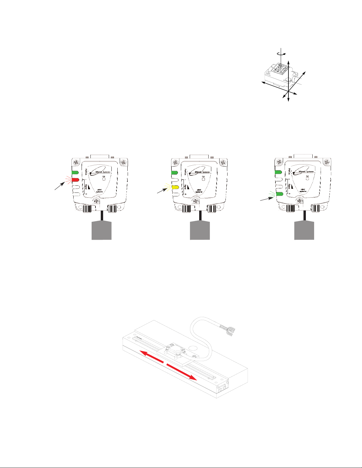
Proper sensor alignment may require minor adjustments to the sensor position with
respect to the scale. This can be performed easily using the SmartPrecision Alignment
Tool as illustrated below.
The red, yellow, or green LED will light depending on sensor alignment. Slowly
move the sensor by allowing it to slide on the mounting surface until the green
LED, is illuminated. Optimal alignment will be displayed as a “Bright Green” LED.
IIMMPPOORRTTAANNTT
: Confirm that the green LED blinks when passing over the index.
If not, readjust the sensor in the Y direction and repeat the above procedure.
When alignment is completed, tighten the sensor mounting screws.
6
5
Confirm green over the full range of motion by sliding
the scale past the sensor. The “green” LED must
remain on over the entire range. If not aligned over the
entire range of motion, loosen the sensor mounting
screws and repeat step 5.
x
Y
Z
θ
z
To align the sensor, move
it in the Y or θ
z
direc-
tions.
Page 5
SmartPrecision
Alignment Tool
Improper
Alignment LED
Red
Power/
Calibration
Power/
Calibration
Power/
Calibration
Improved
Alignment LED
Yellow
Proper
Alignment LED
Green
Optimal
Alignment LED
Bright Green
15 pin D
connector
to sensor
15 pin D
connector
to sensor
15 pin D
connector
to sensor
SmartPrecision
Alignment Tool
SSAT1000
SmartPrecision
Alignment Tool
SSAT1000
SmartPrecision
Alignment Tool
SSAT1000
Page 8
Page 6
2
3
Be sure power is off before
connecting the sensor.
Connect the M1500V to your
interface electronics using
the wire color/signal
assigments described on the
interface drawing.
Tighten the connector screws.
Power up the system.
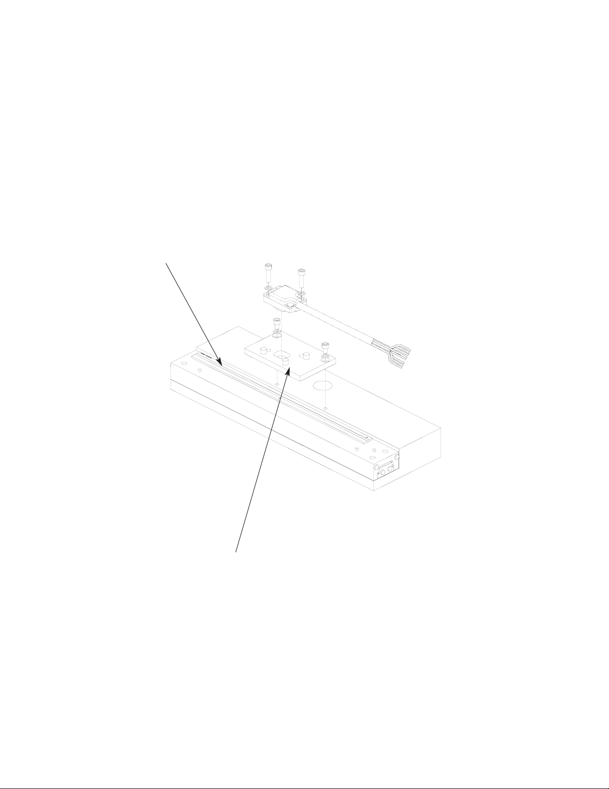
Install the sensor on your mounting surface
referencing the appropriate datum surface as
shown on the interface drawing. Use 2 washers
per mounting screw.
Benching pins may be used to locate the sensor
if the system mechanical tolerances are adequate.
See data sheet for alignment tolerances, or keep
mounting screws loose for sensor alignment if
benching pins are not used.
Installation Instructions
Linear Encoders - Using Sin/Cos Signals - Mounting
1
Attach the scale to the base slide. Reference the
preferred datum on the interface drawing for
either end or center index orientation.
Depending on the mounting method, attach the
scale to the slide with adhesive. Refer to
pg. 12 for details.
Be sure the grating surface of the scale faces the
sensor. Insure that there is no contact between
these surfaces or damage may result.
Page 9
Page 7
4
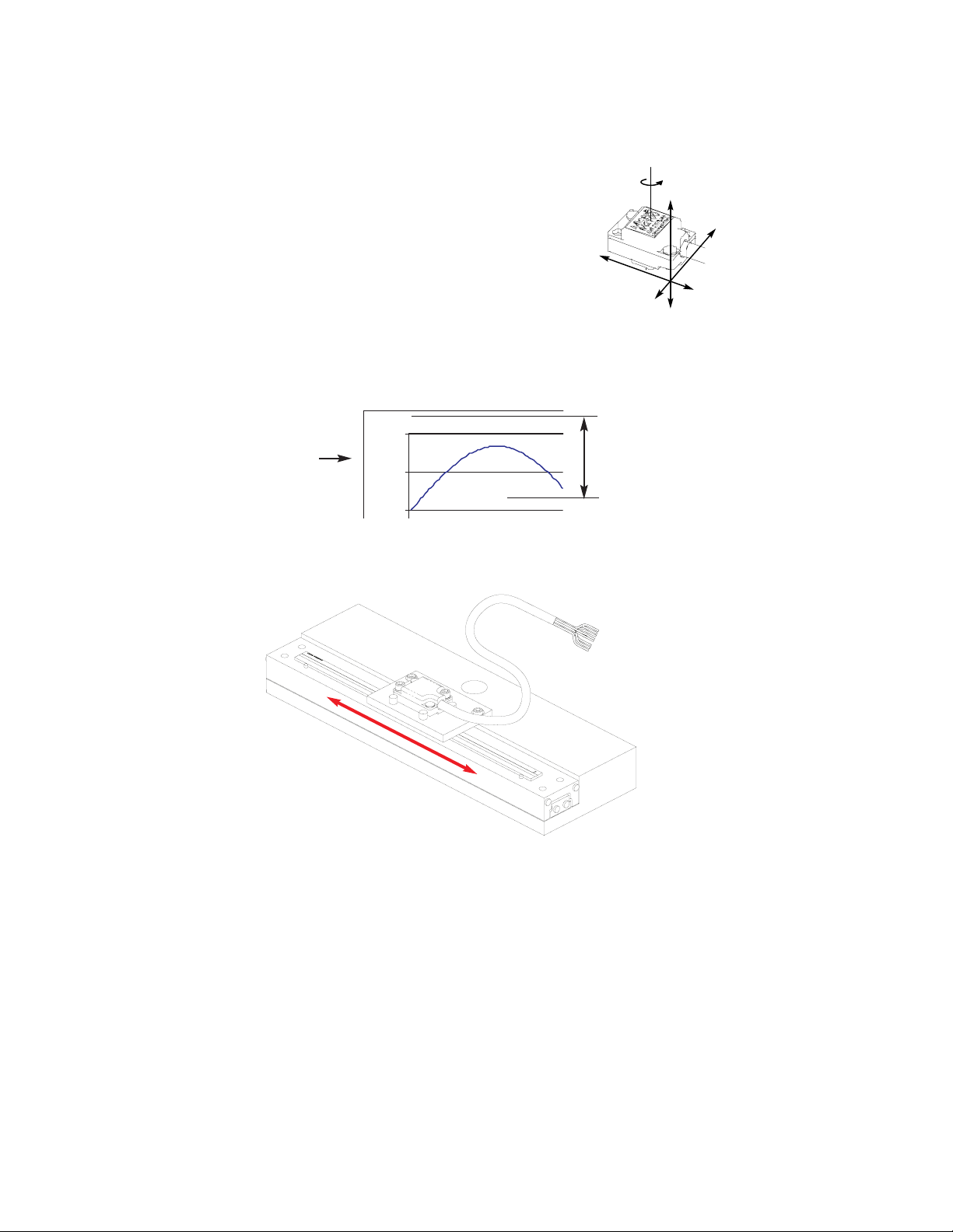
INDEX TRACK ALIGNMENT
The M1500V must be aligned for both the main and index tracks.
When properly aligned, the sensor will produce an index window as
the sensor passes over the index mark. The index window is
approximately one fringe wide (20µm). To verify proper index track
alignment, use a digital oscilloscope triggered on the index window.
Refer to the interface drawing for the index window pinout.
Confirm proper alignment of the main track over the full range of
motion. If not aligned over the entire range of motion, loosen the
sensor mounting screws and repeat steps 4 and 5.
5
MAIN TRACK ALIGNMENT
If benching dimensions cannot be provided, proper
sensor alignment may require minor adjustments
to the sensor position with respect to the scale.
This can be performed by maximizing the sine
signal from the M1500V.
Using an oscilloscope, monitor the sine or cosine signal (refer to
the interface drawing for pinouts) while moving the sensor over
the scale. Align the sensor until 0.8 volts peak-to-peak +/- 25%
is obtained. When alignment is completed, tighten the sensor
mounting screws (0.37Nm [3.3 inch-lbs.] maximum torque).
x
Y
Z
θ
z
To align the sensor, move
it in the Y or θz directions.
0
0.6
1.2
0.8 V
pp
Installation Instructions
Linear Encoders - Using Sin/Cos Signals - Alignment
1.7 V offset
(nominal)
Page 10
Installation Instructions
Rotary Encoders - Using Alignment Tool - Mounting
Attach your hub/scale
assembly to the rotary
device. Refer to the
interface drawing. The
reflective surface of the
scale must face the sensor.
1
Page 8
3
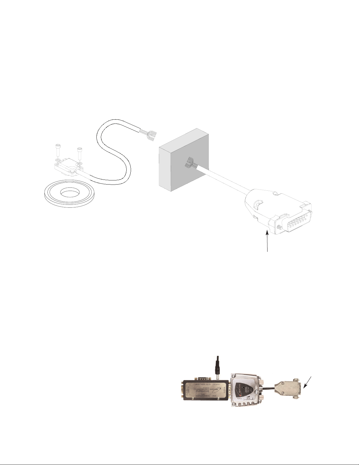
Be sure the source power is off
before connecting the SmartPrecision
Alignment Tool. (The M1500V-AC
Atmospheric Cable shown above is
optional. A customer-supplied cable
may be used.)
Connect the M1500V encoder to the
SmartPrecision Alignment Tool.
2
To M1500V encoder
To Power Supply
4
Connect the Alignment Tool to the
Computer Interface Adapter. Turn on
the power.
Install the sensor on your mounting surface
referencing the appropriate datum surface as
shown on the interface drawing. Use 2 washers
per mounting screw.
Benching pins may be used to locate the sensor
if the system mechanical tolerances are adequate.
See data sheet for alignment tolerances, or keep
mounting screws loose for sensor alignment if
benching pins are not used.
Page 11
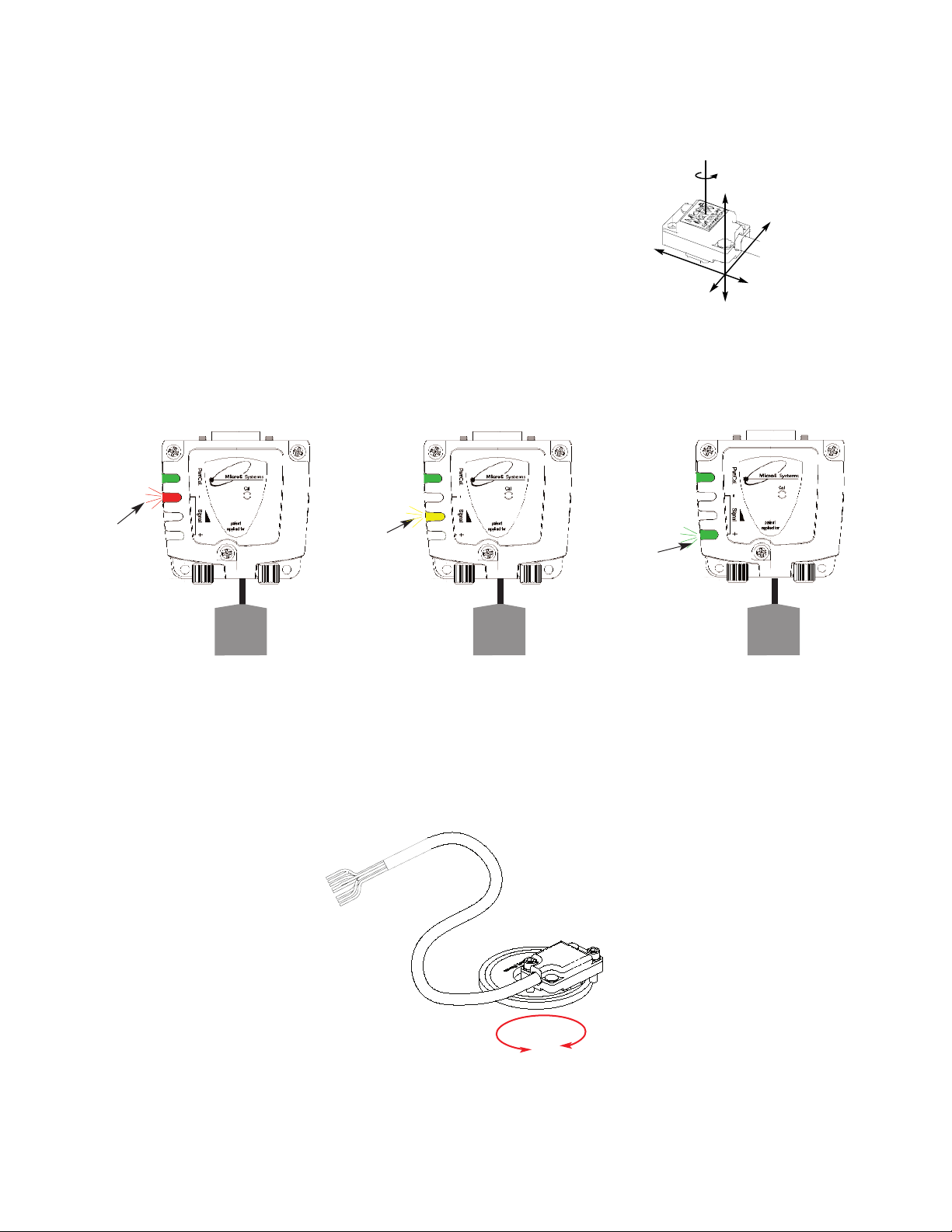
Installation Instructions
Rotary Encoders - Using Alignment Tool - Alignment
Page 9
5
Proper sensor alignment may require minor adjustments to the sensor position with
respect to the scale. This can be performed easily using the SmartPrecision Alignment
Tool as illustrated below.
The red, yellow, or green LED will light depending on sensor alignment. Slowly
move the sensor by allowing it to slide on the mounting surface until the green
LED, is illuminated. Optimal alignment will be displayed as a “Bright Green” LED.
IIMMPPOORRTTAANNTT
: Confirm that the green LED blinks when passing over
the index. If not, readjust the sensor in the Y direction and repeat the above
procedure. When alignment is completed, tighten the sensor mounting screws.
x
Y
Z
θ
z
To align the sensor, move it
in the Y or θz directions.
6
SmartPrecision
Alignment Tool
Improper
Alignment LED
Red
Power/
Calibration
Power/
Calibration
Power/
Calibration
Improved
Alignment LED
Yellow
Proper
Alignment LED
Green
Optimal
Alignment LED
Bright Green
15 pin D
connector
to sensor
15 pin D
connector
to sensor
15 pin D
connector
to sensor
SmartPrecision
Alignment Tool
SSAT1000
SmartPrecision
Alignment Tool
SSAT1000
SmartPrecision
Alignment Tool
SSAT1000
Confirm green over the full range of
motion by sliding the scale past the
sensor. The “green” LED must
remain on over the entire range. If
not aligned over the entire range of
motion, loosen the sensor mounting
screws and repeat step 5.
Page 12

Page 10
Installation Instructions
Rotary Encoders - Using Sin/Cos Signals - Mounting
Attach your hub/scale
assembly to the rotary
device. Refer to the
interface drawing. The
reflective surface of the
scale must face the sensor.
1
2
Install the sensor on your mounting surface
referencing the appropriate datum surface as
shown on the interface drawing. Use 2 washers
per mounting screw.
Benching pins may be used to locate the sensor
if the system mechanical tolerances are adequate.
See data sheet for alignment tolerances, or keep
mounting screws loose for sensor alignment if
benching pins are not used.
3
Be sure power is off before
connecting the sensor.
Connect the M1500V to your
interface electronics using
the wire color/signal
assignments described on the
interface drawing.
Tighten the connector screws.
Power up the system.
Page 13
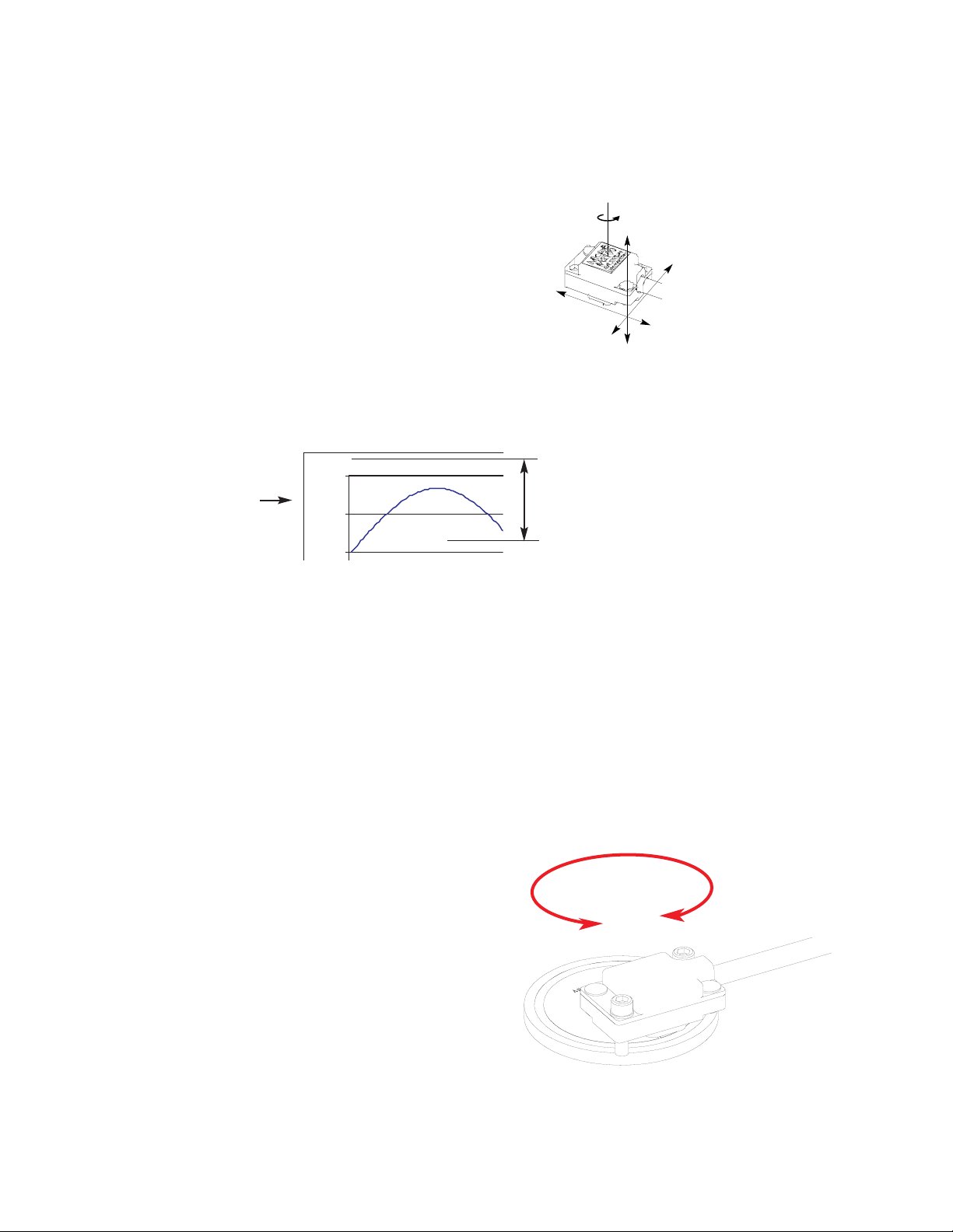
5
Page 11
4
INDEX TRACK ALIGNMENT
The M1500V must be aligned for both the main
and index tracks. When properly aligned, the
sensor will produce an index window as the
sensor passes over the index mark. The index
window is approximately one fringe wide
(20µm). To verify proper index track alignment,
use a digital oscilloscope triggered on the index
window. Refer to the interface drawing for the
index window pinout.
Confirm proper alignment of the main track over
the full range of motion. If not aligned over the
entire range of motion, loosen the sensor
mounting screws and repeat steps 4 and 5.
0
0.6
1.2
0.8 V
pp
x
Y
Z
θ
z
To align the sensor, move it
in the Y or θz directions.
MAIN TRACK ALIGNMENT
If benching dimensions cannot be provided, proper sensor
alignment may require minor adjustments to the sensor
position with respect to the scale. This can be performed by
maximizing the sine signal from the M1500V.
Installation Instructions
Rotary Encoders - Using Sin/Cos Signals - Alignment
`
1.7 V offset
(nominal)
Using an oscilloscope, monitor the sine or cosine signal (refer
to the interface drawing for pinouts) while moving the sensor
over the scale. Align the sensor until 0.8 volts peak-to-peak
+/- 25% is obtained. When alignment is completed, tighten
the sensor mounting screws (0.37Nm [3.3 inch-lbs.] maximum
torque).
Page 14
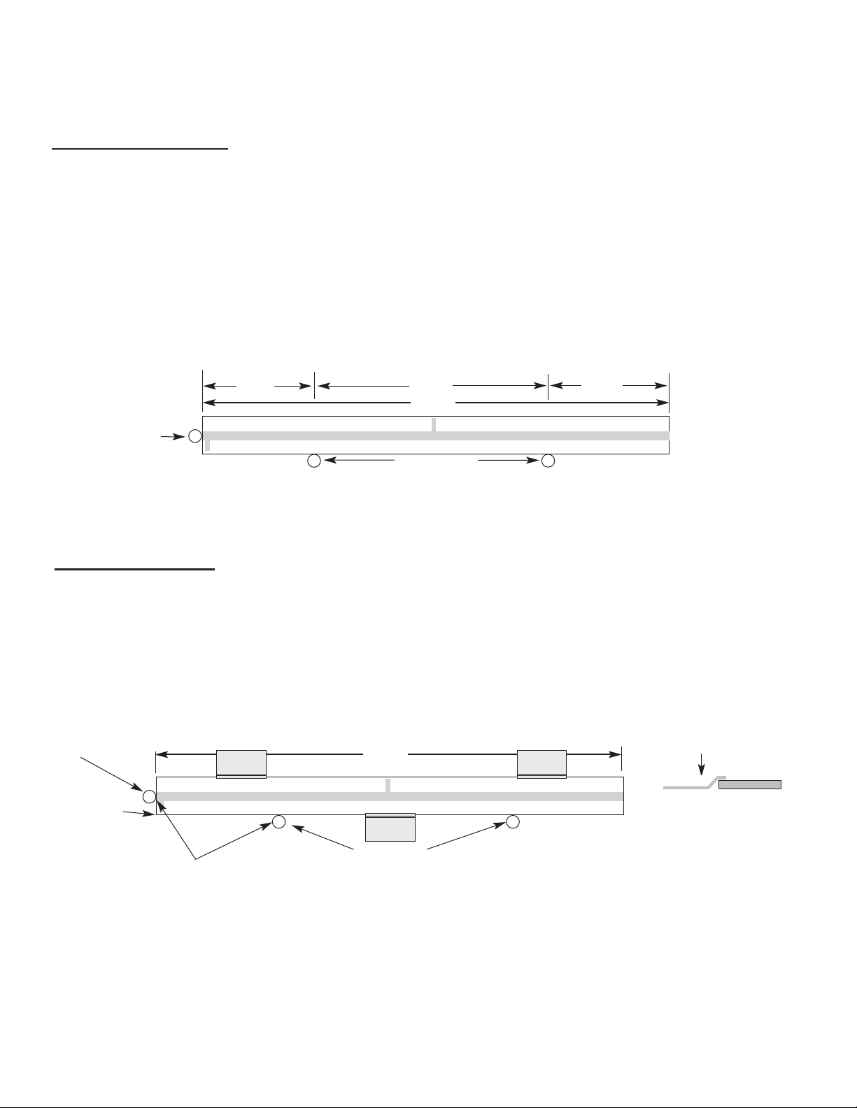
Reference Section
Installation of Linear Scales
MicroE Systems
L
0.2L
0.6L
0.2L
Benching pins
Positioning the Scale
Note: Before beginning mounting procedure, use talc-free gloves or finger cots to handle the scales. Also use vacuum compatible handling procedures and materials .
"Benching" the scale to the system means aligning the scale by means of benching pins. Pin locations are described on the appropriate interface drawing.
Two benching pins are recommended on the long side of the scale and one at the end as shown . This is marked datum A on the interface drawing.
Position the benching pins in from either end. 20% of the overall
scale length is the recommended location from the edge.
Be sure the benching pins do not extend too high in the Z direction to
prevent mechanical interference with the sensor or sensor mount.
2
1
End
Benching
Pin
Mounting the Scale
End Benching
Pin
Hard epoxy
at one corner,
this end only.
Suggested Epoxy and Clamp Mounting
1
Make sure the mounting surface is
clean and dry.
Scale clamps (customer supplied) may be used to mechanically secure the
scale. The clamps should allow for thermal expansion of the scale and
mounting surface. Make sure that the clamps do not interfere with the sensor
or sensor mount. Note: adhesive used on clamps supplied by MicroE is not
vacuum rated.
Side view showing
suggested scale
clamps and scale.
Space clamps every
75mm on scales over
150 mm in length.
4
Apply a hard, vacuum compatible epoxy to the
end of the scale at the end benching pin.
3
MicroE Systems
L
2
Align the scale by placing the edges
against the benching pins.
Benching pins
Scale clamp
Mounting clamp
Mounting clamp
Mounting clamp
Page 12
Page 15
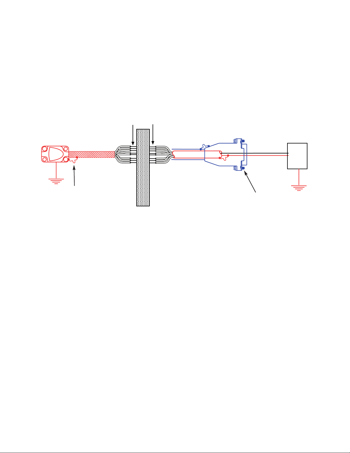
Page 13
Installation Reference Guide
Mercury encoders require a minimum of 4.75V DC continuously. When designing circuits and extension cables to use Mercury encoders, be sure
to account for voltage loss over distance and tolerances from the nominal supply voltage so that at least 4.75V DC is available to the Mercury
encoder under all operating conditions. The input voltage should not exceed 5.25V DC.
Grounding Instructions for Mercury 1500V Encoder Systems
Recommendations for Power
Electrically conductive mechanical connection (as supplied by
MicroE Systems).
Do not ground shroud.
Shielding Instructions
Customer-installed connectors at the vacuum chamber wall must electrically shield the signal wires from Electro Magnetic Interference,
Radio Frequency Interference and Electro Static Discharge. The connectors' shielding must completely surround the wires with no gaps,
including intimate electrical contact 360 degrees around the outer cable shields at the ends of the cables supplied with flying leads.
The inner shield of the cable that is attached to the SmartPrecision electronics module must be electrically isolated from the outer
shield.
Important Note
MicroE Systems recommends testing the motion subsystem after the Mercury 1500V encoders are installed using your vacuum throughwall connectors. The testing should prove that the motion system has sufficient immunity to Electro Magnetic Interference, Radio
Frequency Interference and Electro Static Discharge according to the application requirements.
Correct grounding can be implemented in several ways depending on how the customer implements the connections through the vacuum chamber wall. The diagram below is suitable where:
•The outer cable shields are electrically isolated from each other at the vacuum chamber wall.
•The sensor is mounted with good electrical contact to a well-grounded surface. (Note that an electrical path through
bearings will not result in a well-grounded sensor.)
Note: specific applications may require a different grounding scheme. Contact MicroE Systems for applications support.
Connector pins
Power
Supply
5 Volts
0 Volts
Vacuum Chamber wall
Note: Specific applications may require a different grounding scheme. Please contact MicroE Systems
Application grouip with details for assistance.
Page 16
Page 14
Mercury 1500V
Signal Twisted Pair
A+ Pair 1
AB+ Pair 2
BIndex+ Pair 3
Index-
+5V Pair 4
GND
Customer Interface Cable Requirements
Customer cables that interface to Mercury series encoders must have the following characteristics:
• Twisted pair signal wiring.
• Characteristic impedance of 100-120 ohms.
• Sufficient wire gauge to meet the minimum voltage requirement at the encoder, for example 24AWG gauge wire for a 2m length cable.
Examples of acceptable cables with 24 AWG gauge wire and 4 twisted pairs are Belden 9831, 8104, and 9844 or other
manufacturer's equivalents.
• Single shield cable with a minimum of 90% coverage. Note that a double shielded cable may be required in high-noise applications.
Signal Wiring:
Each differential signal should be connected to a corresponding twisted pair as follows:
Shield Termination:
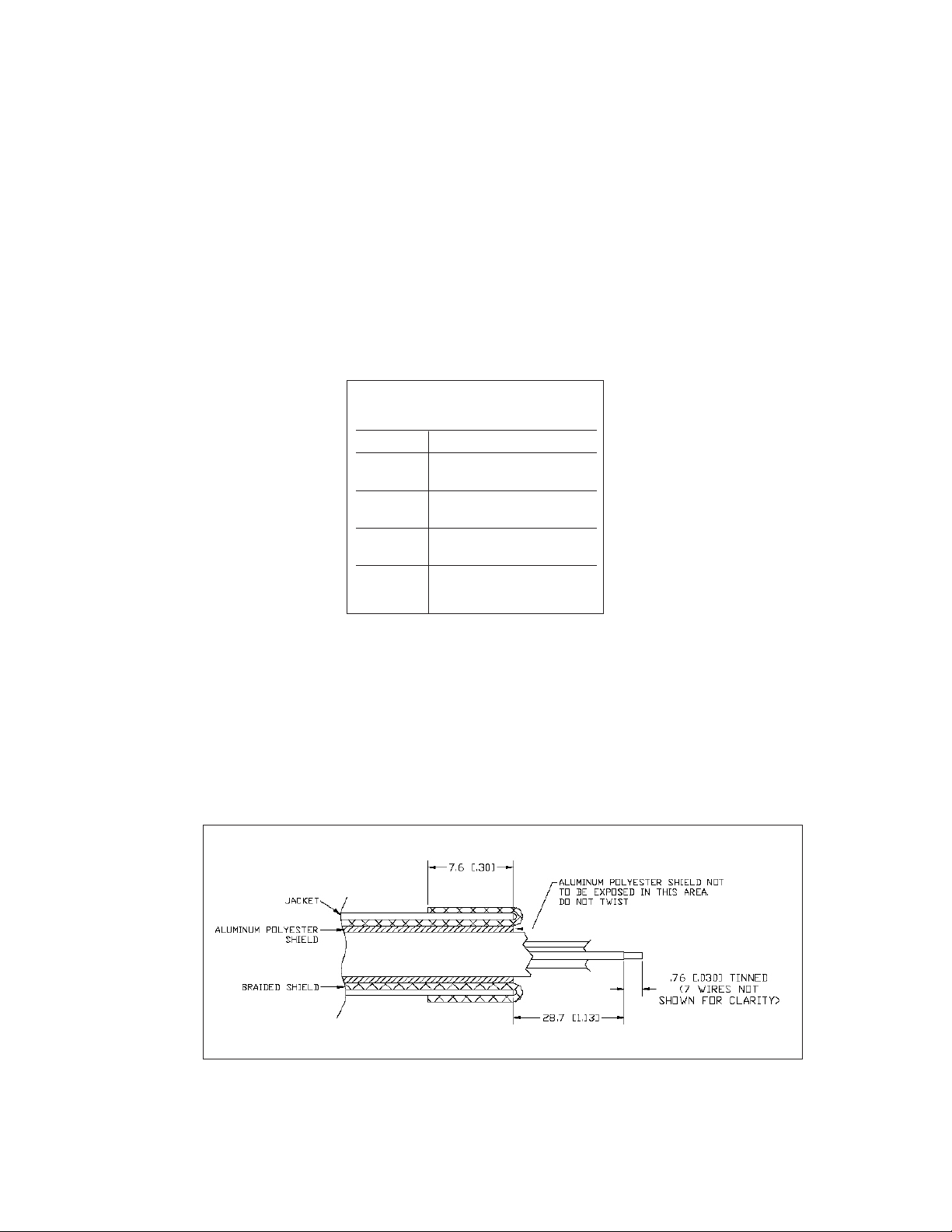
The customer's cable shield should be in 360° contact with the connector shroud and the connector shell to provide complete shielding. The
connector shell should be metal with conductive surfaces. Suggested metal connector shells for use with Mercury 3500, 3000, 3000Si,
and 2000 encoders: AMP 748676-1 or equivalent; for Mercury 1000 and 1500V encoders: AMP 745172-3, -2, or -1 where the dash number is
dependent on the customer's outside cable diameter. The shield should be terminated as illustrated in the following diagram.
Fold braided shield back over jacket. Example shows double-shielded cable. Dimensions shown
are for illustration only.
Page 17
Page 15
SINE+/COSINE+
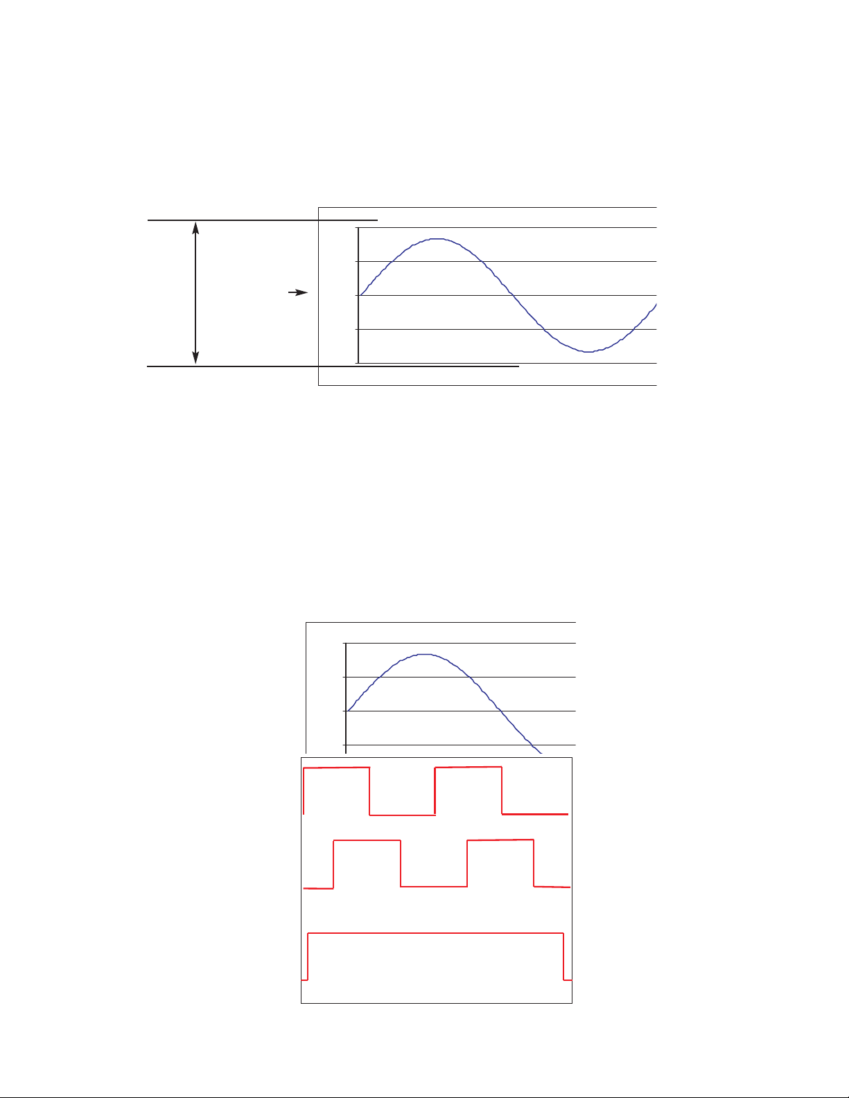
Analog signal with nominal peak to peak amplitude of 0.8V. The output signal has a source impedance of 1KΩ. This signal is only used to
align the sensor using an oscilloscope and is not suitable for feedback in a control system.
Output Signal Description
-1.2
-0.6
0
0.6
1.2
Output Signal Description
A+/A- Digital Quadrature output. Signal is a RS-422 compatible square wave.
Pulses are 90° out of phase with B+/B- outputs. Please see below.
B+/B- Digital Quadrature output. Signal is a RS-422 compatible square wave.
Pulses are 90° out of phase with A+/A- outputs. Please see below.
Index Window
The Index Window defines one particular fringe on the grating.
A+
B+
Index+
A+, B+ and Index Window+
0.8V pp ±25%
single ended
Output from 8X encoder shown
1.7 V offset
(nominal)
-0.6
0
0.6
1.2
Page 18
Troubleshooting
Problem
The Power/Calibration indicator will not come on.
Solution
• Make sure the M1500V 15-pin D connector is fully seated and connected.
• Confirm that +5 Volts DC is being applied to pin 12 on the M1500V 15-pin D connector and that pin 13 is connected to ground.
Problem
Can't get the SmartPrecision Alignment Tool "Signal" LEDs better than red or yellow; or the green, “ green” indicator doesn't
stay illuminated over the full length of the scale.
Solution
• Verify that the sensor has been aligned to the scale and that the mounting screws are tight. Check the dimensions for the mechanical
mounting holes (and clamps if any) to make sure that the sensor is correctly located over the scale. Refer to the appropriate interface drawing.
• Check that the scale is firmly mounted and can't jiggle or move in other than the intended direction.
• Make sure that the scale is clean over its entire length or circumference. Use the recommended Cleaning Scales procedure.
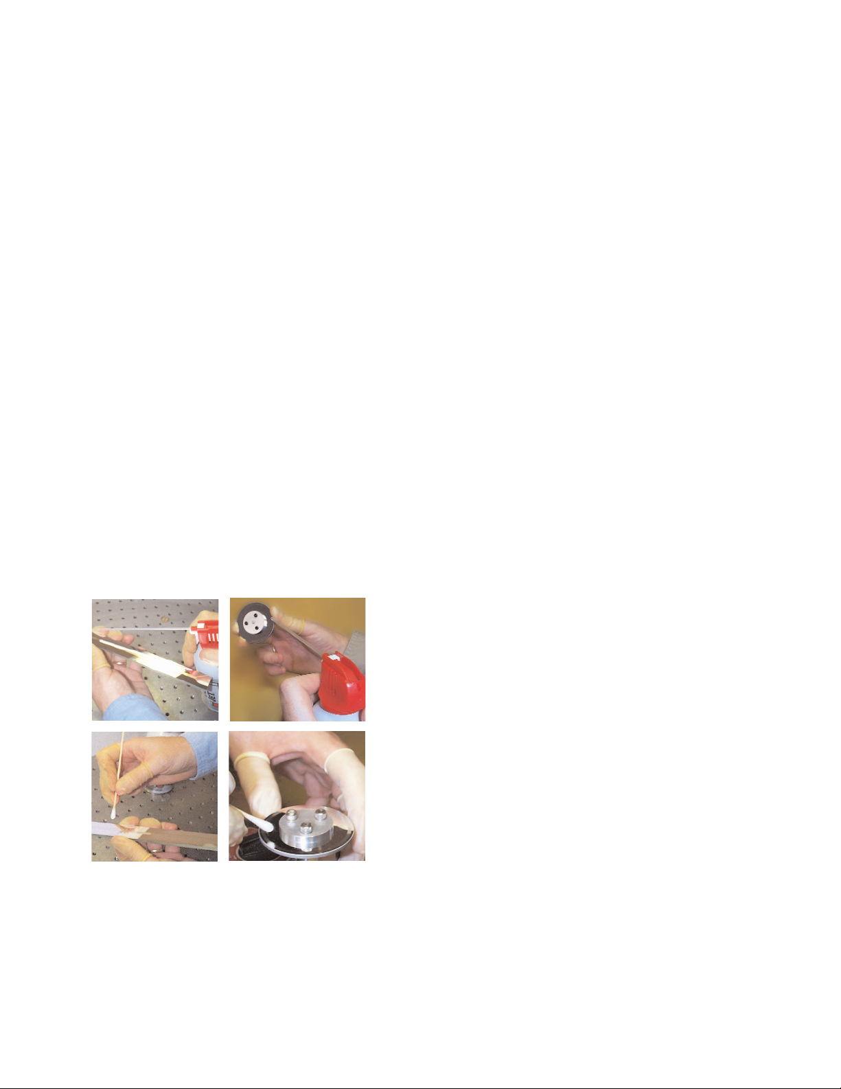
General Particle Removal
Blow off the contamination with nitrogen, clean air,
or a similar gas.
Page 16
Contamination Removal
Use a lint-free cleanroom wipe or
cotton swab dampened with isopropyl
alcohol or acetone only to wipe the
surface clean. Handle the scale by the
edges. Do not scrub the scale.
Cleaning Scales
Page 19

World Headquarters: 125 Middlesex Turnpike • Bedford • MA 01730 USA
www.microesys.com • [email protected] • T. [781] 266-5700 • F. [781] 266-5112
© 2008 MicroE Systems
Contact MicroE Systems
Thank you for purchasing a MicroE Systems product. You should expect
the highest level of quality and support from MicroE. If you want to
download the Mercury Encoder Installation Manual, Data Sheet or
Interface Drawing, browse www.microesys.com and click on the
Mercury Encoders button.
 Loading...