

Page 1
MTE
™
Series Encoders
Sensor Installation
Manual and Reference
Guide
MicroE Systems • 125 Middlesex Turnpike • Bedford, MA 01730 • USA
www.microesys.com info@microesys.com T. 781-266-5700
MTE-IM Series Rev C1 ©2015 MicroE Systems

Page 2
Table of Contents
MTE™Sensor Installation
Introduction
Introduction (Precautions, Patents, Manual Revisions) ...............................................................3
Recommendations for Power, Installation Consideration .........................................................4
Items Required for Sensor Installation .........................................................................................5
MTE, Top Mount Configuration
System Overview Diagram ...........................................................................................................6
Sensor Head Installation .............................................................................................................7
Sensor Head Aignment ................................................................................................................8
MTE, Side Mount Configuration
System Overview Diagram ............................................................................................................9
Sensor Head Installation ............................................................................................................10
Sensor Head Alignment ..............................................................................................................12
Appendix
A. Specifications ......................................................................................................................13
B. Wiring Diagrams ..................................................................................................................14
C. Interface Cable Requirements ......................................................................................15,16
D. RS-422 Compliance ............................................................................................................17
E. Troubleshooting ..................................................................................................................18
F. Order Guide ........................................................................................................................19
Contacting MicroE Systems
Contact MicroE............................................................................................................................20
Page 3
LASER SAFETY INFORMATION: MTE Series
This product is sold solely for use as a component (or replacement) in an electronic product; therefore it is not
required to, and does not comply with, 21 CFR 1040.10 and 1040.11 which pertain to complete laser products. The
manufacturer of the complete system-level electronic product is responsible for complying with 21 CFR 1040.10
and 1040.11 and for providing the user with all necessary safety warnings and information.
MicroE encoders contain an infrared laser diode or diodes. Emitted invisible laser radiation levels have been
measured to be within the CDRH Class 1 range, which is not considered hazardous; however, to minimize
exposure to the diverging beam, the encoder sensor should be installed in its operational configuration in close
proximity to the encoder scale before power is applied.
• Invisible laser radiation; wavelength: 850 nm
• Max power 2.4 mW CW
• CAUTION – The use of optical instruments with this product will increase eye hazard. DO NOT VIEW
DIRECTLY WITH OPTICAL INSTRUMENTS (MICROSCOPES, EYE LOUPES OR MAGNIFIERS).
• All maintenance procedures such as cleaning must be performed with the MicroE encoder turned off.
• Do not insert any reflective surface into the beam path when the encoder is powered.
• Do not attempt to service the MicroE encoder.
Precautions
Follow standard ESD precautions. Turn power off before connecting the sensor. Do
not touch the electrical pins without static protection such as a grounded wrist strap.
Do not touch the tape/glass scale unless you are wearing talc-free gloves or finger
cots. Please read this installation manual for full instructions.
1
2
MTE models are CE and RoHS compliant.
Manual Version Numbers
MTE-IM Sensor Installation Rev C, issued May 2014
Changes: Page 5, changed Items Required to Items Recommended. For Model ZG-CET,
changed ‘ships with each sensor’ to ‘sold separately.’
MTE-IM Sensor Installation Rev B, issued February 2014
Changes: Added Side Mount Configuration.
MTE-IM Sensor Installation Rev A, issued November 2013
Changes: N/A
Related Documents
-MTE Data Sheet
-MTE Interface Drawing
-Compact Encoder Tape (CET™) Scale Installation for MTE Series Encoders
INVISIBLE LASER RADIATION
DO NOT VIEW DIRECTLY WITH OPTICAL
INSTRUMENTS
(MICROSCOPES, EYE LOUPES OR
MAGNIFIERS)
RoHS

Page 4
Recommendations for Power; Installation Considerations
MTE™Series Encoders
1.
Recommendations for Power
MTE™encoders require a minimum of 4.75VDC continuously. When designing circuits and extension
cables, be sure to account for voltage loss over distance and tolerances from the nominal supply
voltage so that at least 4.75VDC is available to the MTE encoder under all operating conditions. The
input voltage should not exceed 5.25VDC.
2.
Installation Considerations
The MTE encoder is a precision electronic instrument. It has been designed to function in a wide
range of applications and environments. To take full advantage of the modular system design,
considerations should be made to allow easy access to the sensor for service and/or replacement.
For optimal performance and reliability:
DO follow standard ESD precautions while handling the sensor and interpolator.
DO allow proper alignment clearance for sensor head alignment.
DO follow setup instructions for the encoder system.
DO, where possible, install the scales in an
“upside down” or vertical position to minimize accumulation of dust.
DO consider redundant encoders or additional feedback devices as part of an overall risk
management program for medical applications.
DO NOT store sensors in an uncontrolled environment.
DO NOT electrically overstress the sensor (Power supply ripple/noise).
DO NOT intentionally “hot swap” the sensor if the device is energized.
DO NOT use in high contamination applications (dust, oil, excessive humidity, or other airborne
contaminants.).

Page 5
System Overview
MTE™Series Encoders
Items Recommended for MTE Encoder Installation Using Compact Encoder Tape (CET)
Scales
• Hex wrench (M2.5 for Top Mount, 5/64”, M3.5 and M2.5 for Side Mount).
• For MTE, Top Mount configuration
- Z height spacer Model Number: ZG-CET (sold separately).
• For MTE Side Mount
Side Mount Bracket Kit, Model Number: BK-SM-MTE.
- Z height spacer shim, ships with each bracket kit - 1.00mm (red) for use with CET scales.
• Optional: MK-FFA bracket kit for installation into industry-standard mounting hole patterns.
Refer to encoder model data sheets for detailed ordering guide and more information
about MicroE Part Numbers.
Page 6
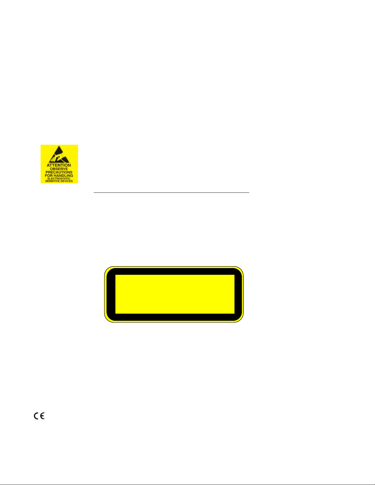
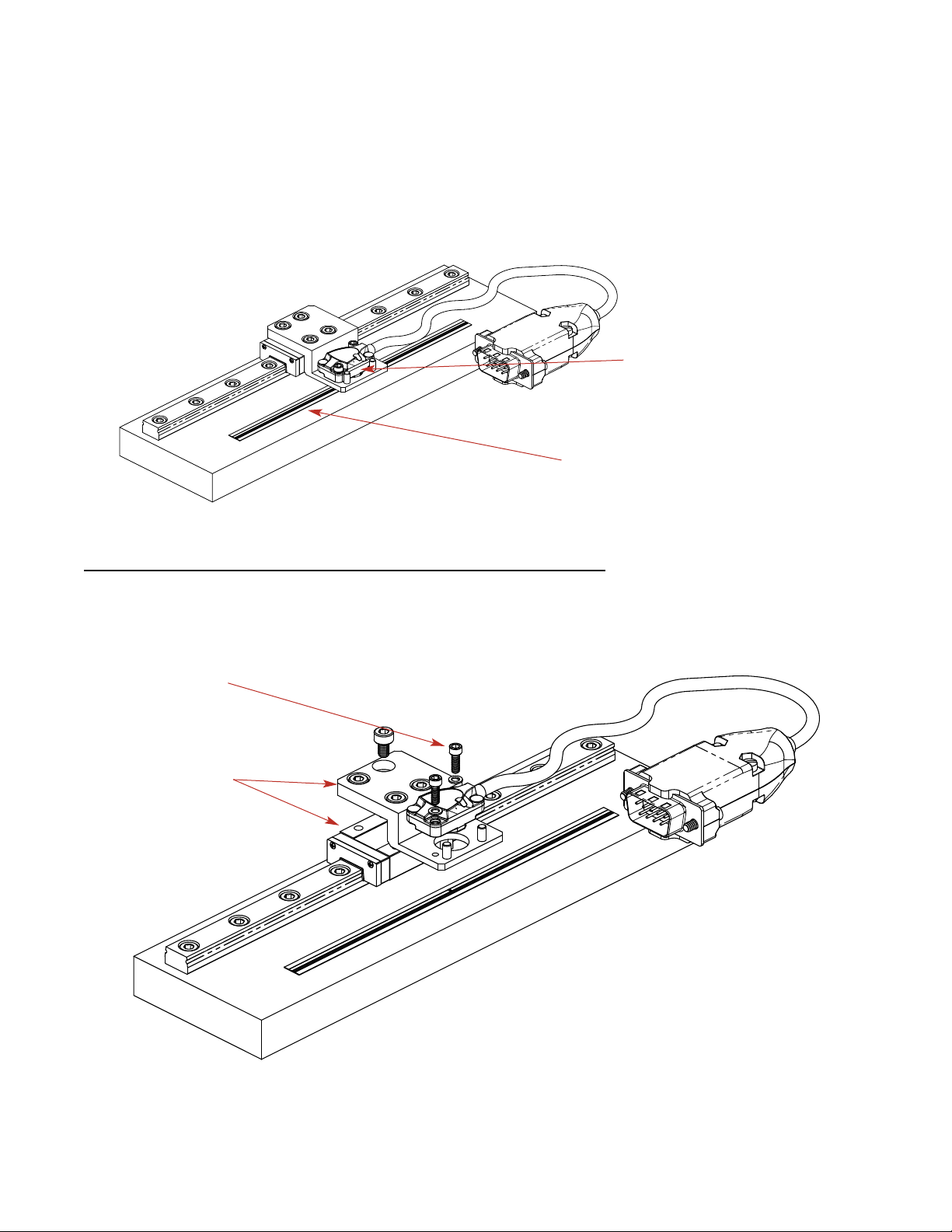
System Overview, (Top Mount Configuration)
MTE™Series Encoders
MTE
TM
Series
System View
Expanded View
Sensor
(shown attached on a linear slide base
with mounting bracket)
Typical user-supplied
sensor mounting bracket
Sensor mounting screws (2)
and flat washers (2)
Compact Encoder Tape scale
(shown mounted on a stationary
surface)

Page 7
Sensor Head Installation (Top Mount Configuration)
MTE™Series Encoders
1.
Verify Sensor Mounting Surface Height
Verify that the distance between the mounting
surface of the sensor and the top of the scale is as
follows:
Tape scale after blue protective film is removed:
3.84 mm ± 0.15 mm.
MicroE's Z-axis height gauge can be used to easily
verify this distance. (P/N: ZG-CET)
Use the gauge to check that there are no
gaps between:
1. The mounting surface of the gauge and the
mounting bracket, or
2. The bottom surface of the gauge and the scale.
Place the gauge in position and use the mounting
screws as guides. If the bottom of the gauge hits the
tape, you will see the gap between the gauge
bottom mounting surface and your mounting bracket
surface.
If you hand tighten the sensor mounting screws,
there should be no gap between the tape scale and
the bottom of the plastic gauge tool.
2.
Install Sensor
Install the sensor on the mounting surface
referencing the appropriate datum surface as
shown on the Interface Drawing. Use two M2 or
2-56 screws to loosely affix the sensor.
A benching edge is recommended to locate the
sensor to meet the mechanical mounting
tolerances. Refer to the Interface Drawing for
recommended location and height of edge.
Note: Tolerance for each axis is specified
independently, assuming nominal alignment in all
other axes.
Gauge P/N: ZG-CET
MTE
Sensor Alignment Tolerances
Axis Alignment Tolerance
X Direction of Motion
Y ± 0.15mm
Z ± 0.15mm
θ
X
± 1.0°
θ
Y
± 2.0°
θ
Z
± 2.0°

Page 8
Sensor Head Alignment (Top Mount Configuration)
MTE™Series Encoders
1.
Proper sensor alignment may require minor
adjustments to the sensor position with respect to
the scale. This can be performed easily using the
sensor’s LED indicator.
The red, yellow, or green Signal LEDs will light
depending on sensor alignment. Slowly move the
sensor by allowing it to slide on the mounting
surface until the green Signal LED, is illuminated.
Optimal alignment will be displayed as a “bright
green” Signal LED.
Confirm that the green Signal LED blinks when
passing over the index. If not, readjust the sensor
in the Y direction and repeat the above procedure.
When alignment is completed, tighten the sensor
mounting screws (0.37Nm [3.3 inch-lbs.] maximum
torque).
2.
Confirm that the Signal LED remains green over
the full range of motion by sliding the scale past
the sensor. The green Signal LED must remain on
over the entire range. If not aligned over the entire
range of motion, loosen the sensor mounting
screws and repeat steps 1 and 2.
The LED will, and should, blink when passing
the index mark.
Z
Y
X
θ
z
Green:
Optimal
Performance
Yellow:
Marginal
Performance
Red:
Improper
Performance

Page 9
System Overview, (Side Mount Configuration)
MTE™Series Encoders
MTE
TM
Series
System View
Expanded View
MTE Sensor
Typical user-supplied
sensor mounting fixture
Sensor mounting screws
(2) and flat washers (2)
Compact Encoder Tape scale
(shown mounted on a stationary
surface)
Typical user-supplied
sensor mounting fixture
MTE Side Mount Bracket Kit,
Model Number: BK-SM-MTE
D
“D” tape scale datum edge
(see MTE Interface Drawing)
Index track

Page 10
MTE
Sensor Alignment Tolerances
Axis Alignment Tolerance
X Direction of Motion
Y ± 0.15mm
Z ± 0.15mm
θ
X
± 1.0°
θ
Y
± 2.0°
θ
Z
± 2.0°
Z
Y
X
θ
z
Sensor Head Installation (Side Mount Configuration)
MTE™Series Encoders
Sensor Mounting Orientation and
Tolerances
Axis diagram (Side mount bracket not shown.)
1.
Install the Sensor
Use a wrench and M2, M3 screws to install the sensor and Side Mount Bracket Kit. Refer to the interface
drawing to make sure sensor is oriented properly with reference to the scale.
1.2 Install the sensor into the
Side Mount Bracket Kit.
Customer mounting
fixture
1.1 Install the Side Mount
Bracket Kit on to the customer
mounting fixture.
Customer mounting
fixture
Side Mount Bracket Kit,
Model Number: BK-SM-MTE
Side Mount Bracket Kit

Page 11
Sensor Head Installation (Side Mount Configuration)
MTE™Series Encoders
2.1 Loosen the Mounting
Fixture in the Y-axis.
2.3 Press down gently in
the Z-axis and tighten
the mounting fixture
screws.
2.2 Place shim between the bottom of the
Bracket Kit Adaptor and the top of the scale.
Mounting
fixture loose in
the Y-axis.
2.4 Carefully remove the shim by rotating it
off the scale with the shim’s handle.
Gently push
the mounting
fixture/Bracket
Kit and sensor
against the top
of the tape
scale in the
z-axis.
Z-Height (red)
spacer
Mounting fixture
screws
2.
Verify Sensor Mounting Surface Height
Refer to the MTE interface drawing for detailed dimensions.
Use the Z-Height red spacer shim (1.00mm) to set the proper Z-height distance between the bottom
surface of the Side Mount Bracket Kit/MTE Sensor and the top of the scale.

Page 12
Sensor Head Alignment (Side Mount Configuration)
MTE™Series Encoders
1.
Proper sensor alignment may require minor
adjustments to the sensor position with respect to the
scale. This can be performed easily using the sensor’s
LED indicator.
The red, yellow, or green Signal LEDs will light
depending on sensor alignment. Optimal alignment will
be displayed as a “bright green” Signal LED.
Confirm that the green Signal LED blinks when
passing over the index. If not, readjust the sensor in
the Y-direction and repeat the above procedure.
When alignment is completed, tighten the sensor
mounting screws (0.37Nm [3.3 inch-lbs.] maximum
torque).
2.
Confirm that the Signal LED remains green over the full range of motion by sliding the scale past the
sensor. The green Signal LED must remain on over the entire range. If not aligned over the entire
range of motion, loosen the sensor mounting screws and repeat step 1.
The LED should blink when passing the index mark.
Z
Y
X
θ
z
Green:
Optimal
Performance
Yellow:
Marginal
Performance
Red:
Improper
Performance
Loosen the
sensor mounting
screws/washers
to reposition the
sensor in the
Y-axis if needed.

Page 13
Appendix A
Specifications
Agency Standards Conformance: In accordance with
Electromagnetic Compatibility Directive 2004/108/EC:
EN 55011:2007
EN 61000-4-2, -3, -4, -6
Shock 300G 0.5 ms half sine
Vibration 30G at 17Hz
Sensor Cable Double Shield
Diameter 3.6mm (0.142")
Flex Life 20x10
6
cycles @ 20mm bending radius
Standard 9 pin D-sub connector
Outputs
Digital A-quad-B, Index Window; A, B and IW outputs are
differential. Alarm is single ended open drain.
Signal Level
A/B/I (differential): RS-422 compatible
A/B/I (single ended): High>4.2VDC, Low <0.2VDC
Alarm: 0.2VDC-Vcc
Operating and Electrical Specifications
Power Supply 5VDC +
5% @ 135mA max. when used
with recommended termination, 80mA
max. unterminated
Temperature
Operating 0 to 70
o
C
Storage -20 to 85oC
Humidity 10 to 90% RH non-condensing
Linearity
Compact Encoder Tape Scale Linearity ≤ +10µ
m/m*
*After two point correction in the customer’s controller.
Sensor Size & Weight
Height Width Length
0.33 [8.4mm] 0.50 [12.7mm] 0.81 [20.6mm]
Weight 5g (without cable)
Reliability Information
5 Year Expected Reliability >99.8% under normal operating
conditions
Digital Output Signals
System
MTE sensors are compatible with PurePrecision
TM
Compact
Encoder Tape (CET
TM
) Scale.
Scale Pitch 20µm
System Resolution 5
µ
m, 2.5µm, or 1µm
(specify at time of ordering)
A
B
Quadrature
Open drain, requires external pull-up.
Pins 8 & 4
Pins 7 & 3
Pins 6 & 2
20µm Typical
4.5VDC
Pin 1
Duration of alarm event
Vcc
Alarm
Index
Inverse signals are not shown for clarity.

Page 14
Appendix B
Wiring Diagrams
Connector Pin Configuration
Electrically conductive mechanical
connection (as supplied by MicroE
Systems).
INNER SHIELD:
Insulated from outer shield, sensor case, and
connector housing. Connected to circuit common
internally as supplied by MicroE Systems
OUTER SHIELD: Connected to
sensor and connector housing
Grounding Considerations
Sensor mounted with good electrical contact to well grounded surface (preferred):
Sensor mounted to poorly grounded or non-conducting surface:
NOTE: GND and INNER SHIELD ARE INTERNALLY CONNECTED.
Max cable length: 5m. Contact MicroE Applications Engineering if longer length required.
Recommended Signal Termination
Cable Zo=
120 Ω
MTE Series
Encoder
Customer
Electronics
120
Ω
+
−
Digital Outputs:
A, B, I
A, B, I
Standard RS-422 Line Receiver Circuitry
5 Volts
0 Volts
POWER
SUPPLY
5 Volts
0 Volts
POWER
SUPPLY
Alarm output is an open drain,
N-channel MOSFET. Drain circuit is normally closed (current
flows) and opens when the
encoder signal is too low. Alarm
requires the use of an external
pull-up resistor. See customer
supplied circuit example on right.
Alarm circuit
Alarm:
PIN 5
PIN 1
PIN 9
PIN 6
$#"!
#
#
"
Power
Supply
5 Volts
0 Volts
Power
Supply
5 Volts
0 Volts

Page 15
Appendix C
Interface Cable Requirements
1. Customer Interface Cable Requirements
Customer cables that interface to MTE™series encoders must have the following characteristics:
• Twisted pair signal wiring.
• Characteristic impedance of 100-120 ohms.
• Sufficient wire gauge to meet the minimum voltage requirement at the encoder, for example 24AWG
gauge wire for a 2m length cable. Examples of acceptable cables with 24AWG gauge wire and 4
twisted pairs are Belden 9831, 8104, and 9844 or other manufacturer’s equivalents.
• Single shield cable with a minimum of 90% coverage. Note that a double shielded cable may be
required in high-noise applications.
MTE
Signal Twisted Pair
A+ Pair 1
A-
B+ Pair 2
B-
Index+ Pair 3
Index-
+5V Pair 4
GND
Fold braided shield back over jacket. Example shows double-shielded cable.
Dimensions shown are for illustration only.
Jacket
Aluminum
Polyester
Shied
Braided
Shield
3. Shield Termination:
The customer's cable shield should be in 360° contact with the connector shroud and the connector shell to
provide complete shielding. The connector shell should be metal with conductive surfaces. Suggested metal
connector shells for use with MTE™ encoders: AMP 748676-1 or equivalent. The shield should be terminated
as illustrated in the following diagram.
2. Signal Wiring
Each differential signal should be connected to a corresponding twisted pair as follows:

Page 16
Appendix C
Interface Cable Requirements
4. Grounding:
The diagrams below show how to make the connections when the encoder's connector is plugged into the
customer's controller chassis. If a customer-supplied extension cable is used, it should be a double shielded
cable with conductive connector shells and must provide complete shielding over the conductors contained within
it over its entire length. Furthermore, the shields should be grounded at the connection to the controller chassis
the same way as the encoder connectors in the diagrams below.
5 Volts
0 Volts
Electrically conductive
mechanical connection
(as supplied by MicroE Systems).
POWER
SUPPLY
INNER SHIELD:
Insulated from outer shield, sensor case, and
connector housing. Connected to circuit common
inter
nally as supplied by MicroE Systems
OUTER SHIELD: Connected to
sensor and connector housings
4.1 Sensor mounted with good electrical contact to a well-grounded surface (preferred)
9 - pin D-sub connector grounding: The encoder's connector shell must be in contact with the customer-supplied
mating connector, which must be isolated from the controller's ground. If a customer-supplied shielded cable
connects the encoder to the controller, then the outer shield on the customer-supplied cable must be isolated
from the controller's ground.
The sensor mounting surface must have a low impedance (DC/AC) connection to ground. The encoder sensor
mounting surface may have to be masked during painting or anodizing to insure good electrical contact with the
sensor.
NOTE:
For best performance, isolate the encoder outer shield from motor cable shields and separate the encoder cable
as far possible from motor cables.
4.2 Sensor mounted to a surface that is grounded through bearings or a poorly-grounded surface, or
mounted to a non-conducting surface
9 - pin D-sub connector grounding: The encoder's connector shell must be in contact with the customer-supplied
mating connector, which must be connected to the controller's ground. If a customer-supplied shielded cable
connects the encoder to the controller, then the outer shield on the customer-supplied cable must be connected
to the controller's ground. The controller must be grounded to earth at the point of installation.
The encoder sensor must be mounted so that it is electrically isolated from ground.
5 Volts
0 Volts
POWER
SUPPLY
Power
Supply
5 Volts
0 Volts
Power
Supply
5 Volts
0 Volts

Page 17
The MTE is RS-422 compatible. Encoder signals are “sending end terminated.” Therefore customer
receiving terminations are not required. If you elect to use them, the supply current will increase.
Optional RS-422 compliant circuitry for long cable runs in harsh electrical environments is illustrated below.
Appendix D
RS-422 Compliance

Page 18
Appendix E
Troubleshooting
Problem
The Sensor LED indicator won’t turn on.
Solution
• Make sure that the MTE Series electronics’ 9-pin D-sub connector is fully seated and connected.
• Confirm that +5 Volts DC is being applied to the MTE Sensor. Refer to the MTE interface drawing for
proper pinouts.
Problem
Can't get the MTE Series electronics’ "Signal" LED better than red or yellow; or the green, “ Proper
Alignment” indicator doesn't stay illuminated over the full length of the scale.
Solution
• Verify that the sensor is mounted in the correct orientation with reference to the scale and scale
mounting reference edge. Refer to the Interface Drawing.
• Verify that the sensor has been aligned to the scale and that the mounting screws are tight. Check the
dimensions for the mechanical mounting holes (and clamps if any) to make sure that the sensor is
correctly located over the scale in the Y and Z dimensions. Refer to the Interface Drawing.
• Check that the scale is firmly mounted and can't jiggle or move in any direction.
• Make sure that the scale is clean over its entire length or circumference.

Page 19
Appendix F
Order Guide
How to Order
MK-FFA
FlexFit Adaptor Mounting Kit.
Reference design is available upon
request.
End Cap Kit, PurePrecision Tape Scales
EC Optional Tape Scale End Caps
Scales
Sensor Installation Tools
ZG-CET Z-Height Gauge, Compact Encoder
Tape, top mount configuration
FlexFit™ Adaptor
TSAT-CET
Tape Applicator Tool for MTE, top
mount configuration
CET™ Tape Scale Applicator Tools
(use for lengths >1m)
TSAT-SM-PPT
Tape Applicator Tool for MTE,
side mount configuration
CET20 – N – A – I
– xxxx –C
I = Individual Lengths
C = Continuous reel with index and
cut marks (unless otherwise
specified)
Length in mm (10mm-30,000mm)
For length >5000mm, contact
MicroE for custom P/N.
Sensor
MTE – 20 –2
Cable Length*
1 = 1.0m
2 = 2.0m
5 = 5.0m
Interpolation (Resolution)
4 = x4 (5
µ
m)
8 = x8 (2.5
µ
m)
20 = x20 (1
µ
m)
Index
I = Center Index
C = Custom Index
Example 1: CET20-N-A-I-4550-C
= 4550mm long, single center index (2775mm from
cut marks), continuous
Example 2: CET20-N-A-C-5xxx-I
= Multiple indexes, individually cut, with index
dimensions per factory issued part # 5xxx (e.g.,
index at 50mm and 350mm, segment length
400mm)
Example 3: CET20-N-A-C-5xxx-C
= Single index which is offset from center of segment,
continuous, with index dimensions per factory
issued part # 5xxx (e.g., index at 50mm from left cut
mark, segment length 400mm)
Compact Encoder Tape (CETTM)
* Custom cable lengths and connectors are available.
Contact MicroE Applications Engineering.
BK-SM-MTE
Side Mount Bracket Kit. Reference
design is available upon request.
MTE Side Mount Bracket Kit

Page 20
Contacting MicroE
MicroE Systems is a world leader in optical encoder technology with
offices in major industrial centers around the globe.
To learn more about MicroE Systems products, visit:
www.microesystems.com.
Our products have been used by thousands of companies worldwide to
solve a wide range of motion control applications. Our advanced
encoder technology and application expertise has driven innovations in
the design of machinery, equipment and instrumentation in many
industries, including medical, industrial, robotics, automation, metrology,
semiconductor manufacturing, packaging equipment, entertainment,
energy, military, and scientific research.
MicroE Systems
125 Middlesex Turnpike
Bedford, MA 01730 USA
T 781-266-5700
F 781-266-5112
info@microesys.com
www.microesystems.com
© 2015 MicroE Systems
 Loading...