

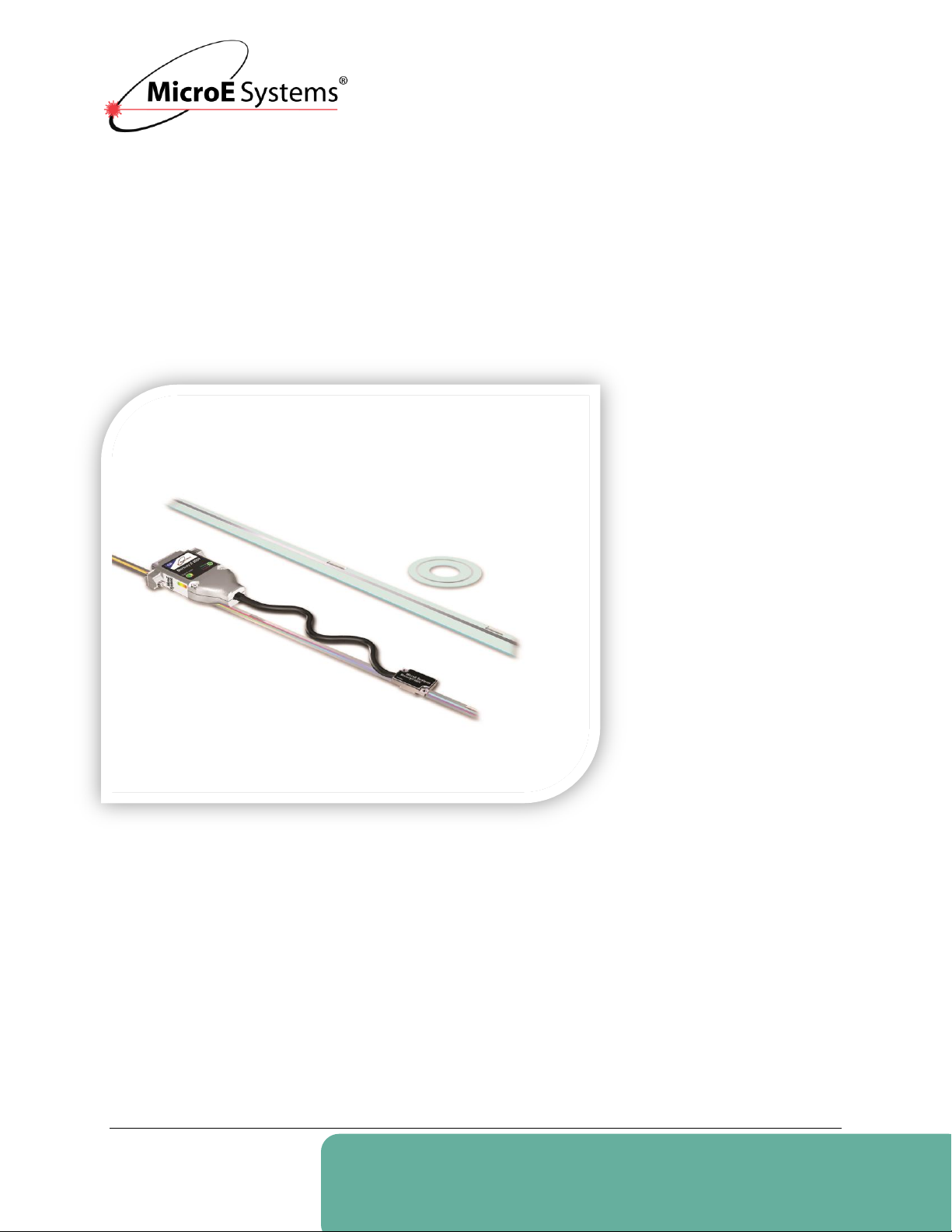
Mercury II™ 6000
Series Encoders
MicroE Systems • 125 Middlesex Turnpike • Bedford, MA 01730 • USA
www.microesystems.com
info@microesystems.com
T. 781-266-5700
F. 781-266-5112
Installation Manual
and Reference Guide
IM-Mercury-II-6000-Series Rev. 1
©2014 MicroE Systems

Introduction
Mercury II 6000 Series Encoders
Installation Manual and Reference Guide
Table of Contents
1.0 Introduction ...................................................................................................................................... 2
1.1 Overview ............................................................................................................................. 2
1.2 Precautions ......................................................................................................................... 2
1.3 Laser Safety Information ..................................................................................................... 2
1.4 Patents ................................................................................................................................ 3
1.5 Standards Compliance ........................................................................................................ 3
1.6 Related Documentation ...................................................................................................... 3
1.7 Manual Revisions ................................................................................................................ 3
1.8 Trademarks ......................................................................................................................... 3
2.0 Before Installation ............................................................................................................................ 4
2.1 Power Recommendations ................................................................................................... 4
2.2 Installation Considerations .................................................................................................. 4
2.3 Items Required for Installation ............................................................................................ 4
3.0 System Overview ............................................................................................................................. 5
3.1 System View ....................................................................................................................... 5
3.2 Expanded View ................................................................................................................... 5
3.3 SmartPrecision Alignment Tool ........................................................................................... 6
4.0 Sensor Installation ............................................................................................................................ 7
4.1 Sensor Mounting Orientation and Tolerances .................................................................... 7
4.2 Verify Sensor Mounting Surface Height .............................................................................. 7
4.3 Install Sensor ...................................................................................................................... 7
5.0 Sensor Alignment and Calibration ................................................................................................... 8
5.1 Using the Cal. Pushbutton .................................................................................................. 9
5.1.1 Sensor Alignment ................................................................................................... 9
5.1.2 Sensor Calibration ............................................................................................... 11
5.2 Using the Software ............................................................................................................ 14
5.2.1 Connect the Alignment Tool and Encoder ........................................................... 14
5.2.2 Use the FindMII Program to locate the Encoder .................................................. 15
5.2.3 Sensor Alignment and Calibration ....................................................................... 16
6.0 Alignment Verification with Connector LEDs ................................................................................. 19
7.0 Appendix ........................................................................................................................................ 20
7.1 Specifications .................................................................................................................... 20
7.2 Resolution and Maximum Speed Tables .......................................................................... 22
7.3 Wiring Diagrams ................................................................................................................ 25
7.4 Customer Interface............................................................................................................ 27
7.5 Serial Interface Specifications ........................................................................................... 30
7.6 Index Speed Considerations ............................................................................................. 35
7.7 RS-422 Compliance .......................................................................................................... 36
7.8 Troubleshooting ................................................................................................................ 37
8.0 Order Guide ................................................................................................................................... 38
9.0 Contacting MicroE .......................................................................................................................... 42
IM-Mercury_II_6000 Series Rev. 1 Page 1 ©2014 MicroE Systems
Introduction
Mercury II 6000 Series Encoders
Installation Manual and Reference Guide
MII6500
MII6700
MII6800
MII6800Si
MII6800Pa
1.0 Introduction
1.1 Overview
The instructions in this manual apply to the following Mercury II 6000 Series Encoders:
Refer to the Mercury II 6000 Series Encoder data sheet for additional details on ordering parts.
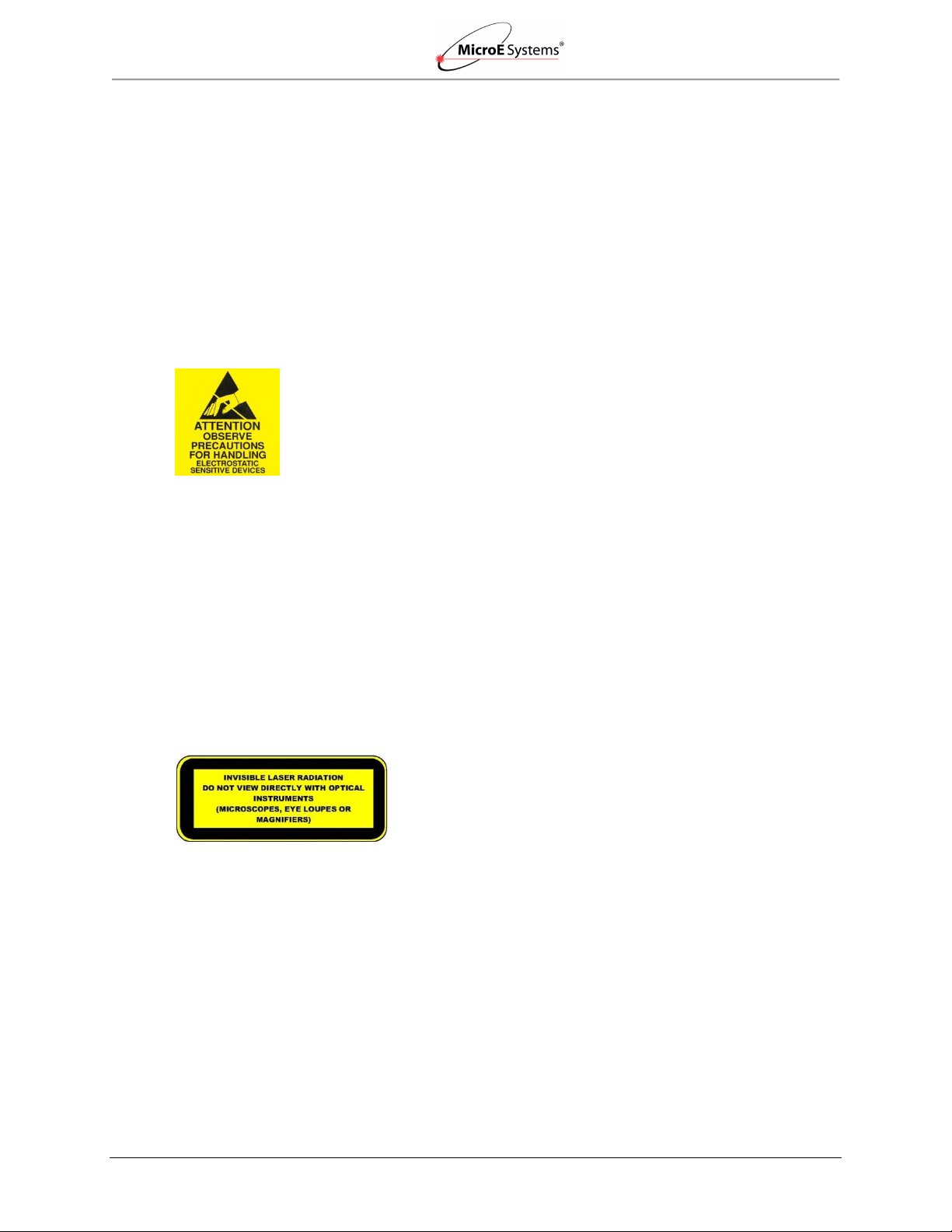
1.2 Precautions
1. Follow standard ESD precautions. Turn power to off before connecting
the sensor.
2. Do not touch electrical pins without static protection such as a
grounded wrist strap.
1.3 Laser Safety Information
This product is sold solely for use as a component (or replacement) in an electronic product;
therefore, it is not required to, and does not comply with U.S. FDA 21 CFR 1040.10 and 1040.11
which pertain to complete laser products. The manufacturer of the complete system-level
electronic product is responsible for complying with 21 CFR.
MicroE Systems encoders contain an infrared laser diode or diodes. Emitted invisible laser
radiation levels have been measured to be within the CDRH Class 1 range, which is not
considered hazardous; however, to minimize exposure to the diverging beam, install the encoder
sensor in its operational configuration in close proximity to the encoder scale before
applying power.
Invisible laser radiation; wavelength: 850 nm.
Maximum power of 4.8 mW CW for Mercury II.
Caution: The use of optical instruments with this product will increase eye hazard. Do
not view directly with optical instruments (microscopes, eye loupes, or magnifiers).
All maintenance procedures such as cleaning must be performed with the MicroE
Do not insert any reflective surface into the beam path when the encoder is powered.
Do not attempt to service the MicroE encoder.
IM-Mercury_II_6000 Series Rev. 1 Page 2 ©2014 MicroE Systems
encoder turned off.
Introduction
Mercury II 6000 Series Encoders
Installation Manual and Reference Guide
US 5,991,249
EP 895,239
JP 3,025,237
US 6,897,435
EP 1,451,933.
Version
Date
Notes
IM-M II 6000 Series Rev. A
11/21/2014
Initial Release. Combines coverage for entire series of
Mercury II 6000 Encoders.
1.4 Patents
Mercury II 6000 Encoders design covered by the following patents:
Additional patents and patents pending may apply.
1.5 Standards Compliance
Mercury II models are CE and RoHS compliant.
1.6 Related Documentation
Mercury II 6000 Series Encoders Data Sheet
Mercury II 6000 Series Encoders Interface Drawings
Mercury II PurePrecision Tape and Glass Scale Installation Manual and Reference
Guide
1.7 Manual Revisions
1.8 Trademarks
Mercury II™, PurePrecision™, and SmartPrecision™ are trademarks of MicroE Systems®.
IM-Mercury_II_6000 Series Rev. 1 Page 3 ©2014 MicroE Systems

Before Installation
Mercury II 6000 Series Encoders
Installation Manual and Reference Guide
Items Required for Installation
Item
Tape Scale
Glass Scale
Index and Limit Marker sheets
Hex Wrench for Sensor Mounting Screws
Finger Cots or talc-free gloves
Acetone or isopropyl alcohol
Lint-free cotton cloths or wipes
Two-part epoxy (Tra-Bond 2116 or equivalent)
Stick and disposable surface for stirring epoxy
Shears
Tape Applicator Tool*
Silicone adhesive
2.0 Before Installation
Review the items in this section prior to installing the encoder.
2.1 Power Recommendations
Mercury II encoders require a minimum of 4.75VDC continuously.
When designing circuits and extension cables to use Mercury II encoders, be sure to
account for voltage loss over distance and tolerances from the nominal supply voltage so
that at least 4.75VDC is available to the Mercury II encoder under all operating
conditions.
The input voltage should not exceed 5.25VDC.
2.2 Installation Considerations
The Mercury II encoder is a precision electronic instrument. It has been designed to function in a
wide range of applications and environments. To take full advantage of the Mercury II modular
system design, considerations should be made to allow easy access to the sensor (and
interpolator modules where applicable) for service and/or replacement. For optimal performance
and reliability:
DO follow standard ESD precautions while handling the sensor and interpolator.
DO allow proper clearance for sensor head alignment.
DO follow setup and calibration instructions for the encoder system.
DO, where possible, install the scales in an inverted or vertical position to minimize
accumulation of dust.
DO NOT store sensors in an uncontrolled environment.
DO NOT electrically overstress the sensor (power supply ripple/noise).
DO NOT intentionally “hot swap” the sensor if the device is energized.
DO NOT use in high contamination applications (dust, oil, excessive humidity, or other
airborne contaminants).
2.3 Items Required for Installation
In addition to the items identified in Section 3.0 System Overview, you will need the following
items available for installation:
Note*: Not required for some installations.
IM-Mercury_II_6000 Series Rev. 1 Page 4 ©2014 MicroE Systems

System Overview
Mercury II 6000 Series Encoders
Installation Manual and Reference Guide
Index Marker
15-Pin Male
D-Sub Connector
Double-Shielded
Cable
Left Limit Marker
Scale Mounting Surface Reference Edge (Benching Surface)
Tape Scale: shown mounted on
a fixed (non-moving) substrate.
Sensor: shown mounted on a
linear bearing using a
mounting bracket.
Alignment Tool
Sensor Connector
Mounting Screws
Typical User-Supplied
Sensor Mounting Bracket
Sensor Mounting Holes
Sensor Benching Pins
Bracket Mounting Holes
Right Limit Marker
Alignment Tool Adapter
3.0 System Overview
This section identifies parts for the sensor installation.
3.1 System View
3.2 Expanded View
IM-Mercury_II_6000 Series Rev. 1 Page 5 ©2014 MicroE Systems
System Overview
Mercury II 6000 Series Encoders
Installation Manual and Reference Guide
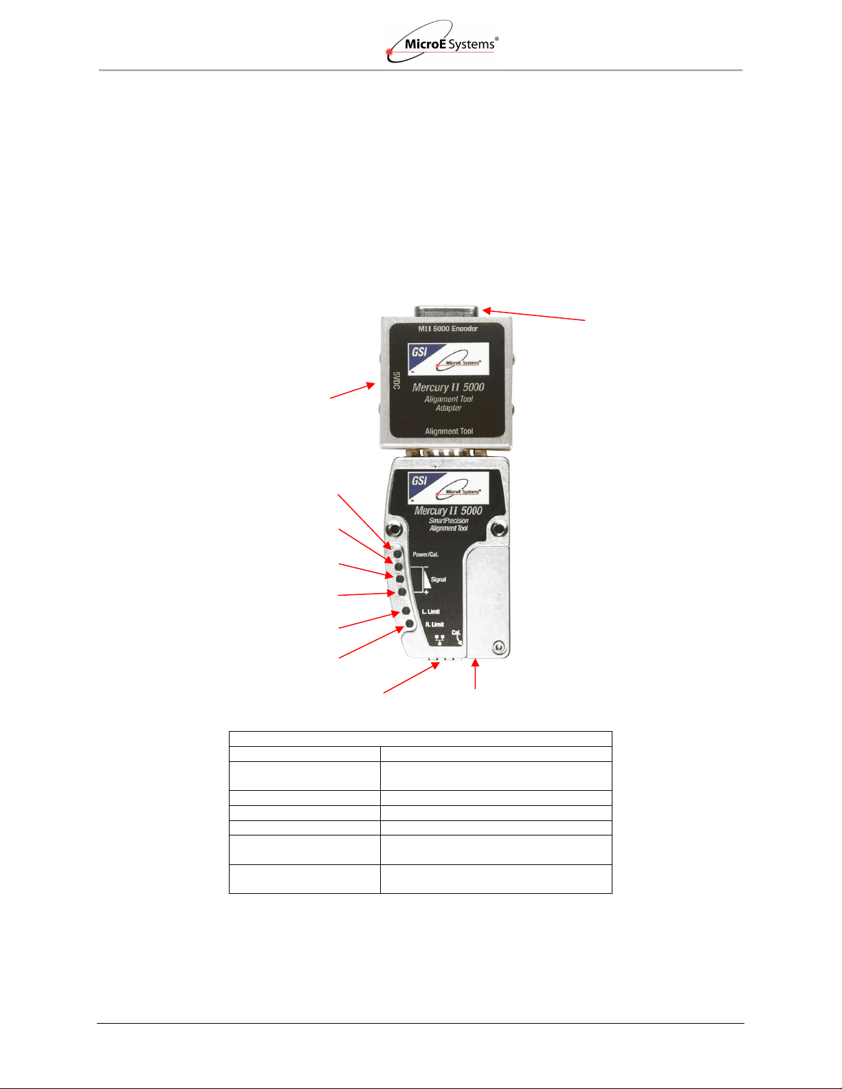
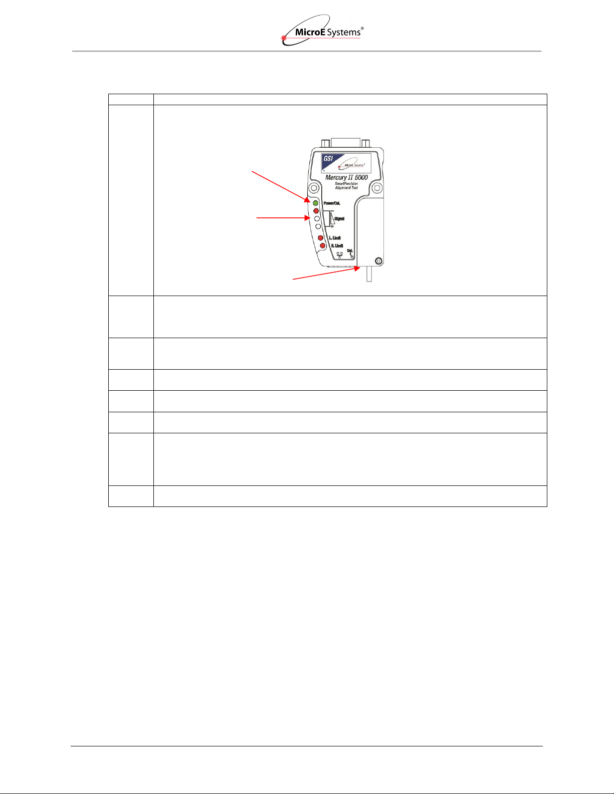
Mercury II 5000 Alignment Tool LEDs
LED
Function
Power/Cal.
Indicates power is on and when in
alignment mode
Red Signal Strength
Indicates improper alignment
Yellow Signal Strength
Indicates improved alignment
Green Signal Strength
Indicates proper alignment
Left Limit
Blinks in Alignment Mode and when
sensor is located over left limit
Right Limit
Blinks in Alignment Mode and when
sensor is located over right limit
Power/Cal. LED
15 Pin D-Sub
Sensor Connector
Left Limit LED
Cal. Pushbutton
Ethernet Connector
Alignment Tool
Adapter
Red Signal Strength LED
Yellow Signal Strength LED
Green Signal Strength LED
Right Limit LED
Alignment Tool
Power Supply
Connect
3.3 SmartPrecision Alignment Tool
The Mercury II ATMII5000 SmartPrecision Alignment Tool is required for aligning the Mercury II
6000 Series Encoders. The Alignment Tool includes the following:
Alignment Tool
SmartPrecision II Software
USB Cable
Power Supply
For more details, see Sensor Installation Tools in Appendix 8.0 Order Guide.
IM-Mercury_II_6000 Series Rev. 1 Page 6 ©2014 MicroE Systems
Sensor Installation
Mercury II 6000 Series Encoders
Installation Manual and Reference Guide
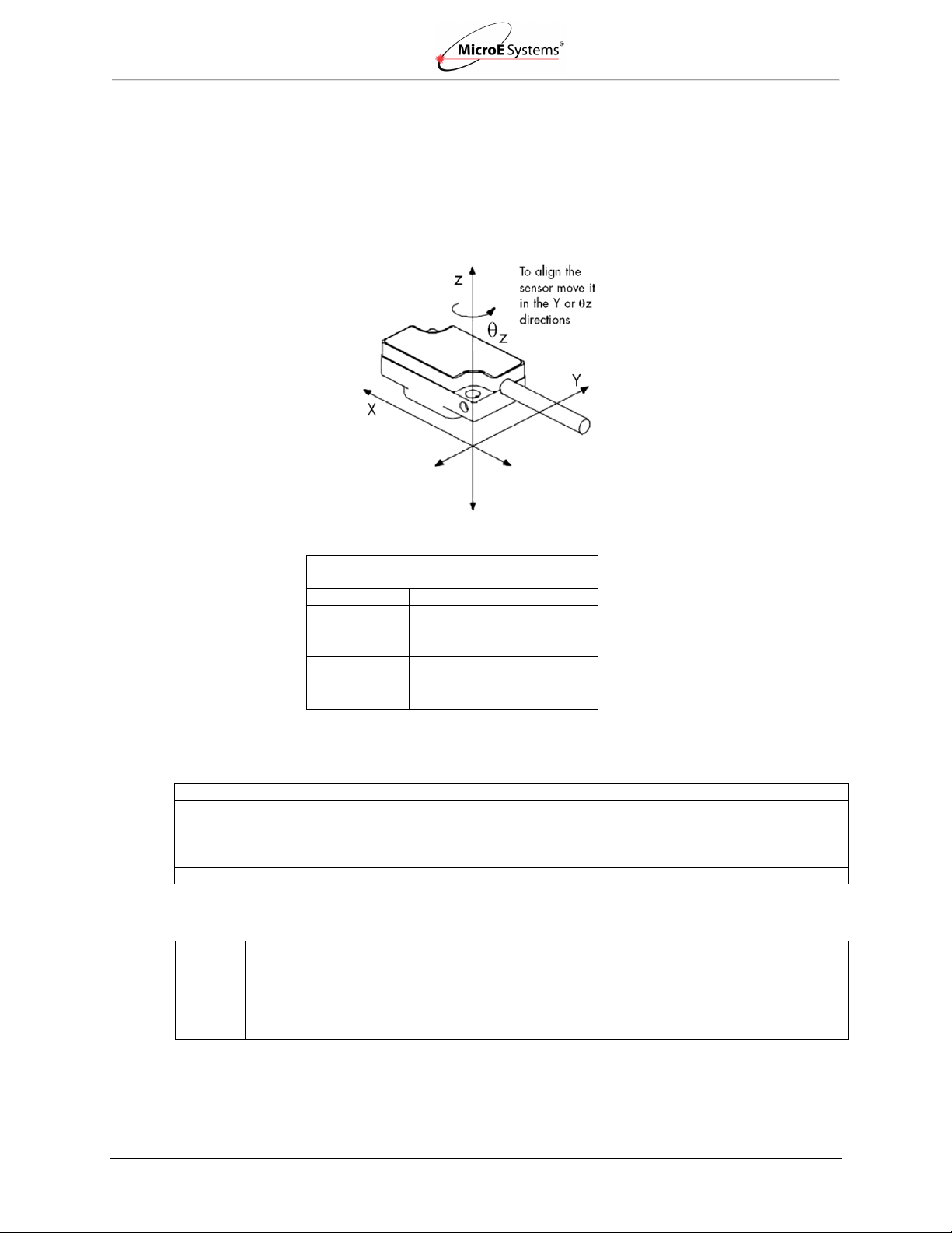
Orientation
Tolerances
Mercury II
Sensor Alignment Tolerances
Axis
Alignment Tolerance
X
Direction of Motion
Y
± 0.20mm
Z
± 0.15mm
X
± 1.0°
Y
± 1.0°
Z
± 2.0°
Step
Action
1.
Verify that the vertical distance between the reference surface of the sensor and the top of the
scale is as follows:
Tape scale/marker tape after blue protective film is removed: 3.09 mm +/-0.13
Linear or rotary glass scales: 2.93 mm +/-0.13
2.
Check the height at a location on the scale where there are no index or limit markers.
Step
Action
1.
Install the sensor on the mounting surface referencing the appropriate datum surface as
shown in the MII6000 Interface Drawings. Use two M-2 screws to loosely attach the sensor.
Note: Do not tighten the two M2 screws at this time.
2.
Use benching pins to locate the sensor if the system's mechanical tolerances are adequate.
Refer to the MII6000 Interface Drawings for recommended locations and heights of pins.
Sensor Axes
4.0 Sensor Installation
This section contains instructions for installing the sensor.
4.1 Sensor Mounting Orientation and Tolerances
Refer to the following specifications when installing and aligning the Mercury II 6000 encoder.
4.2 Verify Sensor Mounting Surface Height
4.3 Install Sensor
IM-Mercury_II_6000 Series Rev. 1 Page 7 ©2014 MicroE Systems
Sensor Alignment and Calibration
Mercury II 6000 Series Encoders
Installation Manual and Reference Guide
Method
Description
1.
Use the Calibration (Cal.) Pushbutton:
Align and calibrate the sensor head using the Calibration (Cal.) pushbutton and the LED
indicators on the Alignment Tool.
Continue to Section 5.1 Using the Cal. Pushbutton.
2.
Use the SmartPrecision II Software*:
Align and calibrate the sensor head using the Alignment Tool and the SmartPrecision II
Software.
Continue to Section 5.2 Using the Software.
Note*: The SmartPrecision II Software is built in to the Alignment Tool ATMII5000
for setup and diagnostics; only a web browser is needed (use of software is
optional). See the Sensor Installation Tools in Appendix 8.0 Order Guide for
details.
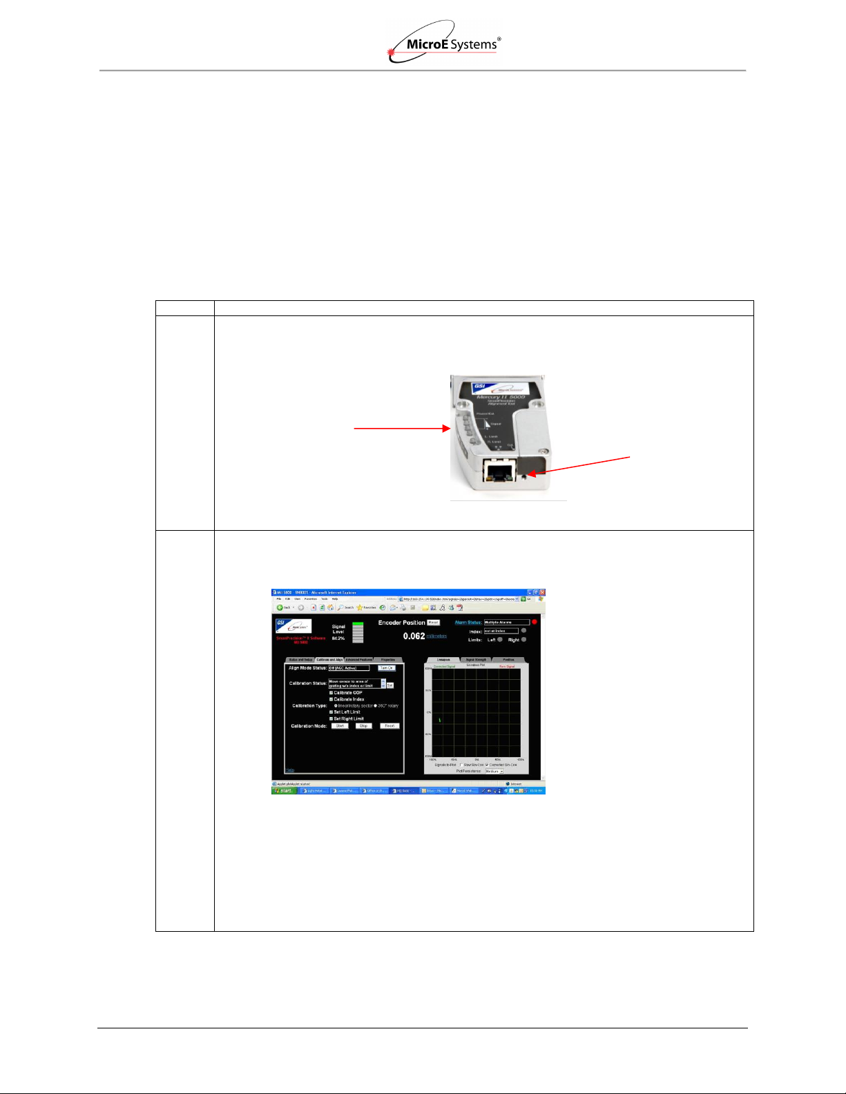
Access to Cal.
Pushbutton
Alignment Tool
LED Indicators
SmartPrecision II Screen
5.0 Sensor Alignment and Calibration
After installing the MII6000 encoder, use the SmartPrecision Alignment Tool ATMII5000 to align
and calibrate the sensor using one of the following methods:
Calibration (Cal.) Pushbutton: if you don’t have access to a computer or are very
experienced at performing encoder alignment and calibration.
SmartPrecision II Software: if you have access to a computer and either are new at
performing encoder alignment and calibration or want to take advantage of the graphic
interface.
Select a method:
IM-Mercury_II_6000 Series Rev. 1 Page 8 ©2014 MicroE Systems
Sensor Alignment and Calibration
Mercury II 6000 Series Encoders
Installation Manual and Reference Guide
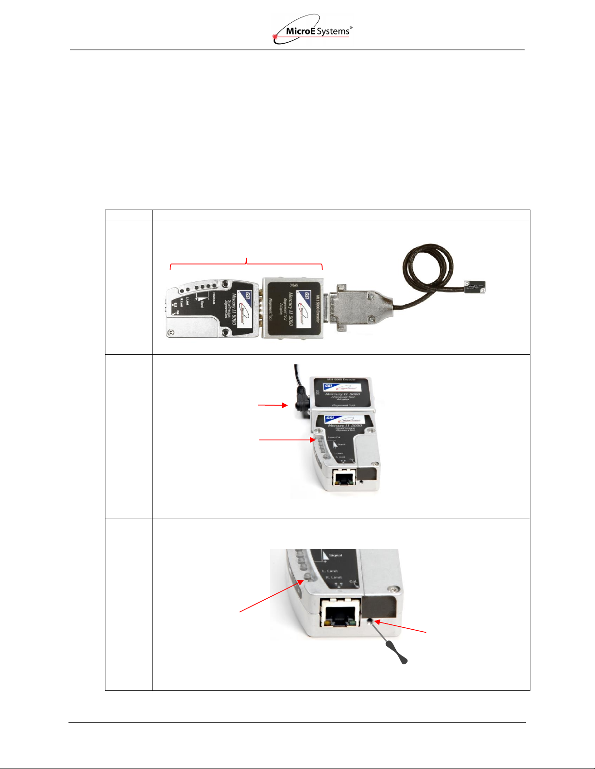
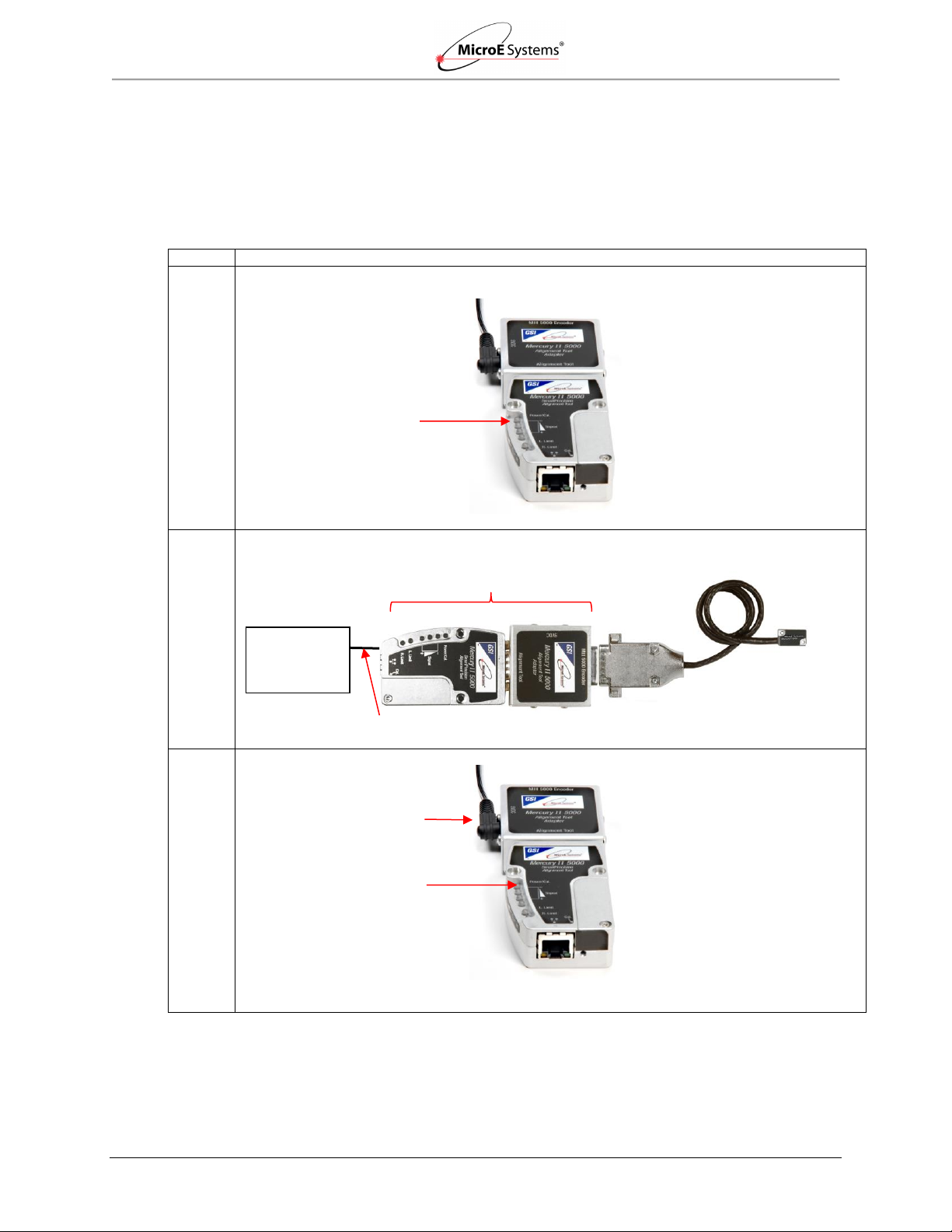
Step
Action
1.
Connect the MII6000 encoder to the SmartPrecision Alignment Tool.
2.
Insert the 5VDC power connector to the Alignment Tool Adapter and apply power.
Result: The Power/Cal. LED illuminates a steady green. The sensor is initialized after an
approximate 10 second delay.
3.
Enter the Alignment Mode by gently pressing and releasing the Cal. pushbutton quickly (within
a second) using a small screwdriver or similar tool.
Result: The two Limit LEDs will begin to blink in unison (slowly). Automatic Gain Control
(AGC) is now inactive. The AGC adjusts gain to maintain a steady signal level.
Alignment Tool
5VDC Power
Alignment Tool Adapter
Encoder
Sensor Connector
Alignment Tool
Power/Cal. LED
Access to Cal.
Pushbutton
Limit LEDs (two)
Screwdriver
5.1 Using the Cal. Pushbutton
Use the following instructions to perform sensor alignment and calibration by using the Cal.
Pushbutton located on the ATMII5000 Alignment Tool.
5.1.1 Sensor Alignment
Note: Make sure that the 5VDC power input is disconnected. Encoder should never be
connected to an already energized alignment tool since equipment can be damaged.
IM-Mercury_II_6000 Series Rev. 1 Page 9 ©2014 MicroE Systems
Sensor Alignment and Calibration
Mercury II 6000 Series Encoders
Installation Manual and Reference Guide
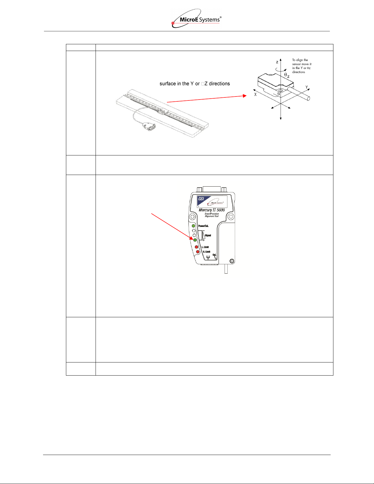
Step
Action
4.
Align the sensor by slowly sliding the sensor on its
mounting surface in the Y or Z directions until the green
Signal Strength LED is illuminated*.
Note*: Optimal alignment is indicated by Bright Green.
5.
Once the sensor is aligned, tighten the two sensor mounting screws (0.37Nm [3.3 inch-lbs.]
maximum torque).
6.
Move the sensor over the index mark and confirm that the green Signal Strength LED blinks.
Result:
If the green Signal Strength LED blinks when the sensor passes over the index, then
proceed to the next step.
If the green Signal Strength LED does not blink when the sensor passes over the index,
then loosen the mounting screws and repeat the alignment procedure (go back to Step 3).
Note*: Optimal alignment is indicated by Bright Green and a blink over the index.
7.
Move the sensor over the entire length of the scale.
Result:
If the green Signal Strength LED remains illuminated over the entire length of travel (the
yellow and red LED’s do not illuminate), then proceed to the next step.
Otherwise, clean the scale and try Step 3 again. If cleaning the scale is not successful,
loosen the sensor mounting screws and repeat the alignment procedure (go back to
Step 3).
8.
Press and release the Cal. button quickly to exit Alignment Mode.
Result: The limit LED’s will stop blinking and AGC will reactivate.
Slowly slide sensor on its mounting
Green Signal Strength LED
(Proper Alignment)*
IM-Mercury_II_6000 Series Rev. 1 Page 10 ©2014 MicroE Systems
Sensor Alignment and Calibration
Mercury II 6000 Series Encoders
Installation Manual and Reference Guide
5.1.2 Sensor Calibration
Perform calibration when installing the sensor for first time, or if the sensor is subsequently
remounted, or the scale is replaced. This section contains instructions for calibrating the
following:
Linear Scales or Rotary Scales used in applications less than <360°
Rotary Scales used in applications less than >360° without Limit Markers
Confirm Settings
Confirm the following before calibration:
Always perform calibration of the left and right limits while Limit Polarity is set to Limits
Normal mode. See the Left and Right Limits Settings in the Calibration and Align tab of
the SmartPrecision II Software in Section 5.2.3 Sensor Alignment and Calibration.
Select correct Reflective or Non-Reflective Grating Type on Status and Setup tab.
IM-Mercury_II_6000 Series Rev. 1 Page 11 ©2014 MicroE Systems

Sensor Alignment and Calibration
Mercury II 6000 Series Encoders
Installation Manual and Reference Guide
Step
Action
1.
To start calibration, press and hold the Cal. button for about two seconds until the Power/Cal.
LED starts blinking slowly.
2.
Move the sensor 50mm to perform Gain/Offset/Phase calibration. Move the sensor back and
forth if scale has <50mm of measuring length.
Result: After calibration both limit LEDs come on steady.
3.
Move the sensor to an area of the scale away from the index and limit markers. Press the Cal.
button once quickly.
Result: The Power/Cal. LED will start blinking quickly.
4.
Move the sensor over the index up to 20 passes (one pass is a single cycle back and forth).
Result: The Left Limit LED will start blinking quickly.
Note: If the sensor is positioned over the left limit marker, the Left Limit LED will come on
steady.
5.
Move the sensor over the left limit marker and press the Cal. button once quickly.
Result: The Right Limit LED will start blinking.
Note: if the sensor is positioned over the right limit marker, the Right Limit LED will come on
steady.
6.
Move the sensor over the right limit marker and press the Cal. button once quickly.
Result: All LEDs will flash together twice to indicate that setup is completed.
The encoder is now ready for connection to the controller for use in servo control.
7.
When calibration is complete, go to Section 6.0 Alignment Verification with Connector
LEDs to visually verify calibration using the LED indicators on the MII6000 sensor’s connector.
Power/Cal. LED
Cal. Pushbutton
Limit Switches LEDs
Note: Perform all procedures below at ≤1 meter/second relative motion between the sensor and
the scale.
Linear Scales or Rotary Scales used in applications less than <360°
Note: To skip any portion of this calibration and move to the next procedure, press and hold the
Cal. button for two seconds.
IM-Mercury_II_6000 Series Rev. 1 Page 12 ©2014 MicroE Systems
Sensor Alignment and Calibration
Mercury II 6000 Series Encoders
Installation Manual and Reference Guide
Step
Action
1.
To start calibration, press and hold the Cal. button for about 10 seconds: until the three Signal
LEDs blink twice to indicate that rotary calibration has been activated.
2.
Move the sensor 50mm to perform Gain/Offset /Phase calibration. After calibration both limit
LED’s come on steady. Move the sensor back and forth if your scale has a circumference of
<50mm.
Result: After calibration both limit LEDs come on steady.
3.
Move the sensor to an area of the scale away from the index marker. Press the Cal. button
once quickly.
Result: The Power/Cal. LED will start blinking quickly.
4.
Move the sensor over the index up to 20 passes (one pass is a single cycle back and forth).
Result: The Power/Cal. LED and both limit LEDs will start to blink in sets of three.
5.
Move the sensor away from the index and press the Cal. button once quickly.
Result: The Power/Cal. LED and both limit LED’s will start to blink in sets of two.
6.
Move the sensor over the index once.
Result: The LEDs will change to Power/Cal. LED and both limit LEDs blinking just once.
7.
Make a full revolution of the rotary scale in order to go over the index again in the same
direction. The two passes over the index must be at least 1000 20µm fringes apart (equivalent
of 20mm linear travel), if they are not, the Alignment Tool will wait for another pass that is 1000
fringes from the first.
Result: The encoder is now ready for connection to the controller for use in servo control.
8.
When calibration is complete, go to Section 6.0 Alignment Verification with Connector
LEDs to visually verify calibration using the LED indicators on the MII6000 sensor’s connector.
Signal LEDs (3)
Cal. Pushbutton
Power/Cal. LED
Rotary Scales used in applications less than >360° without Limit Markers
Note: To skip any portion of` this calibration and move on to the next procedure, press and hold
the Cal. button for two seconds.
IM-Mercury_II_6000 Series Rev. 1 Page 13 ©2014 MicroE Systems
Sensor Alignment and Calibration
Mercury II 6000 Series Encoders
Installation Manual and Reference Guide
Step
Action
1.
Verify that the Alignment Tool Adapter/SmartPrecision II Alignment Tool is not powered on. The
Power/Cal. LED should be off.
2.
Connect the MII 6000 encoder and Ethernet cable as shown below.
3.
Power up the Alignment Tool by plugging in 5VDC to the Alignment Tool Adapter.
Result: The Power/Cal. LED illuminates a steady green. The sensor is initialized after an
approximate 10 second delay.
5VDC Power
Alignment Tool Adapter
Power/Cal. LED
Power/Cal. LED
Alignment Tool
Encoder
Ethernet Cable
Sensor Connector
Computer
(Windows or
other OS)
5.2 Using the Software
Use the following instructions to perform sensor alignment and calibration using the Alignment
Tool and the SmartPrecision II Software.
5.2.1 Connect the Alignment Tool and Encoder
IM-Mercury_II_6000 Series Rev. 1 Page 14 ©2014 MicroE Systems
Sensor Alignment and Calibration
Mercury II 6000 Series Encoders
Installation Manual and Reference Guide
Step
Action
1.
Once the encoder is connected to the computer using an Ethernet cable, run the software
program FindMII (Mercury II Encoder Search Utility) version 1.2.2.1 or higher. To locate the
correct version for your operating system, go to Software Downloads at
http://www.microesys.com/products/documentation or click on one of the following links:
For Windows operating systems:
FindMII.exe
For all other operating systems:
FindMII.jar
2.
The FindMII program locates the encoder and allows you to use the embedded SmartPrecision II
Software on your web browser.
Note: You may receive an Application Blocked by Security Settings message when
attempting to load the plotApplet. Go to the Java applet in your Control Panel and try reducing
the Security Level in the Security Tab.
Warning: Reducing the Security Level in the Security Tab may decrease protection of your
computer against malicious software.
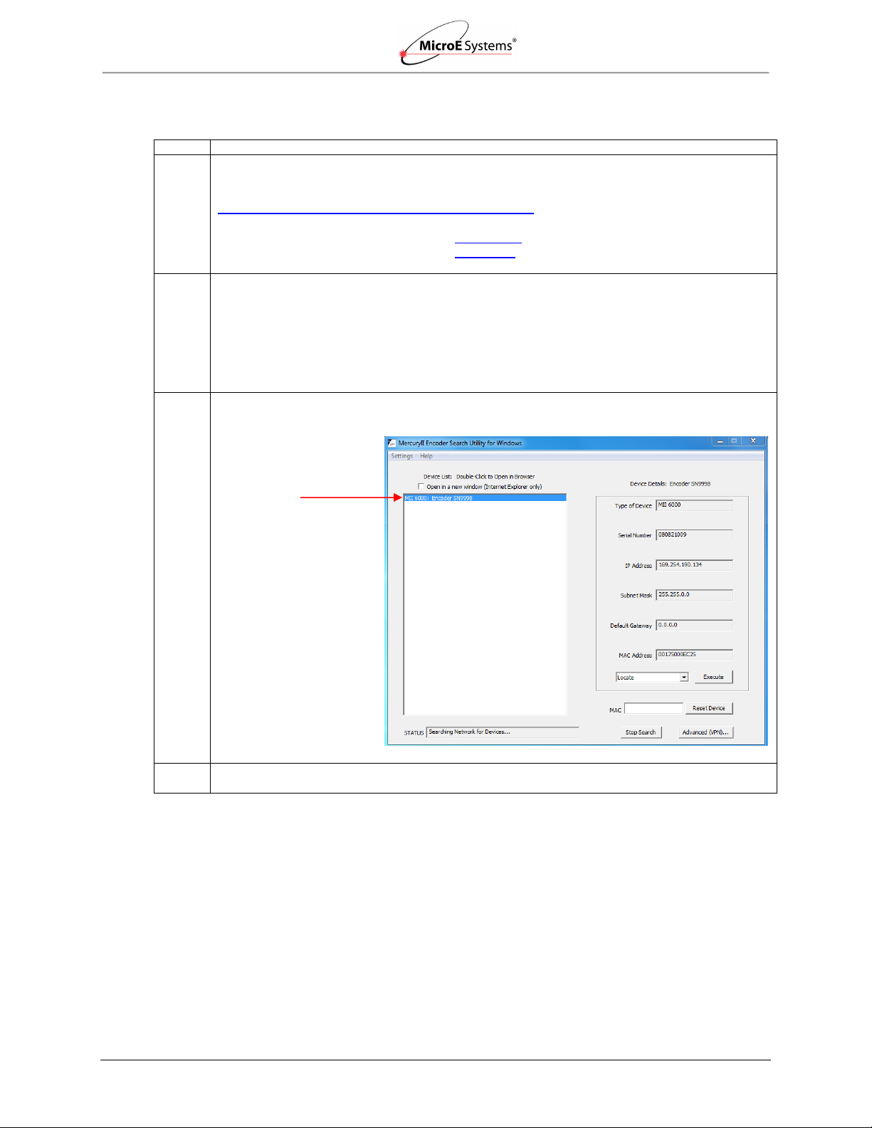
3.
Once located, the FindMII program will list all the encoders connected to the network as seen in
the following example.
4.
Double-click the name of the encoder to open the SmartPrecision II Software.
Encoder
found by the
program
5.2.2 Use the FindMII Program to locate the Encoder
IM-Mercury_II_6000 Series Rev. 1 Page 15 ©2014 MicroE Systems
Sensor Alignment and Calibration
Mercury II 6000 Series Encoders
Installation Manual and Reference Guide
Step
Action
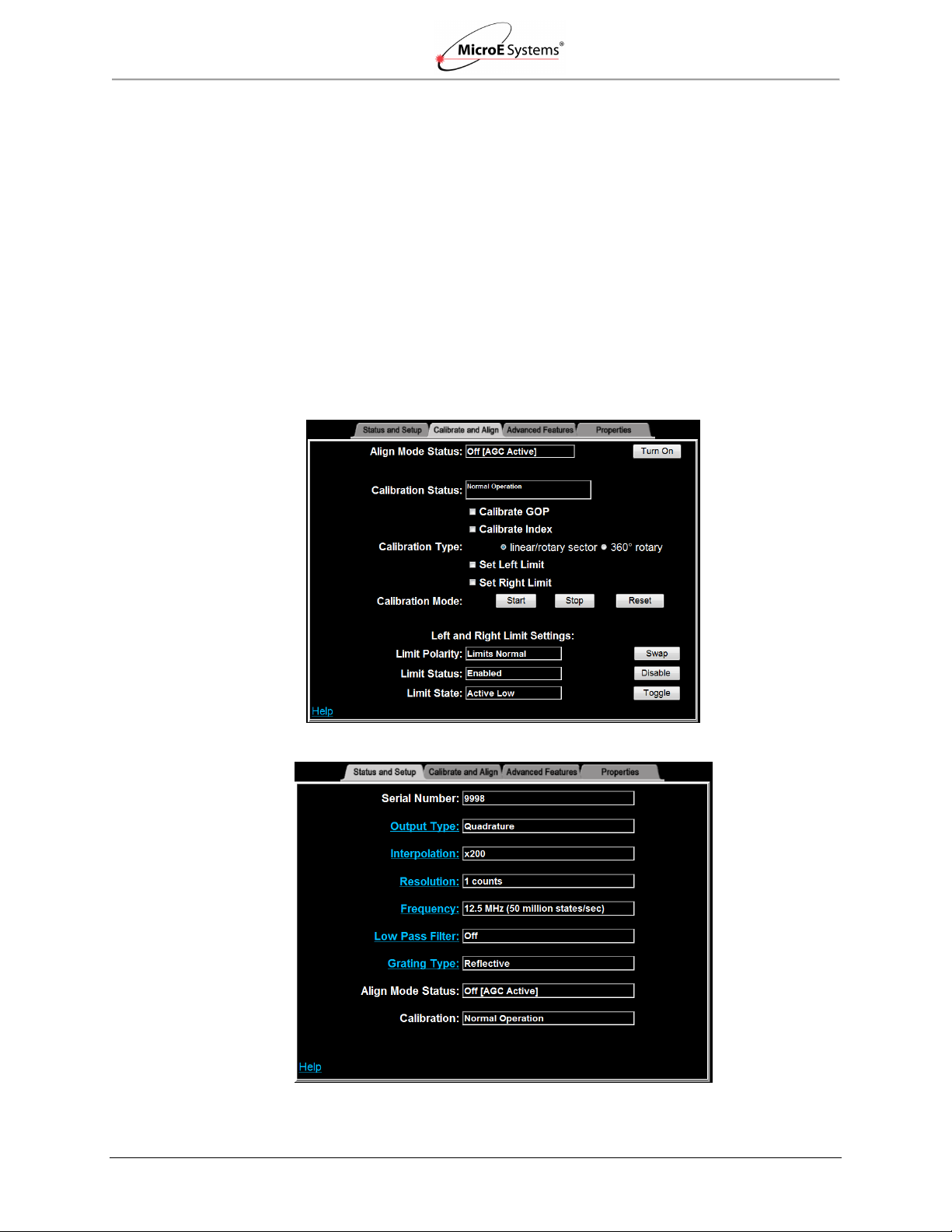
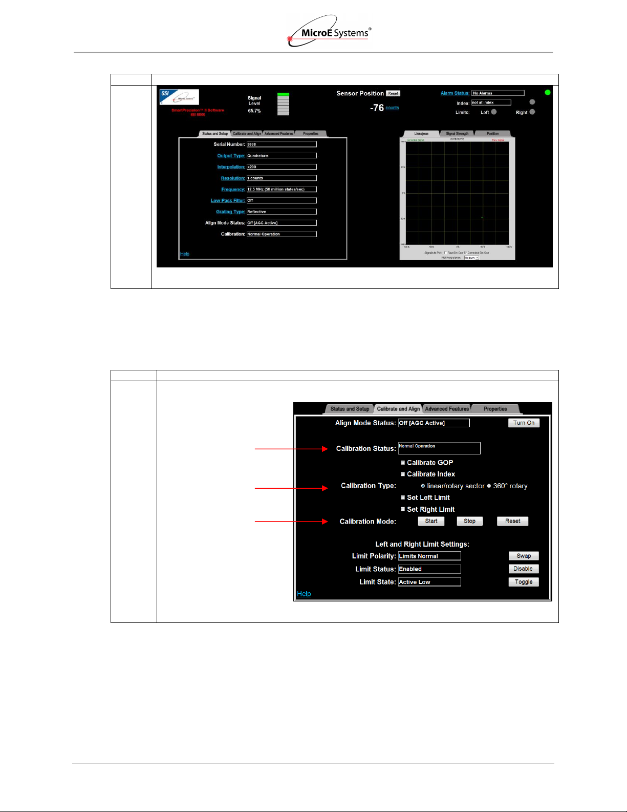
Results: The SmartPrecision II Software Screen opens.
Step
Action
1.
Click on the Calibrate and Align tab.
Results: The Calibrate and Align screen opens.
Calibrate and Align Tab
Calibration Status
Calibration Type
Calibration Mode
5.2.3 Sensor Alignment and Calibration
Once the SmartPrecision II Software is open, perform sensor alignment and calibration by using
the Calibrate and Align tab.
IM-Mercury_II_6000 Series Rev. 1 Page 16 ©2014 MicroE Systems
Sensor Alignment and Calibration
Mercury II 6000 Series Encoders
Installation Manual and Reference Guide
Step
Action
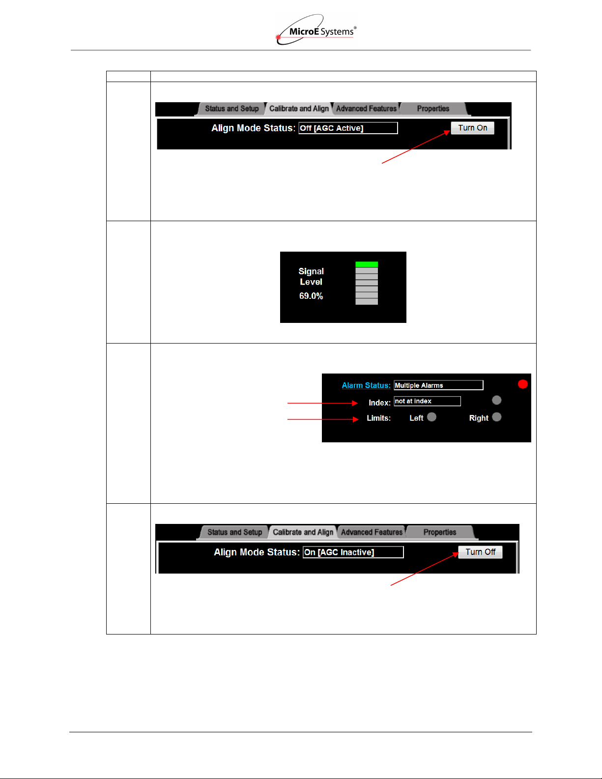
2.
Turn on Align Mode by clicking on the Align Mode Turn On button.
Results: The Turn On button will change to Turn Off. Align Mode Status will change to On
(AGC Inactive). On the Alignment Tool, both Left and Right Limit LEDS will begin blinking.
3.
Adjust the sensor position until the maximum signal strength is achieved. See the Signal Level
Indicator at the top of the SmartPrecision screen.
4.
Tighten the sensor mounting screws. Check for index indication (using the status display at the
top right of the screen).
Results: The Index indication is “not at index” when the sensor is not located at the Index
marker, and “index crossed” when the sensor has passed over the Index marker.
5.
Turn off Align Mode by clicking on the Align Mode Turn Off button.
Result: The Turn Off button will change to Turn On. Align Mode Status will change to Off
(AGC Active). On the Alignment Tool, both Left and Right Limit LEDS will stop blinking.
Signal Level Indicator
Align Mode Turn On/Off Button
Index Indication
Align Mode Turn On/Off Button
Limits Indication
IM-Mercury_II_6000 Series Rev. 1 Page 17 ©2014 MicroE Systems
Sensor Alignment and Calibration
Mercury II 6000 Series Encoders
Installation Manual and Reference Guide
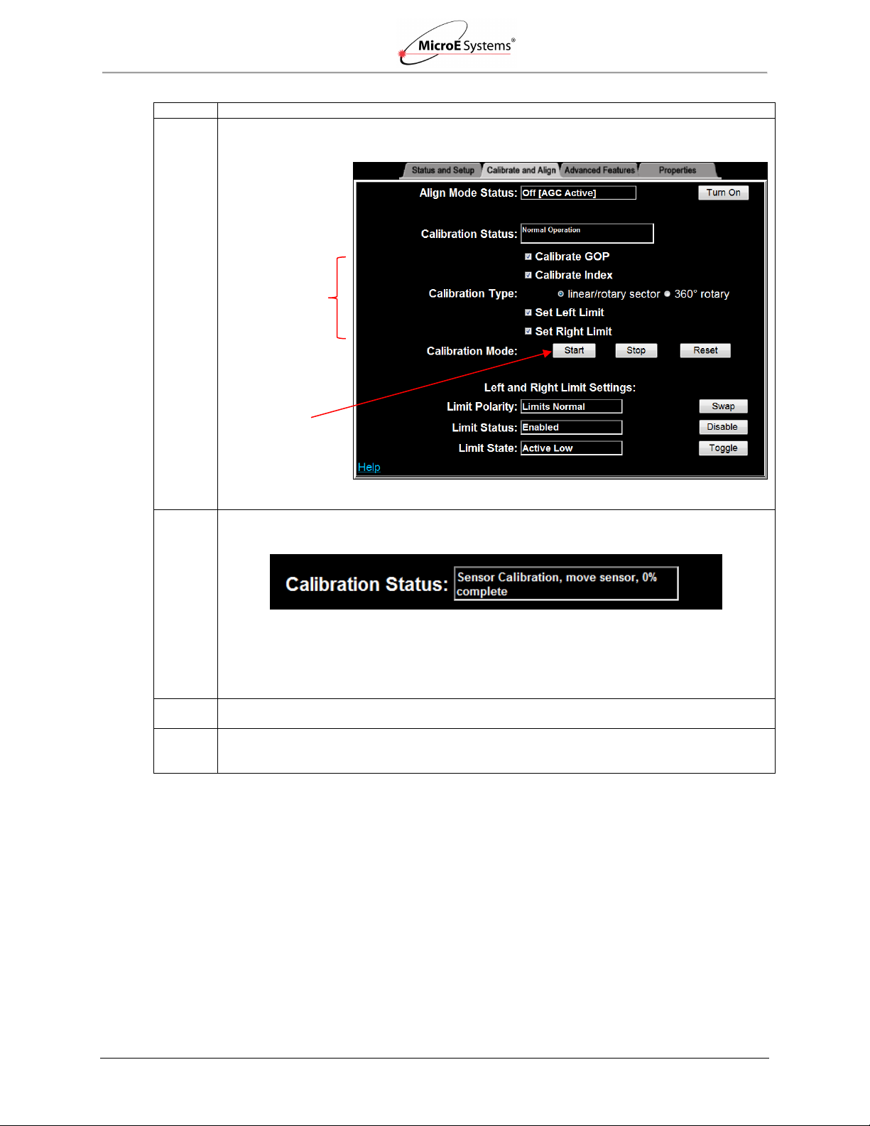
Step
Action
6.
Perform setup by checking the Calibrate GOP, Calibrate Index, Set Left Limit, and Set Right
Limit boxes.
Note: Not all applications require all steps.
7.
Ensure that the Calibration Type is correctly selected for your encoder (linear/rotary sector is
selected above). Press the Start button in Calibration Mode to begin calibration/setup.
Results: Sensor Calibration will begin. Follow the steps in the Calibration Status box to
complete setup of the MII6000 encoder. For example, in the status box above, the instructions
are to move the sensor until reaching 100% complete and then the next calibration step will
start.
8.
If there is a failure, turn off the sensor and clean the scale. After cleaning, return to Section
5.2.3 Sensor Alignment and Calibration.
9.
When calibration is complete, continue to the next section Alignment Verification with
Connector LEDs to visually verify calibration using the LED indicators on the MII6000 sensor’s
connector.
Start Button
Check Boxes
IM-Mercury_II_6000 Series Rev. 1 Page 18 ©2014 MicroE Systems
Alignment Verification with Connector LEDs
Mercury II 6000 Series Encoders
Installation Manual and Reference Guide
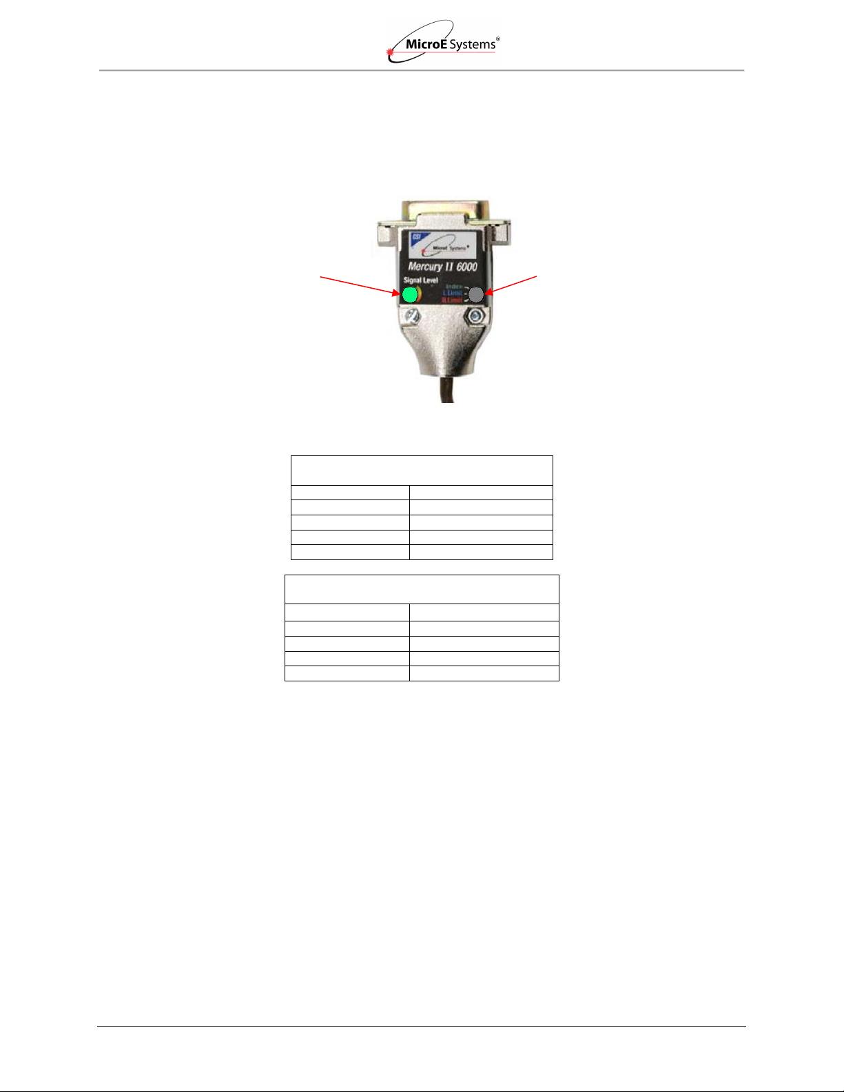
Mercury II Sensor Connectors
LED Indicators – Signal Strength
Color
Signal Strength
Green
Optimal
Yellow
Marginal
Red
Bad
Purple
Saturated
Mercury II Sensor Connectors
LED Indicators – Limit/Index Markers
Color
Limit/Index Mark
Green
Over Index Mark
Blue
Over Left Limit Mark
Red
Over Right Limit Mark
None
Not Over Any Mark
Signal Level LED indicates
signal strength of main track
(green is optimal)
Limit/Index LED Indicates presence of
left limit mark, right limit mark, or index
mark (no color indicates sensor not
positioned over any marks)
6.0 Alignment Verification with Connector LEDs
Once the encoder is aligned and calibrated using the alignment tool, alignment can be visually
verified using the LED indicators on the MII6000 sensor’s connector.
Sensor Connector display (shown during normal operation):
Color Codes for Indicators
IM-Mercury_II_6000 Series Rev. 1 Page 19 ©2014 MicroE Systems

Appendix
Mercury II 6000 Series Encoders
Installation Manual and Reference Guide
System
Sensor Size
Scales
PurePrecision Marker Tape or Laser Tape scales available in continuous lengths up to 30m.
Linear glass scales for high accuracy.
Rotary glass scales for rotary applications.
H: 8.23mm
W: 12.70mm
L: 22.61mm
Operating and Electrical Specifications
Grating Period
20µm
Agency Standards Conformance: In accordance with
Electromagnetic Compatibility Directive 2004/108/EC:
EN 55011:2007, EN 61000-4-2, -3, -6
Signal Period
20µm
SPI Interface Clock Speed: 25MHz - 50MHz
Max Sample Rate: 227,272 position reads/s - 50MHz clock
System
Resolution
5µm - 0.00122µm* in integer
interpolation steps (factory set or
user programmed using included
SmartPrecision II Software.
Power Supply: 5VDC ±5%
*Value rounded for readability. Use the formula
20µm/interpolation multiplier to calculate the
exact resolution in units of µm/count.
Note: MII6800Pa resolution is fixed at 1.22nm.
@
@
140mA (no outputs terminated)
180mA (A, B, I, and both limits
terminated); 50mA at the sensor
(MII6500/MII6700/MII6800)
Accuracy/Linearity
Cyclical Error
@
172mA (all serial I/O connections
terminated); 50mA at the sensor
(MII6800Si/Pa)
Tape
Scales:
Glass
Scales:
± 30nm typical over any 20µm
movement
± 20nm typical over any 20µm
movement
Temperature
Operating:
Storage:
0°C to 70°C
-20°C to 85°C
Tape Scale
Linearity:
± 5µm/m
Humidity:
10 - 90% RH non-condensing
Glass Scale Accuracy
EMI
CE Compliant
High Accuracy
Grade:
±1µm for scales up to 130mm
±2µm for scales from130mm to 1m
Shock:
300G 0.5 ms half sine (Sensor)
Vibration:
30G @ 17Hz
Sensor
Weight:
3g (Sensor without cable)
Standard
Accuracy
Grade:
±1.5µm for scales up to 130mm
±5µm for scales from 130mm to
1m
Cable:
Double Shield
Maximum length: 10m (contact MicroE
Systems for applications >5m)
Diameter: 4.2mm
Flex Life: 20 x 106 cycles @ 20mm
bending radius
Note: Accuracy is the maximum error over the
specified movement when compared to a
NIST-traceable laser interferometer standard
used at room temperature.
Rotary
Accuracy*
Scale O.D.
Microradians
Arc-
Seconds
Reliability Information
5 Year Expected Reliability: >99.8% under normal
operating conditions.
44.45mm
± 38
± 7.8
63.50mm
± 19
± 3.9
120.65mm
± 10
± 2.1
Note: *Based on ideal scale mounting concentricity.
Index: Built-in or stick-on; bi-directional, full speed.
Note: After power up, the index mark must be passed once at 1 m/s for proper operation.
Limits: Separate built-in or stick-on left and right limits.
Laser-written embedded index and limits available. Contact MicroE.
7.0 Appendix
7.1 Specifications
IM-Mercury_II_6000 Series Rev. 1 Page 20 ©2014 MicroE Systems
Appendix
Mercury II 6000 Series Encoders
Installation Manual and Reference Guide
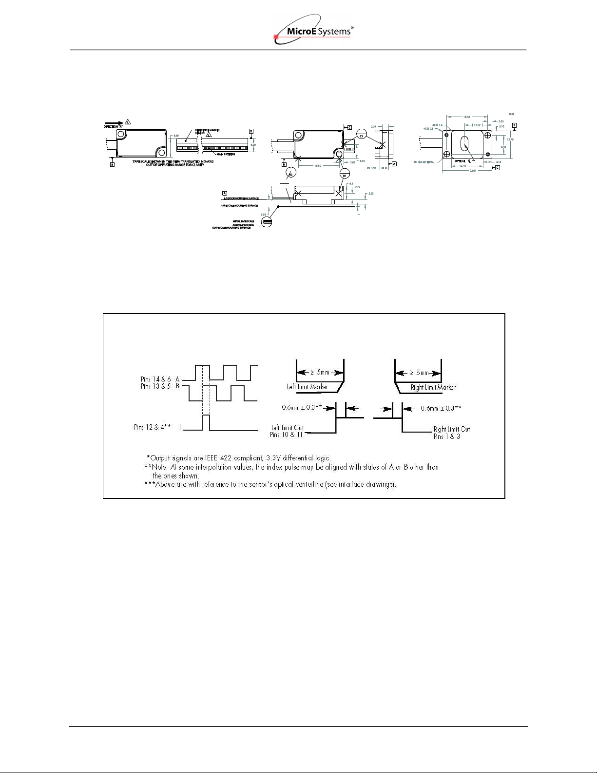
Quadrature*
Limits*
Note: Sensor below shown with tape scale. Refer to the MII6000 Interface Drawings for additional dimensional
details and important notes.
MII6000 Output Signals
IM-Mercury_II_6000 Series Rev. 1 Page 21 ©2014 MicroE Systems

Appendix
Mercury II 6000 Series Encoders
Installation Manual and Reference Guide
Maximum
Interpolation
Resolution
Maximum
Speed*
Applicable Models
x 4
5.000µm/count
10000mm/sec
6500, 6700, 6800
x 10
2.000µm/count
10000mm/sec
6500, 6700, 6800
x 20
1.000µm/count
10000mm/sec
6500, 6700, 6800
x 40
0.500µm/count
10000mm/sec
6500, 6700, 6800
x 80
0.250µm/count
10000mm/sec
6500, 6700, 6800
x 100
0.200µm/count
10000mm/sec
6500, 6700, 6800
x 200
0.100µm/count
5000mm/sec
6500, 6700, 6800
x 400
0.050µm/count
2500mm/sec
6500, 6700, 6800
x 1000
20.0nm/count
1000mm/sec
6700, 6800
x 2000
10.0nm/count
500mm/sec
6700, 6800
x 4000
5.00nm/count
250mm/sec
6700, 6800
x 8000
2.50nm/count
125mm/sec
6800
x 16384
1.22nm/count†
61mm/sec
6800
7.2 Resolution and Maximum Speed Tables
Resolution and Maximum Speed Tables - Quadrature Output
Mercury II 6000 systems (models 6500/6700/6800) have programmable interpolation from x4 to
x16384 in integer steps. Below are tables of sample values. For applications requiring up to
10m/s at full resolution, use the MII6800Si/Pa with high speed serial interface.
Linear – 20µ Grating Pitch
Note: †Value rounded for readability; use the following formula to calculate the exact resolution
in units of µm/count:
𝑅𝑒𝑠𝑜𝑙𝑢𝑡𝑖𝑜𝑛 =
𝐼𝑛𝑡𝑒𝑟𝑝𝑜𝑙𝑎𝑡𝑖𝑜𝑛 𝑀𝑢𝑙𝑡𝑖𝑝𝑙𝑖𝑒𝑟
20µ
IM-Mercury_II_6000 Series Rev. 1 Page 22 ©2014 MicroE Systems

Appendix
Mercury II 6000 Series Encoders
Installation Manual and Reference Guide
Rotary
Glass
Scale
Diameter
Fundamental
Resolution
Interpolation
44.45mm
5000 Lines
x4
x20
x40
x400
x1000
x4000
x16384
interpolated resolution (CPR)
20000
100000
200000
2000000
5000000
20000000
81920000
interpolated resolution (arcsec/count)**
64.8
12.96
6.48
0.648
0.259
0.0648
0.01582
interpolated resolution
(µrad/count)**
314
62.8
31.4
3.14
1.257
0.314
0.0767
maximum speed* (RPM)
6000
6000
6000
1500
600
150
36.6
63.50mm
8192 Lines
interpolated resolution (CPR)
32768
163840
327680
3276800
8192000
32768000
134217728
interpolated resolution (arcsec/count)**
39.6
7.91
3.96
0.396
0.1582
0.0396
0.00966
interpolated resolution
(µrad/count)**
191.7
38.3
19.17
1.917
0.767
0.1917
0.0468
maximum speed* (RPM)
3660
3660
3660
915
366
91.5
22.3
120.65mm
16384 Lines
interpolated resolution (CPR)
65536
327680
655360
6553600
16384000
65536000
268435456
interpolated resolution (arcsec/count)**
19.78
3.96
1.978
0.1978
0.0791
0.01978
0.00483
interpolated resolution
(µrad/count)**
95.9
19.17
9.59
0.959
0.383
0.0959
0.0234
maximum speed* (RPM)
1830
1830
1830
457
183.1
45.7
11.17
Applicable Models
6500,
6700,
6800
6500,
6700, 6800
6500,
6700,
6800
6700, 6800
6700,
6800
6800
6800
Rotary – 20µ Grating Pitch
Interpolation Note: The range of available values is x4 to x16384 in integer steps; sample values
below.
Note: *Maximum speed produces an encoder quadrature output of 50 million states per second
(12.5MHz). See Page 24 for additional output frequencies. Maximum speeds shown above will be
reduced if a lower quadrature output frequency is selected.
Note: **Resolution values shown are approximate. To calculate exact resolution values, convert from
CPR (Counts per Revolution) to the desired units.
Note: To calculate desired rotary interpolation multiplier, use the following equation:
𝐼𝑛𝑡𝑒𝑟𝑝𝑜𝑙𝑎𝑡𝑖𝑜𝑛 𝑀𝑢𝑙𝑡𝑖𝑝𝑙𝑖𝑒𝑟 =
𝐷𝑒𝑠𝑖𝑟𝑒𝑑 𝑅𝑒𝑠𝑜𝑙𝑢𝑡𝑖𝑜𝑛 (𝐶𝑃𝑅)
𝐹𝑢𝑛𝑑𝑎𝑚𝑒𝑛𝑡𝑎𝑙 𝑆𝑐𝑎𝑙𝑒 𝑅𝑒𝑠𝑜𝑙𝑢𝑡𝑖𝑜𝑛 (𝐿𝑖𝑛𝑒𝑠)
Note: Specifications assume XOR function which is available in all standard controllers.
IM-Mercury_II_6000 Series Rev. 1 Page 23 ©2014 MicroE Systems

Appendix
Mercury II 6000 Series Encoders
Installation Manual and Reference Guide
Interpolation
Multiplier
Interpolation
Bits
Resolution
Maximum Speed
x 4
2
5.000µm/count
10000mm/sec
x 8
3
2.500µm/count
10000mm/sec
x 16
4
1.250µm/count
10000mm/sec
x 32
5
0.6250µm/count
10000mm/sec
x 64
6
0.3125µm/count
10000mm/sec
x 128
7
0.15625µm/count
10000mm/sec
x 256
8
0.078125µm/count
10000mm/sec
x 512
9
0.0390625µm/count
10000mm/sec
x 1024
10
19.53125nm/count
10000mm/sec
x 2048
11
9.765625nm/count
10000mm/sec
x 4096
12
4.8828125nm/count
10000mm/sec
x 8192
13
2.44140625nm/count
10000mm/sec
x 16384
14
1.220703125nm/count
10000mm/sec
Rotary Glass
Scale Diameter
Fundamental Resolution
Interpolation
44.45mm
5000 Lines
x4
x1024
x4096
x16384
interpolated resolution (CPR)
20000
5120000
20480000
81920000
interpolated resolution (arcsec/count)*
64.8
0.253
0.0630
0.01582
interpolated resolution (µrad/count)*
314
1.23
0.306
0.0767
maximum speed (RPM)
6000
6000
6000
6000
63.50mm
8192 Lines
x4
x1024
x4096
x16384
interpolated resolution (CPR)
32768
8388608
33554432
134217728
interpolated resolution (arcsec/count)*
39.6
0.154
0.038
0.00966
interpolated resolution (µrad/count)*
191.7
0.749
0.187
0.0468
maximum speed (RPM)
3660
3660
3660
3660
120.65mm
16384 Lines
x4
x1024
x4096
x16384
interpolated resolution (CPR)
65536
16777216
67108864
268435456
interpolated resolution (arcsec/count)*
19.78
0.0772
0.01978
0.00481
interpolated resolution (µrad/count)*
95.9
0.375
0.0937
0.0234
maximum speed (RPM)
1830
1830
1830
1830
Resolution and Maximum Speed Tables - Serial Output
Mercury II 6800Si/Pa systems have programmable interpolation from x4 to x16384 in binary
steps. Below is a table of examples. Unlike A-quad-B encoders, the MII6800Si/Pa resolution does
not drop off with speed.
Linear – 20µ Grating Pitch
Rotary – 20µ Grating Pitch
Note: The range of available values is x4 to x16384 in binary steps; sample values below.
Note: *Resolution values shown are approximate. To calculate exact resolution values, convert from
CPR (Counts per Revolution) to the desired units.
Note: To calculate desired rotary interpolation multiplier, use the following equation:
IM-Mercury_II_6000 Series Rev. 1 Page 24 ©2014 MicroE Systems
𝐼𝑛𝑡𝑒𝑟𝑝𝑜𝑙𝑎𝑡𝑖𝑜𝑛 𝑀𝑢𝑙𝑡𝑖𝑝𝑙𝑖𝑒𝑟 =
𝐷𝑒𝑠𝑖𝑟𝑒𝑑 𝑅𝑒𝑠𝑜𝑙𝑢𝑡𝑖𝑜𝑛 (𝐶𝑃𝑅)
𝐹𝑢𝑛𝑑𝑎𝑚𝑒𝑛𝑡𝑎𝑙 𝑆𝑐𝑎𝑙𝑒 𝑅𝑒𝑠𝑜𝑙𝑢𝑡𝑖𝑜𝑛 (𝐿𝑖𝑛𝑒𝑠)

Appendix
Mercury II 6000 Series Encoders
Installation Manual and Reference Guide
Output Frequency (MHz)
A-Quad-B Output Rate
(millions of states/sec)
Dwell Time (or edge separation)
(µsec)
12.50
50.00
0.02
6.25
25.00
0.04
3.125
12.50
0.08
1.563
6.25
0.16
0.781
3.125
0.32
0.391
1.5625
0.64
0.195
0.78125
1.28
0.098
0.390625
2.56
0.049
0.1953125
5.12
0.024
0.09765625
10.24
𝑂𝑢𝑡𝑝𝑢𝑡 𝐹𝑟𝑒𝑞𝑢𝑒𝑛𝑐𝑦 = 12.5𝑀𝐻𝑧/2^𝑛
where n = number of steps below 12.5MHz
𝑂𝑢𝑡𝑝𝑢𝑡 𝑅𝑎𝑡𝑒 = 50/2^𝑛
where n = number of steps below 50 million states per second
Mercury II 15P D-Sub Pinouts
Quad Output
Pin
Function
1
Right Limit+
2
GND
3
Right Limit-
4
Index-
5
B-
6
A-
7
+5V
8
+5V
9
GND
10
Left Limit+
11
Left Limit-
12
Index+
13
B+
14
A+
15
Alarm
Maximum Quadrature Output Frequency
Note*: Values shown are approximate. Exact values may be calculated using either of the
following equations:
7.3 Wiring Diagrams
15-Pin Standard Male D-sub Connector Configuration
Note: Alarm: A and B are tri-stated if the encoder signal becomes too low for reliable operation
and pin 15 goes high to 3.3V.
Note: GND and Inner Shield are internally connected.
IM-Mercury_II_6000 Series Rev. 1 Page 25 ©2014 MicroE Systems

Appendix
Mercury II 6000 Series Encoders
Installation Manual and Reference Guide
Inner Shield: Insulated from outer shield, sensor
common internally as supplied by MicroE Systems.
Electrically conductive mechanical connection
(as supplied by MicroE Systems).
5 Volts
O Volts
Outer Shield: Connector to sensor and
connector housing.
Power
Supply
Recommended Interface Termination
Customer Differential Line Receiver – RS 422: The following diagram shows the recommended
signal termination for a-quad-b, serial, index, and limits signals for the Mercury II 6000 Series
Encoders. Standard RS-422 Line Receiver Circuitry:
Grounding Considerations
The diagrams below show how to make the connections when the encoder's connector is
plugged into the customer's controller chassis. If a customer-supplied extension cable is used, it
should be a double-shielded cable with conductive connector shells and must provide complete
shielding over the conductors contained within it over its entire length. Furthermore, the shields
should be grounded at the connection to the controller chassis the same way as the encoder
connectors in the diagrams below.
Note: For best performance, isolate the encoder outer shield from motor cable shields and
separate the encoder cable as far possible from motor cables.
Sensor mounted with good electrical contact to a well-grounded surface (preferred)
The encoder's connector shell must be in close, electrically-conductive contact with the customersupplied mating connector, which must be isolated from the controller's ground. If a customersupplied shielded cable connects the encoder to the controller, then the outer shield on the
customer-supplied cable must be isolated from the controller's ground.
The sensor mounting surface must have a low-impedance (DC/AC) connection to ground. The
encoder sensor mounting surface may have to be masked during painting or anodizing to ensure
good electrical contact with the sensor.
case, and connector housing. Connected to circuit
IM-Mercury_II_6000 Series Rev. 1 Page 26 ©2014 MicroE Systems

Appendix
Mercury II 6000 Series Encoders
Installation Manual and Reference Guide
Power
Supply
5 Volts
O Volts
Sensor mounted to poorly-grounded or non-conducting surface
7.4 Customer Interface
Cable Requirements
Customer cables that interface to Mercury II Series Encoders must have the following
characteristics:
Twisted pair signals wiring.
Characteristic impedance of 100-120 ohms.
Sufficient wire gauge to meet the minimum voltage requirement at the encoder. For
example: 24AWG gauge wire for a 2m length cable. Recommended cables are 24AWG
gauge wire with 6 twisted pairs.
Single shield cable with a minimum of 90% coverage. Note that a double shielded cable
may be required in high-noise applications.
IM-Mercury_II_6000 Series Rev. 1 Page 27 ©2014 MicroE Systems

Appendix
Mercury II 6000 Series Encoders
Installation Manual and Reference Guide
Mercury II 6000
Signal
Twisted Pair
Pin
A+
Pair 1
14
A-
6
B+
Pair 2
13
B- 5 Index+
Pair 3
12
Index-
4
Left Limit+
Pair 4
10
Left Limit-
11
Right Limit+
Pair 5
1
Right Limit-
3
+5V
Pair 6
7, 8
GND
2, 9
Mercury II 6800Si/Pa Signals
Twisted Pair
DB15 Pins
6800Si Signals
6800Pa Signals
Pair 1
14
SDATA_OUT+
NC*
6
SDATA_OUT-
NC
Pair 2
13
SCLOCK_OUT+
NC
5
SCLOCK_OUT-
NC
Pair 3
10
SCLOCK_IN+
REQ_SD+
11
SCLOCK_IN-
REQ_SD-
Pair 4
1
nCS+
NC 3 nCS-
NC
Pair 5
7
+5V
NC 8 +5V
NC
Pair 6
2
GND
NC
9
GND
NC
Signal Wiring for A-quad-B
Each differential signal should be connected to a corresponding twisted pair as follows for the 15pin standard male D-sub connector:
Note: The Alarm signal on pin 15 is not differential and is not part of a pair.
Signal Wiring for Serial Interface
Each differential signal should be connected to a corresponding twisted pair as follows:
Note: NC - No Connect
IM-Mercury_II_6000 Series Rev. 1 Page 28 ©2014 MicroE Systems

Appendix
Mercury II 6000 Series Encoders
Installation Manual and Reference Guide
7.6 (.30)
Braided
Aluminum
Jacket
28.7 (1.13)
Aluminum Polyester Shield not to
be exposed in this area.
Do not twist.
Shield Termination
The customer's cable shield must be in 360° contact with the connector shroud and the
connector shell to provide complete shielding.
The connector shell should be metal with conductive surfaces. Suggested metal
connector shells for use with Mercury II encoders: AMP 748676-1 or equivalent; where
the dash number is dependent on the customer's outside cable diameter.
Terminate the shield as illustrated in the following diagram.
Polyester
Shield
Note: Fold braided shield back over jacket. Example shows double-shielded cable. Dimensions
shown are for purpose of illustration only.
IM-Mercury_II_6000 Series Rev. 1 Page 29 ©2014 MicroE Systems

Appendix
Mercury II 6000 Series Encoders
Installation Manual and Reference Guide
Pin
Name
Direction
Description
14
SDATA_OUT+
OUTPUT
Serial Data from Sensor to Host
6
SDATA_OUT-
OUTPUT
Serial Data from Sensor to Host
13
SCLOCK_OUT+
OUTPUT
Serial Clock from Sensor to Host
5
SCLOCK_OUT-
OUTPUT
Serial Clock from Sensor to Host
10
SCLOCK_IN+
INPUT
Serial Clock from Host to Sensor
11
SCLOCK_IN-
INPUT
Serial Clock from Host to Sensor
1
nCS+
INPUT
Chip Select from Host to Sensor
3
nCS-
INPUT
Chip Select from Host to Sensor (Negative True to start capture)
7,8
+5V
2,9
GND
15
Alarm
OUTPUT
For low level or saturated signal
4
Reserved
Do Not Connect
12
Reserved
Do Not Connect
Pin
Name
Direction
Description
10
REQ_SD+
Input/Output
Request for Serial Data from Host to Sensor
11
REQ_SD-
Input/Output
Request for Serial Data from Host to Sensor
7,8
+5V
Input
2,9
GND
Input
7.5 Serial Interface Specifications
Introduction
The serial interface to the Mercury II 6800Si/Pa allows a serial host (controller) to receive position
and status information serially from the sensor. Serial communications between the encoder and
controller permit high speed motion system operation with high encoder resolution: up to 10m/s
with the 1.2nm. The serial data word consists of the following sequence:
Position word of four start bits
Four to thirty-five position bits
Nine bits of status
Six-bit Cyclic Redundancy Check (CRC) to provide error detection
Four stop bits
The encoder’s position is sampled by the MII6800Si at the moment the host commands a sample
(falling edge of nCS); the only latency in the system is the time required for the host to receive the
position word. This architecture minimizes latency and eliminates jitter due to sampling
uncertainty.
Serial Interface Input/Output
MII6800Si (Serial Interface)
MII6800Pa (Panasonic)
The following are the pins used by the MII6800Pa Panasonic serial interface.
Pins 2, 7, 8, 9 are the same for both MII6800Si and Panasonic
Pins 10 and 11 are different for Panasonic
All other pins for Pa are not connected (NC)
IM-Mercury_II_6000 Series Rev. 1 Page 30 ©2014 MicroE Systems

Appendix
Mercury II 6000 Series Encoders
Installation Manual and Reference Guide
Parameter
Minimum
Typical
Maximum
Differential Output Voltage
500 mv
2v
2.5v
Common Mode Output Voltage
500 mv
2v
2.5v
Termination
120 ohms across each differential pair
Parameter
Minimum
Typical
Maximum
Differential Output Voltage
150 mV
Common Mode Output Voltage
1.1v
1.6v
1.9v
Absolute Maximum Single-Ended Voltage
-0.3V
2v
1.9V
Recommended Common Mode Voltage
1.2v
2v
2.5v
Recommended Differential Input Voltage
250 mv
2v
2.5v
Impedance
120 ohm
Signal
Definition
SDATA_OUT
The serial data output to the host. The data word consists of 4 start bits, a position word of 4 to
35 bits, 9 bits of status, a 6-bit CRC to provide error detection capability, followed by 4 stop
bits.
SCLOCK_OUT
The output clock is synchronous to the input clock with a phase delay. It is used by the host as
the clock for the serial data output.
SCLOCK_IN
Provided by the host to the sensor and used by the encoder as the system clock.
Note: An interruption in the input clock could cause a loss of encoder position.
Clock frequency requirements: 30MHz to 50MHz
nCS
The host uses this line to initiate a position sample. The nCS logic is “negative true”. Each
time the sensor detects a falling edge on this signal, a position sample is sent to the host.
Maximum position sample frequency (falling edge to falling edge): 220 clock cycles
Minimum Pulse Width (high or low): 2 clock cycles
Output Signal Specifications
SDATA_OUT
SCLOCK_OUT
Input Signal Specifications
SLOCK_IN
nCS
Signal Definitions
Power-Up Sequence
Power is supplied from the host to the sensor. After power is supplied, the following sequence is
performed:
The sensor waits for the serial clock to be provided by the host on the signal SCLOCK_IN
for 100ms.
If a clock is not provided, the sensor switches to operate in the final mode (quadrature or
serial).
Upon detecting a serial clock on SCLOCK_IN, the sensor returns the clock to the host on
SCLOCK_OUT.
Within the first 500ms after the serial clock is provided by the host, SCLOCK_OUT may
be unstable.
IM-Mercury_II_6000 Series Rev. 1 Page 31 ©2014 MicroE Systems

Appendix
Mercury II 6000 Series Encoders
Installation Manual and Reference Guide
First Bit ------------------------------------------------------------------------------------------------------------------------ Last Bit
Start Bit
Position Word
Status Bits
CRC Word
Stop Bits
1 0 1 1 4 – 35 Bits
IW
RL
LL Y R S C
Sp Ø 6 Bits
1 0 1
1
MSB--------------LSB
Status Bit
ID
Definition
IW
Index Window
Active when the sensor is over the optical index mark
RL
Right Limit
Active when the sensor is over the right limit marker
LL
Left Limit
Active when the sensor is over the left limit marker
Y
Yellow Alarm
Active during marginal alignment to the main track
R
Red Alarm
Active during poor or bad alignment to the main track
S
Saturation Alarm
Active if the main track signal is too large
C
Communication
Error
Active if there is a communication error internal to the
encoder
Sp
Over-Speed Alarm
Active if the encoder exceeds 10m/s (the speed alarm
threshold)*
Ø
Reserved bit is always zero
Once it remains on continuously for at least 500ms, the sensor is ready for data transfers
and SCLOCK_OUT will remain stable.
Data Word Format
Start Bits
The data word will always start with bits one, zero, one, one.
Position Word
The 2’s complement position word has two sections and is user adjustable. The Inter-Fringe bits
which determine encoder resolution are adjustable between 14 bits (1.22nrm resolution) and 2
bits (5µm resolution). The Fringe-Counter bits are increments of 20µm which determine the total
travel and are adjustable between 21 bits (±21 meters) and 0 bits (±10 microns). The total
number of bits (inter-fringe + fringe-counter) must be at least 4 and no more than 35. Position
word length is edited via the SmartPrecision II software in the Status and Setup tab. The position
word is always transmitted most significant bit (MSB) first.
Status Bits
The encoder status bits are all active high with the exception of the Right and Left Limits. Limit
status is user programmable (active high or active low) by using the SmartPrecision II software in
the Calibrate and Align tab.
The nine status bits are defined as follows:
Example: ØØØØ_ØØØØ_Ø = normal operation, not at the index mark.
Note*: The encoder maximum operational speed is 10 meters/second, regardless of the speed
alarm setting. The alarm is a user configured feature, to be set for specific application
requirements, or the bit may be ignored if desired. The speed alarm is dependent on the
clock frequency, the sample rate, and the desired speed where the user would like the bit
to assert high. The speed alarm register is defaulted to 3604, and may be changed using
IM-Mercury_II_6000 Series Rev. 1 Page 32 ©2014 MicroE Systems

Appendix
Mercury II 6000 Series Encoders
Installation Manual and Reference Guide
the alignment tool and Smart Precision software. The register must be set using the
following formula:
Register value = (8.19E108 x ST x NC)/CF
ST = the desired speed alarm threshold in m/s
NC = number of clocks between samples
CF = clock frequency in Hz
Register value should be rounded to the nearest integer and entered into the settings
screen in the SmartPrecision software.
The speed alarm may also be disabled in the SmartPrecision software.
CRC bits
The cyclic redundancy check or CRC includes only the position and status bits. The CRC format
is 6-bit polynomial:
X6 + X + 1, MSB first after preloading the CRC register with all 1’s.
Stop Bits
The data word will always end with bits one, zero, one, one (1011).
Timing Diagram
IM-Mercury_II_6000 Series Rev. 1 Page 33 ©2014 MicroE Systems

Appendix
Mercury II 6000 Series Encoders
Installation Manual and Reference Guide
Configurable Settings
There are a number of settings that may be configured for serial output operation:
Index mode: The encoder can be set to reset the position to 0 every time the index is
crossed (“Index Mode 1”) or to use the position at power up as the 0 position (“Index
Mode 0”).
Number of fringe count bits: Each fringe is 20µm long on the encoder’s scale. The
number of fringe count bits can be set from 0 bits (no fringes) to 21 bits (2,097,152
fringes). Use enough fringe count bits to ensure that the position word is large enough for
the expected range of motions. For example, 18 fringe count bits will make the range of
position values from -2.62144m to +2.62144m (total travel of 5.24288m). The total travel
in meters is calculated as follows: travel = 0.00002m * 2n, where n = the number of
interpolation bits.
Number of interpolated bits: The number of bits to calculate the position within a fringe,
and thus the encoder’s resolution. The number of interpolated bits can be set from 2 bits
(x4 interpolation; 5µm resolution) to 14 bits (x16, 384 interpolation; approximately 1.22
nm resolution). Using fewer fringe count and interpolation bits than the maximums can
increase the sample rate to the controller. The encoder’s resolution, in µm, is calculated
as follows: Resolution = 20µm/2n, where n = the number of interpolation bits.
Low pass filter: The digital low pass filter is used to limit the bandwidth of the encoder
system if desired. It is set in terms of % of sample rates and can be set from 0.01% to
40% in 0.01% increments.
Note: Fringe count bits + interpolated bits must be ≥ 4 bits total.
IM-Mercury_II_6000 Series Rev. 1 Page 34 ©2014 MicroE Systems

Appendix
Mercury II 6000 Series Encoders
Installation Manual and Reference Guide
Limit settings: The limit state (Active High: status bit = 1 when limits is active, or Active
Low: status bit = 0 when limit is active) and limit polarity (normal, or left and right limits
reversed) can be changed. The limits may also be enabled or disabled.
Performance Specifications
Resolution: 5µm to approximately 1.22nm
Maximum travel before position counter rollover, with fringe count bits set to 21: 41.94304
meters
Maximum speed: 10m/s
Maximum cable length: 10m
7.6 Index Speed Considerations
MII6000
Maximum Speed for MII6000 Index after Power-up (MII6800, MII6700 and MII6500 Models):
Each time an MII6800, MII6700, or MII6500 encoder is powered up, the first pass over the index
mark must occur at a speed ≤1m/s. Once the index is initially detected, the index will function at
all speeds (up to 10m/s) until the next power cycle.
IM-Mercury_II_6000 Series Rev. 1 Page 35 ©2014 MicroE Systems

Appendix
Mercury II 6000 Series Encoders
Installation Manual and Reference Guide
MII6800Si/Pa
Controller Sample Rate and Maximum Encoder Speed for MII6800Si/Pa Index:
The Index Window is part of the MII6800Si’s serial word and does not latch. To detect the index
mark, the controller must issue a sample command while the sensor is over the index mark on
the scale. When this happens, the Index Window bit will be high. If the sensor is not over the
index mark, the IW bit will be low. Consequently, the sample rate must be at least as fast as the
output from the following equation to ensure that a sample command occurs when the sensor is
over the index mark:
Index Window duration (µs) = Index Window width (µm) / encoder speed (m/s)
The Index Window’s width can be in the range from 5µm to 30µm. It is typically 20µm
after calibration. To ensure reliable index sampling, a value of 5µm can be used in the
above equation for all systems.
The maximum position sample rate is 4.4µs; there is no minimum sample rate.
For example:
Index Window width = 5µm.
Speed = up to 1.1m/s.
Index Window duration = 4.55µs.
Therefore, the controller’s position sample rate must be 4.55µs or faster to read the Index
Window (at least one position word with the IW bit high).
7.7 RS-422 Compliance
The Mercury II 6000 Series Encoders are RS-422 compatible. Encoder signals are “sending end
terminated.” Therefore, customer receiving terminations are not required. For more details, see
the Proper Signal Termination of 422 Data Transmission Signals Tech Note located at
http://www.microesys.com/products/technical-notes-and-white-papers.
Optional RS-422 compliant circuitry for long cable runs in harsh electronic environments is
illustrated below:
IM-Mercury_II_6000 Series Rev. 1 Page 36 ©2014 MicroE Systems

Appendix
Mercury II 6000 Series Encoders
Installation Manual and Reference Guide
Problem
Solution
The Power/Calibration indicator will not
come on.
Make sure that the SmartPrecision II Electronics 15-pin D-
sub connector is fully seated and connected.
Confirm that +5 Volts DC is being applied to pin 7 and 8 on
the SmartPrecision II electronics 15-pin connector and that
pins 2 and 9 are connected to ground.
Can't get the SmartPrecision II
Electronics "Signal" LEDs better than
red or yellow; or the green “Proper
Alignment” indicator doesn't stay
illuminated over the full length of the
scale.
Verify that the sensor is mounted in the correct orientation
with reference to the scale and scale mounting reference
edge. Refer to the Interface Drawing.
Verify that the sensor has been aligned to the scale and
that the mounting screws are tight. Check the dimensions
for the mechanical mounting holes (and clamps if any) to
make sure that the sensor is correctly located over the
scale in the Y and Z dimensions. Refer to the Interface
Drawing.
Check that the scale is firmly mounted and can't jiggle or
move in any direction other than the axis of motion.
Make sure that the scale is clean over its entire length or
circumference.
The green Power/Calibration indicator
LED or limit LEDs are flashing
unexpectedly.
Part of the normal setup procedure is to activate the
SmartPrecision II Electronics Calibration/Setup process by
pressing the recessed button in the electronics module.
The Power/Cal. LED or limit LEDs will begin to flash until
the relevant setup process is complete. See the
instructions beginning at Section 5.1.1 Sensor Alignment.
Can't complete the Calibration/Setup
process - the green Power/Calibration
indicator doesn't stop flashing.
Verify that the sensor is mounted in the correct orientation
to the scale for the desired index mark. Refer to the
Interface Drawing.
Refer to Section 4.2 Verify Sensor Mounting Surface
Height to ensure proper sensor alignment and index
marker operation.
Signal Plots in Smart Precision II
Software not displaying in browser
window.
Reduce the Security Level setting for Java to “Medium” by
going to the Windows Start Menu/Control Panel/Java and
selecting the Security tab.
You may receive an Application Blocked by Security
Settings message when attempting to load the plotApplet.
Warning: Reducing the Security Level in the Security Tab may
decrease protection of your computer against malicious
software.
7.8 Troubleshooting
IM-Mercury_II_6000 Series Rev. 1 Page 37 ©2014 MicroE Systems

Order Guide
Mercury II 6000 Series Encoders
Installation Manual and Reference Guide
Sensors
MII6800, A-quad-B Output, with Resolution from
5µm to 1.22nm
MII6700, A-quad-B Output, with Resolution
from 5µm to 5nm
MII6810-AB-16384-1-1-0 (example)
MII6710-AB-4000-1-1-0 (example)
Low Pass Filter Roll
Off Frequency (kHz)
0=Off (full bandwidth)
1=1khz
2=2khz
100=100kHz
Low Pass Filter Roll
Off Frequency (kHz)
0=Off (full bandwidth)
1=1khz
2=2khz
100=100kHz
Limit Logic
1=Active Low (fail
safe) 2=Active High
Limit Logic
1=Active Low (fail safe)
2=Active High
Maximum Output
Frequency
1=12.50 MHz
2=6.25 MHz
3=3.125 MHz
4=1.563 MHz
5=0.781 MHz
6=0.391 MHz
7=0.195 MHz
8=0.098 MHz
9=0.049 MHz
10=0.024 MHz
Maximum Output
Frequency
1=12.50 MHz
2=6.25 MHz
3=3.125 MHz
4=1.563 MHz
5=0.781 MHz
6=0.391 MHz
7=0.195 MHz
8=0.098 MHz
9=0.049 MHz
10=0.024 MHz
Interpolation
(Integer Steps)
4=x4
5=x5
16384=x16384
Interpolation
(Integer Steps)
4=x4
5=x5
4000=x4000
AB
AB=A-quad-B output
AB
AB=A-quad-B output
MII68XX (Cable
Length)
MII6810=1m cable
MII6830=3m cable
MII6850=5m cable
MII67XX (Cable
Length)
MII6710=1m cable
MII6730=3m cable
MII6750=5m cable
Note: All specifications are subject to change.
8.0 Order Guide
How to Order
IM-Mercury_II_6000 Series Rev. 1 Page 38 ©2014 MicroE Systems

Order Guide
Mercury II 6000 Series Encoders
Installation Manual and Reference Guide
Sensors
MII6500, A-quad-B Output, with
Resolution from 5µm to 50nm
MII6800Si, Serial Output, with Output
Resolution up to 1.22nm
MII6510-AB-4000-1-1-0 (example)
MII6810-Si-14-21-1-0 (example)
Low Pass Filter Roll
Off Frequency (kHz)
0=Off (full bandwidth)
1=1khz
2=2khz
100=100kHz
Low Pass Filter Roll Off
Frequency
(% of Sample Rate)
0=Off (full bandwidth)
1=1% of sample rate
2=2% of sample rate
40=40% of sample rate
Limit Logic
1=Active Low (fail safe)
2=Active high
Index Mode
0=No change to position
of index
1=Position reset at
every index
Maximum Output
Frequency
1=12.50 MHz
2=6.25 MHz
3=3.125 MHz
4=1.563 MHz
5=0.781 MHz
6=0.391 MHz
7=0.195 MHz
8=0.098 MHz
9=0.049 MHz
10=0.024 MHz
Number of Fringe
Count Bits*
2=2
3=3
21=21
Interpolation Bits*
2=2
3=3
14=14
Interpolation
(Integer Steps)
4=x4
5=x5
4000=x4000
Si
Si=Serial Interface
AB
AB=A-quad-B output
MII68XX (Cable Length)
MII6810=1m cable
MII6830=3m cable
MII6850=5m cable
MII65XX (Cable
Length)
MII6510=1m cable
MII6530=3m cable
MII6550=5m cable
Note*: Interpolation bits plus fringe bits must be
≤35 bits.
Note: All specifications are subject to change.
How to Order
IM-Mercury_II_6000 Series Rev. 1 Page 39 ©2014 MicroE Systems

Order Guide
Mercury II 6000 Series Encoders
Installation Manual and Reference Guide
Sensors
Sensor Installation Tools
MII6800Pa, Serial Output, with Output
Resolution up to 1.22nm
ATMII5000
*Alignment Tool Kit for MII6000
encoders includes:
- Alignment Tool
- SmartPrecision II Software
- USB Cable
- Power Supply
(100V- 240VAC/50-60Hz)
US=Power supply with US
standard 2-prong plug
EU=Power supply with European
standard 2-prong plug
MII6810-Pa-14-10-1-0 (example)
-US
-EU
Low Pass Filter Roll
Off
Frequency (kHz)
0=Off (full bandwidth)
1=1% of sample rate
2=2% of sample rate
ZG-PP3
Z-Height Gauge, PurePrecision
Tape Scales
40=40% of sample
rate
ZG-GS3
Z-Height Gauge, Glass Scales
Index Mode
0=Default (no option)
Note*: Required for MII5000/MII6000 setup.
Number of Fringe
Count Bits
2=2
3=3
21=21
Interpolation Bits
2=2
3=3
14=14
Adapter for Open Collector Limit Outputs
MIIA-OCL
Small DB15 adaptor to convert
3.3V left and right limit output
signals to open collector type
(7407)
End Cap Kit, PurePrecision Tape Scales
EC
Optional Tape Scale End Caps
Pa
Pa=Panasonic
MII68XX (Cable
Length)
MII6810=1m cable
MII6830=3m cable
MII6850=5m cable
Tape Scale Applicator Tools
(use for lengths > 300mm)
TSAT-PPT
Tape Applicator Tool for applying
tape scale
Note: Interpolation bits plus fringe bits must be ≤24 bits.
Note: All specifications are subject to change.
How to Order
IM-Mercury_II_6000 Series Rev. 1 Page 40 ©2014 MicroE Systems

Order Guide
Mercury II 6000 Series Encoders
Installation Manual and Reference Guide
Scales
PurePrecision Marker Tape II
MT-N-A-L-9999-I
I=
Individual Lengths
C=
Continuous reel with index and cut marks (unless otherwise
specified)
Length in mm (40mm – 9,999mm)
For lengths >10,000mm, contact MicroE for custom part number
L=Center Index and Limits
I=Center Index Only
C=Custom
A=Adhesive
PurePrecision Laser Tape II
TS-3000
Length in mm (40mm – 30,000 mm)
PurePrecision Linear Glass Scales
(Standard accuracy grade)
MIIL-100
Length in mm (10mm – 1,000 mm).
For high accuracy grade scales, contact MicroE.
Note: Index and limit markers must be ordered separately.
Stick-On Index and Limit Markers
(for Laser Tape II and Performance and Value Linear Glass Scales)
RIMS
Qty of 8 Stick-On Index Markers
RLMS
Qty of 4 Stick-On Left Limit Markers and
Qty of 4 Stick-On Right Limit Markers
Note: To use RIMS/RLMS, MII6000 must be configured for Reflective Grating Type.
PurePrecision Rotary Glass Scales
MIIRxxxx* - Hub
NH=Without Hub
HI=for R4513
HJ=for R6425
HK= for R12151
MIIR4513
MIIR6425
MIIR12151
Note*: Custom Versions are available.
Note: Rotary glass scales are shipped not mounted to hub. Hub mounting is available, contact
MicroE Systems for information.
Note: All specifications are subject to change.
How to Order
IM-Mercury_II_6000 Series Rev. 1 Page 41 ©2014 MicroE Systems

Contacting MicroE
Mercury II 6000 Series Encoders
Installation Manual and Reference Guide
9.0 Contacting MicroE
To learn more about Mercury™ encoders, or other MicroE Systems products, visit:
www.microesystems.com.
To learn more about GSI Group, visit our corporate web site: www.gsig.com.
MicroE Systems is a world leader in optical encoder technology with offices in major industrial
centers around the globe. As one of fourteen product brands that comprise GSI Group, we deliver
enabling technology that brings advanced applications to life in the motion control, medical,
semiconductor, electronics and industrial markets.
Headquarters
MicroE Systems
125 Middlesex Turnpike
Bedford, MA 01730 USA
Tel: 781-266-5700
Fax: 781-266-5112
www.microesystems.com
Email: info@microesystems.com
IM-Mercury_II_6000 Series Rev. 1 Page 42 ©2014 MicroE Systems

IM-MII_PurePrecision_Scales Rev. 1
™
Tape and Glass Scale Installation
for Mercury II™ Series Encoders
MicroE Systems • 125 Middlesex Turnpike • Bedford, MA 01730 • USA
www.microesystems.com
info@microesystems.com
T. 781-266-5700
F. 781-266-5112
Installation Manual
and Reference Guide

Introduction
Mercury II PurePrecision Tape and Glass Scales
Installation Manual and Reference Guide
Table of Contents
1.0 Introduction ...................................................................................................................................... 2
1.1 Overview ............................................................................................................................. 2
1.2 Applicable Encoders ........................................................................................................... 2
1.3 Related Documents............................................................................................................. 2
1.4 Manual Revisions ................................................................................................................ 2
1.5 Patents ................................................................................................................................ 2
1.6 Trademarks ......................................................................................................................... 2
1.7 Standards Compliance ........................................................................................................ 3
1.8 Special Conventions Used .................................................................................................. 3
2.0 PurePrecision Rotary Scales ........................................................................................................... 3
3.0 PurePrecision Laser Tape II Scale Installation ................................................................................ 4
3.1 Before Installation ............................................................................................................... 4
3.1.1 Items Required for Tape Scale Installation ............................................................ 4
3.1.2 Pre-Installation Information and Precautions ......................................................... 4
3.1.3 Flowchart for PurePrecision Tape Scale Installation ............................................. 5
3.1.4 Design Guide ......................................................................................................... 6
3.1.5 Mounting Surface Preparation ............................................................................... 7
3.2 Cut the Tape Scale ............................................................................................................. 8
3.3 Install Tape Scale ................................................................................................................ 9
3.3.1 Install Tape Scale Manually ................................................................................... 9
3.3.2 Install Tape Scale Using the Applicator Tool ....................................................... 14
4.0 PurePrecision Linear Glass Scales Installation ............................................................................. 22
4.1 Before Installation ............................................................................................................. 22
4.1.1 Items Required for Glass Scale Installation ......................................................... 22
4.1.2 Mounting Surface Preparation ............................................................................. 22
4.2 Mount Linear Glass Scales ............................................................................................... 22
4.3 Install Linear Glass Scales ................................................................................................ 23
5.0 Stick-On Index and Limit Markers Installation................................................................................ 24
5.1 Stick-On Marker Strips ...................................................................................................... 24
5.2 Remove Markers from Strip .............................................................................................. 24
5.3 Attach Markers to Scale .................................................................................................... 26
6.0 End Caps Installation ..................................................................................................................... 27
7.0 Final Cleaning, Inspection, and Cure Time .................................................................................... 28
7.1 Reworking to Correct Mistakes ......................................................................................... 28
7.2 Cleaning Scales ................................................................................................................ 28
8.0 Contacting MicroE .......................................................................................................................... 29
IM-Mercury_II_PurePrecision_Scales Rev. 1 Page 1 ©2014 MicroE Systems

Introduction
Mercury II PurePrecision Tape and Glass Scales
Installation Manual and Reference Guide
MII5500
MII5700
MII5800
MII5800Si
MII5800Pa
MII6500
MII6700
MII6800
MII6800Si
MII6800Pa
Version
Date
Notes
IM-MII_PurePrecision_Scales Rev. 1
11/21/2014
Combined PurePrecision Tape and Glass
Scales into one installation manual and
updated procedures.
US 5,991,249
EP 895,239
JP 3,025,237
US 6,897,435
EP 1,451,933
1.0 Introduction
1.1 Overview
The instructions in this manual apply to the following scales for Mercury II Series Encoders:
PurePrecision Marker Tape II, Model MT
PurePrecision Laser Tape II, Model TS
PurePrecision Linear Glass Scales, Model MIIL
PurePrecision Rotary Glass Scales, Model MIIR
Stick-On Index and Limit Markers, Models RIMS/RLMS
Refer to the encoder data sheet or installation manual for details on ordering parts.
1.2 Applicable Encoders
Use PurePrecision Tape and Glass Scales for the following Mercury II Series Encoders:
1.3 Related Documents
Mercury II 5000/6000 Series of Encoders Data Sheets
Mercury II 5000/6000 Series of Encoders Installation Manuals and Reference Guides
Mercury II 5000/6000 Series of Encoders Interface Drawings
1.4 Manual Revisions
1.5 Patents
Mercury II encoders and scales are covered by the following patents:
Additional patents and patents pending may apply.
1.6 Trademarks
Mercury II™ and PurePrecision™ are trademarks of MicroE Systems®.
IM-Mercury_II_PurePrecision_Scales Rev. 1 Page 2 ©2014 MicroE Systems

PurePrecision Rotary Scales
Mercury II PurePrecision Tape and Glass Scales
Installation Manual and Reference Guide
Symbol
Description
Warning or caution: potential damage to scale.
Instructions show correct method.
Instructions show example of incorrect method.
Tech Note
Description
Mercury Encoders: Design
Guidelines for Customer-Supplied
Hubs
MicroE Systems offers standard hubs for each of our standard
rotary scales. Should customers want to design a hub themselves,
this document describes the key factors that should be incorporated
into the hubs.
Mercury Encoders: Alignment of
Rotary Scales
This document describes two different methods of aligning rotary
scales: (1) optically centering the grating pattern track using a CCD
camera; and (2) using two sensors to “electrically” center the
grating.
Mercury Encoders: Design
Guidelines for Customer-Supplied
Rotary Scale Segment Holders
This document provides design guidelines for customers who want
to design their own holders for rotary scale segments.
RoHS
1.7 Standards Compliance
Mercury II models are CE and RoHS compliant.
1.8 Special Conventions Used
The following symbols are used throughout this document.
2.0 PurePrecision Rotary Scales
For details on rotary scales, see the following:
Encoder data sheets
Encoder interface drawings
The following Tech Notes documents also contain information for using rotary scales.
Go to the following MicroE Systems website to locate the listed Tech Notes:
http://www.microesystems.com/products/technical-notes-and-white-papers.
IM-Mercury_II_PurePrecision_Scales Rev. 1 Page 3 ©2014 MicroE Systems

PurePrecision Laser Tape II Scale Installation
Mercury II PurePrecision Tape and Glass Scales
Installation Manual and Reference Guide
Item
Notes
Index and limit marker strips
1
Finger Cots or talc-free gloves
Acetone or isopropyl alcohol
Lint-free cotton cloths or wipes
Two-part epoxy (Tra-Bond 2116 or equivalent)
Stick and disposable surface for stirring epoxy
Shears
2
Tape Applicator Tool
3
End Caps
4
Minimum bending
radius 90mm (3.5
inches)
3.0 PurePrecision Laser Tape II Scale Installation
Use the steps in this section to mount and install PurePrecision Laser Tape II Scales.
3.1 Before Installation
Review the information in this section prior to installing tape scales.
3.1.1 Items Required for Tape Scale Installation
You will need the following items available for PurePrecision Tape Scale installation.
Notes:
1. Optional for tape and glass scales: limit marker strips, model RLMS; index marker strips, model
RIMS.
2. Recommended: Clauss Part Number 18003.
3. Model TSAT-PPT. required for applications >300mm (not required for installations <300mm).
4. Optional for tape scales.
Refer to encoder data sheets or installation manuals for details on ordering parts.
3.1.2 Pre-Installation Information and Precautions
Read all instructions completely before beginning the installation process and follow the
instruction sequence throughout the installation process. The PurePrecision Tape Scale is a
precision metrological device. Handle it with the utmost care at all times.
Avoid bending the tape scale to a radius less than 90mm
(3.5 inches).
Avoid twisting the PurePrecision Tape Scale.
Do not let any sharp object touch the tape scale after the
blue protective film is removed.
The PurePrecision Tape Scale is protected by a blue
film on the top that prevents contamination and damage
to the grating pattern during installation.
Once the adhesive on the tape scale is exposed (by
removing the adhesive backing), do not touch the
adhesive or allow any contamination to come into
contact with it.
PurePrecision Tape Scale, Index and Limit Markers are designed for one time installation
only.
IM-Mercury_II_PurePrecision_Scales Rev. 1 Page 4 ©2014 MicroE Systems

PurePrecision Laser Tape II Scale Installation
Mercury II PurePrecision Tape and Glass Scales
Installation Manual and Reference Guide
If removed from the mounting surface for any reason, they should not be used for any
kind of reapplication. This will affect the performance and reliability of the encoder
system.
The adhesive on the PurePrecision Tape Scale is permanent:
Do not touch the adhesive once the adhesive backing is removed.
Do not remove the tape scale from the mounting surface once it has been installed.
Do not reinstall the tape scale if it has already been installed once. If the tape scale is
removed and reinstalled again, the encoder performance will be degraded.
Avoid any contamination to the adhesive. Any particulate matter or contamination trapped
between the scale and the mounting surface will affect encoder performance.
3.1.3 Flowchart for PurePrecision Tape Scale Installation
IM-Mercury_II_PurePrecision_Scales Rev. 1 Page 5 ©2014 MicroE Systems

PurePrecision Laser Tape II Scale Installation
Mercury II PurePrecision Tape and Glass Scales
Installation Manual and Reference Guide
#
Type of Installation
Example
1
Machined Edge: Trench - Hand
Application Only
Trench:
6.1mm trench: applicator tool is not
compatible with 6.1mm trench, and
end caps cannot be used.
Max radius of 0.13mm required
between scale benching edge and
bottom of trench.
Benching edge must be parallel to
axis of motion to within .05/100mm.
Trench surface flatness to within
.003/10mm.
2
Machined Edge: Trench - Use with Tape
Applicator Tool
Trench:
12mm trench.
Max radius of 0.13mm required
between scale benching edge and
bottom of trench.
Benching edge must be parallel to
axis of motion to within .05/100mm.
Trench surface flatness to within
.003/10mm.
3
Temprary Straight Edge – Use with Tape
Applicator Tool
Temporary straight edge:
Use either your hands or the
applicator tool to install the tape scale
against a straight edge.
Minimum height of 9.53mm.
Benching edge must be parallel to
axis of motion to within .05/100mm.
Trench surface flatness to within
.003/10mm.
4.18±0.05mm: offset from tape scale
to temporary straight edge.
0.76±0.05mm
Scale Benching Edge
Trench
Scale Benching Edge
Trench
Min. 9.53mm
Temporary Straight Edge
Tape Scale/Marker Tape
6.10mm+0.10/-0.00
0.76±0.05mm
≥12.00mm
4.18±0.05mm
Surface Flatness
3.1.4 Design Guide
The following table describes the three basic mounting configurations for tape scale installation.
Also, see all guidelines that follow the table.
Guidelines:
MicroE Systems recommends using an edge as a guide to maintain straightness of the scale
during mounting. The edge can be temporary or permanent but must follow above guidelines.
Use the applicator tool for installation of scales, especially longer than 250mm, and for all
IM-Mercury_II_PurePrecision_Scales Rev. 1 Page 6 ©2014 MicroE Systems
installations against a straight edge. For shorter scales, install by hand or use the applicator tool.

PurePrecision Laser Tape II Scale Installation
Mercury II PurePrecision Tape and Glass Scales
Installation Manual and Reference Guide
Step
Action
1.
Inspect the mounting surface for any machining irregularities. MicroE Systems recommends a
surface finish of better than 3.2 micrometers Ra.
2.
The straight edge (permanent or temporary) must be sharp on the benching side in order for
the applicator tool to use it as a guide. In order for the tape scale to be mounted close to the
straight edge, use a maximum radius of 0.13 mm (0.005 inches) where the edge meets the
bottom of the mounting surface.
3.
Thoroughly clean the scale mounting surface and reference edge using a cotton swab or lintfree cloth dampened with isopropyl alcohol or acetone. Remove all dust and particles.
4.
Mark the starting location on the mounting surface where the tape scale will be applied (the left
edge of where the scale will be applied when the scale reference edge is away from you). Also
mark the locations where the index and limit markers will be applied. Refer to the encoder
interface drawings to identify the reference points of the markers.
In #3 above, the outside reference surface of the applicator tool slides against the temporary edge
and the tape scale is offset from the edge as shown (4.18±0.05mm). If this offset is too small for the
application, create a spacer than can attach to the outside of the tool.
To ensure successful tape installation: verify all tolerances listed for your installation, and verify the
dimensions of the scale benching edge (permanent or temporary).
Calculate the length of the PurePrecision Tape Scale required for your application using the
following formula:
ML + 40 mm = Length of Tape Scale
ML - Measuring Length (refer to the encoder interface drawings)
3.1.5 Mounting Surface Preparation
Perform the following steps prior to tape scale installation.
IM-Mercury_II_PurePrecision_Scales Rev. 1 Page 7 ©2014 MicroE Systems

PurePrecision Laser Tape II Scale Installation
Mercury II PurePrecision Tape and Glass Scales
Installation Manual and Reference Guide
Step
Action
1.
Uncoil the tape scale and cut it to the required length using the shears provided in the
installation kit.
Note: Check the interface drawing to make sure that the scale is cut to the correct
length.
2.
Securely hold the tape scale close to the shears (at an approximate distance of 40mm [1½
inches]) near the point of cutting. Orient the tape scale perpendicular to the shear.
3.
Cut the tape scale in a smooth, continuous motion.
Shear held perpendicular to the
tape scale (NOT INCLINED)
Hand approximately at a distance of 40mm-50mm
(1 1/2 inches to 2 inches) from the cutting point
Shears held inclined, not
perpendicular, to the tape scale
3.2 Cut the Tape Scale
Note: When working with any encoder scale, it is important to use finger cots or talc-free gloves.
IM-Mercury_II_PurePrecision_Scales Rev. 1 Page 8 ©2014 MicroE Systems

PurePrecision Laser Tape II Scale Installation
Mercury II PurePrecision Tape and Glass Scales
Installation Manual and Reference Guide
Step
Action
1.
Orient the scale such that the arrowheads on the blue protective film are pointing towards
the mounting surface reference edge “D” as shown in the interface drawing for your sensor
model. Refer to the correct model number interface drawing for reference edge “D”
dimensions and sensor orientation.
Correct: Arrowheads on the blue
protective film are pointing
towards the mounting surface
reference edge.
Incorrect: Arrowheads on the
blue protective film are pointing
away from the mounting surface
reference edge.
Reference Edge
Reference Edge
Left end of
tape scale
3.3 Install Tape Scale
When installing tape scale, always perform the following steps to ensure best system
performance:
Wear talc-free gloves or finger cots during all steps of tape scale installation.
Thoroughly clean the scale mounting surface and reference edge using a cotton swab or
lint-free cloth dampened with isopropyl alcohol or acetone.
Remove all dust and particles.
The tape scale can be installed using one of the following methods:
Manually by hand (Section 3.3.1)
Using the Applicator Tool (Section 3.3.2)
Use Section 3.1.4 Design Guide to help select the method of installation.
3.3.1 Install Tape Scale Manually
Use the steps in this section to install PurePrecision Laser Tape II Scales manually by hand.
IM-Mercury_II_PurePrecision_Scales Rev. 1 Page 9 ©2014 MicroE Systems

PurePrecision Laser Tape II Scale Installation
Mercury II PurePrecision Tape and Glass Scales
Installation Manual and Reference Guide
Step
Action
2.
Remove/peel the bottom adhesive backing:
1. Use a sharp tool or fingernails to start peeling the adhesive backing from the left
end of the tape scale.
2. Remove and peel back approximately 25mm (1 inch) of the bottom adhesive
backing, taking care not to touch the adhesive or allow any particulate
contamination.
Note: Be careful not to expose the adhesive backing more than 50mm (2 inches). Do
not peel the blue protective film off at this time.
3.
Flip the tape over such that exposed adhesive surface of the tape scale (surface from
which the adhesive backing was removed) faces the desired location where the tape
needs to be attached.
4.
Place the tape scale on the mounting surface reference edge:
Place the 25mm (1 inch) exposed adhesive left end of the tape scale against the mounting
surface “D” reference edge at the desired starting location and press firmly on the end.
Note: Adhesive exposed by removing the adhesive bottom backing can touch the
mounting surface only once.
Adhesive backing peeled off about 25mm (1 inch) from the left end
Tape scale orientation arrow
“D” reference edge as shown in
the encoder interface drawing
IM-Mercury_II_PurePrecision_Scales Rev. 1 Page 10 ©2014 MicroE Systems

PurePrecision Laser Tape II Scale Installation
Mercury II PurePrecision Tape and Glass Scales
Installation Manual and Reference Guide
Step
Action
5.
Install the PurePrecision Tape Scale along the remaining length of the mounting surface:
1. With one hand pull the adhesive backing progressively away from the scale while
the other hand slides evenly along the scale.
2. During the sliding motion, press the remaining tape on to the mounting surface
and pull the adhesive backing out of the way.
TIP: Maintain a gap of approximately 25 – 35mm (1 – 1½ inches) between the two
hands as you progress along the length of the tape scale.
Note: Be sure to keep the blue top protective film in place. Make sure that the tape
scale is tight against the “D” reference edge.
Once the tape has been installed, discard the adhesive backing.
Pull adhesive backing out of
the way during sliding. No
obstruction between tape
scale and mounting surface.
Sliding motion of finger
progressively along the
length of the tape
“D” reference edge as shown in
the encoder interface drawing
IM-Mercury_II_PurePrecision_Scales Rev. 1 Page 11 ©2014 MicroE Systems

PurePrecision Laser Tape II Scale Installation
Mercury II PurePrecision Tape and Glass Scales
Installation Manual and Reference Guide
Step
Action
6.
Once the scale is applied to the mounting surface and before the blue protective film is
removed, apply even pressure over the entire tape scale length by sliding a glove or cotprotected finger across the scale. The applied pressure will ensure that the adhesive is set
evenly and permanently.
Performing this operation more than once is not necessary but will not have an adverse
effect.
Slide across scale to apply even pressure
IM-Mercury_II_PurePrecision_Scales Rev. 1 Page 12 ©2014 MicroE Systems

PurePrecision Laser Tape II Scale Installation
Mercury II PurePrecision Tape and Glass Scales
Installation Manual and Reference Guide
Step
Action
7.
Peel off the blue protective film:
Start the peeling process using a sharp tool, being careful not to damage the scale. Pull off
the remaining blue protective film.
8.
After removing the blue protective film, the scale is ready for use and will perform to
specification. The encoder will not function properly with the blue protective film installed. It
must be removed for proper encoder operation.
Pull off remaining blue film
If installing Laser Tape II index/limits, go to Section 5.0 Stick-On Index and Limit Markers
Installation.
IM-Mercury_II_PurePrecision_Scales Rev. 1 Page 13 ©2014 MicroE Systems

PurePrecision Laser Tape II Scale Installation
Mercury II PurePrecision Tape and Glass Scales
Installation Manual and Reference Guide
Left end of tool
Grips for Finger Placement
Roller
Reference arrows for tool
and tape scale orientation
Adhesive backing channel
Tape scale entry channel
Adhesive backing exit
Applicator Tool
Low guide edge of tool should
be in contact with mounting
surface edge of thickness
0.76mm (0.030 inches)
Low guide edge
Note: The low guide edge also corresponds to the “D”
tape scale reference edge in the interface drawing.
3.3.2 Install Tape Scale Using the Applicator Tool
Use the steps in this section to install PurePrecision Laser Tape II Scales using the hand-held
Applicator Tool. (See Section 3.1.4 Design Guide for details on scale mounting instructions.)
The Applicator Tool
The Hand-Grip Applicator Tool (Model TSAT-PPT) is needed for tape scale lengths greater than
300mm and recommended for lengths of 250mm. It is designed to be handheld and to slide along
either a permanent or temporary mounting edge while the tape scale is supplied.
Applicator Tool Mounting Surface Guide Edges
The applicator tool has two guide edges:
Low guide edge for configurations of thickness 0.76mm (0.030 inches)
High guide edge for configurations of thickness greater than 9.5mm (.375 inches)
Refer to the encoder Interface Drawings for tape scale reference edge “D.”
Low Guide Edge
IM-Mercury_II_PurePrecision_Scales Rev. 1 Page 14 ©2014 MicroE Systems

PurePrecision Laser Tape II Scale Installation
Mercury II PurePrecision Tape and Glass Scales
Installation Manual and Reference Guide
High guide surface of tool. Mounting
surface reference edge higher than
9.5mm (0.375 inches)
Entry for metal tape scale
(under dowel pin)
Entry for adhesive backing
Exit for adhesive backing
High Guide Edge Surface
Tape Travel Path
The path for the tape scale through the Applicator Tool is shown in the following diagram.
IM-Mercury_II_PurePrecision_Scales Rev. 1 Page 15 ©2014 MicroE Systems

PurePrecision Laser Tape II Scale Installation
Mercury II PurePrecision Tape and Glass Scales
Installation Manual and Reference Guide
Step
Action
1.
Orient the applicator tool and tape scale:
With the mounting surfaces reference edge away from you, insert the tape scale in the
applicator tool so that arrowheads are pointing away from you as shown. The arrowheads
on the applicator tool should also point away from you.
In the example shown below, the left end of the tape scale will go into the applicator tool
entry channel first. Correct orientation of the applicator tool is the “MicroE Systems” label
to the left and the white-colored end to the right.
2.
PurePrecision tape scales have 4 layers: blue protective film, Inconel (metal) scale,
adhesive, and adhesive backing. The top two layers fit under the dowel pin, while the
bottom adhesive backing fits into the backing slot as shown below.
= Tape Scale Mounting Surface Reference
Edge (See encoder interface drawings)
D
Applicator tool orientation arrows
Left end of tape scale
Tape scale orientation arrows on blue protective film
Entry slot for tape scale with blue
protective film (under dowel pin)
Entry slot for
adhesive backing
Exit slot for
adhesive
backing
D
Install Tape Scale
When orienting the tape, both tape scale arrows and applicator tool orientation arrows need to
point in the same direction for proper orientation.
Note: The tape scale orientation arrows always point to the “D” reference edge in the interface
drawing.
Make sure that the applicator tool is free of any particulate contamination.
IM-Mercury_II_PurePrecision_Scales Rev. 1 Page 16 ©2014 MicroE Systems

PurePrecision Laser Tape II Scale Installation
Mercury II PurePrecision Tape and Glass Scales
Installation Manual and Reference Guide
Step
Action
3.
Determine the correct end of the tape scale to insert into the applicator tool entry slot. The
correct end is determined by the direction of the orientation arrows on both the tape scale
blue protective film and the applicator tool arrows. Both sets of arrows have to point in the
same direction.
4.
From the left end (arrows are pointing away) of the tape scale, peel and curl back 5075mm (2-3 inches) of the adhesive backing as shown. Take care not to touch the
adhesive on the bottom of the tape scale or allow any particle contamination.
Note: Do not peel the blue protective film off at this time.
Correct orientation – all arrows point in same direction
Peel and cut back 50-75mm (2-3 inches) of the adhesive backing
IM-Mercury_II_PurePrecision_Scales Rev. 1 Page 17 ©2014 MicroE Systems

PurePrecision Laser Tape II Scale Installation
Mercury II PurePrecision Tape and Glass Scales
Installation Manual and Reference Guide
Step
Action
5.
Feed the adhesive backing into the applicator tool.
Adhesive backing inserted into backer slot
Adhesive backing exiting from backer slot
IM-Mercury_II_PurePrecision_Scales Rev. 1 Page 18 ©2014 MicroE Systems

PurePrecision Laser Tape II Scale Installation
Mercury II PurePrecision Tape and Glass Scales
Installation Manual and Reference Guide
Step
Action
6.
Insert the tape scale (with blue protective film) under the dowel pin and into the entry slot.
Dowel pin and entry slot
Tape inserted
IM-Mercury_II_PurePrecision_Scales Rev. 1 Page 19 ©2014 MicroE Systems

PurePrecision Laser Tape II Scale Installation
Mercury II PurePrecision Tape and Glass Scales
Installation Manual and Reference Guide
Step
Action
7.
Feed tape scale into the applicator tool until the end of the tape is past the front roller.
8.
Apply tape scale with the hand grip applicator tool:
Once the applicator tool is configured with the adhesive backer exiting from the exit slot
and steel tape extending past the front tool roller, the scale is ready to be installed on the
mounting surface.
Tape scale fed past front tool roller.
Tape inserted with adhesive backing exiting
Applicator tool correctly
configured for installation
IM-Mercury_II_PurePrecision_Scales Rev. 1 Page 20 ©2014 MicroE Systems

PurePrecision Laser Tape II Scale Installation
Mercury II PurePrecision Tape and Glass Scales
Installation Manual and Reference Guide
Step
Action
9.
Place applicator tool along reference edge and firmly press down on mounting surface.
10.
Slide tool along guide edge face (in direction shown) with a slow and even pressure
motion until all of the tape is installed on the mounting surface. Be sure the adhesive
backing film does not bunch up and jam inside the tool and exits freely from the exit slot.
11.
Once the scale is applied to the mounting surface, and before the blue protective film is
removed, it is recommended that even pressure be applied over the entire tape scale
length by sliding a glove-protected finger or the applicator tool across the scale. The
applied pressure will ensure that the adhesive is evenly and permanently set.
12.
Peel off the blue protective film:
Start the peeling process using a sharp tool, being careful not to damage the scale. Pull
off the remaining blue protective film. Clean the tape scale using alcohol or acetone and a
lint-free cotton cloth.
13.
Precautions:
If scale damage has occurred, the tape scale may need to be replaced.
The ends of the tape scale can be covered and secured with an end cap.
Clean the tape scale using alcohol or acetone and a lint-free cotton cloth.
Tape scales cannot be reused if removed from mounting surface.
Applicator tool pressed down and
against high guide edge
High guide edge face
Applicator tool in motion against guide edge face
If installing Laser Tape II index/limits, go to Section 5.0.
IM-Mercury_II_PurePrecision_Scales Rev. 1 Page 21 ©2014 MicroE Systems

PurePrecision Linear Glass Scales Installation
Mercury II PurePrecision Tape and Glass Scales
Installation Manual and Reference Guide
Item
Notes
Index and limit marker strips
1
Finger Cots or talc-free gloves
Acetone or isopropyl alcohol
Lint-free cotton cloths or wipes
Two-part epoxy (Tra-Bond 2116 or equivalent)
Stick and disposable surface for stirring epoxy
Silicone adhesive
Step
Action
1.
Inspect the mounting surface for any machining irregularities. MicroE Systems recommends a
surface finish of better than 3.2 micrometers Ra.
2.
MicroE Systems recommends a mounting surface flatness of 0.0001 inch/inch.
3.
Thoroughly clean the scale mounting surface and reference edge using a cotton swab or lintfree cloth dampened with isopropyl alcohol or acetone. Remove all dust and particles.
Step
Action
1.
Permanently attach MicroE Systems linear glass scales to the mounting surface using epoxy and
silicone adhesive.
4.0 PurePrecision Linear Glass Scales Installation
Use the steps in this section to mount and install PurePrecision Linear Glass Scales.
4.1 Before Installation
Review the information in this section prior to installing PurePrecision Linear Glass Scales.
4.1.1 Items Required for Glass Scale Installation
You will need the following items available for PurePrecision Glass Scales installation.
Notes:
1. Optional for tape and glass scales: limit marker strips, model RLMS; index marker strips, model
RIMS.
Refer to encoder data sheets or installation manuals for details on ordering parts.
4.1.2 Mounting Surface Preparation
Perform the following steps prior to mounting the glass scales (for non-adhesive backed glass
scales).
4.2 Mount Linear Glass Scales
Note: Use talc-free gloves or finger cots to handle the scales.
IM-Mercury_II_PurePrecision_Scales Rev. 1 Page 22 ©2014 MicroE Systems

PurePrecision Linear Glass Scales Installation
Mercury II PurePrecision Tape and Glass Scales
Installation Manual and Reference Guide
Step
Action
2.
Two benching pins are recommended on the long side of the scale and one at the end as shown
below. “Benching" the scale to the system means aligning the scale by means of benching pins.
3.
Position the benching pins inward from either end of the scale. 20% of the overall scale length is
the recommended location from the edge.
4.
Be sure the benching pins do not exceed the height of the scale to prevent mechanical
interference with the sensor or sensor mount.
Step
Action
1.
Make sure that the mounting surface is dry and clean.
2.
Align the scale by placing the edges against the benching pins. Optionally, scale clamps may
be used to secure the scale while the adhesive cures.
3.
Apply a hard epoxy, such as Tra-Bond 2116, at one point on the scale. If no end benching pin
is used, epoxy at the index mark is suggested. If an end benching pin is used, epoxy at the end
of the scale where the pin is located is suggested. Then apply 100% Silicone RTV adhesive
around the edges of the scale.
Caution: Do not allow epoxy to seep under the scale as this will affect scale flatness and
therefore, encoder accuracy.
4.
After adhesive curing, remove the scale mounting clamps.
End Benching Pin (optional)
4.3 Install Linear Glass Scales
Use the following instructions to install linear glass scales.
If installing Laser Tape II index/limits, continue to the next section.
IM-Mercury_II_PurePrecision_Scales Rev. 1 Page 23 ©2014 MicroE Systems

Stick-On Index and Limit Markers Installation
Mercury II PurePrecision Tape and Glass Scales
Installation Manual and Reference Guide
Step
Action
1.
Begin by holding the Limit and Index Marker strip so that the blue protective film is on top and
the reflective surface is on the bottom.
Index Marker Strips, Model RIMS
Limit Marker Strips, Model RLMS
5.0 Stick-On Index and Limit Markers Installation
This section provides instructions for installing stick-on index and limit markers for PurePrecision
Laser Tape II Scales and Linear Glass Scales. The markers come in strips with the following
models names:
RIMS - Reflective Index Markers
RLMS - Reflective Limit Markers
Note: For tape scale, make sure the blue protective film is removed before installing markers.
5.1 Stick-On Marker Strips
Stick-On Index and Limit Markers for PurePrecision Laser Tape II (HPTS):
Note*: Limit markers have different reflectivity values for left and right markers.
5.2 Remove Markers from Strip
Index/limit markers must first be removed from the stick-on marker strip.
Note: Index marker is used in this procedure, but the procedure is the same for limit markers.
Note: Put on finger cots before starting the index and limit markers installation.
IM-Mercury_II_PurePrecision_Scales Rev. 1 Page 24 ©2014 MicroE Systems

Stick-On Index and Limit Markers Installation
Mercury II PurePrecision Tape and Glass Scales
Installation Manual and Reference Guide
Step
Action
2.
Starting from the handle, slowly remove the index marker from the strip by gently twisting the
strip in the area of the marker.
Note: Be sure to hold the index and limit markers by the handle only. The adhesive on the
handle can be touched, however be careful not to touch the adhesive on the areas of
the markers that will be applied to the scale.
Result: The marker will pull away from the transparent adhesive backing. Holding only the
handle, slowly pull the index marker from the strip.
Handle Section
Stick-On Index
IM-Mercury_II_PurePrecision_Scales Rev. 1 Page 25 ©2014 MicroE Systems

Stick-On Index and Limit Markers Installation
Mercury II PurePrecision Tape and Glass Scales
Installation Manual and Reference Guide
Step
Action
1.
Place the top edge of the marker at the top against the benching edge, holding it at a 45° angle
as shown below. This keeps the adhesive away from the scale until the marker is in the correct
position and you press it into place.
Note: The scale is installed with an offset from its reference edge, a temporary reference
edge surface such as a small metal block must be used for the index and limit
markers.
2.
When the marker is tight against the reference edge, press the marker onto the scale with your
finger.
3.
Press your finger on the marker close to the edge of the handle. Then, with your other hand,
pull up on the handle to detach it from the marker. The handle will break away from the marker.
Benching Edge (“D” reference edge)
5.3 Attach Markers to Scale
Once marker is removed from strip, attach the marker to the tape or glass scale.
Note: For tape scales, remove the blue protective film before installation of markers.
Note: For benching requirement, see the encoder interface drawings. The benching edge
corresponds to the “D” reference edge in the interface drawings.
IM-Mercury_II_PurePrecision_Scales Rev. 1 Page 26 ©2014 MicroE Systems

End Caps Installation
Mercury II PurePrecision Tape and Glass Scales
Installation Manual and Reference Guide
Step
Action
4.
Carefully remove the blue protective film from the marker surface.
TIP: Use fingernails or plastic tweezers to remove blue protective film, but do not use a
hard metal object. Using a hard metal object might damage the grating on the scale or
the marker.
5.
To apply left and right limit markers, repeat steps 1 through 4.
Step
Action
1.
Epoxy Setup:
1. Mix the two-part epoxy and place it in a syringe or on the end of a stick. Do not use a
cotton swab to apply the epoxy.
2. Put epoxy on the end of the scale. Make sure that the epoxy touches both the mounting
surface and the scale across the width of the scale.
Note: Only apply epoxy at the ends of the tape scale. Do not get any epoxy on the tape
scale in the measuring area.
Perform the next step immediately while the epoxy is still in a liquid state.
Attached Marker with Handle Removed
6.0 End Caps Installation
Perform the following steps to install optional End Caps on tape scale.
IM-Mercury_II_PurePrecision_Scales Rev. 1 Page 27 ©2014 MicroE Systems

Final Cleaning, Inspection, and Cure Time
Mercury II PurePrecision Tape and Glass Scales
Installation Manual and Reference Guide
Step
Action
2.
Install the End Caps on the Mounting Surface:
1. Remove the adhesive backing from end cap.
2. Place the end cap on the top of the scale and epoxy so that the end of the scale is in the
middle of the end cap.
3. Press down lightly to ensure adhesion and let cure for 24 hours.
Step
Action
1.
General Particle Removal:
Blow off any contamination with nitrogen, clean air, or a similar gas.
2.
Contamination Removal:
Use a lint-free cleanroom wipe or cotton swab dampened with isopropyl alcohol or acetone to
wipe the surface clean. Handle the scale by the edges. Do not scrub the scale.
7.0 Final Cleaning, Inspection, and Cure Time
Before using the encoder for servo control, clean the scale, index marker, and limit markers using
alcohol or acetone and a lint-free cotton cloth or swab. Finally, inspect the scale's surface for
scratches, adhesive spots or smears in the measuring length.
For tape scales, a cure time of 12 hours is required for the scale's pressure-sensitive adhesive to
achieve the best performance and reliability.
7.1 Reworking to Correct Mistakes
7.2 Cleaning Scales
Once installed, the scale, index marker, and limit markers cannot be moved or removed and
reinstalled. Reworking will require removal and discarding of the old scale or markers, and
installation of new ones.
If only the index or limit markers have to be replaced, the scale can remain in place and be
reused so long as there is no damage to the scale’s surface. Do not use a tool made of metal or
other hard material to remove the markers. Clean the scale’s surface completely of any adhesive
residue before applying new markers.
IM-Mercury_II_PurePrecision_Scales Rev. 1 Page 28 ©2014 MicroE Systems

Contacting MicroE
Mercury II PurePrecision Tape and Glass Scales
Installation Manual and Reference Guide
8.0 Contacting MicroE
To learn more about Mercury™ encoders, or other MicroE Systems products, visit:
www.microesystems.com.
To learn more about GSI Group, visit our corporate web site: www.gsig.com.
MicroE Systems is a world leader in optical encoder technology with offices in major industrial
centers around the globe. As one of fourteen product brands that comprise GSI Group, we deliver
enabling technology that brings advanced applications to life in the motion control, medical,
semiconductor, electronics and industrial markets.
Headquarters
MicroE Systems
125 Middlesex Turnpike
Bedford, MA 01730 USA
Tel: 781-266-5700
Fax: 781-266-5112
www.microesystems.com
Email: info@microesystems.com
IM-Mercury_II_PurePrecision_Scales Rev. 1 Page 29 ©2014 MicroE Systems
 Loading...