

ChipEncoder
TM
CE300
Reflective Linear and Rotary Encoders
Installation Manual
and Reference Guide1
Manual No. IM-CE300 rev. H
IInnttrroodduuccttiioonn
MicroE Systems was founded to advance encoder technology to a
level never before achieved. One of our innovations, the
ChipEncoder™, is a complete encoder system on a chip. It is small
enough to mount directly on a customers' circuit board, is designed
for high-volume applications, and is compatible with low-cost automated assembly processes. We are pleased to offer the
ChipEncoder – another milestone in encoder technology.
PPaatteennttss
Covered by the following patents: US 5,991,249; EP 895,239; JP 3,025,237; US
6,897,435; and EP 1,451,933. Additional patents and patents pending may apply.
PPrreeccaauuttiioonnss
Follow standard ESD precautions. Turn power off before connecting the sensor.
Do not touch the electrical pins without static protection such as a grounded
wrist strap.
Do not touch the glass scale unless you are wearing talc-free gloves or finger
cots. Please read this installation manual for full instructions.
LLAASSEERR SSAAFFEETTYY IINNFFOORRMMAATTIIOONN:: MMeerrccuurryy && CChhiippEEnnccooddeerr
1
2
This product is sold solely for use as a component (or replacement) in an electronic product; therefore it is not
required to, and does not comply with, 21 CFR 1040.10 and 1040.11 which pertain to complete laser
products. The manufacturer of the complete system-level electronic product is responsible for complying with 21
CFR 1040.10 and 1040.11 and for providing the user with all necessary safety warnings and information.
MicroE encoders contain an infrared laser diode or diodes. Emitted invisible laser radiation levels have been
measured to be within the CDRH Class 1 range, which is not considered hazardous; however, to minimize
exposure to the diverging beam, the encoder sensor should be installed in its operational configuration in close
proximity to the encoder scale before power is applied.
• Invisible laser radiation; wavelength: 850 nm
• Max power 2.4 mW CW (4.8 mW CW for Mercury II™)
• CAUTION – The use of optical instruments with this product will increase eye hazard. DO NOT VIEW
DIRECTLY WITH OPTICAL INSTRUMENTS (MICROSCOPES, EYE LOUPES OR MAGNIFIERS).
• All maintenance procedures such as cleaning must be performed with the MicroE encoder turned off.
• Do not insert any reflective surface into the beam path when the encoder is powered.
• Do not attempt to service the MicroE encoder.
INVISIBLE LASER RADIATION
DO NOT VIEW DIRECTLY WITH OPTICAL
INSTRUMENTS
(MICROSCOPES, EYE LOUPES OR
MAGNIFIERS)

Table Of Contents
INSTALLATION INSTRUCTIONS PAGE
Encoder Mounting with Linear Scale 4
Encoder Mounting with Rotary Scale 5
REFERENCE SECTION
ChipEncoder
™
Handling Considerations 6
Solder Paste Recommendation and Reflow Profile 6
Miscellaneous Application Notes 7
PCB Requirements 7
Output Signal Descriptions 7
Downloading Instructions 8
Installation of Linear Scales 6
Cleaning Scales 9
Contacting MicroE Systems 10
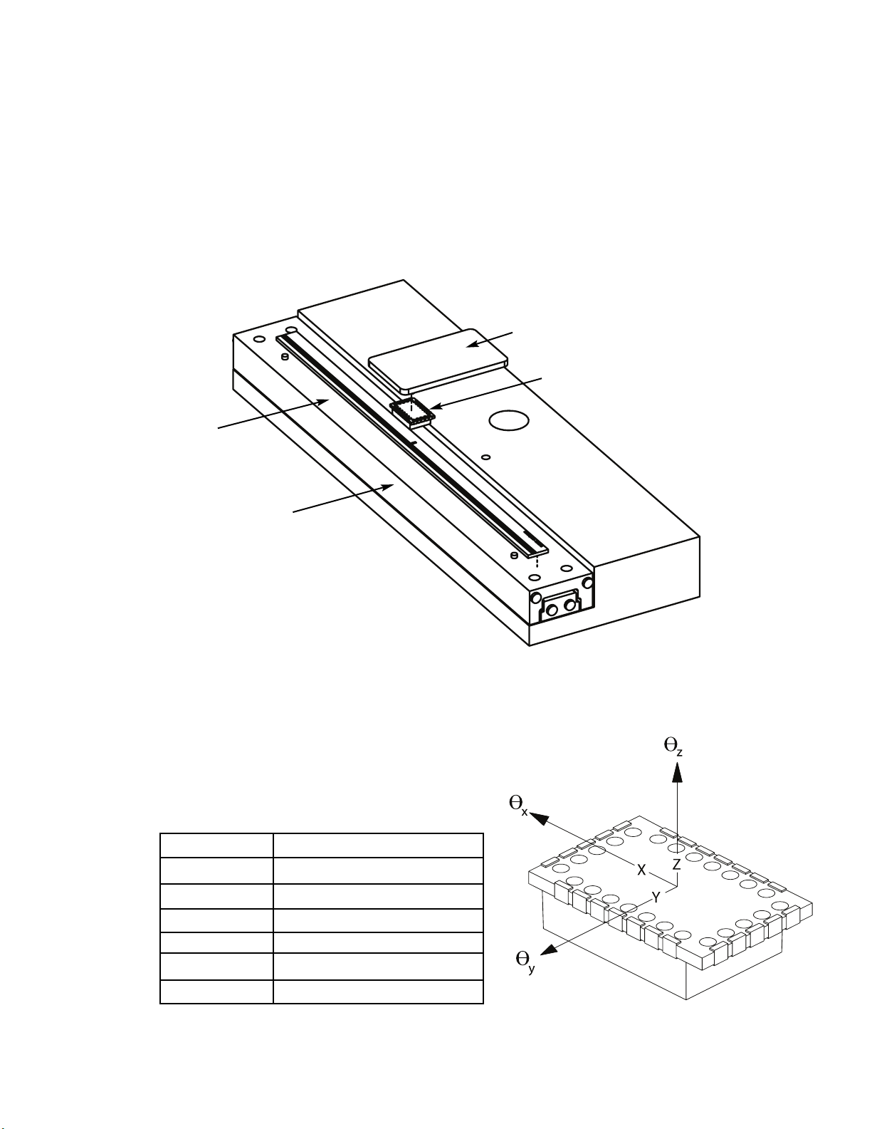
Attach the scale to the linear stage. Reference the preferred datum on the
interface drawing for either end or center index orientation.
Attach the scale to the slide with adhesive. Refer to page 6 for details
about the different methods available.
Be sure the grating surface of the scale faces the sensor. There is to be no
contact between the CE300 and the grating or damage may result.
2
The ChipEncoder CE300 should be installed on a printed circuit board (PCB) to
the electrical and mechanical specifications outlined on the interface drawings.
See page 5 for instructions on downloading interface drawings; and pages
3, 4 and 5 for information about the CE300, and CE300 to PCB assembly
instructions.
3
Page 4
If you wish to verify the encoder outputs using a digital oscilloscope to view
the A, B, and Index Window signals, please refer to page 4 for output signal
descriptions. The CE300 should not require any additional alignment as long
as the PCB and mechanical components have been fabricated and assembled
according to the mechanical dimensions and tolerances specified in the CE300
interface drawings.
ChipEncoder™ CE300
Encoder Mounting with Linear Scale
PCB
ChipEncoder
Linear Scale
Linear Stage
Axis Alignment Tolerances
x direction of motion
y ± 0.008” [0.20mm]
z ± 0.010” [0.25mm]
θ
x
± 1.5°
θ
y
± 1.5°
θ
z
± 2.0°
1
1
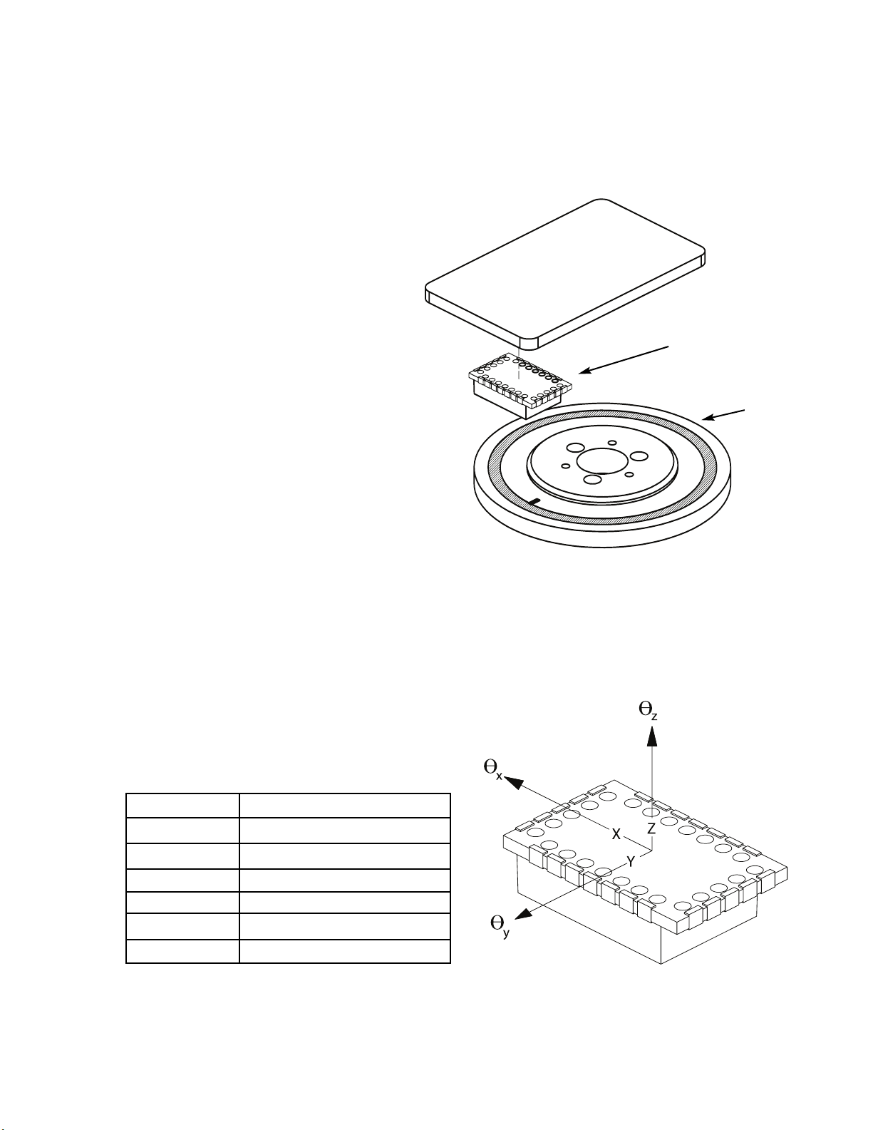
Attach your hub/scale assembly to the rotary device. Refer to the
interface drawing. The reflective surface of the scale must face
the sensor.
Be sure the grating surface of the scale faces the sensor. There is to be no
contact between the CE300 and the grating or damage may result.
2
3
Page 5
If you wish to verify the encoder outputs using a digital oscilloscope to view
the A, B, and Index Window signals, please refer to page 4 for output signal
descriptions. The CE300 should not require any additional alignment as long as
the PCB and mechanical components have been fabricated and assembled according to the mechanical dimensions and tolerances specified in the ChipEncoder interface drawings.
ChipEncoder™CE300 System
Encoder Mounting with Rotary Scale
PCB
ChipEncoder
Rotary Scale
The CE300 should be installed on a printed circuit board (PCB)
to the electrical and mechanical specifications outlined on the interface
drawings. See page 5 for instructions on downloading interface drawings;
and pages 3, 4 and 5 for information about the CE300 and, CE300 to
PCB assembly instructions.
For scales greater than 0.59” [15mm] diameter
Axis Alignment Tolerances
x direction of motion
y ± 0.006” [0.15mm]
z ± 0.010” [0.25mm]
θ
x
± 1.5°
θ
y
± 1.5°
θ
z
± 2.0°
Page 6
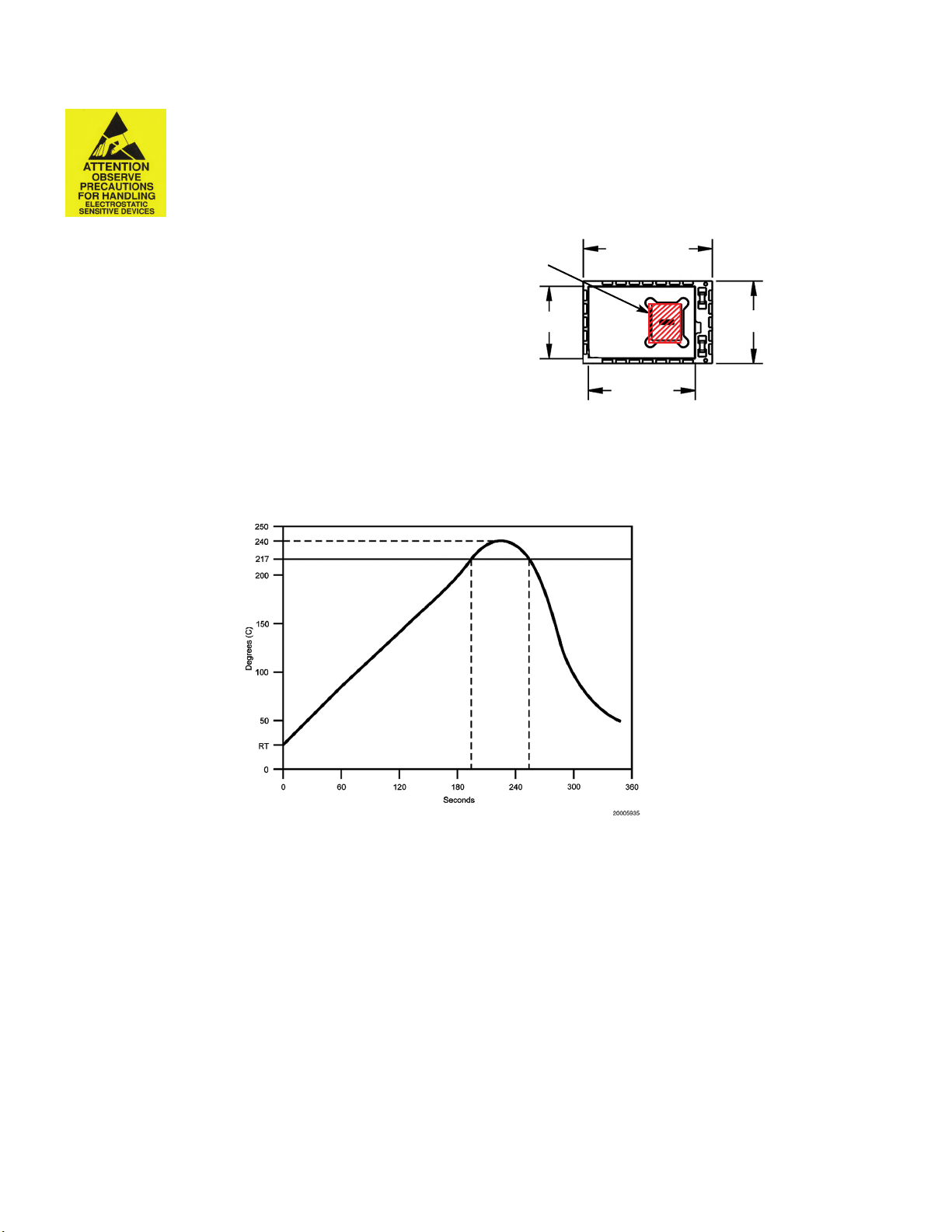
Solder Paste Recommendation and Reflow Profile
ChipEncoder™ CE300 Handling Considerations
• Note: ESD precautions should be taken at all times. Prior to reflow soldering, particular attention must be paid to preventing ESD damage as the damage
threshold is 500V.
Lead-Free Solder Reflow
The CE300 can be soldered to your PC board using industry standard solder reflow techniques. The profile above illustrates a typical temperature profile.
Use a temperature-controlled convection or IR reflow oven and SAC305 solder paste with no-clean flux in either air or an inert atmosphere (N2).
The temperature should be measured on the carrier board close to the CE300 parts and must not exceed 260°C.
CE300’s have soldered devices under the cover. Therefore, the rate of heating and cooling must be controlled so that it does not exceed 5°C
per second to avoid thermal stressing of the devices.
The CE300 inputs and outputs are pre-tinned palladium silver pads with the typical spacing between adjacent input/output pads of 0.2mm (0.008 inches).
The pads are pre-tinned with SAC305 solder alloy. Solder material with good slump characteristics should be chosen to ensure that solder does not bridge or
short during pre-heating in the reflow process.
Hand Soldering
Do not hand solder the ChipEncoder. Hand soldering will cause damage. Castellations are for electrical testing only.
KEEP OUT ZONE
.433[11.00]
.275[6.99]
.36[9.1]
.24[6.1]
• When handling the CE300 do not allow the
pick-up device to touch anywhere in the
“KEEP OUT ZONE”; refer to the illustration
below. Scratches or digs in the KEEP OUT
ZONE can affect the performance of the ChipEncoder.

Miscellaneous Application Notes
The printed circuit board (PCB) land pattern and assembly processes necessary to successfully integrate the CE300’s Ball Grid Array (BGA) package are
detailed as follows:
• IPC-SM-782 (land pattern standard) should be used as a guide for proper land pattern design for the solder pads on the printed
circuit board.
• Due to the tight spacing between solder pads, it is recommended that there be solder mask between the solder pads to prevent
solder bridging and shorting to adjacent pads.
• A stainless steel stencil, 0.003 inch [0.08 mm] thick is recommended for solder paste application to the printed
circuit board lands.
• Machine placement and reflow soldering of the CE300 is preferred. If hand soldering is necessary, soldering to the castellations
should be done noting precautions in the preceding section of this manual.
• Acetone is the recommended cleaner for the CE300.
Output Signal Descriptions
PCB Requirements
The CE300 electrical interface, land pattern, schematic of additional required passive components and mechanical dimensions are found in the CE300’s interface
drawings. See page 5 for instructions on downloading interface drawings.
Bottom view of ChipEncoder
Page 7
Pad Function Pad Function
1 Index Window+ 13 AN
2 GND 14 Sin+
3 RESERVED 15 RESERVED
4 RESERVED 16 RESERVED
5 CP+ 17 RESERVED
6 +5VA 18 GND
7 RESERVED 19 +5VD
8 GND 20 B+
9 DC2 21 B10 RESERVED 22 A+
11 DC1 23 A12 RESERVED 24 Index Window+
PAD 1
PAD 20
PAD 8
PAD 13

Page 8
Documentation Downloading Instructions
A+
B+
Index+
A+, B+ and Index Window+ output from 40X encoder
A+/A- Digital Quadrature output. Signals are RS-422 compatible square waves. Pulses are 90° out of phase with B+/B- outputs.
B+/B- Digital Quadrature output. Signals are RS-422 compatible square waves. Pulses are 90° out of phase with A+/A- outputs.
Index Window+/Index Window-
The Index Window defines one particular fringe on the grating surface. The Index Window signal is a TTL compatible
pulse, and is approximately 40 μm wide; note that this signal is not synchronized to the edge of the A or B signals.
The CE300 Data Sheet, Interface Drawings and Installation Manual are available from MicroE Systems. Contact us for these documents.
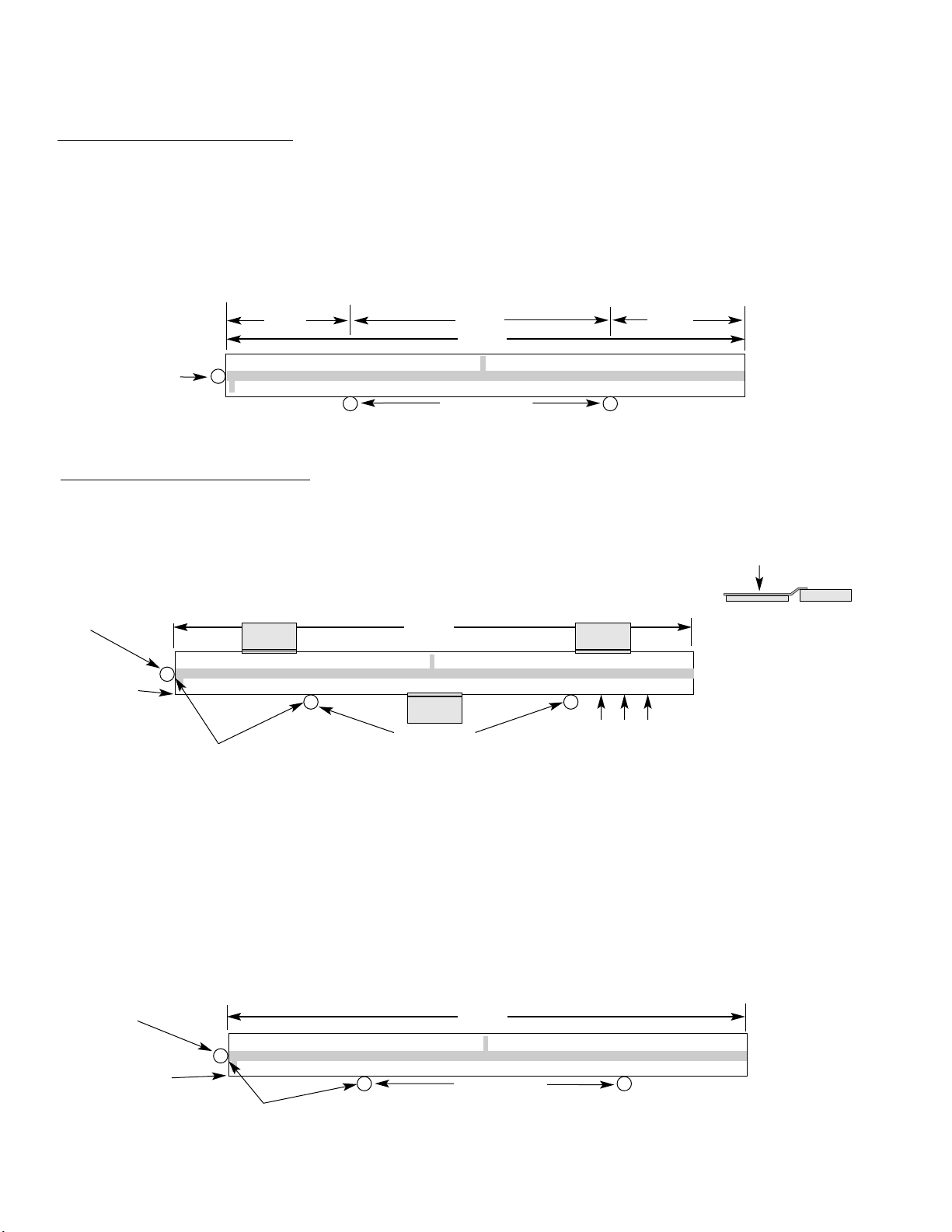
Installation of Linear Scales
MicroE Systems
L
0.2L
0.6L
0.2L
Benching pins
Positioning the Scale
Note: Before beginning mounting procedure, use talc-free gloves or finger cots to handle the scales.
"Benching" the scale to the system means aligning the scale by means of benching pins. Pin locations are described on the appropriate interface drawing.
Two benching pins are recommended on the long side of the scale and one at the end as shown . This is marked datum A on the interface drawing.
Position the benching pins in from either end. 20% of the overall scale length
is the recommended location from the edge.
Be sure the benching pins do not extend too high in the Z direction to prevent
mechanical interference with the sensor or sensor mount.
2
1
End
Benching
Pin
Mounting the Scale
MicroE Systems' linear scales should be affixed to the mounting surface. Two different approaches are described below:
RTV around entire
outside edge of scale.
End Benching
Pin
Hard epoxy
at one corner,
this end only.
Epoxy and RTV Mounting (Recommended for best accuracy)
1
Make sure the mounting surface is clean
and dry.
Optional scale clamps may be used to secure the scale while
the adhesive cures. Avoid damage to the top surface.
Side view showing optional scale clamps and scale.
Space clamps every
75mm on scales over
150 mm in length.
4
Apply a hard epoxy, such as Tra-Con’s Tra-Bond 2116, to the end of the scale at the end benching pin. Apply 100% Silicone RTV adhesive around
the edges of the scale. This method allows thermal expansion from the benched end of the scale. After adhesive curing, remove the scale mounting
clamps or, if permanently installing clamps, make sure they do not interfere with the sensor or sensor mount.
3
MicroE Systems
L
2
Align the scale by placing the edges against the benching pins.
Benching pins
Scale clamp with
adhesive
Mounting clamp
Mounting clamp
Mounting clamp
Benching pins
MicroE Systems
L
2
3
1
Two Sided Adhesive Tape Mounting
Make sure the mounting surface is clean and dry. Peel the
cover paper off and place the scale above the final location.
Align the scale by placing the edges against the benching pins.
Gently place the scale on the mounting surface. Positioning adjustments can be made until the
scale is firmly pressed down. After final positioning, push down on the top of the scale to
secure it.
End Benching
Pin
Hard epoxy at one
corner,
this end only.
Page 9

Page 10
Contacting MicroE Systems
Cleaning Scales
General Particle Removal
Blow off the contamination with nitrogen, clean air, or a similar gas.
Thank you for purchasing a MicroE Systems product. You should expect the highest level of quality and
support. If you have any questions please call MicroE Systems for support or to obtain the ChipEncoder
™
User Manual, Data Sheet or Interface Drawings.
Contamination Removal
Use a lint-free cleanroom wipe or cotton swab dampened with isopropyl alcohol
or acetone only to wipe the surface clean. Handle the scale by the edges.
Do not scrub the scale.
World Headquarters: 125 Middlesex Turnpike • Bedford • MA 01730
www.microesy.com • info@microesys.com • T. [781] 266-5700 • F. [781] 266-5112
Copyright © 2011 MicroE Systems
 Loading...