

Page 1

EPS 6000 UPS
Shared Systems
User’s Guide
Page 2
IMPORTANT SAFETY INSTRUCTION
SA VE THESE INSTRUCTIONS — This manual contains important instructions for the EPS
6000 series UPS Systems that must be followed during installation, operation and
maintenance of the equipment.
WARNING
OPENING ENCLOSURES EXPOSES HAZARDOUS
VOLTAGES. ALWAYS REFER SERVICE TO
QUALIFIED PERSONEL ONLY
WARNING
As standards, specifications, and designs are
subject to change, please ask for confirmation of
the information given in tihs publicaion.
This manual is a controlled document, pages
should not individually be removed from this
binder.
NOTE
This equipment generates, uses, and can radiate
radio frequency energy and, if not installed and
used in accordance with instruction manual, may
cause harmful interference to radio
communications. Operation of this equipment in a
residential area is likely to cause harmful
interference in which case the user will be required
to correct the interference at his own expense.
Page 3

For service call
1-800-438-7373
86-130034-00 B00 11/96
Copyright © 1996 MGE UPS Systems, Inc..
All rights reserved. Printed in U.S.A.
MGE UPS Systems
1660 Scenic Avenue
Costa Mesa, CA 92626
(714) 557-1636
prepared for:
EPS 6000
Shared Systems
User’s Guide
Page 4

Warranty
Seller warrants to the Ultimate Purchaser (the purchaser who buys for use, and not for resale) that all products
furnished under this order and which are manufactured by Seller will conform to final specifications, drawings, samples
and other written descriptions approved in writing by Seller, and will be free from defects in materials and workmanship.
These warranties shall remain in effect for period of twelve (12) months after delivery to the Ultimate Purchaser. But if the
Seller installs the equipment or supplies technical direction of installation by contract, said one year shall run from the
completion of installation, provided installation is not unreasonably delayed by Ultimate Purchaser.Parts replaced or
repaired in the warrant period shall carry the unexpired portion of the original warranty.A unit placed with the Purchaser
on consignment and then later purchased will be warranted for twelve (12) months from the time the Seller receives notification of the Purchaser’s intent to purchase said consigned item.The foregoing in its entirety is subject to the provision
that in no case will the total warranty period extend beyond 18 months from date Seller ships equipment from point of
manufacture.
The liability of Seller hereunder is limited to replacing or repairing at Seller’s factory or on the job site at Seller’s
option, any part or parts which have been returned to the Seller and which are defective or do not conform to such specifications, drawings or other written descriptions; provided that such part or parts are returned by the Ultimate Purchaser
within ninety (90) days after such defect is discovered. The Seller shall have the sole right to determine if the parts are to
be repaired at the job site or whether they are to be returned to the factory for repair or replacement. All items returned to
Seller for repair or replacement must be sent freight prepaid to its factory. Purchaser must obtain Seller’s Return Goods
Authorization prior to returning items.The above conditions must be met if warranty is to be valid. Seller will not be liable
for any damage done by unauthorized repair work, unauthorized replacement parts, from any misapplication of the item,
or for damage due to accident, abuse, or Act of God.
In no event shall the Seller be liable for loss, damage, or expense directly or indirectly arising from the use of the
units, or from any other cause, except as expressly stated in this warranty. Seller makes no warranties, express or
implied, including any warranty as to merchantability or fitness for a particular purpose or use. Seller is not liable for and
Purchaser waives any right of action it has or may have against Seller for any consequential or special damages arising
out of any breach of warranty, and for any damages Purchaser may claim for damage to any property or injury or death to
any person arising out of its purchase of the use, operation or maintenance of the product. Seller will not be liable for any
labor subcontracted or performed by Purchaser for preparation of warranted item for return to Seller’s factory or for
preparation work for field repair or replacement.Invoicing of Seller for labor either performed or subcontracted by
Purchaser will not be considered as a liability by the Seller.
This warranty shall be exclusive of any and all other warranties express or implied and may be modified only by a
writing signed by an officer of the Seller.This warranty shall extend to the Ultimate Purchaser but to no one else.
Accessories supplied by Seller, but manufactured by others, carry any warranty the manufacturers have made to Seller
and which can be passed on to Ultimate Purchaser.
Seller makes no warranty with respect to whether the products sold hereunder infringe any patent, U.S. or foreign,
and Buyer represents that any specially ordered products do not infringe any patent.Buyer agrees to indemnify and hold
Seller harmless from any liability by virtue of any patent claims where Buyer has ordered a product conforming to Buyer’s
specifications, or conforming to Buyer’s specific design.
Buyer has not relied and shall not rely on any oral representation regarding the Product sold hereunder and any oral
representation shall not bind Seller and shall not be part of any warranty.
There are no warranties which extend beyond the description on the face hereof. In no event shall MGE UPS
Systems, Inc. be responsible for consequential damages or for any damages except as expressly stated herein.
Service and Factory Repair - Call 1 - 800 - 438 - 7373
Direct questions about the operation, repair, or servicing of this equipment to MGE UPS Systems, Inc.Customer
Support Services. Include the par t number, assembly number, and serial number of the unit in any correspondence.
Should you require factory service for your equipment, contact MGE UPS Systems, Inc.Customer Suppor t Ser vices and
obtain a Return Goods Authorization (RGA) prior to shipping your unit. Never ship equipment to MGE UPS Systems, Inc.
without first obtaining an RGA.
Proprietary Rights Statement
The information in this manual is the property of MGE UPS Systems, Inc., and represents a proprietary article in
which MGE UPS Systems, Inc., retains any and all patent rights, including exclusive rights of use and/or manufacture
and/or sale. Possession of this information does not convey any permission to reproduce, print, or manufacture the article
or articles shown herein. Such permission may be granted only by specific written authorization, signed by an officer of
MGE UPS Systems, Inc.
IBM, PC-AT, ES/9000, and AS/400 are trademarks of International Business Machines Corporation. MGE and MGE
UPS Systems are trademarks of MGE UPS Systems, Inc. Other trademarks that may be used herein are owned by their
respective companies and are referred to in an editorial fashion only.
Revision History
EPS 6000 Uninterruptible Power System Installation Manual
86-130034-00
Copyright © 1996 MGE UPS Systems. All rights reserved. Printed in U.S.A.
Revision: B00 11/96
EPS 6000 UPS
Shared Systems
User’s Guide
Page 5

Section I Introduction
1.0 . . . . . . . . . . . . . . . Scope 1 — 1
1.1 . . . . . . . . . . . . . . . General Description 1 — 1
1.2 . . . . . . . . . . . . . . . Description of UPS Module
Major Internal Components 1 — 4
1.2.1 Rectifier/Battery Charger 1 — 4
1.2.2 Inverter 1 — 4
1.2.3 Inverter Transformer 1 — 4
1.2.4 Battery System 1 — 4
1.3 . . . . . . . . . . . . . . . Description of SSC
Major Internal Components 1 — 5
1.4 . . . . . . . . . . . . . . . Options 1 — 13
1.5 . . . . . . . . . . . . . . . Specifications, UPS Modules 1 — 13
1.5.1 Electrical 1 — 13
1.5.2 Mechanical 1 — 14
1.5.3 Environmental 1 — 15
1.6 . . . . . . . . . . . . . . . Specifications,
Static Switch Cabinet 1 — 15
1.6.1 Electrical 1 — 15
1.6.2 Mechanical 1 — 16
1.6.2 Mechanical 1 — 12
Section II Operation
2.0 . . . . . . . . . . . . . . . Scope 2 — 1
2.1 . . . . . . . . . . . . . . . System Operation Overview 2 — 1
2.1.1 Static Switch Cabinet Operation 2 — 1
2.1.2 Normal Operation 2 — 2
2.1.3 On-Battery Operation 2 — 2
2.2 . . . . . . . . . . . . . . . Indicators and Controls 2 — 3
2.2.1 Front Panel 2 — 3
2.2.2 Alphanumeric Display
and Controls 2 — 6
2.2.3 Hidden Panel 2 — 9
2.2.4 Circuit Breakers,
Contactors and Switches 2 — 13
2.3 . . . . . . . . . . . . . . . Using the Alphanumeric Display 2 — 23
2.3.1 Settings 2 — 24
2.3.2 Alarms 2 — 25
2.3.3 Measurements 2 — 26
2.3.3.1 Voltage Measurements 2 — 26
2.3.3.2 Current Measurements 2 — 27
2.3.3.3 Power and
Frequency Measurements 2 — 28
2.3.3.4 Battery Measurements 2 — 29
iii
Contents
Page 6

section description page number
2.4 . . . . . . . . . . . . . . . Normal Operating Procedures 2 — 29
2.4.1 Checks Before Start-up 2 — 29
2.4.2 Start-up 2 — 30
2.4.3 Checks After Start-up 2 — 31
2.4.4 Shut-down 2 — 32
2.4.4.1 Emergency Shutdown
Using EPO 2 — 32
2.4.4.2 Normal Shutdown 2 — 33
2.4.5 Isolation for Maintenance 2 — 33
2.4.5.1 Isolation of an
Individual UPS Module 2 — 33
2.4.5.2 Isolation of
Static Switch Cabinet (SSC) 2 — 35
2.4.5.2.1 Without Maintenance Bypass 2 — 35
2.4.5.2.2 With Maintenance Bypass 2 — 35
2.4.6 Forced Transfers 2 — 36
2.4.6.1 Uninterrupted
Transfer Conditions 2 — 36
2.4.6.2 Forced Transfer From
Bypass AC Input Source
to Inverter 2 — 37
2.4.6.3 Forced UPS Module Shut Down 2 — 37
2.5 . . . . . . . . . . . . . . . LCD Messages 2 — 37
Section III Maintenance and Service
3.0 . . . . . . . . . . . . . . . Scope 3 — 1
3.1 . . . . . . . . . . . . . . . Safety Instructions 3 — 1
3.2 . . . . . . . . . . . . . . . Preventive Maintenance 3 — 1
3.3 . . . . . . . . . . . . . . . Replacement Parts 3 — 2
3.4 . . . . . . . . . . . . . . . Troubleshooting and
MGE Servicing 3 — 3
Glossary
. . . . . . . . . . . . . . . . . . . . . . . . . . . . . . . . . . . . . . . . . . g — 1
iv Contents
EPS 6000 UPS Shared Systems
Page 7

Illustrations
figure description page number
1-1 . . . . . . . . . . . . . . . Pictorial, Typical EPS 6000 UPS
Shared Installation
(Shown With Two 375 kVA
UPS Modules) 1 — 3
1-2 . . . . . . . . . . . . . . . Single-Line Diagram,
Typical EPS 6000 UPS
Shared Installation 1 — 3
1-3 . . . . . . . . . . . . . . . EPS 6000
Major Internal Components,
Shared 150 - 225 kVA
UPS Modules 1 — 5
1-4 . . . . . . . . . . . . . . . EPS 6000
Major Internal Components,
Shared 375 kVA UPS Modules 1 — 6
1-5 . . . . . . . . . . . . . . . EPS 6000
Major Internal Components,
Shared 500 kVA UPS
I/O Cabinet 1 — 7
1-6 . . . . . . . . . . . . . . . EPS 6000
Major Internal Components,
Shared 500 kVA UPS Cabinet 1 — 8
1-7 . . . . . . . . . . . . . . . EPS 6000
Major Internal Components,
Shared 750 kVA UPS Cabinet 1 1 — 9
1-8 . . . . . . . . . . . . . . . EPS 6000
Major Internal Components,
Shared 750 kVA UPS Cabinet 2 1 — 10
1-9 . . . . . . . . . . . . . . . EPS 6000
Major Internal Components,
Shared 750 kVA UPS
Cabinet 3 1 — 11
1-10 . . . . . . . . . . . . . . EPS 6000
Major Internal Components,
Static Switch Cabinet (SSC) 1 — 12
2-1 . . . . . . . . . . . . . . . Power Flow, Normal Operation 2 — 1
2-2 . . . . . . . . . . . . . . . Power Flow,
On-Battery Operation 2 — 2
2-3 . . . . . . . . . . . . . . . Power Flow, Bypass Operation 2 — 3
2-4 . . . . . . . . . . . . . . . EPS 6000
Controls and Indicators 2 — 4
2-5 . . . . . . . . . . . . . . . EPS 6000 Front Panel 2 — 4
2-6 . . . . . . . . . . . . . . . Alphanumeric Display
and Controls 2 — 7
2-7 . . . . . . . . . . . . . . . Hidden Panel 2 — 9
2-8 . . . . . . . . . . . . . . . Hidden Panel Pushbuttons 2 — 12
vContents
User’s guide
Page 8

2-9 . . . . . . . . . . . . . . . Single-Line Diagram,
Typical EPS 6000 UPS
Shared Installation 2 — 14
2-10 . . . . . . . . . . . . . . EPS 6000
Major Internal Components,
Shared 150 - 225 kVA
UPS Module 2 — 15
2-11 . . . . . . . . . . . . . . EPS 6000
Major Internal Components,
Shared 300 / 375 kVA
UPS Module 2 — 16
2-12 . . . . . . . . . . . . . . EPS 6000
Major Internal Components,
Shared 500 kVA UPS Module
I/O Cabinet 2 — 17
2-13 . . . . . . . . . . . . . . EPS 6000
Major Internal Components,
Shared 500 kVA UPS Module
UPS Cabinet 2 — 18
2-14 . . . . . . . . . . . . . . EPS 6000
Major Internal Components,
Shared 750 kVA UPS Module
UPS Cabinet 1 2 — 19
2-15 . . . . . . . . . . . . . . EPS 6000
Major Internal Components,
Shared 750 kVA UPS Module
UPS Cabinet 2 2 — 20
2-16 . . . . . . . . . . . . . . EPS 6000
Major Internal Components,
Shared 750 kVA UPS Module
UPS Cabinet 3 2 — 21
2-17 . . . . . . . . . . . . . . EPS 6000
Major Internal Components,
Static Switch Cabinet (SSC) 2 — 22
2-18 . . . . . . . . . . . . . . Alphanumeric Display 2 — 23
2-19 . . . . . . . . . . . . . . General Display Configuration 2 — 24
2-20 . . . . . . . . . . . . . . Display Settings Display 2 — 24
2-21 . . . . . . . . . . . . . . Displaying Alarm Messages 2 — 25
2-22 . . . . . . . . . . . . . . Voltage Measurements 2 — 26
2-23 . . . . . . . . . . . . . . Current Measurements 2 — 27
2-24 . . . . . . . . . . . . . . Power and
Frequency Measurements 2 — 28
2-25 . . . . . . . . . . . . . . Battery Measurements 2 — 29
vi Contents
EPS 6000 UPS Shared Systems
Page 9

Tables
table description page number
1-1 . . . . . . . . . . . . . . . EPS 6000 Model Numbers,
Shared System UPS Modules 1 — 2
1-2 . . . . . . . . . . . . . . . EPS 6000 Model Numbers,
Static Switch Cabinets (SSC) 1 — 2
viiContents
User’s guide
Page 10
This manual is designed for ease of use and easy location
of information.
To quickly find the meaning of terms used within the text, look in the Glossary.
This manual uses Noteboxes to convey important information. Noteboxes come in four
varieties:
How to use this manual
viii
EPS 6000 UPS Shared Systems
WARNING
A WARNING notebox
indicates information
provided to protect the
user and service
personnel against safety
hazards and/or possible
equipment damage
IMPORTANT
CAUTION
A CAUTION notebox
indicates information
provided to protect the
user and service
personnel against
possible equipment
damage.
NOTE
An IMPORTANT notebox
indicates information
provided as an operating
instruction, or as an
operating tip.
A NOTE notebox
indicates information
provided as an
operating tip or an
equipment feature.
Page 11

This manual provides technical information required for
operation and maintenance of the shared EPS 6000
uninterruptible power system (UPS). Please read this manual before operating the EPS 6000
equipment. Please retain this manual for future reference.
The manual is divided into three sections:
Section I — General Description
This section introduces the EPS 6000 family of uninterruptible power systems, including a
general description of the system and its internal components, a description of available
options, and system specifications.
Section II — Operation
This section describes operating information for EPS 6000 UPS shared systems, including
an overview of the system, its components, and their function;a description of the
indicators and controls and their function; and operational sequences to be followed for all
conditions of normal, emergency, and maintenance operation.
Section III — Maintenance and Service
This section describes maintenance of the EPS 6000 UPS, including safety instructions,
preventive maintenance, information about replacement parts, and customer service.
A Glossary in the rear of this manual provides definitions of terms used within the text. A
separate manual, EPS 6000 UPS Installation Manual (MGE part number 86-130035-00)
provides detailed installation instructions.
EPS 6000 is a family of compact, high-efficiency uninter-
ruptible power systems, available in power ratings up to
1,500 kVA. EPS 6000 UPS are optimized for compatibility with non-linear computer-type
loads. Computer-aided UPS diagnostics and modular construction assures that any required
service on the UPS can be identified and completed rapidly. Remote system monitoring,
remote annunciation of UPS performance signals, and telecommunication capabilities allow
total control of the UPS by the user.
The EPS 6000 UPS, SSC, battery, and all auxiliar y equipment is listed for safety by
Underwriter’s Laboratories, Inc.(UL) under UL Standard 1778; and under
Canadian Standards Association (CSA) standard C22.107.
Major components of the EPS 6000 UPS family include:
• EPS 6000 UPS module
• EPS 6000 SSC static switch cabinet
• EPS 6000 SSC maintenance bypass cabinet
• EPS 6000 auxiliary cabinet
1.1 General Description
1.0 Scope
1 — 1
Introduction
Page 12

• EPS 6000 battery cabinet
Each of these cabinets is described below. Figure 1-1 shows a typical shared UPS
installation, consisting of one static switch cabinet (SSC), two UPS modules, and two adjacent
battery cabinets. Figure 1-2 shows a single-line diagram of the same
shared UPS installation. Table 1-1 identifies EPS 6000 UPS model numbers for modules
used in shared systems, and Table 1-2 identifies EPS 6000 SSC model numbers.
Table EPS 6000 Model Numbers, Shared System UPS Modules
1-1
Table
EPS 6000 Model Numbers, Static Switch Cabinets (SSC)
1-2
1 — 2 Introduction
EPS 6000 UPS Shared Systems
LEDOM
REBMUN
P66,44/0516-SPE084084021/0510045.18/010,2805,4/440,2818,03
P66,44/5226-SPE084084081/5220045.18/010,2805,4/440,2202,93
-SPEP66,44/0036084084042/0030065.18/010,2345,5/415,2962,25
P66,44/5736-SPE084084003/5730075.18/010,2216,5/545,2633,56
P66,44/0056-SPE084084004/0050001311/568,2112,7/442,4354,97
6-SPEP66,44/057084084006/0570061591/009,42,31/000,600,131000
:SETON
.1 .stellapgnidulcxetubstenibacyrailixuagnidulcnipu-enilmetsysroferassoltaehdna,thgiew,htdiwlatoT
.2 .tnempiuqeruoyhtiwdeilppussgniwardnoitallatsniehtotrefer;atadyrettabedulcnitonseodataD
.3 ehttlusnoC.tnempiuqelanoitpohtiwegnahcyamatad;snoitarugifnocdradnatsrofsidedivorpnoitamrofnI
LEDOM
REBMUN
0051CSS0840840021/0051000227/92810092/7131)elbigilgeN(
TUPNI
EGATLOV
)CAV(
TUPNI
EGATLOV
)CAV(
TUPTUO
EGATLOV
)CAV(
TUPTUO
EGATLOV
)CAV(
TUPTUO
GNITAR
)Wk/AVk(
.tnempiuqeruoyhtiwdedivorpsgniwardnoitallatsni
TUPTUO
GNITAR
Wk/AVk
BCTUPNI
)spmA(
BCTUPNI
)serepmA(
HTDIWLATOT
)ni/mm(
LATOT
HTDIW
)ni/mm(
LATOT
THGIEW )bl/gk(
LATOT
THGIEW
)bl/gk(
TAEH
SSOL
)rh/utB(
TAEH
SSOL
)rh/utB(
Page 13
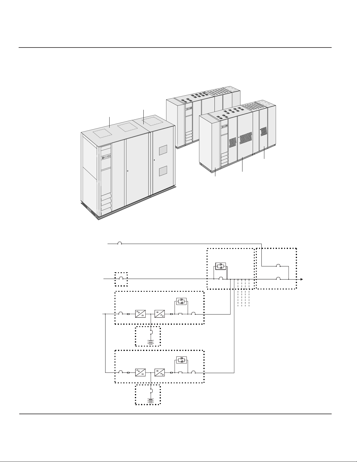
Figure Pictorial, Typical EPS 6000 UPS Shared Installation
1-1 (Shown With Two 375 kVA UPS Modules)
Figure Single-Line Diagram, Typical EPS 6000 UPS Shared Installation
1-2
1 — 3Introduction
User’s guide
MAINTENANCE
BYPASS
CABINET
STATIC SWITCH
(OPTIONAL)
CABINET (SSC)
BATTERY
CABINET
STATIC SWITCH
Q2S
EPS 6000
UPS MODULE
CABINET
MAINTENANCE
BYPASS CABINET
(OPTIONAL)
Q38P
Q5N
TO
ATTACHED
LOAD
AUXILIARY
CABINET
MAINTENANCE
BYPASS
AC INPUT/
MAINS 2
BYPASS
AC INPUT
Q4S
(CUSTOMER
SUPPLIED)
STATIC SWITCH
MAIN
AC INPUT/
MAINS 1
EPS 6000 UPS MODULE
Q1
INPUT
FUSES
RECTIFIER/
CHARGER
EPS 6000 UPS MODULE
Q1
INPUT
FUSES
RECTIFIER/
CHARGER
EPS 6000
BATTERY
CABINET
EPS 6000
BATTERY
CABINET
INVERTER
QF1
INVERTER
QF1
OUTPUT
FUSES
OUTPUT
FUSES
STATIC SWITCH
K3N
STATIC SWITCH
K3N
Q5N
Q5N
FROM ADDITIONAL
UPS MODULES
Page 14

Following is a description of the EPS 6000 UPS major
internal components. Refer to the single-line diagram
provided in Figure 1-2, and the component locators
provided in Figure 1-3 through Figure 1-10
The rectifier/battery charger converts the AC input voltage
from the utility source into a DC voltage, supplying the
inverter and regulating the charge of the battery system. A
capacitor bank filters the DC voltage.
The inverter chops the DC voltage supplied from either the
rectifier/battery charger or the battery system into a threephase AC voltage. An AC output filter is used to achieve a computer-grade sinewave output
voltage waveform, with a total harmonic distortion of less than 2% under linear-load conditions.
During normal operation, the inverter transformer provides
complete electrical isolation between the UPS output to the
attached load and the utility power source input as well as
the UPS battery source.
The battery system stores energy for use by the inverter.
The stored energy is utilized in the event that the AC input
power from the utility source fails, or falls outside of acceptable tolerance.
The battery system may be an MGE battery cabinet designed for operation with the EPS 6000
UPS, or a customer-supplied battery installation.
MGE-supplied EPS 6000 battery cabinets may be a provided as stand-alone enclosures, or as
enclosures designed to be mounted adjacent to the EPS 6000 UPS module.
The EPS 6000 comes with a special battery ambient temperature sensor which allows the
optimization of the DC voltage level as a function of the temperature, ensuring that the battery
is properly charged and preserving its longevity.
1.2.4 Battery System
1.2.3 Inverter
Transformer
1.2.2 Inverter
1.2.1 Rectifier/Battery
Charger
1.2 Description of UPS
Module Major
Internal
Components
1 — 4 Introduction
EPS 6000 UPS Shared Systems
Page 15
The static switch cabinet (SSC) provides an electrical path
between the output of the UPS modules and the load.
When the UPS modules are off, the SSC provides power to
the load from the bypass AC input source (mains 2). Up to
six (6) modules can be connected to the SSC, supporting
loads as great as 1,500 kVA. UPS modules may be turned
off individually for maintenance, provided that the remaining modules can support the load.
The SSC incorporates a static bypass switch. A wrap-around circuit breaker (Q2S) in the SSC
switches between the UPS module output and the bypass AC input source (when the UPS
modules are off). Optionally, the SSC can be provided with its own maintenance bypass
cabinet (MBC), allowing the SSC and/or any attached UPS module to be serviced while the
load is supplied via the maintenance bypass AC input source.
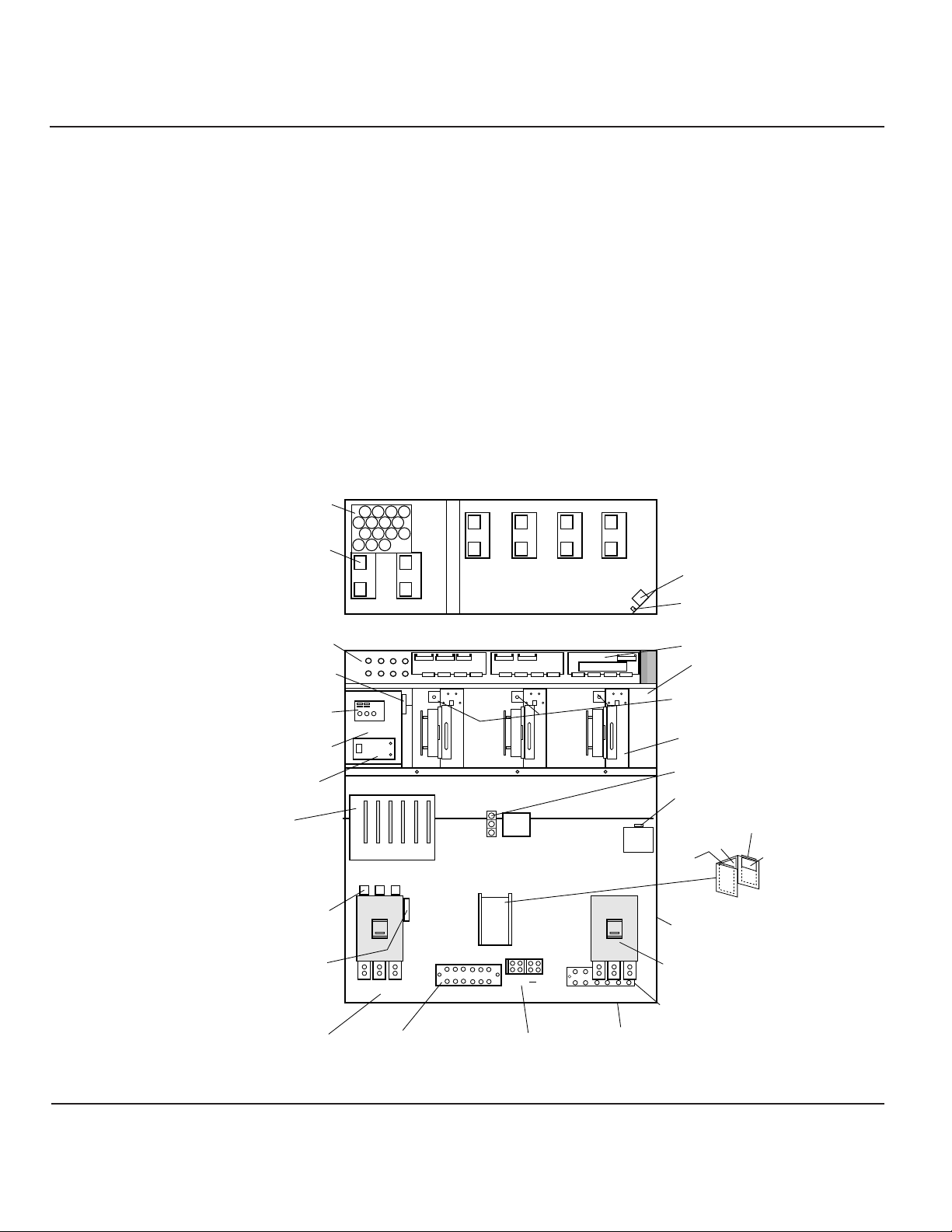
Figure EPS 6000 Major Internal Components,
1-3 Shared 150 - 225 kVA UPS Modules
1.3 Description of SSC
Major Internal
Components
1 — 5Introduction
User’s guide
AC CAPACITOR
ASSEMBLY
FANS
(x 6)
FB1 TO FB8
F10,F11 RATED 2A,500VDC
CHARGER, STATIC SW,
(BEHIND PLATE)
CARD CAGE:
1- GTCZ PCA
2- SRIZ PCA
3- CRIZ PCA
4- CROZ / DO6Z PCA
5- AROZ PCA
6- ALEZ PCA
INPUT FUSES F1, F2, F3
F12,F13
EPOZ
BAIZ & TREZ
ALBZ
1 2
TOP VIEW, COVER REMOVED
FRONT VIEW, DOORS AND COVERS REMOVED
FB4
FB2FB1
FB3
RAUZ PCA
FB8
FB6FB5
FB7
OBEZ PCA
K3N
23456
1
Q1 Q5N
6543
FAN
TRANSFORMER
FB9
IBEZ PCA
DC CAPACITORS
(BEHIND EACH INVERTER)
INVERTER FUSES (BEHIND)
INVERTERS
OUTPUT FUSES F7, F8, F9
120V AC OUTLET
(FOR MGE USE ONLY)
ARUZ PCA (BEHIND MTG. PLATE)
ACPZ PCA
APOZ PCA
OUTPUT XFMR
(BEHIND BREAKERS)
K3NZ PCA
FUSES F16, F17
F18, F19
INPUT
CONNECTIONS
C3B3A3
GROUND
CONNECTIONS
+
BATTERY
CONNECTIONS
C4B4A4
OUTPUT
CONNECTIONS
OUTPUT
CIRCUIT BREAKER
NEUTRAL CONNECTION
(BEHIND OUTPUT)
Page 16
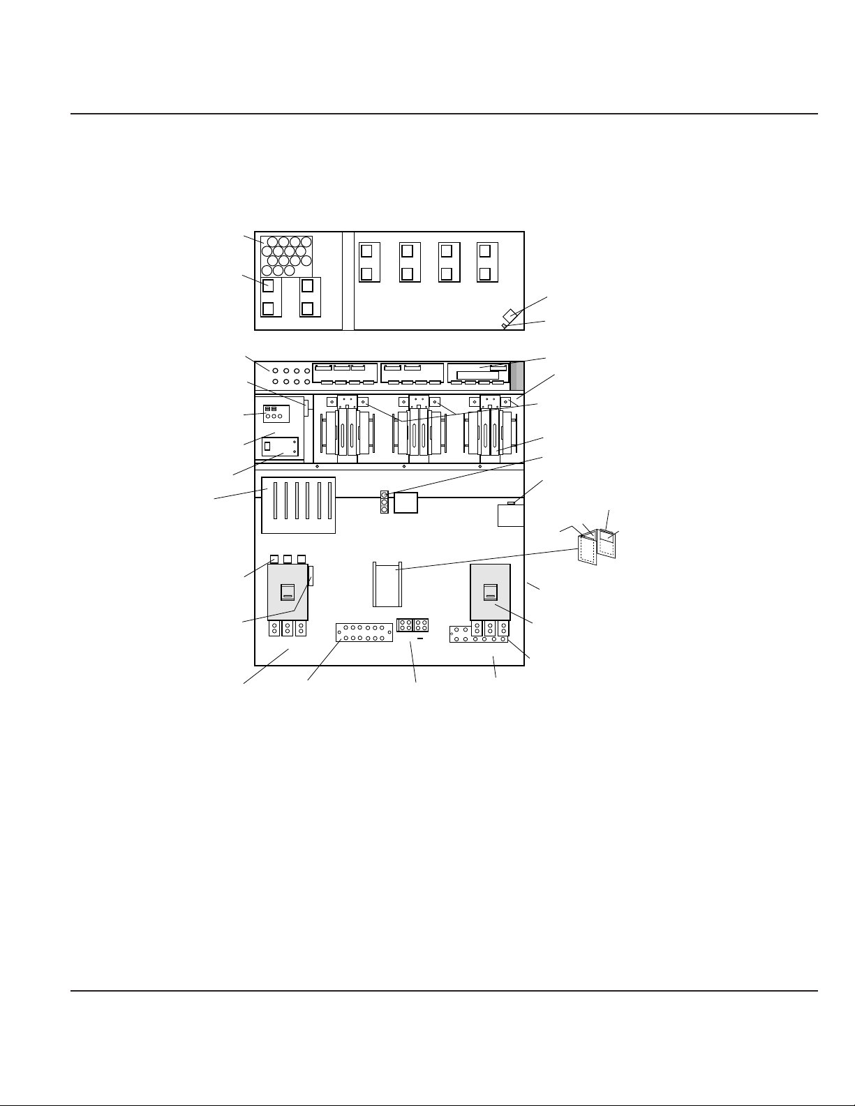
Figure EPS 6000 Major Internal Components,
1-4 Shared 375 kVA UPS Modules
1 — 6 Introduction
EPS 6000 UPS Shared Systems
AC CAPACITOR
ASSEMBLY
FANS
(x 6)
FB1 TO FB8
F10,F11 RATED 2A,500VDC
CHARGER, STATIC SW,
(BEHIND PLATE)
CARD CAGE:
1- GTCZ PCA
2- SRIZ PCA
3- CRIZ PCA
4- CROZ / DO6Z PCA
5- AROZ PCA
6- ALEZ PCA
INPUT FUSES F1, F2, F3
F12,F13
EPOZ
BAIZ & TREZ
ALBZ
1 2
TOP VIEW, COVER REMOVED
FRONT VIEW, DOORS AND COVERS REMOVED
FB4
FB2FB1
FB3
RAUZ PCA
FB8
FB6FB5
FB7
21
OBEZ PCA
K3N
23456
1
Q1 Q5N
543
43
FAN
TRANSFORMER
FB9
IBEZ PCA
DC CAPACITORS
(BEHIND EACH INVERTER)
INVERTER FUSES (BEHIND)
665
F23 TO F34
INVERTERS (x6)
OUTPUT FUSES F7, F8, F9
120V AC OUTLET
(FOR MGE USE ONLY)
ARUZ PCA (BEHIND MTG. PLATE)
ACPZ PCA
APOZ PCA
OUTPUT XFMR
(BEHIND BREAKERS)
K3NZ PCA
FUSES F16, F17
F18, F19
INPUT
CONNECTIONS
C3B3A3
GROUND
CONNECTIONS
+
BATTERY
CONNECTIONS
C4B4A4
OUTPUT
CONNECTIONS
OUTPUT
CIRCUIT BREAKER
NEUTRAL CONNECTION
(BEHIND OUTPUT)
Page 17
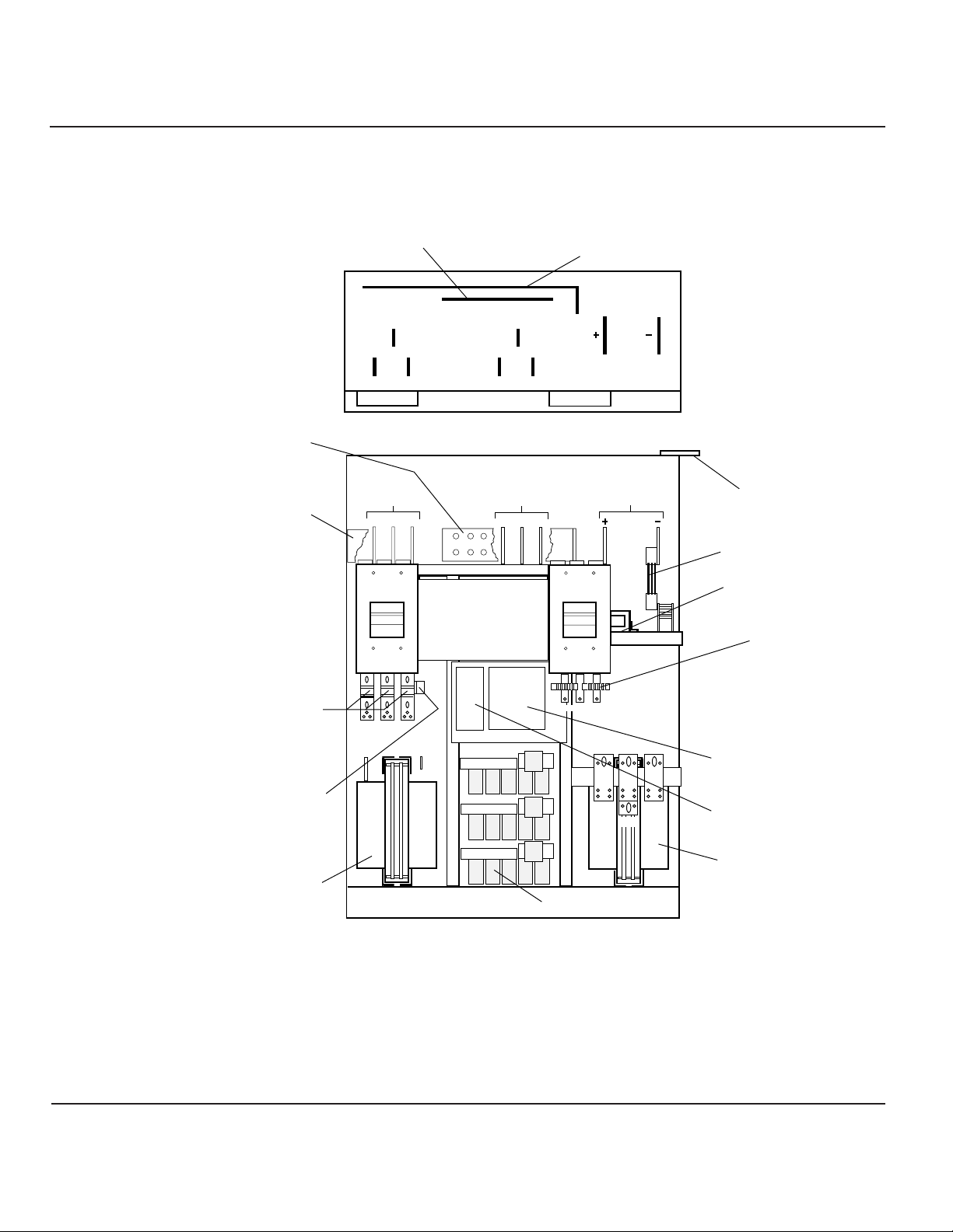
Figure EPS 6000 Major Internal Components,
1-5 Shared 500 kVA UPS I/O Cabinet
1 — 7Introduction
User’s guide
CONNECTION
CONNECTION
NEUTRAL CONNECTION
NEUTRAL
GROUND
TOP VIEW, COVERS REMOVED
FRONT VIEW, DOORS AND COVERS REMOVED
INPUT
CONNECTIONS
A3 B3 C3
Q1
OUTPUT
CONNECTIONS
A4 B4 C4
GROUND CONNECTION
BATTERY
CONNECTIONS
Q5N
BONDING
JUMPER
SHUNT
L2
CURRENT XFMRS
INPUT FUSES
F1,F2,F3
FUSES F16,F17
L3
A12B12 C12
C1B1A1
N12
ACPZ
A2
C2
B2
ARUZ
L4
AC CAPACITORS
Page 18
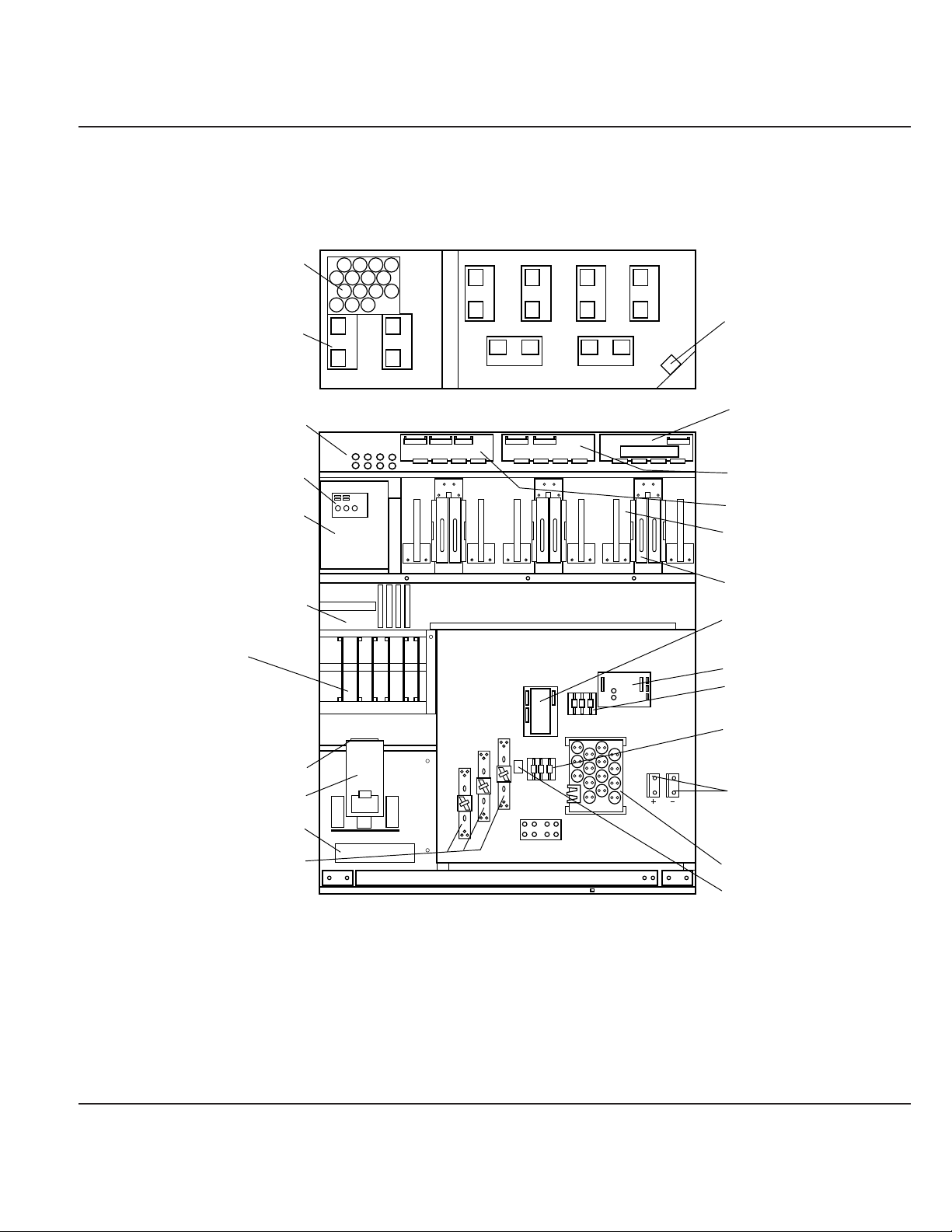
Figure EPS 6000 Major Internal Components,
1-6 Shared 500 kVA UPS Cabinet
)
1 — 8 Introduction
EPS 6000 UPS Shared Systems
AC CAPACITOR
ASSEMBLY
543
FB1 TO FB8
CHARGER & TREZ
(BEHIND PLATE)
AC OUTPUT
CAPACITORS
CARD CAGE:
1- GTCZ PCA
2- SRIZ PCA
3- CRIZ PCA
4- CROZ / DO6Z PCA
5- AROZ PCA
6- ALEZ PCA
STATIC SWITCH
OUTPUT FUSES
F7, F8, F9
FANS
(x 8)
EPOZ
K3NZ
K3N
1 2
FRONT VIEW, DOORS AND COVERS REMOVED
123456
7 8
TOP VIEW, COVER REMOVED
4321
NEUTRAL
FAN
TRANSFORMER
IBEZ
OBEZ
665
RAUZ
DC CAPACITERS
(BEHIND EACH INVERTER
INVERTERS (x6)
APOZ
ALBZ
F10,F11,F18,F19
F12,F13
DELAY
BATTERY
CONNECTION
(OPTIONAL)
AC CAP ASSY.
K1
Page 19

Figure EPS 6000 Major Internal Components,
1-7 Shared 750 kVA UPS Cabinet 1
C
1 — 9Introduction
User’s guide
Resistors
apacitors
Ground
onnection
Input fuses
F1, F2, F3
Input Filter
Capacitors
Neutral
Connection
Input
Connections
A3 B3 C3
Q1
Front view, doors, cover and some components removed for clarity.
Top view
Choke
Output
Connections
A4 B4 C4
Q5N
(optional)
Power
Interconnect
Static Switch
Battery
Connections
(+) (-)
Ground
Connection
Relay
ACPZ
( - )
( + )
Bonding
jumper
Fuses
ARUZ
CT (6ea)
BAIZ
Cooling fans
(2ea)
Side View
Shunt
CT (4ea)
Induction Filter
(2 ea) one on
other side
AC capacitors
(2ea) one on
other side
Induction filter
(2ea) one on
other side
Page 20
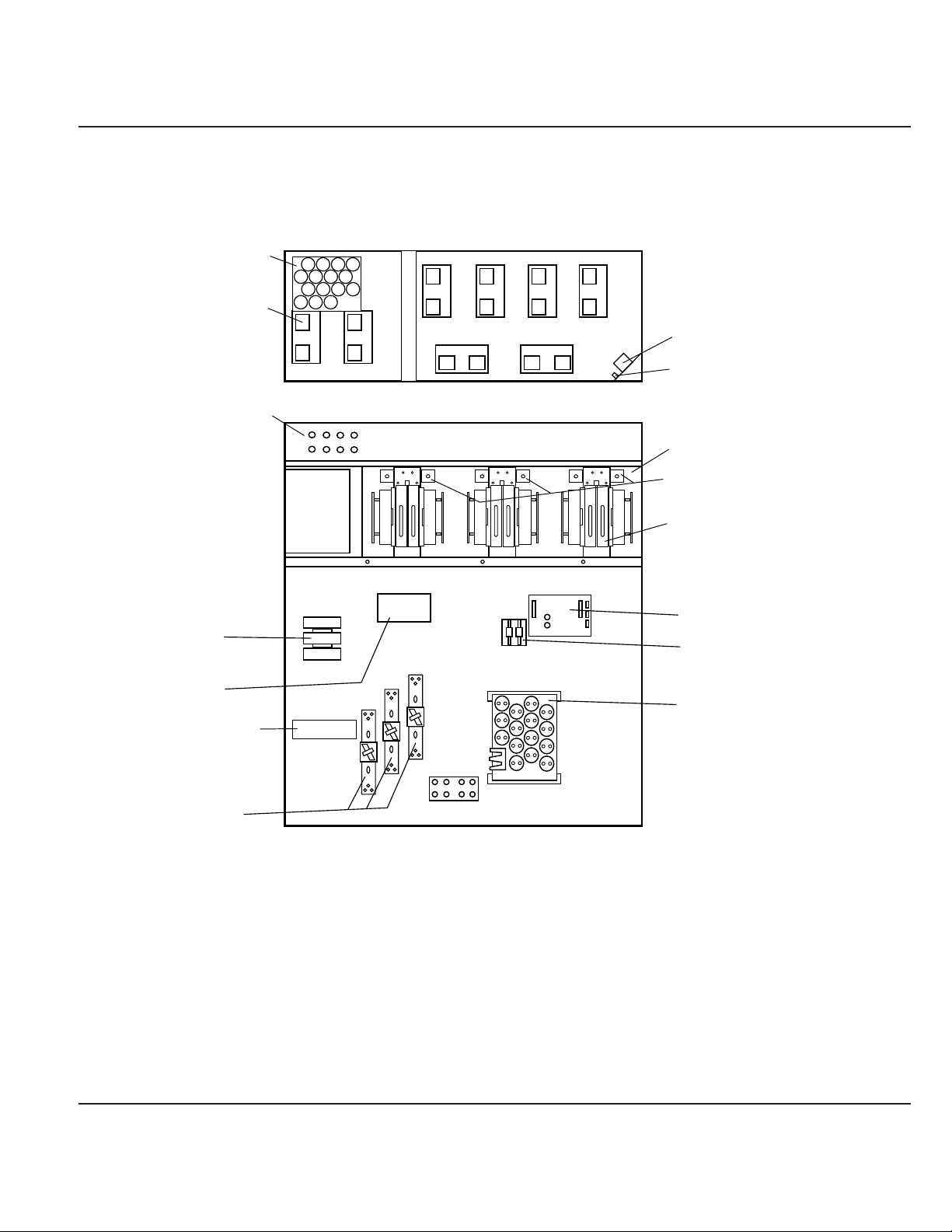
Figure EPS 6000 Major Internal Components,
1-8 Shared 750 kVA UPS Cabinet 2
1 — 10 Introduction
EPS 6000 UPS Shared Systems
AC CAPACITOR
ASSEMBLY
FANS
(x 8)
FB1 TO FB8
1 2
FB2FB1
FB3
FB6FB5
FB7
7 8
TOP VIEW, COVER REMOVED
FRONT VIEW, DOORS AND COVERS REMOVED
FB4
FB8
21
43
543
FAN
TRANSFORMER
FB9
DC CAPACITORS
(BEHIND EACH INVERTER)
INVERTER FUSES (BEHIND)
665
F24,F26,F28,F30,F32,F34
INVERTERS (x6)
K3N
K3NZ
STATIC SWITCH
OUTPUT FUSES
ALBZ
F10,F11
AC OUTPUT
CAPACITORS
NEUTRAL
Page 21
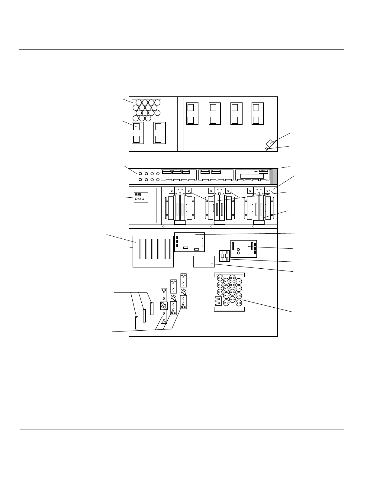
Figure EPS 6000 Major Internal Components,
1-9 Shared 750 kVA UPS Cabinet 3
1 — 11Introduction
User’s guide
AC CAPACITOR
ASSEMBLY
FANS
(x 8)
1 2
TOP VIEW, COVER REMOVED
FB1 TO FB8
EPOZ
CARD CAGE:
1- GTCZ PCA
2- SRIZ PCA
3- CRIZ PCA
4- CROZ / DO6Z PCA
5- AROZ PCA
6- ALEZ PCA
1
FRONT VIEW, DOORS AND COVERS REMOVED
FB4
FB2FB1
FB3
RAUZ PCA
FB8
FB6FB5
FB7
21
23456
OBEZ PCA
43
543
FAN
TRANSFORMER
FB9
IBEZ PCA
DC CAPACITORS
(BEHIND EACH INVERTER)
INVERTER FUSES (BEHIND)
665
F24,F26,F28,F30,F32,F34
INVERTERS (x6)
DOUZ
ALBZ
F10,F11
ACOZ
POWER
INTERCONNECT
OUTPUT FUSES
AC OUTPUT
CAPACITOR ASSY
Page 22
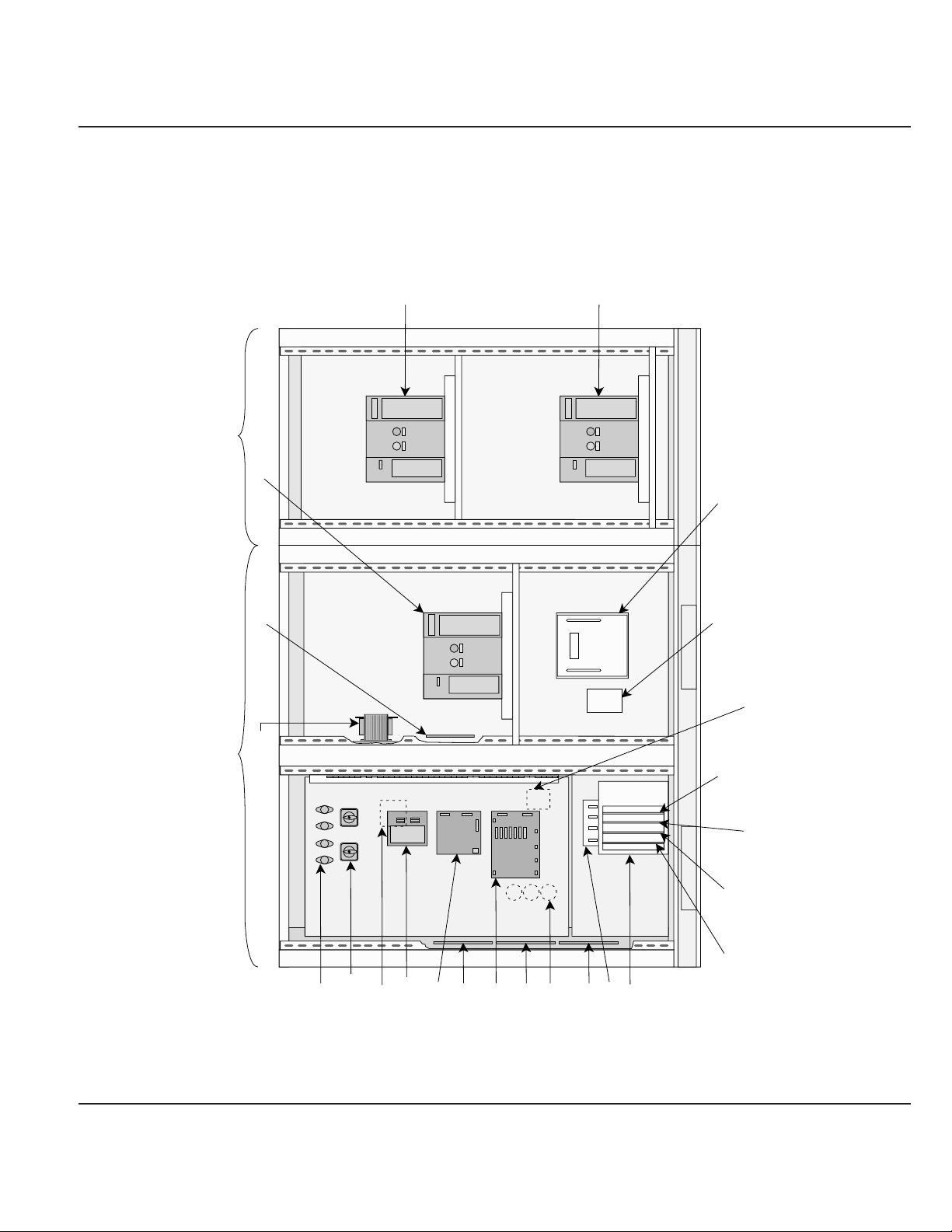
Figure EPS 6000 Major Internal Components,
1-10 Static Switch Cabinet (SSC)
1 — 12 Introduction
EPS 6000 UPS Shared Systems
CIRCUIT BREAKER
(Q3BP)
CIRCUIT BREAKER
(Q2S)
(WITH FRONT DOOR REMOVED)
MAINTENANCE BYPASS CABINET
CIRCUIT BREAKER
(Q5N)
STATIC SWITCH
PCA (CBOZ)
BYPASS
TRANSFORMER (T12)
STATIC SWITCH CABINET
(WITH FRONT DOORS REMOVED)
UPS
BYPASS
UPS
FUSES
(SW1, & SW2)
(F1, F2, F3, & F4)
ROTARY SWITCHES
TRANSFORMER (T13)
PCA (EPOZ)
PCA (ACOZ)
FAR SIDE OF PANEL
PCA (ACPZ)
PCA (RAUZ)
PCA (OBEZ)
CAPACITORS
(C11, C12, & C13)
PCA (IBEZ)
PCA (PROZ)
CARD CAGE
FAR SIDE OF PANEL
STATIC SWITCH PCA
(SSSZ)
FAR SIDE OF PANEL
FUSES (F11, F12, & F13)
PCA (GTCZ)
PCA (SRIZ)
PCA (AROZ)PCA (ALEZ)
Page 23

This section describes options available for the EPS 6000
UPS. Some configurations do not support some options.
Most options must be specified at the time of equipment order; some options can be installed
in the field. Contact your MGE dealer for complete information.
Additional battery cabinets
Up to a maximum of four battery cabinets can be supplied for a single EPS 6000 UPS
module, making additional back-up time available during power outages.
Input filter
An input harmonic current filter is available for the EPS 6000 UPS. For some power levels,
the input filter is installed within the UPS enclosure. For others, the input filter is installed
in an auxiliary cabinet.
High interrupting capacity circuit breakers
The EPS 6000 UPS module is normally equipped with circuit breakers rated at 30 kAIC.
As an option, these breakers can be provided with a rating of 65 kAIC.
Maintenance bypass
For the UPS modules, maintenance bypass is provided by the SSC, allowing any or all
attached UPS modules to be taken off-line while the SSC supports the attached load from
its bypass source. As an option, the SSC can be equipped with its own maintenance
bypass, allowing the SSC as well as any/all attached UPS modules to be serviced while
the load is supported by the maintenance bypass AC input source.
Active RS-232/RS-485
A communications port is available that allows the UPS module or the SSC to be
monitored from a remote terminal or computer. For detailed information on the communication features, contact your MGE dealer.
Specifications provided refer to an EPS 6000 UPS module
and any required auxiliary cabinets.
AC input ratings
Voltage: 208 or 480 VAC, +10%, -15%
Frequency: 60 Hz, ± 10%
Phases: 3 Ø (phase sequence must be A, B, C)
Wires: 3 or 4 wires plus ground
Current:
Power factor: Up to 0.9 lagging; 0.95 with optional input har monic filter
1.5.1 Electrical
1.5 Specifications,
UPS Modules
1.4 Options
1 — 13Introduction
User’s guide
AVknignitar051522003573005057
CAV084@serepmA002003004094207089
Page 24

AC output ratings
Voltage: 480 VAC ± 0.5% (steady-state conditions)
480 VAC ± 5% (transient conditions
from 0% to 100% or 100% to 0%)
Frequency: 60 Hz ± 0.1% (free-r unning)
Phases: 3 Ø (phase sequence must be A, B, C)
Wires: 4 wires plus ground
Current:
Power factor: 0.8 lagging
Total har monic distor tion
(THD): < 2% (linear load)
< 4% (for 100% non-linear load
with a crest factor of up to 3.5)
Dynamic regulation: ± 0.5% for balanced load
± 2.5% for 100% unbalanced load
Dynamic response: ± 5% for 100% step load change
Overload: 125% of rated load for 10 minutes
150% of rated load for 1 minute
DC ratings
Battery voltage: 545 Vdc float
480 Vdc nominal
390 Vdc minimum
Height: 1,905 mm (75”)
Depth: 815 mm (32”)
Width: See Table 1-1
Weight: See Table 1-1
Finish: MGE light gray
1.5.2 Mechanical
1 — 14 Introduction
EPS 6000 UPS Shared Systems
AVknignitar051522003573005057
CAV084@serepmA081172163154106209
AVknignitar051522003573005057
tnerrucyrettabmumixaM
)CDA(egatlovffo-tucta
323584746908470,1026,1
Page 25

Recommended environment: 20° to 25° C (68° to 77° F.); 50% relative humidity;
computer room or other temperature- and humidity-
controlled environment
Operating temperature: 0° to 40° C (32° to 104° F.) except battery
Storage: -20° to 50° C (-4° to 122° F.)
Humidity: up to 90% non-condensing (operating)
Altitude: sea level to 1,000 meters (sea level to 3,280 feet)
without derating; 1,000 to 2,000 meters (3,280
to 6,560 feet): derate operating temperature to a
maximum of 28° C (82° F)
Acoustic noise:
AC input ratings
V oltage: 480 VAC, ± 15%
Frequency: 60 Hz, ± 10%
Phases: 3 Ø (phase sequence must be A, B, C)
Wires: 3 or 4 wires plus ground
Current: 2,000 Amperes
AC output ratings
V oltage: 480 VAC
Frequency: 60 Hz
Phases: 3 Ø
Wires: 4 wires plus ground
Current: 2,000 Amperes
Power factor: 0.8 lagging
1.6.1 Electrical
1.6 Specifications,
Static Switch
Cabinet
1.5.3 Environmental
1 — 15Introduction
User’s guide
AVknignitar051522003573005057
detartaesioncitsuoccA
teef5taABdnidaol
fotnorfehtmorf
eludomSPUeht272727275787
Page 26

Height: 1,981 mm/78 in.
Depth: 1,219 mm/48 in.
Width: 1,829 mm/72 in.
Weight: 1,310 kg/2,900 lbs. (SSC)
1,091 kg/2,000 lbs. (MBC)
Finish: MGE light gray
1.6.2 Mechanical
1 — 16 Introduction
EPS 6000 UPS Shared Systems
Page 27

This section presents operating information for EPS 6000
UPS shared systems, including an overview of the system,
its components, and their function; a description of the indicators and controls and their
function; and operational sequences to be followed for all conditions of normal, emergency,
and maintenance operation.
This section presents an overview of system operation.
During normal operation (as shown in Figure 2-1),
and on-battery operation (shown in Figure 2-2), the
attached load is supplied by the UPS modules through
the SSC. The SSC maintains synchronization of
the UPS modules, and monitors their proper performance.
If all UPS modules have stopped, for instance during an overload condition or maintenance,
the attached load is supplied by the SSC’s bypass input source.
If the SSC is equipped with the maintenance bypass option, the load may still be supplied with
power while the SSC is serviced, via the maintenance bypass AC input source.
Figure Power Flow, Normal Operation
2-1
2.1.1 Static Switch
Cabinet Operation
2.1 System Operation
Overview
2.0 Scope
2 — 1
Operation
Q2S
Bypass AC input
(mains 2)
Main AC input
(mains 1)
Additional
modules
Rectifier/battery
charger
Battery
Rectifier/battery
charger
Battery
Inverter
UPS module
Inverter
UPS module
Static switch
Additional
modules
Static switch
cabinet (SSC)
TO
ATTACHED
LOAD
Page 28
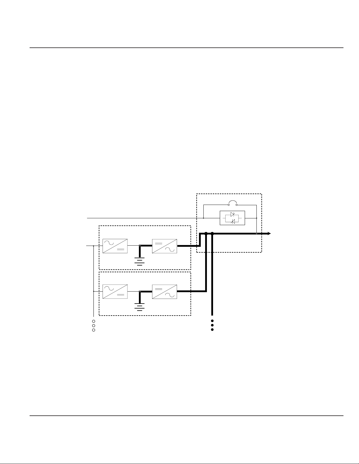
During normal operation (as shown in Figure 2-1), power
flows from the main AC input source (mains 1) into the UPS
rectifier/battery charger sections. The rectifier/battery chargers convert the AC voltage to DC,
maintain the charge on the batteries, and feed the DC power to the inverters. The inverters
regenerate AC voltage, and supply the SSC’s UPS module AC output bus. The SSC supplies
the attached load.
If the main AC input source (mains 1) fails or goes out of
tolerance, the chargers stop. Power flows from the batteries
to the UPS inverters, which in turn supply the attached load (as shown in Figure 2-2). When
the main AC input source (mains 1) returns, the chargers restart automatically and the UPS
system resumes its normal operation (as shown in Figure 2-1).
If the batteries become depleted before the main AC input source (mains 1) returns, the
inverters stop and the attached load is transferred to the bypass AC input source (mains 2) if it
is available (as shown in Figure 2-3).
Figure Power Flow, On-Battery Operation
2-2
2.1.3 On-Battery Operation
2.1.2 Normal Operation
2 — 2 Operation
EPS 6000 UPS Shared Systems
Bypass AC input
(mains 2)
Main AC input
(mains 1)
Rectifier/battery
charger
Inverter
Q2S
Static switch
cabinet (SSC)
Static switch
TO
ATTACHED
LOAD
Additional
modules
Battery
Rectifier/battery
charger
Battery
UPS module
Inverter
UPS module
Additional
modules
Page 29

Figure Power Flow, Bypass Operation
2-3
Indicators and controls are located in three places on the
UPS module: on the front panel, behind a drop-down cover
just below the front panel, and inside the enclosure doors,
as shown in Figure 2-4. In battery cabinets and auxiliar y
cabinets, the controls are located behind the cabinet doors.
The front panel, shown in Figure 2-5, includes the
emergency power off (EPO) pushbutton, the audible alarm,
four LEDs that serve as system status indicators (three on the SSC), and the “inverter on” and
“inverter off” pushbuttons (on UPS modules only).
2.2.1 Front Panel
2.2 Indicators and
Controls
2 — 3Operation
User’s guide
Bypass AC input
(mains 2)
Main AC input
(mains 1)
Additional
modules
Rectifier/battery
charger
Battery
Rectifier/battery
charger
Battery
Inverter
UPS module
Inverter
UPS module
Static switch
Additional
modules
Q2S
Static switch
cabinet (SSC)
TO
ATTACHED
LOAD
Page 30

Figure EPS 6000 Controls and Indicators
2-4
Figure
EPS 6000 Front Panel
2-5
Note:The SSC does not include inverter on or inverter off pushbuttons #6 and #7,
or the battery operation LED #4.
2 — 4 Operation
EPS 6000 UPS Shared Systems
Front
panel
Alphanumeric
display
Hidden
panel
Cover
Circuit breakers
and switches
behind
cabinet
door
Page 31

Emergency power off (EPO)
On the left side of the front panel, an emergency power off (EPO) pushbutton is
provided, with a protective cover to guard against inadvertent operation. This
pushbutton, when activated on a UPS module, disconnects the main AC input
(mains 1), and battery power to the module, and disconnects output power to the
SSC’s UPS module AC input bus. When activated on the SSC, it sends a shunt
trip signal to the upstream protective device (Q4S) supplying the bypass AC input
(mains 2) source, and sends an EPO command to each UPS module (see above),
disconnecting the attached load.
Audible alarm (Figure 2-5, item 1)
The audible alarm provides an audible warning to the operator by sounding a
pulsed “beep” when any of the following conditions occur:
• Load transferred to bypass (mains 2)
• Load supplied via battery
• Operating problem
During minor alarm conditions, the alarm sounds at a slow rate and a low sound
level. When the batter y approaches the low-voltage shutdown level, the alarm
sounds louder and at an increased rate. If the inverter shuts down, the alarm
sounds loudly and continuously.
An audible alarm reset is located on the hidden panel (see Figure 2-7). Pressing it
will silence the alarm. Should a higher-level alarm condition occur after the reset
has been activated, the audible alarm will sound the new alarm condition.
¡
Load not protected LED (2)
This red LED turns on when any of these conditions occur:
• The load is no longer protected following an inverter shutdown, or the
opening of the isolation circuit breaker (Q5N)
• The battery circuit breaker QF1 is open, making battery power unavailable
2 — 5Operation
User’s guide
Pressing the EPO disconnects the attached load.
The emergency power off (EPO) is to be used
during emergency situations only, where a hazard
to personnel or equipment exists, such as during a
fire. DO NOT USE THE EPO TO TURN THE UPS ON
OR OFF; follow the procedures listed in this
section for turning on and off the inverter.
CAUTION
Page 32

⁄
Operating problem LED (3)
This orange LED turns on when an operating problem exists, such as fan failure;
static switch power supply fault; battery temperature fault; overload fault; or bypass
AC input (mains 2) out of tolerance. The UPS continues to protect the attached
load.
ı
Battery operation LED (4) (UPS modules only)
This orange LED turns on to indicate that the attached load is being partially or
completely supplied by the battery. When the main AC input (mains 1) fails or is
outside tolerance, stored battery energy is supplied to the inverter, which in turn
supplies the load.
Í
Load protected LED (5)
This green LED indicates that the attached load is supplied by the inverter
and protected by the battery. Dur ing normal operation, this LED is
the only one that is on.
Inverter on (6) (UPS modules only)
This green pushbutton is used to start the inverter. When it is pushed, the green
“load protected” LED flashes for three seconds, indicating that the start command
has been received. When the transfer conditions are satisfied
(see Section 2.4.2, Start-up, and Section 2.4.6, Forced Transfers),
the load is transferred to the inverter output.
Inverter off (7) (UPS modules only)
This gray pushbutton is used to stop the inverter. When it is pressed for 3
seconds, the inverter stops and the UPS module is shut down; if all UPS modules
are stopped, the load is transferred to the bypass AC input (mains 2) power
source. If the uninterrupted transfer conditions are not met, this pushbutton has no
effect and the inverter can be stopped only from the hidden panel (see Section
2.4.6, Forced Transfers). See Section 2.4.2 for details of the shutdown sequence.
The alphanumeric display is located on the hidden panel,
directly below the front panel, behind the hinged cover, as
shown in Figure 2-4. For complete instructions, refer to
Section 2.3, Using the Alphanumeric Display. A brief
description of the display and controls follows:
Two-line alphanumeric display (Figure 2-6)
This 40-character, two line LCD displays general status of the UPS continuously,
and displays measurements of UPS operating parameters as selected with
the control pushbuttons.
2.2.2 Alphanumeric
Display and
Controls
2 — 6 Operation
EPS 6000 UPS Shared Systems
Page 33

Pushbuttons
Following are brief descriptions of the function of the alphanumeric display
pushbuttons.
Figure Alphanumeric Display and Controls
2-6
ø
Settings pushbutton
This pushbutton is used to select the display language and adjust the LCD screen
contrast for optimal viewing.
˘
Pushbutton
This pushbutton primarily allows the selection of which UPS module or SSC the
display communicates with; it may also serve to indicate selection, negative
response, and other functions, depending on the displayed message.
◊
Pushbutton
This pushbutton provides access to voltage measurements, including:
• Main AC input (mains 1) phase-to-phase voltage
• Bypass AC input (mains 2) phase-to-neutral and phase-to-phase voltage
• Inverter output phase-to-neutral and phase-to-phase voltage
• Load phase-to-neutral and phase-to-phase voltage
Å
Pushbutton
This pushbutton provides access to current measurements, including:
• Main AC input (mains 1) current
• Bypass AC input (mains 2) current
2 — 7Operation
User’s guide
LOAD IS PROTECTED
UPS IS ON LINE
LCD
display
Settings
pushbutton
˘
pushbutton
87654321
W.HzAV
+–
!
*
Page 34

• Inverter current
• Load current
• Percent current drawn by the load relative to UPS module or SSC rating
• Crest factor per phase
„
Pushbutton
This pushbutton provides access to power and
frequency measurements, including:
• Main AC input (mains 1) frequency
• Bypass AC input (mains 2) frequency
• Inverter frequency
• Power drawn by the load (in kW and kVA)
• Load power factor
ı
Battery pushbutton
This pushbutton provides access to battery measurements, including:
• Battery voltage
• Battery current
• Battery ambient temperature
• Battery time available
• Battery time remaining
⁄
Alarms pushbutton
This pushbutton is used to display current alarms, or to display stored alarms.
If the alarm key is pressed repeatedly, the display will scroll through the stored
alarm record, returning to the latest after the oldest is shown.
If a blinking character (!) appears in the display, the user may press the Alarm
pushbutton again to scroll through additional useful information.
Ø
pushbutton
This pushbutton is reserved for future use.
°
Pushbutton
Depending on the displayed message, this pushbutton may serve to indicate confirmation, positive response, and other functions.
2 — 8 Operation
EPS 6000 UPS Shared Systems
Page 35

Numbered lights
The green light indicates the UPS module or SSC with which the display is
currently communicating.
A red light indicates that the corresponding UPS module or SSC has
an anomaly or is not communicating with the display.
Light #1 refers to the SSC; the UPS modules are numbered sequentially
starting at #2.
The hidden panel is located directly below the front panel,
behind the hinged cover, as shown in Figure 2-4. The
hidden panel includes the following controls and indicators, as shown in Figure 2-7:
Figure Hidden Panel
2-7
Alphabetical lights
Fourteen alphabetically labeled LEDs provide detailed information on
UPS status as follows:
A: Emergency shutdown
This red LED indicates that the emergency power off (EPO) or remote emergency
power off (REPO) has been activated (see Section 2.4.4.1, Emergency power off).
2.2.3 Hidden Panel
2 — 9Operation
User’s guide
Emergency shutdown
Rectifier/charger fault
Rectifier/charger on
Battery temp. outside tolerance
Input outside tolerance
T
est connector
Low batt. shutdown imminent
Battery charging
fault
Clear faults
Inverter desynchronized
Inverter fault
12 345
Alarm reset
Return to float voltage
Battery charge cycle
Bypass outside tolerance
T
ransfer fault
Security
Maintenance position
Overload
NMLKJIHGFEDCBA
Inverter sync/desync
Forced transfer
Forced shutdown
Page 36

B: Rectifier/charger on
This green LED indicates that the rectifier/battery charger is on.
C: Rectifier/charger fault
This red LED indicates an alarm condition within the rectifier/battery charger. it
indicates the presence of one of the following fault conditions:
• Input circuit breaker Q1 open
• Input power protection fuse blown
• Rectifier/battery charger over-temperature
• Battery charge overcurrent
• Battery overvoltage
• Rectifier/battery charger control board fault
• Power supply board fault
D: Main AC input (mains 1) outside tolerance
This orange LED indicates that the main AC input (mains 1) source is outside
tolerance (voltage and/or frequency too high or too low).
E: Reserved for future use.
F: Battery temperature outside tolerance
This orange LED indicates that the ambient temperature of the battery is
too high or too low.
G: Battery charging
This orange LED indicates that the battery is being recharged. This LED functions
only when the connected battery is of the vented lead-acid type (sealed lead-acid
batteries will not activate this signal).
H: Inverter fault
This red LED indicates an alarm condition in the inverter, which may be one or
more of the following conditions:
• Inverter shutdown due to output voltage out of tolerance
• Inverter output protection fuse blown
• Inverter leg fault
• Inverter output transformer over-temperature
• Inverter leg over-temperature
• Current sharing fault
• Internal clock fault
• Inverter control board fault
• Power supply board fault
I: Battery discharged
This orange LED indicates that the battery has reached the end of its autonomy,
shutting down the inverter.
2 — 10 Operation
EPS 6000 UPS Shared Systems
Page 37

J: Inverter desynchronized
This orange LED indicates that the inverter output frequency is not synchronized
with the bypass AC input (mains 2).
K: Transfer fault
This red LED indicates a transfer fault, which may be one or
more of the following conditions:
• Inverter output contactor K3N fault
• Current sharing relay fault
• Static switch power supply fault
• Transfer control board fault
• Power supply board fault
L: Overload
This orange LED indicates an alarm condition resulting from one
or more of the following conditions:
• UPS module inverter current above rating
• UPS module output current above rating
• SSC output current above rating
• UPS module and/or SSC shutdown due to excessive load current
M: Bypass AC input (mains 2) outside tolerance
This orange LED indicates that the bypass AC input (mains 2) voltage and/or
frequency are too high or too low.
N: Maintenance position
This orange LED indicates that circuit breakers QF1, Q4S, Q5N, or Q3BP
are set to the maintenance position. The UPS module or SSC is
not available for load protection.
Test connector (Figure 2-8)
This 9-pin connector is reserved for service. It is used to connect
the cabinet to a computer, allowing system calibration, personalization,
and computer-aided diagnostics.
Pushbuttons
Following are brief descriptions of the function of the hidden panel pushbuttons,
shown in Figure 2-8.
Clear fault log
Pressing this pushbutton clears the alarms stored in memory, allowing the unit to
restart. Memorized alarms cannot be cleared until the condition causing the alarm
has been corrected.
Audible alarm reset
Pressing this pushbutton stops the audible alarm. Should a new fault condition at
a higher alarm level occur, the alarm will sound again.
2 — 11Operation
User’s guide
Page 38

Figure Hidden Panel Pushbuttons
2-8
Battery charge cycle (pushbutton #1) (applies to UPS module only)
Pressing this pushbutton begins a battery charging cycle. After the cycle is
complete, the rectifier/battery charger returns to float charge levels on the battery.
The battery charge cycle is not applicable to sealed lead-acid battery installations.
Return to float voltage (pushbutton #2) (applies to UPS module only)
This pushbutton can be used during a battery charge cycle to force the
rectifier/battery charger back to the float voltage level.
Security pushbutton (key)
This pushbutton must be pressed simultaneously with any of the following
three pushbuttons. This helps guard against inadvertent transfer
of the load with interruption.
Inverter desync/sync (pushbutton #3) (applies to SSC only)
Pressing and holding the “security key”while pressing this pushbutton
forces the inverter output to desynchronize or synchronize to the
bypass AC input (mains 2) source.
2 — 12 Operation
EPS 6000 UPS Shared Systems
Test
connector
Clear
fault log
pushbutton
Audible
alarm
charge cycle
pushbutton
reset
Battery
Security (key)
pushbutton
12 345fault
Return to
float voltage
pushbutton
Inverter
desync/sync
pushbutton
Forced inverter to
bypass pushbutton
NMLKJIHGFEDCBA
Forced bypass
to inverter
pushbutton
CAUTION
Using the forced transfer functions will cause the
load to experience an interruption for a minimum of
0.8 seconds. Be certain the the load can tolerate
this interruption; see Section 2.4.6, Forced
Transfers.
Page 39

Forced bypass to inverter (pushbutton #4) (applies to SSC only)
Pressing and holding the “security key”while pressing this pushbutton forces the
transfer of the load to the inverter output when the bypass is out of tolerance.
Enough UPS modules must have been started; press the “inverter on” pushbutton
on their front panels if necessary. The load will experience a 0.8 second inter-
ruption. Refer to Section 2.4.2, Start-up, and Section 2.4.6, Forced Transfers.
Forced inverter to bypass (pushbutton #5) (applies to UPS module only)
Pressing and holding the “security key”while pressing this pushbutton stops the
inverter and disconnects the module from the load, even if the bypass is out of
tolerance; if all UPS modules are stopped, the load will be transferred to
bypass with a 0.8 second interruption. Refer to Section 2.4.6, Forced Transfers.
EPS 6000 circuit breakers and switches (except the
battery disconnect circuit breaker QF1) are located behind
the doors of the UPS cabinet, or through the door in the
optional MBC. Following is a brief description of the
available circuit breakers, contactors and switches, and
their function. The single-line diagram in Figure 2-9
shows the location of each circuit breaker, contactor and switch within the electrical path,
and Figure 2-10 thorugh Figure 2-17 show the location of each switch, contactor and circuit
breaker within the enclosures.
Upstream of the SSC:
Q4S Customer-supplied upstream circuit breaker, used to isolate the SSC from the bypass AC
input (mains 2) source and provide backfeed protection.
In the SSC (and optional MBC):
Q2S Wrap-around circuit breaker (automatic), used to supply the attached load via the bypass
AC input (mains 2) source.
Q3BP (Optional), system maintenance bypass circuit breaker, used to supply the attached load
via the maintenance bypass source while the SSC is being serviced.
Q5N (Optional), system isolation circuit breaker, used to isolate the shared system from the
2.2.4 Circuit Breakers,
Contactors and
Switches
2 — 13Operation
User’s guide
CAUTION
Using the forced transfer functions will cause the
load to experience an interruption for a minimum of
0.8 seconds. Be certain the the load can tolerate
this interruption; see Section 2.4.6, Forced
Transfers.
Page 40

attached load.
Figure Single-Line Diagram,
2-9 Typical EPS 6000 UPS Shared Installation
2 — 14 Operation
EPS 6000 UPS Shared Systems
MAINTENANCE
BYPASS
AC INPUT
BYPASS
AC INPUT/
MAINS 2
MAIN
AC INPUT/
MAINS 1
Q4S
(CUSTOMER
SUPPLIED)
EPS 6000 UPS MODULE
Q1
INPUT
FUSES
EPS 6000 UPS MODULE
Q1
INPUT
FUSES
RECTIFIER/
CHARGER
EPS 6000
BATTERY
RECTIFIER/
CHARGER
EPS 6000
BATTERY
INVERTER
QF1
INVERTER
QF1
STATIC SWITCH
OUTPUT
FUSES
STATIC SWITCH
OUTPUT
FUSES
K3N
K3N
STATIC SWITCH
STATIC SWITCH
Q2S
Q5N
Q5N
CABINET
FROM ADDITIONAL
UPS MODULES
MAINTENANCE
BYPASS CABINET
(OPTIONAL)
Q38P
Q5N
TO
ATTACHED
LOAD
Page 41

Figure EPS 6000 Major Internal Components,
2-10 Shared 150 - 225 kVA UPS Module
2 — 15Operation
User’s guide
AC CAPACITOR
ASSEMBLY
FANS
(x 6)
1 2
TOP VIEW, COVER REMOVED
FB1 TO FB8
F10,F11 RATED 2A,500VDC
CHARGER, STATIC SW,
CARD CAGE:
1- GTCZ PCA
2- SRIZ PCA
3- CRIZ PCA
4- CROZ / DO6Z PCA
5- AROZ PCA
6- ALEZ PCA
INPUT FUSES F1, F2, F3
F12,F13
EPOZ
BAIZ & TREZ
(BEHIND PLATE)
ALBZ
FUSES F16, F17
F18, F19
INPUT
CONNECTIONS
FRONT VIEW, DOORS AND COVERS REMOVED
FB4
FB2FB1
FB3
RAUZ PCA
FB8
FB6FB5
FB7
OBEZ PCA
K3N
23456
1
Q1 Q5N
C3B3A3
GROUND
CONNECTIONS
+
BATTERY
CONNECTIONS
6543
C4B4A4
OUTPUT
CONNECTIONS
FAN
TRANSFORMER
FB9
IBEZ PCA
DC CAPACITORS
(BEHIND EACH INVERTER)
INVERTER FUSES (BEHIND)
INVERTERS
OUTPUT FUSES F7, F8, F9
120V AC OUTLET
(FOR MGE USE ONLY)
ARUZ PCA (BEHIND MTG. PLATE)
ACPZ PCA
APOZ PCA
OUTPUT XFMR
(BEHIND BREAKERS)
OUTPUT
CIRCUIT BREAKER
NEUTRAL CONNECTION
(BEHIND OUTPUT)
K3NZ PCA
Page 42

Figure EPS 6000 Major Internal Components,
2-11 Shared 300 / 375 kVA UPS Module
2 — 16 Operation
EPS 6000 UPS Shared Systems
AC CAPACITOR
ASSEMBLY
FANS
(x 6)
1 2
TOP VIEW, COVER REMOVED
FB1 TO FB8
F10,F11 RATED 2A,500VDC
CHARGER, STATIC SW,
CARD CAGE:
1- GTCZ PCA
2- SRIZ PCA
3- CRIZ PCA
4- CROZ / DO6Z PCA
5- AROZ PCA
6- ALEZ PCA
INPUT FUSES F1, F2, F3
F12,F13
EPOZ
BAIZ & TREZ
(BEHIND PLATE)
ALBZ
FUSES F16, F17
F18, F19
INPUT
CONNECTIONS
FRONT VIEW, DOORS AND COVERS REMOVED
FB4
FB2FB1
FB3
RAUZ PCA
FB8
FB6FB5
FB7
OBEZ PCA
21
43
K3N
23456
1
Q1 Q5N
C3B3A3
GROUND
CONNECTIONS
+
BATTERY
CONNECTIONS
543
CONNECTIONS
665
C4B4A4
OUTPUT
FAN
TRANSFORMER
FB9
IBEZ PCA
DC CAPACITORS
(BEHIND EACH INVERTER)
INVERTER FUSES (BEHIND)
F23 TO F34
INVERTERS (x6)
OUTPUT FUSES F7, F8, F9
120V AC OUTLET
(FOR MGE USE ONLY)
ARUZ PCA (BEHIND MTG. PLATE)
ACPZ PCA
APOZ PCA
OUTPUT XFMR
(BEHIND BREAKERS)
OUTPUT
CIRCUIT BREAKER
NEUTRAL CONNECTION
(BEHIND OUTPUT)
K3NZ PCA
Page 43

Figure EPS 6000 Major Internal Components,
2-12 Shared 500 kVA UPS Module I/O Cabinet
2 — 17Operation
User’s guide
CONNECTION
CONNECTION
NEUTRAL CONNECTION
NEUTRAL
CONNECTIONS
GROUND
TOP VIEW, COVERS REMOVED
FRONT VIEW, DOORS AND COVERS REMOVED
INPUT
A3 B3 C3
Q1
OUTPUT
CONNECTIONS
A4 B4 C4
GROUND CONNECTION
Q5N
BATTERY
CONNECTIONS
BONDING
JUMPER
SHUNT
L2
CURRENT XFMRS
INPUT FUSES
F1,F2,F3
FUSES F16,F17
L3
A12B12 C12
C1B1A1
N12
ACPZ
A2
C2
B2
ARUZ
L4
AC CAPACITORS
Page 44

Figure EPS 6000 Major Internal Components,
2-13 Shared 500 kVA UPS Module UPS Cabinet
)
2 — 18 Operation
EPS 6000 UPS Shared Systems
CARD CAGE:
AC CAPACITOR
ASSEMBLY
FANS
(x 8)
FB1 TO FB8
EPOZ
CHARGER & TREZ
(BEHIND PLATE)
AC OUTPUT
CAPACITORS
1- GTCZ PCA
2- SRIZ PCA
3- CRIZ PCA
4- CROZ / DO6Z PCA
5- AROZ PCA
6- ALEZ PCA
K3NZ
K3N
STATIC SWITCH
OUTPUT FUSES
F7, F8, F9
1 2
7 8
TOP VIEW, COVER REMOVED
FRONT VIEW, DOORS AND COVERS REMOVED
4321
123456
NEUTRAL
543
FAN
TRANSFORMER
IBEZ
OBEZ
665
RAUZ
DC CAPACITERS
(BEHIND EACH INVERTER
INVERTERS (x6)
APOZ
ALBZ
F10,F11,F18,F19
F12,F13
DELAY
BATTERY
CONNECTION
(OPTIONAL)
AC CAP ASSY.
K1
Page 45
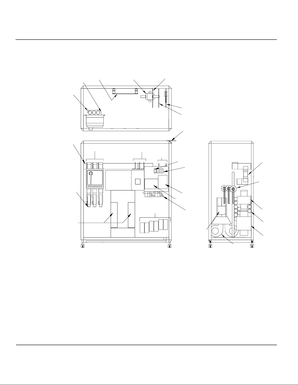
Figure EPS 6000 Major Internal Components,
2-14 Shared 750 kVA UPS Module UPS Cabinet 1
2 — 19Operation
User’s guide
Resistors
Capacitors
Ground
Connection
Input fuses
F1, F2, F3
Input Filter
Capacitors
Neutral
Connection
Input
Connections
A3 B3 C3
Q1
Front view, doors, cover and some components removed for clarity.
Top view
Choke
Output
Connections
A4 B4 C4
Q5N
(optional)
Power
Interconnect
Static Switch
Battery
Connections
(+) (-)
Ground
Connection
ACPZ
Relay
( - )
( + )
Bonding
jumper
Fuses
ARUZ
CT (6ea)
BAIZ
Cooling fans
(2ea)
Side View
Shunt
CT (4ea)
Induction Filter
(2 ea) one on
other side
AC capacitors
(2ea) one on
other side
Induction filter
(2ea) one on
other side
Page 46
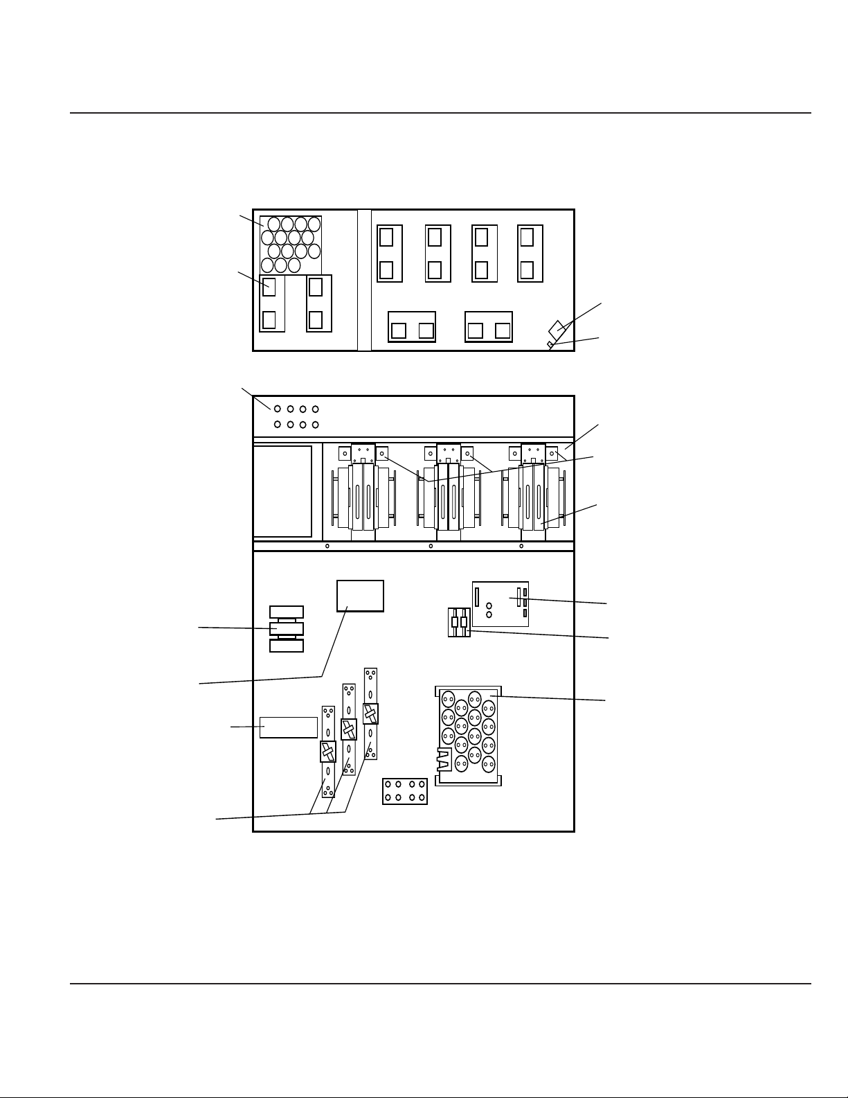
Figure EPS 6000 Major Internal Components,
2-15 Shared 750 kVA UPS Module UPS Cabinet 2
2 — 20 Operation
EPS 6000 UPS Shared Systems
AC CAPACITOR
ASSEMBLY
543
FANS
(x 8)
1 2
7 8
TOP VIEW, COVER REMOVED
FB1 TO FB8
FRONT VIEW, DOORS AND COVERS REMOVED
FB4
FB2FB1
FB3
FB8
FB6FB5
FB7
21
43
FAN
TRANSFORMER
FB9
DC CAPACITORS
(BEHIND EACH INVERTER)
INVERTER FUSES (BEHIND)
665
F24,F26,F28,F30,F32,F34
INVERTERS (x6)
ALBZ
K3N
K3NZ
STATIC SWITCH
OUTPUT FUSES
NEUTRAL
F10,F11
AC OUTPUT
CAPACITORS
Page 47
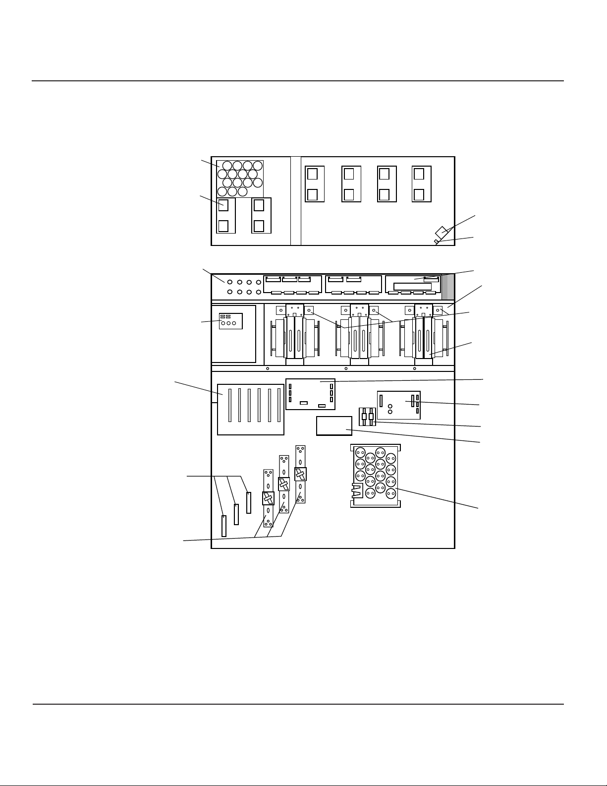
Figure EPS 6000 Major Internal Components,
2-16 Shared 750 kVA UPS Module UPS Cabinet 3
2 — 21Operation
User’s guide
AC CAPACITOR
ASSEMBLY
543
FANS
(x 8)
1 2
TOP VIEW, COVER REMOVED
FB1 TO FB8
EPOZ
CARD CAGE:
1- GTCZ PCA
2- SRIZ PCA
3- CRIZ PCA
4- CROZ / DO6Z PCA
5- AROZ PCA
6- ALEZ PCA
1
FRONT VIEW, DOORS AND COVERS REMOVED
FB4
FB2FB1
FB3
FB6FB5
FB7
RAUZ PCA
FB8
21
OBEZ PCA
23456
43
FAN
TRANSFORMER
FB9
IBEZ PCA
DC CAPACITORS
(BEHIND EACH INVERTER)
INVERTER FUSES (BEHIND)
665
F24,F26,F28,F30,F32,F34
INVERTERS (x6)
DOUZ
ALBZ
F10,F11
ACOZ
POWER
INTERCONNECT
OUTPUT FUSES
AC OUTPUT
CAPACITOR ASSY
Page 48
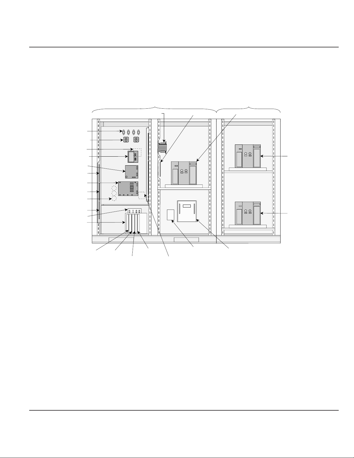
Figure EPS 6000 Major Internal Components,
2-17 Static Switch Cabinet (SSC)
In the UPS modules:
Q1 Input isolation circuit breaker, used to isolate the UPS module from the main
AC input (mains 1) source and provide input current protection.
Q5N UPS isolation circuit breaker, used to isolate the UPS module from he attached load.
K3N Inverter output contactor (automatic), used to isolate the inverter when it is off.
In the circuit of the battery of each UPS module:
QF1 Batter y disconnect circuit breaker, used to disconnect the battery from the UPS. QF1
provides isolation and protection between the UPS module and its battery system.
2 — 22 Operation
EPS 6000 UPS Shared Systems
FUSES
(F1, F2, F3, & F4)
ROTARY SWITCHES
(SW1, & SW2)
TRANSFORMER (T13)
FAR SIDE OF PANEL
PCA (EPOZ)
PCA (ACOZ)
PCA (RAUZ)
PCA (ACPZ)
PCA (OBEZ)
CAPACITORS
(C11, C12, & C13)
FAR SIDE OF PANEL
PCA (IBEZ)
PCA (PROZ)
CARD CAGE
PCA (AROZ)PCA (ALEZ)
STATIC SWITCH CABINET
(WITH FRONT DOORS REMOVED)
TRANSFORMER (T12)
UPS
UPS
BYPASS
BYPASS
PCA (GTCZ)
PCA (SRIZ)
FUSES (F11, F12, & F13)
FAR SIDE OF PANEL
PCA (CBOZ)
STATIC SWITCH PCA
(SSSZ)
MAINTENANCE BYPASS CABINET
(WITH FRONT DOOR REMOVED)
CIRCUIT BREAKER
(Q2S)
STATIC SWITCH
CIRCUIT BREAKER
(Q3BP)
CIRCUIT BREAKER
(Q5N)
Page 49

This section describes operation and use of the alphanu-
meric display in detail.
The alphanumeric display interacts with the user via the top
half of the hidden panel (Figure 2-4). Figure 2-18 shows
the general organization of the alphanumeric display.
During normal operation, when there are no alarm conditions present and the load is supplied
by the UPS inverter output, the display will present the general status message:
LOAD IS PROTECTED
UPS IS ON LINE
When there are alarm conditions, the display will present a general alarm message, and the
user can use the “alarm” pushbutton (!) to deter mine the exact cause of the alarm condition
(see Section 2.3.2, Alarms).
The following sections present detailed operating instructions for the alphanumeric display.
Figure Alphanumeric Display
2-18
2.3 Using the
Alphanumeric
Display
2 — 23Operation
User’s guide
LCD
display
Settings
pushbutton
˘
pushbutton
LOAD IS PROTECTED
UPS IS ON LINE
87654321
+–
W.HzAV
!
*
Page 50
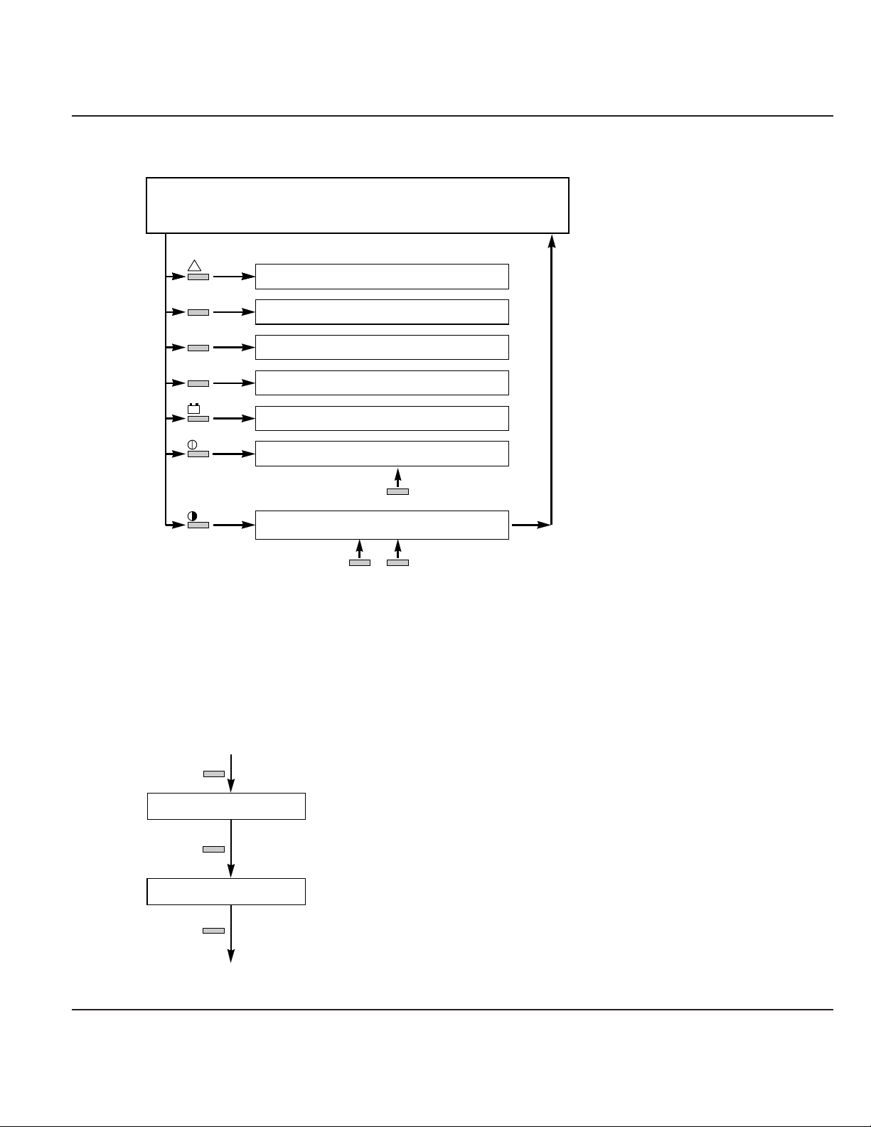
Figure General Display Configuration
2-19
The settings selection screens allow the user to
configure the display language and set the contrast
of the LCD display.
To access the settings selection screen, press the settings pushbutton, and follow the steps as
indicated in Figure 2-20.
Figure Display Settings Display
2-20
2.3.1 Settings
2 — 24 Operation
EPS 6000 UPS Shared Systems
!
V
A
W.Hz
+–
General status screen.
This is the default display. It automatically reappears
if the control panel has not been used for ten minutes.
Alarm display
Voltage measurements
Current measurements
Frequency and power measurements
Battery measurements
Reserved for future use (on/off controls)
*
Language and screen contrast settings
to
set
°≥
to
confirm
to
confirm
LANGUAGE = ENGLISH U.S.
≥=SELECT *=CONFIRM.
ø
°
DISPLAY CONTRAST
≥=SELECT *=CONFIRM.
Press the settings pushbutton to access the
language selection menu.
Select the display language: French, English
(U.K.), Spanish, Dutch, Italian, Swedish,
Portugese, or English U.S.
Press the
selection and access the contrast selection menu.
Set the display contrast by pressing the ≥
pushbutton until the desired contrast is reached.
Press the ° pushbutton to confirm the contrast
selection and return to the general status screen.
°
general status screen
pushbutton to confirm the language
°
Page 51

In the event of an alarm condition, the general status
screen shows an alarm message.To deter mine the specific
condition causing the alarm, press the alarm key on the front panel, as shown in Figure 2-21.
If there is a flashing exclamation mark (!) in the displayed message, there is additional
information to be viewed. Follow the steps as indicated in Figure 2-21.
Most alarm messages are self-explanatory; see Section 2.5 for a listing of the
most common alarm messages.
The most serious alarms are stored in the fault log, and may be viewed by following
the steps shown in Figure 2-21.To reset the alar ms, press the “clear fault log”
pushbutton (see Section 2.2.3).
Figure Displaying Alarm Messages
2-21
2.3.2 Alarms
2 — 25Operation
User’s guide
IMPORTANT
Select ENGLISH U.S. as the display language to
match the displays as presented in this manual.
ALARM
. . . !
(ALARM MESSAGE NUMBER 1)
!
(LAST ALARM MESSAGE)
This message on the general status screen
indicates an alarm condition. The flashing
exclamation mark (
alarm messages to view. To view them, press the
"alarm" pushbutton.
The last alarm message is not followed by an
exclamation mark (
pushbutton is pressed again, the display will
return to the general status screen.
!) indicates that there are
!). When the "alarm"
general status screen
Page 52

The LCD can display comprehensive information about
UPS performance through its monitoring functions.
To display voltage measurements, press the “V” key on the
keyboard, as shown in Figure 2-22.
Figure Voltage Measurements
2-22
2.3.3.1 Voltage
Measurements
2.3.3 Measurements
2 — 26 Operation
EPS 6000 UPS Shared Systems
(Only in UPS modules)
(only in SSC)
(only in SSC)
(only in UPS modules)
Select voltage measurements by
pressing the
◊
INPUT VAB VBC VCA
V RMS
◊
BYPASS VAN VBN VCN
V RMS
◊
BYPASS VAB VBC VCA
V RMS
◊
INV. VAN VBN VCN
V RMS
◊
◊ pushbutton
Main input (mains 1) phase-to-phase voltages
in VAC RMS.
Bypass input (mains 2) phase-to-neutral
voltages in VAC RMS.
Bypass input (mains 2) phase-to- phase
voltages in VAC RMS.
Inverter output phase-to-neutral voltages in
VAC RMS.
(only in UPS modules)
INV. VAB VBC VCA
V RMS
◊
LOAD VAN VBN VCN
V RMS
◊
LOAD VAB VBC VCA
V RMS
◊
Inverter output phase-to-phase voltages in
VAC RMS.
Load phase-to-neutral voltages in VAC RMS.
Load phase-to-phase voltages in VAC RMS.
Page 53

To display current measurements, press the “A” key on the
keyboard, as shown in Figure 2-23.
Figure Current Measurements
2-23
2 — 27Operation
User’s guide
(Only in UPS modules)
Select current measurements by
pressing the
Å
INPUT I1 I2 I3
A RMS
Å
(only in SSC)
BYPASS I1 I2 I3
A RMS
Å
(only in UPS modules)
INV. I1 I2 I3
A RMS
Å
LOAD I1 I2 I3
A RMS
Å
I LOAD / IN
=
% (IN = A)
Å
LOAD I1 I2 I3
CREST F.
Å
Å pushbutton
Main input (mains 1) currents in AAC RMS.
Bypass input (mains 2) currents in AAC RMS.
Inverter output currents in AAC RMS.
Load currents in AAC RMS.
Highest current drawn by a load phase, relative to
the current rating of the UPS module or SSC (IN).
Load crest factor for each phase.
Page 54

To display power or frequency measurements, press the
“W.Hz” key on the keyboard, as shown in Figure 2-24.
Figure Power and Frequency Measurements
2-24
2.3.3.3 Power and
Frequency
Measurements
2 — 28 Operation
EPS 6000 UPS Shared Systems
Select power and frequency measurements
by pressing the
FREQ. INP. BYP. INV.
HZ
LOAD P1 P2 P3
KW
P LOAD / Pn
= %
LOAD P1 P2 P3
KVA
P. TOTAL P.KW P.KVA
LOAD
„ pushbutton.
„
„
„
(PN= KW)
„
„
„
Frequency in Hertz for the main input (mains 1),
bypass input (mains 2), and inverter output.
Real power drawn by the load in kilowatts, for
each phase.
Percentage of real power drawn by the load,
relative to the rated output of the UPS module or
SSC.
Apparent power in kVA drawn by the load for
each phase.
Total real power (in kW) and apparent power (in
kVA) drawn by the load.
POWER FACTOR
LOAD P.F. =
„
Load power factor (real power divided by
apparent power)
Page 55

To display battery voltage, current, ambient temperature,
and time available or remaining, press the battery key on
the keyboard, as shown in Figure 2-25.
Figure Battery Measurements
2-25
This section presents normal operating procedures for the
EPS 6000 UPS.
It is best to contact MGE Customer Support Services
for start-up and maintenance of the EPS 6000 UPS. Do not allow unqualified personnel
to operate the EPS 6000.
Before starting the EPS 6000 UPS, make certain that these
conditions exist (as applicable to your installation):
• All power and control wires have been properly connected and securely tightened.
• The upstream and downstream protective devices are not tripped, and have been
sized properly for the UPS and load requirements.
• The voltage at each main AC input circuit breaker Q1 and at the bypass input
circuit breaker Q4S is the same as indicated on the UPS nameplate, located inside
the right door of the EPS 6000 UPS module.
• The air filters located inside each EPS 6000 UPS module front door are properly
installed and free of dust, dirt, and debris. Make certain that no objects block the
air intake at the front bottom of the enclosures, and that the air exhaust at the top
rear of the enclosures is free of obstructions.
2.4.1 Checks Before
Start-up
2.4 Normal Operating
Procedures
2 — 29Operation
User’s guide
Select battery measurements by
pressing the "battery" pushbutton.
ı
UBAT.
V
IBAT.
* A
ı
AVAILABLE BAT.TIME
MN %KV LOAD =
OR
°
T BAT.
C
ı
REMAINING BAT. TIME
MN %KV LOAD =
ı
Baattery voltage (VDC), charge (+) or discharge
(–) current (ADC), and battery temperature
(degrees Celsius).
If the main input (main 1) source is available, this
indicates the amount of battery time (in minutes)
available in the event of a main input outage.
If the main input (mains 1) source is out of
tolerance or is unavailable, this indicates the
amount of battery time (in minutes) remaining for
on-battery operation.
Page 56

In the individual UPS modules:
• Input (isolation) circuit breaker Q1 is in the OFF (open) position.
• Battery disconnect circuit breaker QF1 is in the OFF (open) position.
• Output isolation circuit breaker Q5N is in the OFF (open) position.
In the SSC:
• System maintenance bypass circuit breaker Q3BP is in the OFF (open) position (if
present).
• System output isolation circuit breaker Q5N is in the OFF (open) position (if
present).
• Input power supply switches SW1 and SW2 are in the ON (closed) position.
• The upstream bypass AC input (mains 2) circuit breaker (Q4S, customer-supplied)
is in the OFF (open) position.
• If present, the upstream maintenance bypass circuit breaker (customer-supplied) is
in the OFF (open) position.
The following start-up procedure should be performed
during the initial start-up following installation of the system,
and this sequence should be followed any time that the EPS 6000 UPS system is being
restarted from an off condition (i.e., after the UPS has been powered down by removing the
upstream AC input power and opening all the circuit breakers of the UPS system).
a. Apply power to Q4S by closing the upstream circuit breaker supplying Q4S,
and the upstream circuit breaker supplying the optional
maintenance bypass input (if present).
b. Apply power to the UPS modules by closing the upstream circuit breaker supplying
the main AC input (mains 1).
c. Star t the SSC:
1. Close the optional system maintenance bypass circuit breaker Q3BP (if
present, in the maintenance bypass cabinet). Power is now available at the
SSC output (the load is energized) via the maintenance bypass source.
2. Close the upstream circuit breaker Q4S that supplies the bypass input to
the SSC. The SSC will come on-line; after about ten (10) seconds, the
wrap-around circuit breaker Q2S will automatically close.
3. Close the optional system isolation circuit breaker Q5N (if present, in the
maintenance bypass cabinet).
4. Open the optional system maintenance bypass circuit breaker Q3BP
(if present). The SSC is now on-line and the load is supplied
via the bypass source.
Note that if your SSC configuration does not include the maintenance bypass option,
start-up requires only closing Q4S to supply the bypass source to the SSC.
All other functions are fully automatic.
2.4.2 Start-up
2 — 30 Operation
EPS 6000 UPS Shared Systems
Page 57
d. Start the UPS modules:
1. For each module, close the input isolation circuit breaker Q1. Verify that
the following conditions exist:
• The red “load not protected” LED is on
• The rectifier/battery charger automatically starts
If either condition is not present, there is a fault. Open Q1 and
contact MGE Customer Support Services.
2. For each module, close the UPS isolation circuit breaker Q5N. The fans in
the UPS module will start.
3. For each module, close the battery disconnect circuit breaker QF1.
The batteries are now connected to the rectifier/battery charger, and
have begun charging.
4. If the modules are not programmed for automatic restart, for each module,
press the “inverter on” pushbutton. The green “load protected” LED will
flash for about 3 seconds, indicating that the inverter is star ting.
5. As soon as a sufficient number of UPS modules have been started, the
SSC will automatically transfer the load to the UPS module output. On
each module, the green “load protected”LED will turn on and remain on.
On the SSC, the green “load protected”LED will turn on.
6. As the remaining UPS modules are turned on (per step 4 above), their
respective green “load protected”LEDs flash for three seconds, then
remain on as the modules connect to the load. The load is equally shared
between modules.
After initial start-up of the system, normal operation should
be tested. At the minimum, the following tests should be
performed (as applicable to your installation):
• Emergency power off (EPO) test from each UPS module, and from the SSC.
2.4.3 Checks After
Start-up
2 — 31Operation
User’s guide
IMPORTANT
Because it is standard for the UPS module to be
programmed for automatic restart, the inverter will
automatically start after the battery disconnect
circuit breaker QF1 has been closed.
If the transfer conditions are not satisfied (bypass
AC input sources is out of tolerance, or some other
reason), a forced transfer is required. Refer to
Section 2.4.6, Forced Transfers.
NOTE
Page 58

• Remote emergency power off (REPO) test (if applicable).
• Inverter start and stop (for each module).
• Battery transfer test.
• Maintenance bypass procedure.
This section presents procedures for shutting down the
system under normal, emergency, overload, and
maintenance conditions.
During an emergency situation, such as a fire in the computer or electrical room, the UPS
and all downstream devices can be instantly shut down by pressing the “emergency power off”
(EPO) pushbutton on the front panel of the SSC, or by pressing the “remote emergency
power off” (REPO) optional pushbutton located within the room.
The EPO or REPO pushbuttons should not be used for normal shutdown of the equipment;
when activated, ground paths may be broken (depending on installation) and sensitive loads
attached to the UPS may lose safety ground connection.
Each UPS module has an EPO feature that can be activated to shut down
that module only (see Section 2.2.1).
2.4.4.1 Emergency
Shutdown
Using EPO
2.4.4 Shut-down
2 — 32 Operation
EPS 6000 UPS Shared Systems
Pressing the EPO disconnects the attached load.
The emergency power off (EPO) is to be used
during emergency situations only, where a hazard
to personnel or equipment exists, such as during a
fire. DO NOT USE THE EPO TO TURN THE UPS ON
OR OFF; follow the procedures listed in this
section for turning the inverter on and off.
CAUTION
Page 59
To shut down an individual UPS module, press the “inverter
off” pushbutton on the module front panel for 3 seconds. To
restart, press the “inverter on” pushbutton. Note that the transfer will occur only if the inverter is
synchronized to the bypass; otherwise, a forced transfer is needed (see Section 2.4.6).
To isolate an individual UPS module for maintenance
(allowing the remaining UPS modules to maintain the
attached load), follow this procedure (starting with all UPS
modules operating normally, supplying the attached load):
1. Stop the inverter by pressing the “inverter off ” pushbutton on the UPS module front
panel for 3 seconds. The audible alarm will sound; silence the alarm by pressing
the audible alarm reset pushbutton on the hidden panel (see Section 2.2.3). If the
transfer conditions are not satisfied (bypass out of tolerance or other reason), a
forced transfer is required;refer to Section 2.4.6, Forced Transfers.
2.4.5.1 Isolation of
an Individual
UPS Module
2.4.5 Isolation for
Maintenance
2 — 33Operation
User’s guide
IMPORTANT
When one UPS module in a shared system is shut
down, it may cause the remaining modules to enter
an overload or current-limiting condition, if they
are unable to fully support the attached load. The
remaining modules may shut down after a certain
time or immediately (depending on the load level),
and the load may be transferred to the bypass AC
input source.
Page 60
2. Open the UPS isolation circuit breaker Q5N.
3. Open the battery disconnect circuit breaker(s) QF1.
4. Open the input isolation circuit breaker Q1.
The UPS module is now isolated for maintenance. For complete protection, the upstream
circuit breaker supplying the UPS module should be opened, locked, and tagged while the
UPS is being serviced.
To restart the UPS module after maintenance:
1. Close the input isolation circuit breaker Q1.
2. Close the isolation circuit breaker Q5N. The UPS module fans will star t.
3. Wait for the green LED “B” on the hidden panel to tur n on (indicating that the
rectifier/battery charger has started), then close the batter y disconnect circuit
breaker QF1. If there is more than one battery cabinet in your configuration, close
all the battery disconnect circuit breakers.
4. If the module is not programmed for automatic restart, start the inverter by
pressing the “inverter on” pushbutton on the UPS front panel. In a few moments,
the inverter will start and the UPS module will resume normal operation.
If the transfer conditions are not satisfied (bypass out of tolerance or other reason),
a forced transfer will be required. Refer to Section 2.4.2, Star t-up, and
Section 2.4.6, Forced Transfers.
2 — 34 Operation
EPS 6000 UPS Shared Systems
When one UPS module in a shared system is shut
down, it may cause the remaining modules to enter
an overload or current-limiting condition, if they
are unable to fully support the attached load. The
remaining modules may shut down after a certain
time or immediately (depending on the load level),
and the load may be transferred to the bypass AC
input source.
IMPORTANT
Because it is standard for the UPS module to be
programmed for automatic restart, the inverter will
automatically start after the battery disconnect
circuit breaker QF1 has been closed.
IMPORTANT
Page 61
To isolate the SSC for maintenance, or to transfer the load
to maintenance bypass input source (if present), follow the
procedure that applies to your configuration.
This procedure assumes that the UPS system is
operating normally, with the attached load supplied
via the UPS modules.
1. Isolate all the UPS modules by following the procedure in Section 2.4.5.1.
2. Open the upstream bypass circuit breaker Q4S.
The whole UPS system is now isolated for maintenance. For complete protection, Q4S or the
upstream circuit breaker supplying Q4S should be locked open and tagged while the UPS
system is being serviced.
To restart the UPS system after maintenance:
1. Close the upstream bypass circuit breaker Q4S. After about 10 seconds, the
wrap-around circuit breaker Q2S will close and supply the attached load
via the bypass source.
2. Restart the UPS modules by following the procedure in Section 2.4.5.1.
This procedure assumes that the UPS system is
operating normally, with the attached load supplied
via the UPS modules:
1. Isolate all the UPS modules by following the procedure in Section 2.4.5.1.
2. Close the system maintenance bypass circuit breaker Q3BP.
3. Open the system isolation circuit breaker Q5N. The SSC is now isolated from
the load, which is supplied by the maintenance bypass AC input source.
4. Open the upstream bypass circuit breaker Q4S.
2.4.5.2.2
With Maintenance
Bypass
2.4.5.2.1
Without
Maintenance
Bypass
2.4.5.2 Isolation of
Static Switch
Cabinet (SSC)
2 — 35Operation
User’s guide
Opening Q4S with the UPS modules off in a UPS
system with no maintenance bypass will disconnect
the attached load.
CAUTION
Page 62

The whole UPS system is now isolated for maintenance. For complete protection,
Q4S or the upstream circuit breaker supplying Q4S should be locked open and
tagged while the UPS is being serviced.
To restart the UPS system after maintenance:
1. Close the upstream bypass circuit breaker Q4S. After about 10 seconds, the wraparound circuit breaker Q2S will close.
2. Close the system isolation circuit breaker Q5N.
3. Open the system maintenance bypass circuit breaker Q3BP. The SSC is now on
line and the load is supplied via the bypass source.
4. Restart the UPS modules by following the procedure in Section 2.4.5.1.
This section describes the normal transfer conditions
and the procedures to be followed when
issuing forced transfers.
To transfer the load between the UPS module output and
the bypass AC input (mains 2) source without interruption,
the following conditions must be satisfied:
• UPS module output and bypass AC input phases must be in sync
• Bypass AC input voltage must be within 10% of nominal
• Bypass AC input frequency must be within a certain
programmable tolerance of nominal
Provided that both the UPS module output and bypass AC input sources meet these
conditions, uninterrupted transfers can take place. If these conditions are not met, transfers
cannot take place without interruption. A forced transfer is required.
Forced transfers require a power interruption to the load of 0.8 seconds. Before issuing a
forced transfer command, be certain that the attached load can tolerate the brief outage.
The following paragraphs describe the forced transfer procedures.
2.4.6.1 Uninterrupted
Transfer Conditions
2.4.6 Forced Transfers
2 — 36 Operation
EPS 6000 UPS Shared Systems
Using the forced transfer functions will cause the
load to experience an interruption for a minimum of
0.8 seconds. Be certain the the load can tolerate
this interruption.
CAUTION
Page 63

This procedure assumes that the load is being supplied by
the bypass AC input (mains 2) source via the SSC.
Start the UPS modules (refer to Section 2.4.2, steps d1 to d4).
On the SSC hidden panel, press the “security” key (Figure
2-8, “key”pushbutton) and hold it while pressing the “forced
bypass to inverter” key (pushbutton #4). If enough modules
are on, the load will be disconnected for 0.8 seconds, then
connected to the UPS modules.
On the UPS hidden panel, press the “security” key (Figure
2-8, “key”pushbutton) and hold it while pressing the “forced
inverter to bypass” key (pushbutton #5). This stops the
inverter and disconnects the UPS module. When all
modules are stopped, the load will be disconnected for 0.8 seconds, then connected to the
bypass AC input source.
This section presents the most common alarm messages
that appear on the LCD (the alphanumeric section of the
“hidden” panel), and explains their meaning.
LOAD IS PROTECTED
UPS IS ON LINE
This is the normal display message. There are no alar ms or problems, and the load
is being supplied by the UPS inverter.
2.5 LCD Messages
2.4.6.3 Forced UPS Module
Shut Down
2.4.6.2 Forced Transfer
From Bypass
AC Input Source
to Inverter
2 — 37Operation
User’s guide
When one UPS module in a shared system is shut
down, it may cause the remaining modules to enter
an overload or current-limiting condition, if they
are unable to fully support the attached load. The
remaining modules may shut down after a certain
time or immediately (depending on the load level),
and the load may be transferred to the bypass AC
input source.
IMPORTANT
Page 64

General alarms
LOW LEVEL ALARM
UPS OK !
This message indicates that a problem requiring action has occurred. The load is still supplied
by the inverter. The problem is listed in the secondary alarm message (see below), as
indicated by the flashing exclamation mark (!). The alar m message may be viewed by
pressing the “alarm” pushbutton (!).
UPS INPUT FAILURE
LOAD ON BATTERY !
This message indicates that the main AC input (mains 1) has failed or is outside of tolerance,
and power to the inverter is being supplied from the UPS battery system. The load is
still supplied via the inverter.
REMAINING BAT. TIME
__ MN %KW LOAD = __
This message is automatically displayed every five seconds when the UPS is on battery. It
alternates with the previous message. The message provides an estimate of the available
remaining time on battery, based on the percentage of full rated load being supplied, the type
of battery, the battery temperature, and the battery age.
UPS LOW BATTERY
SHUTDOWN IMMINENT !
This message indicates that the battery has reached the “low battery shutdown” warning level.
The user must take steps to prepare the load for shutdown (load shedding, file saving and
computer shutdown, etc.). This message replaces the previous two messages when the
battery is nearly depleted. When this message appears, there are only a few minutes of
battery back-up time remaining.
UPS ALARM
CALL SERVICE !
This indicates that the battery disconnect circuit breaker QF1 has been opened or the inverter
has stopped and that service is required. The problem is listed in the secondary alarm
message (see below), as indicated by the flashing exclamation mark (!). The secondary alar m
message may be viewed by pressing the “alarm” pushbutton (!).
Secondary alarms
The presence of these alarms is indicated by a flashing exclamation mark (!) on the general
alarm message. Press the “alarm” pushbutton to view these messages.
EMERGENCY SHUTDOWN
REPO ON !
This message indicates that the UPS has been shut down because a remote emergency
power off (REPO) pushbutton has been pressed.
2 — 38 Operation
EPS 6000 UPS Shared Systems
Page 65

LOAD ON
BYPASS !
This message indicates that the load has been transferred to the bypass AC input (mains 2)
source. The load is no longer protected.
BYPASS PROBLEM
CHECK FREQUENCY !
This message indicates that the bypass AC input (mains 2) source is out of frequency
tolerance. The inverter has switched to free-running mode. Transfer of the load from the
inverter output to the bypass AC input source requires an interruption of power to the load.
BYPASS PROBLEM
CHECK VOLTAGE !
This message indicates that the bypass AC input (mains 2) source is out of voltage tolerance.
The inverter has switched to free-running mode. Transfer of the load from the inverter output
to the bypass AC input source requires an interruption of power to the load.
INDEPENDENT INVERTER
FREQ. COMMAND ON !
This message indicates that the inverter has been set to free-running mode. The inverter is
not synchronized to the bypass AC input (mains 2) power source. Transfer of the load from the
inverter output to the bypass AC input source requires an interruption of power to the load.
BYPASS TRANSFER
LOCKOUT COMMAND ON !
This message indicates that the UPS has been set not to transfer from the inverter
to the bypass AC input (mains 2) source. In the event of an inverter shutdown,
the load will be disconnected.
BATTERY CABINET
OVERTEMP. !
This message indicates that the ambient temperature of the battery is out of tolerance.
UPS INPUT PROBLEM
CHECK FREQUENCY !
This message indicates that the main AC input (mains 1) frequency is out of tolerance. The
rectifier/battery charger has shut down and the inverter is operating from its battery source.
UPS INPUT PROBLEM
CHECK VOLTAGE !
This message indicates that the main AC input (mains 1) voltage is out of tolerance. The
rectifier/battery charger has shut down and the inverter is operating from its battery source.
2 — 39Operation
User’s guide
Page 66

CHARGER SHUTDOWN
COMMAND ON !
This message indicates that the rectifier/battery charger has been instructed to shut down,
for example during progressive (stepped) transfer to a motor-generator set.
INPUT KVA LIMITED
COMMAND ON !
This message indicates that the rectifier/battery charger has been instructed to limit the power
drawn from the main AC input (mains 1) source. This condition occurs, for example, when the
load is being supplied by an undersized motor-generator set;the UPS battery source is called
upon to make up the difference.
BATTERY CURRENT
LIMIT COMMAND ON !
This message indicates that the rectifier/battery charger has been instructed to limit the
charge current to the battery. Nor mal charge current to the batter y will be supplied when the
command is released. This condition occurs, for example, when the load is being supplied by
an undersized motor-generator set.
QF1 BATTERY BREAKER
OPEN !
This message indicates that the battery circuit breaker QF1 has been opened or has tripped.
The load is no longer protected, since battery power is unavailable.
LOW BATTERY
. . . !
This message indicates that the UPS module has shut down, due to depletion
of the battery’s stored energy.
CHARGER OFF
. . . !
This message indicates that the rectifier/battery charger has shut down.
CHARGER FAULT
CALL SERVICE !
This message indicates that a fault has occurred in the rectifier/battery charger,
and that service is required.
Q1 UPS INPUT CB
OPEN !
This message indicates that the input isolation circuit breaker is open or has tripped. It must
be closed for rectifier/battery charger start-up.
Operation
EPS 6000 UPS Shared Systems
2 — 40
Page 67

INVERTER OVERLOAD
CHECK P.F. AND KW
This message indicates that the inverter is in an overload condition, usually due to excessive
real power (kW) being drawn by the load. The flashing “KW” indicates that the operator should
check the load real power. The inverter will keep supplying the load for a certain amount of
time depending on the overload level.
INVERTER FAULT
CALL SERVICE !
This message indicates that a fault has occurred in the inverter, and that service is required.
INVERTER SHUTDOWN
OVERLOAD > I MAX!
This message indicates that an overload greater than 1.5 times the power rating of the inverter
has occurred, and that the inverter has shut down.
INVERTER SHUTDOWN
THERMAL OVERLOAD A
This message indicates that an overload below 1.5 times the power rating of the inverter has
occurred and that the inverter has shut down. The flashing “A” indicates that the operator
should check the load current.
I LOAD > IN
CHECK LOAD A
This message indicates that the load power being drawn is greater than the full load rating.
The flashing “A” indicates that the operator should check the load current. The UPS module or
SSC will keep supplying the load for a certain amount of time depending on the overload level.
TRANSFER FAULT
CALL SERVICE !
This message indicates that a fault has occurred that affects the transfer of the load between
the inverter and the bypass source. Service is required.
PH OUT OF TOLERANCE !
This message indicates that there is an out of tolerance condition between the inverter and
bypass AC input (mains 2) sources. Transfer of the load between the inverter and bypass AC
input will result in an interruption of load power.
Q4S BYPASS SWITCH
OPEN !
This message indicates that the upstream circuit breaker Q4S is open. Transfer of the load
from the inverter to the bypass source is not possible.
2 — 41Operation
User’s guide
Page 68

Q5N UPS OUTPUT ISOL.
SWITCH OPEN !
On a UPS module, this message indicates that the UPS module isolation circuit breaker Q5N
is open, making it impossible for that module to supply the load. On the SSC, this message
signals that the system isolation circuit breaker Q5N in the MBC is open, and the load is not
supplied unless the maintenance bypass circuit breaker Q3BP is closed.
Q3BP MAINT. BYPASS
SWITCH CLOSED !
This message indicates that the optional maintenance bypass circuit breaker Q3BP in the
MBC is closed. The system is set to maintenance bypass, and the load is supplied by the
maintenance bypass AC input source.
STATIC SWITCH O.L.
EMERGENCY OFF !
This message indicates that the SSC’s static switch and wrap-around circuit breaker Q2S have
opened following an overload condition, disconnecting the load.
BATTERY CHARGING !
This message indicates that the battery is being recharged.
INDEPENDENT INVERTER
FREQUENCY !
This message indicates that the inverter is operating in free-running mode, and is no longer
synchronous with the bypass AC input source (mains 2). Inverter frequency is stable within
0.1 Hz, but transfer of the load to the bypass AC input source is not possible without an interruption of power to the load.
NUMBER OF MODULES
READY INSUFFICIENT !
This message indicates that the load cannot be transferred from the bypass input source to
the UPS modules because not enough UPS modules have been started up.
UPS
TRANSFER LOCKOUT !
This message indicates that the load cannot be transferred from the inverter to the bypass AC
input (mains 2) source without interruption because the conditions for transfer without interruption are not met (see Section 2.4.6.1), or because the inverter is operating in free-running
mode or in current limit, or because the UPS has been commanded not to transfer without
interruption, or because of an internal fault.
2 — 42 Operation
EPS 6000 UPS Shared Systems
Page 69

FAN FAILURE
CALL SERVICE !
This message indicates that a fan has failed, and that service is required. Because the
fans of the rectifier/battery charger and the inverter are redundant, the load is still
supplied by the inverter.
AUXILIARY CABINET FAULT
CALL SERVICE !
This message indicates that there is a fault in an auxiliary cabinet, and that service is required.
CALL SERVICE FOR
BATTERY PM !
This message indicates that the battery may have reached its end of life (based on the rated
lifetime and the conditions of use).
MODULE NUMBER X
UNAVAILABLE
This message indicates that the core controller of the selected module (UPS module or SSC,
see Section 2.2.2) is not sending data to the alphanumeric display. The status of the module
is still correctly indicated by the LEDs of the visible panel (see Section 2.2.1) and the hidden
panel (see Section 2.2.3).
MODULE NUMBER X
FAULT
This message indicates that the core controller of the selected module (UPS module or SSC,
see Section 2.2.2) is sending invalid data to the alphanumeric display. The status of the
module is still correctly indicated by the LEDs of the visible panel (see Section 2.2.1) and the
hidden panel (see Section 2.2.3).
DISPLAY NUMBER X
UNAVAILABLE
This message indicates that the alphanumeric display is not operating properly. The status of
the UPS module or SSC is still correctly indicated by the LEDs of the visible panel (see
Section 2.2.1) and the hidden panel (see Section 2.2.3).
2 — 43Operation
User’s guide
Page 70

(this page intentionally left blank)
EPS 6000 UPS Shared Systems
Page 71

This section describes maintenance of the EPS 6000 UPS,
including safety instructions, preventive maintenance,
descriptions of replacement parts kits, and service.
IMPORTANT SAFETY INSTRUCTIONS FOR SERVICING BATTERIES
A. Ser vicing of batteries should be performed or super vised by personnel
knowledgeable of batteries and the required precautions.
Keep unauthorized personnel away from batteries.
B. When replacing batteries, use the same model and manufacturer of batteries.
C. CAUTION — Do not dispose of battery or batteries
in a fire. The battery may explode.
D. CAUTION — Do not open or mutilate the battery or batteries. Released electrolyte
is harmful to the skin and eyes. It may be toxic.
E. CAUTION — A battery can present a risk of electrical shock and
high short-circuit current. The following precautions should
be observed when working with batteries:
1. Remove watches, rings, or other metal objects.
2. Use tools with insulated handles.
3. Wear rubber gloves and boots.
4. Do not lay tools or metal parts on top of batteries.
5. Disconnect charging source prior to connecting or disconnecting
battery terminals.
6. Determine if the battery is inadvertently grounded. If inadvertently
grounded, remove the source of ground. Contact with any part of a
grounded battery can result in electrical shock. The likelihood of such
shock will be reduced if such grounds are removed during installation and
maintenance.
The following preventive maintenance routines should be
considered the minimum requirements; your installation and
site may require additional preventive maintenance to
assure optimal performance from your installed EPS 6000
UPS and associated equipment. These routines should be performed twice a year (more often
if required). We strongly recommend contracting MGE Customer Support Services for
preventive and remedial maintenance.
The technician or electrician performing preventive maintenance on the UPS must be familiar
with the indicators, controls, and operation of the UPS, as described in this manual.
3.2 Preventive
Maintenance
3.1 Safety Instructions
3.0 Scope
3 — 1
Maintenance and Service
Page 72

a. Isolate and de-energize all EPS 6000 UPS equipment for all
maintenance operations.
b. Ensure that all equipment is clean and free of loose dust, dirt, and debris. The
exterior of all enclosures may be cleaned with a mild solution of soap and water,
lightly applied with a lint-free cloth.
c. Inspect the air intake and exhaust plates and clean as required. Verify that air
flows freely through the equipment. Clean the air intake and exhaust plates, and
the enclosure interior, with a vacuum cleaner.
d. The EPS 6000 UPS module is equipped with air filters that should be changed at
regular intervals. Inspect the filters regularly to deter mine how long the filters will
last in your installation.
e. Initiate the start-up procedure, as described in Section 2.4.1.
f. Test the main operating sequences as applicable to your equipment
configuration and installation.
There are no user replaceable parts inside the EPS 6000
UPS.
Three levels of replacement parts are available for the EPS 6000 UPS. The three levels are
designated A, B, and C. The level that you should keep on hand for your installation will vary
depending on the type of maintenance planned on site, and the configuration of your UPS
system. Having the replacement par ts on hand will prevent any unacceptable delays (due to
time involved obtaining spare parts) during critical periods, such as system start-up. Any items
used during start-up will be replaced by MGE at no charge. Contact MGE Customer Support
Services for specific recommendations. A description of each level is provided below:
Level Description
A This level of replacement parts consists of consumable items, specifically fuses and air
filters. It is recommended to have these items on hand during installation of the UPS
systems, including initial start-up.
B This level of replacement parts is recommended when the user can tolerate short-dura-
tion UPS down-time to obtain replacement parts in the event of a major UPS failure. This
level of replacement parts consists of consumable items, specifically fuses, air filters, an
inverter leg, and the most critical circuit board assemblies.
C This level of replacement parts is recommended when the user can tolerate only a mini-
mum of down-time in the event of a major UPS failure. This level of replacement parts
consists of consumable items, specifically fuses, air filters, an inverter leg, and a complete set of circuit board assemblies.
3.3 Replacement Parts
3 — 2 Maintenance and Service
EPS 6000 UPS Shared Systems
Page 73

Should you encounter a problem in the operation of a
UPS module and need MGE UPS Systems, Inc. to
service your product, please take into account the
following recommendations.
To the extent that you feel comfortable with the unit, leave it in its current state, make a record
of the display lights and alarm messages and call either your local MGE Field Engineer or
MGE’s Customer Support Services at 1-800-438-7373 for assistance. Leaving the unit in its
current state will enable MGE’s field engineers to troubleshoot your product and bring it back
on line more easily.
If you are not comfortable with the current status of the unit, you may want to take the
following actions (listed by order of increasing impact on ease of troubleshooting):
1. If the audible alarm is active, reset it by pressing the audible alarm reset button
(the second button from the left on the lower hidden panel as shown in Figure 2-8).
2. Stop the inverter (see Section 2.4.4.2 for normal shutdown and Section 2.4.6.3 for
forced shut down).
3. Open the isolation circuit breaker Q5N.
4. Open the battery circuit breaker(s) QF1.
5. Reset the alarms by pressing the fault log clear button (the left most button on the
lower hidden panel as shown in Figure 2-8).
6. Open the input isolation circuit breaker Q1 or the upstream circuit breaker feeding
Q1.
After taking these steps, make a record of the display lights and alarm messages, call your
local MGE Field Engineer or call 1-800-438-7373 for assistance.
3.4 Troubleshooting
and MGE Servicing
3 — 3Maintenance and Service
User’s guide
Page 74

(this page intentionally left blank)
EPS 6000 UPS Shared Systems
Page 75

Symbols
¶ Used to reference paragraph headings that are listed in the table of
contents.
/ Used to represent “and/or.”
% Percent; of each hundred.
°F. Degrees Fahrenheit.
°C Degrees Celsius.
@ At.
± Plus or minus.
# Number.
Ø Phase.
Ω Ohms.
2nd Second.
A, B, C Normal sequence of phases (clockwise) in three-phase power.
AC or ac Alter nating current.
Alphanumeric
display The LCD display above the hidden panel (behind the drop-down cover) on
the UPS module and the SSC.
Ambient
air temperature The temperature of the surrounding air.
Ambient noise The noise level of the environment.
Attached load The load attached to the UPS output, such as a computer system or
manufacturing system.
Audible alarm A buzzer, located behind the front panel on the UPS module and the SSC,
that sounds when alarm conditions occur.
AWG American Wire Gauge, formerly Brown & Sharp gauge.
g — 1
Glossary
Page 76

B or BAT.
or BATT. Batter y.
Breaker Circuit breaker.
British Thermal
Unit A unit of heat equal to 252 calories (see BTU).
BTU or Btu Br itish thermal unit. Defined as the amount of energy required to raise the
temperature of 1 pound of water by 1° F.
BYP Bypass.
BYPASS Maintenance bypass; wrap-around manual maintenance bypass using the
optional bypass circuit breaker Q3BP in conjunction with circuit breaker
Q4S and isolation circuit breaker Q5N.
Bypass
AC input Mains 2.
Calorie A unit of heat. One calorie is the amount of energy required to raise the
temperature of one gram of water by one degree Celsius.
Carrier The company or individual responsible for delivering goods from one area
to another.
CB Circuit breaker.
Conduit A flexible or rigid tube surrounding electrical conductors.
C.S.S. Customer Support Services.
CT Current transformer.
Curr. Current.
Current rating The maximum current that a piece of electrical equipment is designed to
carry.
DC or dc Direct current.
Earth ground A ground circuit that has contact with the earth.
Electrician Refers to an installation electrician qualified to install heavy-duty electrical
components in accordance with local codes and regulations. Not
necessarily qualified to maintain or repair electrical or electronic equipment.
Compare to technician.
EPO Emergency power off.
g — 2 Glossary
EPS 6000 UPS Shared Systems
Page 77

Free running Indicates that the inverter frequency is stable and independent of the
bypass AC input (mains 2) frequency.
FREQ Frequency.
Fusible Capable of being melted with heat.
GND Ground
Hz Hertz, a measure of frequency; one cycle per second equals one Hertz.
I Current.
Input branch
circuit The input circuit from the building power panel to the equipment.
Inverter An electrical circuit that generates an AC sinewave output from a DC input.
kVA Kilovolt-Ampere;a measure of apparent power.
kW Kilowatt; a measure of real power.
LCD Liquid-crystal display.
LED Light-emitting diode.
LEG or Leg Inverter leg.
Load protected The attached load is being supplied by the UPS module inverter output,
and the battery is available in the event that incoming (utility) power is lost.
Load not
protected The attached load is being supplied, but the battery system is unavailable.
Low battery
shutdown The battery has reached the lowest permitted operating voltage, and the
inverter has shut down (disconnecting the load) to protect the battery from
damage due to further discharge.
Mains or
mains 1 Main AC input source.
Mains 2 Bypass AC input source.
MAX Maximum.
MBC Optional maintenance bypass cabinet that attaches to the SSC (in shared
systems).
g — 3Glossary
User’s guide
Page 78

MCM Thousand circular mil; standard wire sizes for multiple stranded conductors
over 4/0 AWG in diameter. M is from the Roman numeral system; it is the
symbol for 1,000.
MG Motor-generator set.
MGE MGE UPS Systems, Inc.
module Refers to an EPS 6000 UPS module (rectifier/battery charger, inverter, and
attached battery cabinet).
MOV Metal-oxide varistor.
NEC National electr ical code.
NFPA National fire protection association.
NO. or No. Part number.
OSHA Occupational safety and health act.
OF Over-frequency.
On-battery
operation The attached load is being supplied by the stored energy in the battery
system.
OV Over-voltage.
Packing list The list of ar ticles included in a given shipment.
P.F. Power factor.
Q1 UPS input isolation circuit breaker.
Q3BP Optional maintenance bypass circuit breaker (in single-module UPS
system); optional maintenance bypass circuit breaker in MBC cabinet (in
shared systems).
Q4S Control or bypass circuit breaker (in single-module UPS systems);user-
supplied bypass AC input circuit breaker supplying the SSC (in shared
systems).
Q5N Optional UPS isolation circuit breaker (in single-module UPS systems);
UPS module isolation circuit breaker (in shared systems); optional SSC
isolation circuit breaker (in MBC).
QF1 Battery disconnect circuit breaker.
g — 4 Glossary
EPS 6000 UPS Shared Systems
Page 79

Remote
emergency
power off A switch used for shutting down electrical equipment from a location away
from the equipment.
REPO Remote emergency power off.
SCR Silicon-controlled rectifier.
Security bypass
(key) Pushbutton on the hidden panel (UPS modules and SSC) allowing forced
transfers and other commands to be issued. The security key pushbutton
must be held down while the desired function is executed.
SEQ Sequence.
Shipping
damage Any damage done to an article while it is in transit.
Shipping pallet A platform on which articles are fixed for shipping.
Specific gravity The ratio of the weight of a given volume of substance (such as electrolyte)
to that of an equal volume of another substance (such as water) used as a
reference.
SSC Static switch cabinet (in shared systems).
Sync or synch Synchronization.
Technician Refers to an electronic technician qualified to maintain and repair electronic
equipment. Not necessarily qualified to install electr ical wiring. Compare
with electrician.
Test connector DB-9 type connector on the hidden panel (UPS modules and SSC) allowing
an MGE Customer Support Services technician to access programmable
and diagnostic features of the system.
U Voltage.
UF Under frequency.
UL Underwr iters Laboratories, Inc.
UPS Uninterruptible power system.
UV Under voltage.
VAC Volts of alternating current.
Vb Battery voltage (in volts DC).
g — 5Glossary
User’s guide
Page 80

VDC Volts of direct current.
Via By way of.
VPC Volts per cell, the measure of the electrical potential of a storage cell, such
as a battery.
XFMR Transformer.
g — 6 Glossary
EPS 6000 UPS Shared Systems
Page 81
Reorder form
1660 Scenic Avenue
Costa Mesa, CA 92626
to order additional copies of this document, or to report any errors,
ommissions, or other problems you have experienced.
NAME ______________________________________________________________________
COMPANY __________________________________________________________________
STREET ADDRESS ___________________________________________________________
CITY __________________________________ STATE ___________ ZIP ______________
I would like to order ________ (quantity @ $50.00 each) additional copies of the:
EPS 6000 UPS User’s Guide,
Shared Systems
86-130034-00
I would like to report the following problems with this document:
____________________________________________________________________________
____________________________________________________________________________
____________________________________________________________________________
____________________________________________________________________________
____________________________________________________________________________
____________________________________________________________________________
____________________________________________________________________________
____________________________________________________________________________
Use this form
Page 82

Page 83

Page 84

Nothing will stop you now
™
1660 Scenic Avenue, Costa Mesa, California 92626 • (714) 557-1636 • www.mgeups.com
 Loading...