

Page 1
www.mgeups.com
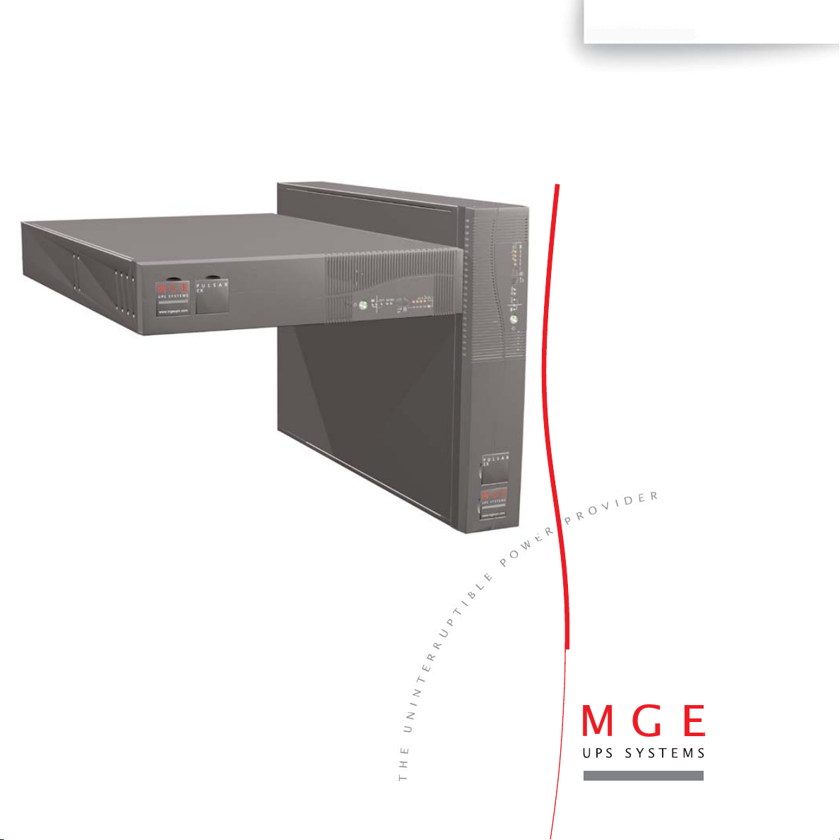
Pulsar EX
2200RT / 3200RT
EXB 2200/3200 RT
Installation and User
Manual
MGE UPS SYSTEMS,INC.
Page 2

SAVE THESE INSTRUCTIONS. This manual contains important instructions that should be followed during
installation and maintenance of the UPS and batteries.
Thank you for selecting an MGE UPS SYSTEMS, Inc. product to protect your electrical equipment.
The Pulsar EX RT range has been designed with the utmost care.
We recommend that you take the time to read this manual to take full advantage of your UPS’s many fratures.
MGE UPS SYSTEMS, Inc. pays great attention to the environmental impact of its products.
Measures that have made Pulsar EX RT a reference in environmental protection include:
◗ The eco-design approach used in product development,
◗ Recycling of Pulsar EX RT at the end of its service life.
To discover the entire range of MGE UPS SYSTEMS, Inc. products and the options available for the Pulsar EX RT range,
we invite you to visit our web site at www.mgeups.com or contact your MGE UPS SYSTEMS, Inc. representative.
This manual contains important instructions for Pulsar EX RT Models that must be followed during installation, operation
and maintenance of the UPS and batteries.
The Pulsar EX RT Models that are covered in this manual are listed below.
Pulsar EX 2200RT, Pulsar EX 3200RT.
The normal battery voltage for all models is as follows:
Pulsar EXB 2200/3200 RT: 72 Vdc.
The Pulsar UPS is intended for installation in a temperature within 0 to 40º C, free of conductive contaminant.
This equipment has been tested and found to comply with the limits for a Class A digital device, pursuant to Part 15 of the
FCC Rules. These limits are designed to provide reasonable protection against harmful interference when the equipment is
operated in a commercial environment. This equipment generates, uses, and can radiate radio frequency energy and, if not
installed and used in accordance with the instruction manual, may cause harmful interference to radio communications.
Operation of this equipment in a residential area is likely to cause harmful interference in which case the user will be required
to correct the interference at his own expense.
Important safety instructions
Read before installing product
Introduction
Page 2 - 3400753300/AE
Page 3

3400753300/AE - Page 3
CAUTION: Safety of persons
◗
The UPS has its own internal power source (the battery). Consequently, the power outlets may be energized even if the UPS
is disconnected from the AC-power source.
◗
Dangerous voltage levels are present within the UPS. It should be opened exclusively by qualified service personnel.
◗
The UPS must be properly earthed. Measurements are required to ensure that the total leakage current of the UPS and the
protected equipment does not exceed 3.5 mA by checking their characteristics (maximum leakage current of the UPS = 2 mA).
◗
The battery supplied with the UPS contains small amounts of toxic materials. To avoid accidents, the directives listed below
must be observed:
- Never burn the battery (risk of explosion).
- Do not attempt to open the battery (the electrolyte is dangerous for the eyes and skin).
-Comply with all applicable regulations for the disposal of the battery.
- Batteries constitute a danger (electrical shock, burns). The short-circuit current may be very high. Precautions must be
taken for all handling: remove watches, rings, bracelets and any other metal objects, use tools with insulated handles.
-Do not lay tools or metal parts on top of batteries.
CAUTION: Product Safety
◗
The UPS connection instructions and operation described in the manual must be followed in the indicated order.
◗
UPS must be connected to a nearby wall outlet that is easily accessible. The UPS can be disconnected from the AC-power
source by removing the power cord.
◗
Check that the indications on the rating plate correspond to your AC-power system and to the actual electrical consumption of
all the equipment to be connected to the UPS.
◗
Never install the UPS near liquids or in an excessively damp environment.
◗
Never let a foreign body penetrate inside the UPS.
◗
Never block the ventilation grates of the UPS.
◗
Never expose the UPS to direct sunlight or source of heat.
◗
If the UPS must be stored prior to installation, storage must be in a dry place.
◗
The admissible storage temperature range is -25ºC to +55ºC.
Special Precautions
◗
All handling operations will require at least two people (unpacking, installation in rack system).
◗
Once installed and connected to the AC power source for the first time, the battery will start to charge. Full charging to obtain
the rated battery backup time requires at least 8 hours.
◗
Before and after the installation, if the UPS remains de-energized for a long period, the UPS must be energized for a period of
24 hours, at least once every 6 months (for a normal storage temperature less than 25°C). This charges the battery, thus
avoiding possible irreversible damage. During the replacement of the battery module, it is imperative to use the same type and
number of element previously mounted in the UPS, in order to maintain an identical level of performance and safety. In case of
doubt, don’t hesitate to contact our after sales department (for more information, refer to the web site www.mgeups.com).
Introduction
Page 4
Page 4 - 3400753300/AE
Using this document
How to use this document
Icon Usage
Information may be found primarily by consulting:
◗ The contents,
◗ The index.
In the illustrations on the following pages, the symbols below are used:
LED off.
LED on.
LED flashing.
Audio indication.
Action.
Visual indication.
Notes, tips and information, help.
CAUTION: Hazard to personnel or equipment, information that must always be followed.
WARNING: Eminent hazard to personnel or equipment, information must always be followed.
Important information, help.
Page 5

3400753300/AE - Page 5
1. Presentation
1.1 System configurations ................................................................................................................7
Rack setup ......................................................................................................................................7
Tower setup ....................................................................................................................................7
1.2 Rear panel ......................................................................................................................................8
Pulsar EX 2200RT ........................................................................................................................8
Pulsar EX 3200RT ........................................................................................................................8
Pulsar EXB 2200/3200 RT ............................................................................................................8
1.3 Control panel ................................................................................................................................9
2. Installation
2.1 Unpacking ....................................................................................................................................10
2.2 Installation in rack position ........................................................................................................11
2.3 Installation in tower position ....................................................................................................12
2.4 Connection to the RS232 or USB communication port (optional) ........................................13
2.5 Installation of the communication-card option ........................................................................13
2.6 Connections ................................................................................................................................14
3. Operation
3.1 Start-up ........................................................................................................................................15
3.2 LED indicators ............................................................................................................................15
3.3 Operation on battery power (following failure of AC input power) ............................................16
Transfer to battery power ..............................................................................................................16
Threshold for the low-battery warning............................................................................................16
End of backup time ........................................................................................................................16
3.4 Personalization (optional) ............................................................................................................17
Function..........................................................................................................................................17
"ON / OFF conditions" tab..............................................................................................................17
"Battery" tab ..................................................................................................................................17
"Output" tab....................................................................................................................................18
"Bypass" tab ..................................................................................................................................18
3.5 UPS Shutdown ............................................................................................................................18
3.6 UPS Remote Power Off ..............................................................................................................19
Contents
Page 6

Page 6 - 3400753300/AE
4. Maintenance
4.1 Troubleshooting ..........................................................................................................................20
4.2 Replacement of the battery modules ........................................................................................22
5. Environment ....................................................................................................................................24
6. Appendices
6.1 Technical characteristics ..........................................................................................................25
6.2 Glossary ......................................................................................................................................26
6.3 Index ............................................................................................................................................27
Contents
Page 7

3400753300/AE - Page 7
Tower setup
Rack setup
1.1 System configurations
1. Presentation
Model Part Weight
Number (Ibs/kg)
Pulsar EX 2200RT 85220 80.8 lbs (36.6 kg)
Pulsar EX 3200RT 85320 82.7 lbs (37.5 kg)
Pulsar EXB 2200/3200 RT 85000 92.8 Ibs (42.0 kg)
17.24 inches (19" Rack mount)
25.75 inches (EX 2200RT)
26.00 inches (EX 3200RT)
3.75 inches
P U L S A R
E X
m
co
.
s
p
u
e
g
m
.
w
w
w
1
S
S
A
P
2
Y
B
0
1
%
0
%
8
%
0
5
%
0
t
2
s
e
t
(2U)
%
%
0
%
%
0
0
1
%
0
8
%
0
5
%
0
2
%
t
s
e
t
1
2
S
S
A
P
Y
B
A R
S
L
U
P
E X
m
o
c
.
s
p
u
e
g
m
w.
w
w
Page 8
Page 8 - 3400753300/AE
4
612111098
7
1
3
2
4
12111098
7
5
3
2
1
1514
15
14
13
12
Pulsar EXB 2200/3200 RT
Pulsar EX 3200RT
Pulsar EX 2200RT
11
10
8
9
7
6
5
4
3
2
1
Slot for communication-card option.
RS232 communication port.
USB communication port.
Upper two receptacles for connection
to AC-power source.
Lower two programmable receptacles
(1 and 2).
Output circuit breakers. (EX 3200RT)
Input/Output power cords for direct
connection of protected equipment.
EX 2200RT-L5-20P/L5-20R; and
EX 3200RT-L5-30P/L5-30R.
Connector for an additional battery
module.
Connector for automatic detection of an
additional battery module.
Pushbutton to test phase/neutral
inversion of AC-power source.
LED indicating Site Wiring Alarm
Enable, with flashing and intermittent
buzzer. Reset fault with rear panel
button.
Connector for remote power off (RPO).
Battery module connectors (to the UPS
or to other battery modules).
Connectors for automatic detection of
additional battery modules.
Circuit breaker for battery ON/OFF and
protection.
1.2 Rear panel
1. Presentation
5
13
13
L5-20P Plug
INPUT CABLE
L5-30P (Plug)
INPUT CABLE
L5-20R Receptacle
OUTPUT CABLE
L5-30R (Receptacle)
OUTPUT CABLE
Page 9
3400753300/AE - Page 9
27
2625
2423222120191817
16
(*) : ◗ flashing LED + buzzer: battery fault (battery must be replaced).
◗ flashing LED + long buzzer (once per hour): theoretical end of battery life (replacement recommended).
UPS
overload
Electronics
fault
Battery
fault *
Site Wiring
Fault
26
27
%
load
100%
80%
50%
20%
Press simultaneously at
least 3 seconds to reset
the “End of battery life”
alarm.
24
25
23
22
21
20
19
18
17
16
Status change in
progress.
Supplied with power
Operation on battery power.
Status of programmable outlet 2:
Operation in ON-LINE mode (backup power available).
Operation on bypass (no backup power available).
Status of programmable outlet 1:
1. Presentation
%
battery
remaining
100%
80%
50%
20%
ON / OFF.
◗ Lamp test or buzzer OFF.
◗ Forced transfer to bypass and back
by pressing button 3 times in less
than 5 seconds.
Hold down to display
percent load:
Alarms
1.3 Control panel
100%
80%
50%
20%
test
%
1
2
%
BYPASS
Page 10

Page 10 - 3400753300/AE
34
34
36
35
36
35
30
32
31
30
32
31
RS232 communication cable.
USB communication cable.
Telescopic rails for mounting in 19" bay with mounting hardware.
CD-ROM with the Solution-Pac and UPS Driver software.
Product documentation.
Two supports for the upright position.
2.1 Unpacking
2. Installation
%
%
0
0
1
%
0
8
%
0
5
%
0
2
%
t
s
e
t
1
2
S
S
A
P
Y
B
R
L S A
U
EX
P
www.mgeups.com
Page 11

3400753300/AE - Page 11
3
3
7
Stop-Notch
Snap from
inside of rails
2
6
4
5
5
2
1
CAUTION: Do not lean or place objects on top of unit at any time. Hazard of dismounting and disconnection can
occur with units.
NOTE: (For step 5) it is possible to adjust the position of the front fixing bracket.
Follow steps A to D for rack mounting of the UPS on the rails. The rails and the necessary mounting hardware are supplied in
the box along with the UPS (see item 32 on page 10).
2. Installation
2.2 Installation in rack position
A. Secure Rails together with three screws (1).
B. Attach frontal Rails to Rack front (2).
C. Attach rearmost Rails to Rack rear (3).
If using Stop-Notch (7) snap into rear rail.
(refer to Quick Start for positioning details.)
D. Attach both front brackets (4 & 5) to each
side of UPS, and slide (mount) UPS into
the Rack (6).
Page 12

Page 12 - 3400753300/AE
Install the two supports for the upright position using provided hardware in the package.
(see item 32 on page 10).
Pull out the MGE Logo and Model plates, then rotate them as shown.
2. Installation
2.3 Installation in tower position
%
%
0
0
1
%
0
8
%
0
5
%
0
2
%
t
s
e
t
1
2
S
S
A
P
Y
B
A R
L S
U
P
E X
m
o
c
.
ps
geu
.m
w
w
w
R
U L S A
P
www.mge ups.com
Page 13

3400753300/AE - Page 13
1
Slot for the
communication
card option.
It is not necessary to shut down the UPS to
install the communication card:
1.Remove the slot 1 cover secured by
two screws.
2.Insert the card in the slot.
3.Secure the card with the two screws.
2.5 Installation of the communication-card option
NOTE: The RS232 and USB communication ports cannot operate simultaneously.
31
30
1. Connect the RS232 30 or USB 31
communication cable to the serial port or
the USB port on the computer.
2. Connect the other end of the communication cable 30 or 31 to the RS232 2
or USB 3 communication port on the
UPS.
The UPS can now communicate with all
MGE UPS SYSTEMS, Inc. supervision,
set-up or safety software.
2.4 Connection to the RS232 or USB communication port (optional)
2. Installation
3
2
OUTPUT CABLE
L5-30P Plug
INPUT CABLE
L5-30R Receptacle
Page 14

Page 14 - 3400753300/AE
5
4
4
7
1. Connect the input power cord 7 to the
AC-power wall-receptacle.
2. Connect the protected equipment to the
UPS. It is advised to connect priority
loads to the outlets and/or power cord 4
and any non-priority loads to the two
programmable outlets 5 (If the UPS is
connected to a computer running MGE
UPS SYSTEMS, Inc. communication
software, it is possible to program the
interruption of power to the two
programmable outlets 5 during
operation on battery power, thus reserving backup power for the priority loads).
The battery begins charging the
instant the UPS unit is connected
to a power source. Eight hours are
required to charge to the full rated
backup time.
CAUTION: Check that the indications on the rating plate (on the back of the UPS), correspond to your AC-power
system, and to the actual electrical consumption of all the equipment to be connected to the UPS.
2.6 Connections
2. Installation
5-20P
Page 15

3400753300/AE - Page 15
2726
25
1817
16
24
201921 22 23 272625
18
1716
Description of LED indicator status 20 and 21 for programmable outlets 1 and 2:
◗ OFF: the outlets are not supplied with power.
◗ Flashing: status change in progress.
◗ ON: the outlets are supplied with power.
Outlets 1 and 2 can be remotely programmed and controlled.
They may be used for sequential start-up of the protected applications, shedding of non-priority applications during
operation on battery power, and priority management at the end of battery backup time to reserve the longest possible
backup time for the most sensitive applications. These outlets are programmed using Solution Pac software.
LEDs 24 to 27 provide three
different indications:
1. Remaining backup time in percent
(during normal operation).
2. Percent load drawn by the protected
equipment, when button 23 is pressed.
3. Operating faults (flashing LED and
beeps):
27 Overload.
26 UPS fault.
25 Battery fault or end of life warning.
24 Site wiring Fault
3.2 LED indicators
CAUTION:The AC input power source must be present when
energizing for the first time.
1. Press the ON / OFF button 16 .
◗ The buzzer beeps and all the LEDs go ON.
◗ The buzzer beeps twice, then:
◗ If AC input power is available, LED 18 goes ON, indicating
operation in ON-LINE mode.
◗ If AC input power is not available and the UPS is configured for
automatic restart mode, the buzzer beeps three times and LED 17
goes ON, signalling operation on battery power.
All connected equipment is energized.
NOTE: If LEDs 17 or 18 do not turn ON or if LEDs 25 to 27 flash,
there is a fault (see section 4.1).
3.1 Start-up
3. Operation
The protected equipment connected to the UPS can be energized, whether AC input power is available or not.
100%
80%
50%
20%
test
%
1
2
%
BYPASS
1
S
S
A
P
2
Y
B
e
t
%
%
0
0
1
%
0
%
8
%
0
5
%
0
t
2
s
Page 16

Page 16 - 3400753300/AE
22
17
17
The UPS goes to sleep mode at the end of the battery backup time, until complete shutdown, due to tripping of the
battery-protection function against deep discharge.
Return of AC input power:
IMPORTANT: If, in spite of the return of AC input power, the UPS does not restart, check that the automatic-restart
function (activated by return of AC input power) has not been disabled (see section 3.4).
The buzzer sounds continuously.
Press button 22 to turn the buzzer OFF.
The equipment is no longer supplied with power.
End of backup time
The low-battery warning threshold can be set by the user, with the UPS
Driver software (see section 3.4).
LED 17 flashes.
The buzzer beeps every three seconds.
There is very little remaining battery backup time. Close all
applications because UPS automatic shutdown is imminent.
Threshold for the low-battery warning
The AC-power source is outside tolerances, LED 17 is ON, the buzzer
beeps three times.
The equipment connected to the UPS is supplied by the battery.
Transfer to battery power
3.3 Operation on battery power (following an AC input power failure)
3. Operation
test
1
2
BYPASS
test
%
1
2
BYPASS
test
1
2
BYPASS
Page 17

3400753300/AE - Page 17
"ON / OFF conditions" tab
Options
Once a day
Once a month
No test
From 0% to 100% of the remaining
battery backup time
Disabled
Default setting
Every weeks
20% remaining
battery backup time
Enabled
Personalization function
Automatic "Battery test" intervals
"Low-battery warning" threshold
Protection against deep discharges
"Battery" tab
Personalization parameters can be set and modified using the UPS Driver software installed on a computer that is
connected to the UPS (see section 2.4 Connection to the RS232 communication port).
NOTE: Check that the RS232 30 cable is properly connected.
UPS Driver installation:
1. Insert the Solution-Pac CD-ROM containing the UPS Driver software into your computers CD ROM drive.
2. Open the file Manager and select the CD-ROM drive.
3. Launch "\Emb\Config\UPSDRVxx.exe" (xx = software version).
IMPORTANT: You can download the software UPS Driver from the www.mgeups.com as well, or contact an
MGE representative in your area. Once UPS Driver has been installed, the UPS parameters listed below can be
modified.
3.4 Personalization (optional)
Function
3. Operation
Options
Disabled
Disabled
Disabled
Enabled
Disabled
Default setting
Enabled
Enabled
Enabled
Disabled
Enabled
Personalization function
Automatic start
Cold start (battery power)
Forced shutdown
Sleep mode
UPS ON / OFF via software
Page 18

Page 18 - 3400753300/AE
16
Press button 16 (return to the OFF position).
The connected equipment is no longer supplied with power.
3.5 UPS shutdown
"Bypass" tab
"Output" tab
Options
Disabled (click to remove check)
Enabled (click to add check)
Default setting
Enabled
Disabled
Personalization function
Transfer to bypass if overload
Transfer to bypass following a fault, whatever the
conditions on the AC-power source
Options
100 V - 127 V
Converter
50 Hz
F ± 1% to ± 10%, in 1% steps
0 to 110%, in 10% steps
Enabled (click to add check)
Default setting
120 V
Autoselect
F = 60 Hz
F ± 5%
110%
Disabled
Personalization function
Rated UPS voltage
Frequency working mode
Rated UPS frequency
UPS tolerance for AC-power
source frequency
Overload alarm threshold
UPS restart following short-circuit
3. Operation
test
1
2
BYPASS
Page 19

3400753300/AE - Page 19
3837
12
1. Check that the UPS is shut off and disconnected from the AC power source.
2. Remove the RPO connector 12 by undoing the screws 37 .
3. Connect an insulated dry contact (NC, 60 V DC, 30 V AC max., 20 mA max., cable size 0.75 mm) to the two terminals
of the RPO connector 38 .
4. Put the RPO connector 12 back in place on the back of the UPS.
5. Connect the UPS to the AC-power source and restart it as indicated previously.
6. Activate the RPO external contact to test the function.
7. To return to normal operation, deactivate the RPO external contact and restart the UPS using button 16 (press OFF,
then ON).
Installation and test of the remote power off function
Pulsar EX RT's are equipped with a Remote Power Off function (RPO) that can cut power to all the devices connected to
the UPS using a remote user-operated contact.
The function is implemented by opening a contact connected to the two terminals of connector 12 on the back of the
UPS.
3.6 UPS Remote Power Off (RPO)
3. Operation
Page 20

Indication Diagnostic Correction
LED 27 flashes and UPS overload. Overload is too long or too high.
◗ Check the power drawn by the
the buzzer beeps.
◗ If AC power is present and within tolerances, the equipment and disconnect any
UPS goes to bypass mode (supply directly by the non-priority devices.
AC-power source). LED 19 flashes.
The buzzer beeps every second.
◗ If AC power is not present or not within tolerances,
the connected applications are no longer supplied.
The buzzer sounds continuously.
LED 25 flashes and A battery fault was detected during the ◗ Check that the battery connector
the buzzer beeps. automatic battery test. is fully pushed in.
◗ Replace battery module (see Maintenance section).
LED 25 flashes and The battery has reached the theoretical end ◗ Reset the alarm by pressing
the buzzer emits a of its service life. buttons 22 and 23
long beep once simultaneously for 3 seconds.
per hour.
◗ It is advised to replace both batteries at
See the section on maintenance. the same time with the same rating
as the original batteries.
The yellow LED 24 The function for monitoring the phase and neutral ◗ Directly earthed neutral type
flashes, the red position of your electrical network has detected a networks: check the cabling
indicator light 11 reversal. of phase and neutral on your
behind the UPS electrical network.
comes on and the For all other network types,
buzzer sounds de-activate the detection function
continuously. (this function is only operational
for directly earthed neutral electrical
networks):
Press for at least 5 seconds the
pushbutton 10 behind the UPS
(UPS stopped and connected to the
network for less than 30 minutes).
Page 20 - 3400753300/AE
If any of LEDs 25 , 26 or 27 flash, there is a operating anomaly or an alarm.
NOTE: If a LED flashes, the bargraph data is no longer displayed.
4.1 Troubleshooting
4. Maintenance
Page 21

3400753300/AE - Page 21
Indication Signification Correction
The outlets are not supplied One of the protection circuit breakers 6 for the
◗ Check that there is not a short-
with power, even though outlets (on the back of the UPS) is open. circuit on the outlets.
button 16 is ON
◗ Eliminate any overloads on the
(3200 RT only). outlets by modifying the
distribution of devices on the
outlets.
LED 26 flashes and UPS electronics have detected a UPS fault. ◗ Restart the UPS.
the buzzer sounds Depending on the UPS personalization parameters
continuously. (see section 3.4).
There are two possibilities:
◗ The equipment connected to the UPS continues to ◗ Call the after-sales support
be supplied, but directly from the AC-power source department.
(via the automatic bypass (LED 19 ON).
◗ The connected equipment is no longer supplied.
The equipment connected to the UPS is no
longer protected.
4. Maintenance
Page 22

C
D
P
U
L
S
A
R
1
0
0%
8
0%
5
0%
2
0
%
t
e
st
%
1
2
%
B
Y
PA
SS
E X
B
A
w
w
w
.
m
ge
u
p
s.
c
o
m
P
U
L
S
A
R
1
0
0%
8
0
%50
%
2
0
%
t
es
t
%
1
2
%
B
Y
P
A
S
S
E X
Page 22 - 3400753300/AE
C - Remove the left part of the front panel.
D - Disconnect the connector.
A - Unclip the small plate with the MGE
UPS SYSTEMS, Inc. Logo on the
UPS front panel.
B - Remove the 2 screws.
Removal of the battery modules
CAUTION: Load will not be protected during this procedure!
Batteries constitute a danger (electrical shock, burns). The short-circuit current may be very high.
Precautions must be taken for all handling.
Safety Rules:
◗ Remove all watches, rings, bracelets and any other metal objects that may come into contact with the battery modules.
◗ Use tools with insulated handles.
4. Maintenance
4.2 Replacement of the battery modules
Page 23

3400753300/AE - Page 23
G - Remove the two battery modules and
proceed with replacement.
Reinstallation of the battery modules
To reinstall the battery modules perform this procedure in reverse order e.g., “G”, “F”, “E”.
◗ To maintain an identical level of performance and safety, use battery modules identical to that previously
mounted in the UPS.
◗ Press the two parts of the battery connector tightly together to ensure proper connection.
E - Remove the screws securing the
battery cover.
F - Remove the cover.
4. Maintenance
G
G
10
0%
8
0%
5
0
%
2
0
%
t
e
s
t
%
1
2
%
B
Y
PA
S
S
F
E
1
0
0
%
8
0
%
5
0
%
2
0
%
t
es
t
%
1
2
%
B
Y
P
A
S
S
Page 24

Page 24 - 3400753300/AE
This product has been designed to respect the environment:
It does not contain CFC's or HCFC's.
UPS recycling at the end of service life:
MGE UPS SYSTEMS, Inc. undertakes to recycle, by certified companies and in compliance with all applicable regulations,
all UPS products recovered at the end of their service life (contact your MGE UPS SYSTEMS, Inc. branch office).
Packing:
UPS packing materials must be recycled in compliance with all applicable regulations.
WARNING:
This product contains lead-acid batteries. Lead is a dangerous substance for the environment if it is not properly recycled
by specialized companies.
MGE Customer Care Center
Technical questions? If you encounter a problem while following the instructions in
this manual, we recommend that you
contact our Technical Support Group at 1 800 523-0142.
Or visit MGE UPS SYSTEMS, Inc. website at www.mgeups.com for complete technical support information, FAQ and
RMA forms for service.
5. Environment
?
Page 25

Output power rating
AC-input
◗ Voltage
◗ Frequency
◗ Power factor
Output specification
◗ Voltage
◗ Frequency
◗ Harmonic distortion
◗ Overload capability
Battery (sealed lead-acid,
maintenance free)
Environmental and safety
◗ Noise level
◗ Operating temperature
◗ Relative humidity
◗ Safety
◗ EMC
◗ Agency markings
< 50 dBA
0 to 40° C
20 to 90% (without condensation)
UL 1778 / cUL CSA 22.2 N°107.1
FCC 47 CFR Part 15, class A
UL, CSA
6 x 12 V - 9 Ah
6 x 12 V - 7 Ah
Single phase, 60 V / 70 V / 80 V to 142 V
(1)
50/60 Hz (auto-select)
≥ 0.95
Pulsar EX 3200RT
3200 VA / 2080 W
Pulsar EX 2200RT
2200 VA / 1540 W
3400753300/AE - Page 25
(1) Input voltage correspond to 33% / 66% / 100% of the nominal power rating.
(2) Adjustable from 100 V to 127 V using UPS Driver software.
(3) Frequency converter mode may be set using the UPS Driver software.
6.1 Technical characteristics
6. Appendices
Single phase, 120 V ± 3%
(2)
50/60 Hz ± 0.5%
(3)
< 4% on linear load, < 6% on non linear load
110% continuous, 130% 12s, > 130% 1.5s
Pulsar EXB
2200/3200 RT
72VDC - 18 Ah
Runtime @ full load
20min -40min -60min -80min
1EXB -2EXB -3EXB -4EXB
QUALITY
Designed, Manufactured and
marked under ISO 9001 quality system.
UL, CSA
FCC Class A
UL , cUL
AC INPUT
EMI FILTER EMI FILTER
SAFETY
RELAY
BATTERY
CHARGER
AC/DC PFC
CONVERTER
POWER
SUPPLY
BATTERY
DC/DC
PUSH PULL
DC/AC
INVERTER
BYPASS
RELAY
AC OUTPUT
Page 26

Page 26 - 3400753300/AE
Authorized voltage range for Upper and lower voltage thresholds within which the UPS can operate on the automatic
transfer to bypass if fault or bypass in the event of a UPS fault or overload.
overload
Automatic bypass Automatic switch controlled by the UPS, used to connect the equipment directly to the
AC-power source in the event of a UPS failure or an overload.
Automatic start following This function automatically starts the UPS when AC input power returns following
return of AC input power shutdown at the end of the battery backup time. It can be enabled or disabled.
Backup time Time that the connected equipment can operate on battery power.
Bargraph Device on the front panel indicating the percent remaining backup time or the percent
load.
Battery test Internal UPS test on battery status.
Dialog box A window in a computer program displayed for selection by the user of various options
and parameter settings.
Double conversion The power supplied to the connected equipment is completely regenerated by
continuous double conversion, i.e. the AC power from the AC-power source is rectified
(AC - DC), then converted back (DC - AC) to AC power.
Equipment Devices or systems connected to the UPS output.
Forced shutdown Ten-second interruption in the supply of power to the connected equipment following a
system shutdown, even if AC input power returns during the interruption period.
Percent load Ratio between the power drawn by the connected equipment and the total power that
the UPS can supply.
Personalization A number of UPS functions can be modified using the UPS Driver software to better
meet the user’s needs.
Programmable outlets Outlets that can be automatically shed during operation on battery power (a shedding
time delay may be programmed using Solution-Pac software.
Remote Power Off External dry contact can be used to stop the unit, during an emergency situation for
example. All power is removed from the load.
Start on battery power This function makes it possible to energize the connected equipment even when AC
input power is not available (operation exclusively on battery power).
UPS Uninterruptible Power Supply.
UPS ON / OFF via software It is possible to enable or disable use of UPS ON / OFF controls by the computer-
system protection software.
6.2 Glossary
6. Appendices
Page 27

3400753300/AE - Page 27
O
ON LINE mode..................................................................9
Overload ................................................................9-18-20
P
Personalization ..............................................................17
Battery ....................................................................17
By-pass ..................................................................18
On/Off conditions ....................................................17
Output......................................................................18
Programmable outlets ..............................................8-9-15
R
Remote power off............................................................19
S
Site Wiring Fault................................................................9
Sleep mode ....................................................................17
Automatic restart ................................................17-18
Start-up............................................................................15
T
Technical characteristics ................................................25
Transfer (forced) ..............................................................9
U
UPS Driver ....................................................................17
UPS fault ..........................................................9-15-20-21
UPS ON / OFF via software ..........................................17
UPS shutdown ................................................................18
W
Web site............................................................................2
Weight ..............................................................................7
A
Automatic bypass....................................................9-18-20
Automatic start ................................................................17
B
Bargraph ......................................................................9-15
Battery
End of backup time..................................................16
Fault......................................................................9-15
Low-battery warning ................................................17
Recycling ................................................................24
Replacement ......................................................22-23
Transfer to battery power ........................................16
Buttons ..........................................................................8-9
Buzzer ........................................................................15-16
Buzzer shutdown ..............................................................9
C
Connection
Additional battery module ........................................8
Communication card ..............................................13
RS 232 communication port....................................13
USB communication port ........................................13
Communication ............................................................8-13
D
Dimensions........................................................................7
E
Environment ................................................................2-24
F
Forced shutdown ............................................................17
L
Lamp test ..........................................................................9
LEDs..............................................................................8-9
6.3 Index
6. Appendices
Page 28

For service call:
1 800 523-0142
Internet: www.mgeups.com
T H E U N I N T E R R U P T I B L E P O W E R P R O V I D E R
3400753300-AE
1660 Scenic Avenue
Costa Mesa, CA 92626, USA
Main Number: 714 557-1636
MGE UPS SYSTEMS, INC.
UPS SYSTEMS
M
G
E
 Loading...