

Page 1

CleanWave
12÷280 kVA
Installation and user
manual
English
R
E
D
I
V
O
R
P
R
E
W
O
P
E
L
B
I
T
P
U
R
R
E
T
N
I
N
U
E
H
T
Page 2

INDEX
1. INTRODUCTION.....................................................................................................3
2. PRESENTATION ....................................................................................................3
2.1. General presentation................................................................................................................................ 3
2.2. Range......................................................................................................................................................... 5
2.3. Technical specifications...........................................................................................................................6
3. SAFETY ..................................................................................................................7
3.1. Integration in housing.............................................................................................................................. 7
3.2. Cooling......................................................................................................................................................7
3.3. Electrical connections .............................................................................................................................. 7
3.4. Access to the filter....................................................................................................................................7
4. ELECTRICAL ENGINEERING................................................................................8
4.1. Electrical schematic ................................................................................................................................. 8
4.2. Electrical protections............................................................................................................................... 8
4.3. Wiring ....................................................................................................................................................... 8
5. INSTALLATION AND STARTING ..........................................................................9
5.1. Handling.................................................................................................................................................... 9
5.2. Electrical connections ..............................................................................................................................9
5.3. Energising............................................................................................................................................... 10
6. MAINTENANCE....................................................................................................11
7. TROUBLESHOOTING..........................................................................................12
8. CONTACT.............................................................................................................12
MGE-UPS CleanWave - Installation and user manual Page 2/13
Version 2.1 - 21/04/05 - (JME)
Page 3

1. INTRODUCTION
The present document is a user manual for the zero-sequenced filters CleanWave.
It is intended to the persons responsible for the installation, the use and the maintenance of the filters.
Each of these aspects is detailed in a specific chapter here under.
2. PRESENTATION
2.1. GENERAL PRESENTATION
The CleanWave filter exists in 2 versions :
IP00 : Basic version to be integrated by the customer.
IP21 : "Turn-key" version integrated in its housing.
The IP00 version of the Cleanwave
1
3
2
5
Fig. 1
filter appears as follows:
4
7
6
8
9
3
4
Fig. 2
1 Lo element
2 Zo element
3 Upstream (mains) terminals (1 - 4 )
4 Downstream (load) terminals (5 - 8 )
5 Fixation for optional current transformer for upstream
and downstream neutral current measurements
6 Lifting rings
7 Earth terminal
8 Identification plate
9 Temperature switches terminals
MGE UPS SYSTEMS CleanWave - Installation and user manual Page 3/13
Version 2.1 - 21/04/05 - (JME)
Page 4
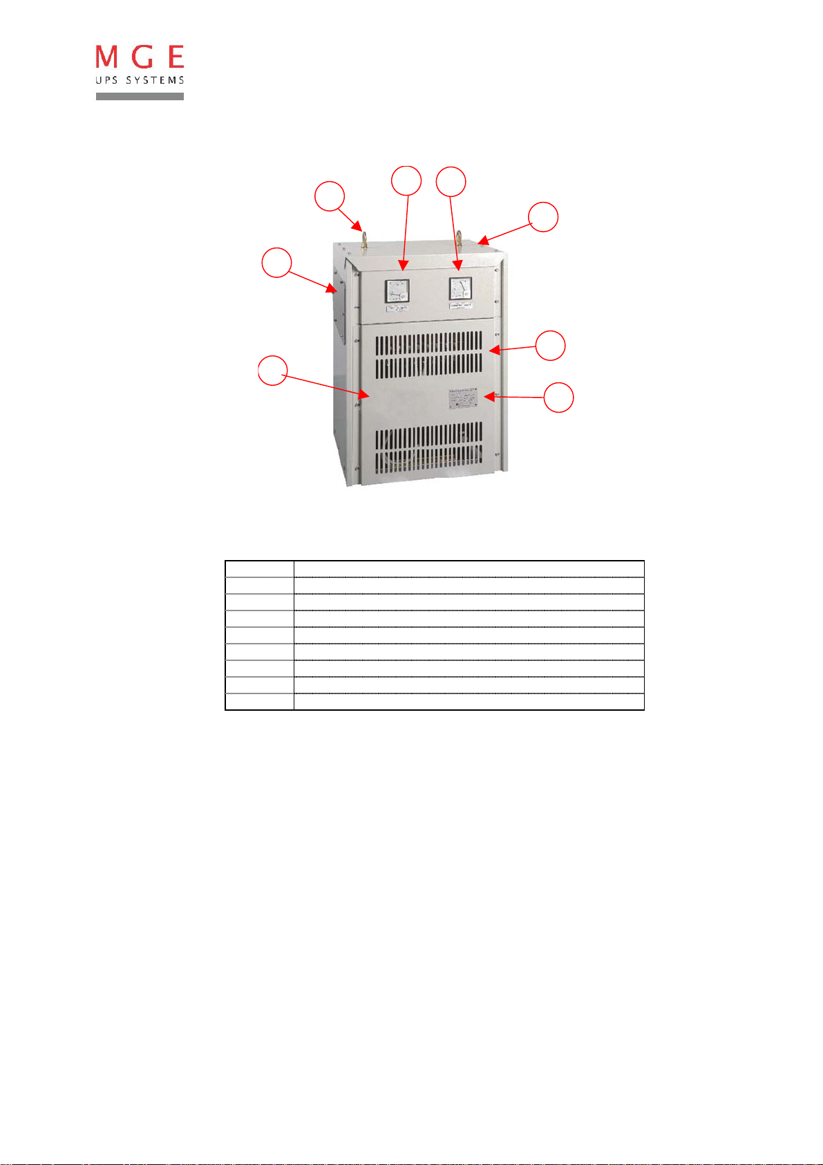
The IP21 version of the CleanWave filter appears as follows :
11
10
14
16
12
13
15
Fig. 3
10 Lifting rings
11 Upstream current display
12 Downstream current display
13 Removable top panel
14 Side panel for cabling
15 Ventilation grid
16 Removable front panel
17 Identification plate
17
Inside the housing, the filter is identical to the IP00 version shown on Fig. 1.
MGE UPS SYSTEMS CleanWave - Installation and user manual Page 4/13
Version 2.1 - 21/04/05 - (JME)
Page 5

2.2. RANGE
The following table summarises the characteristics of the different products of the range (at 400V,
50/60Hz).
I
TYPE Power.
[kVA] [A] [A] [W] [mm²] [mm²] [mm²] [mm²]
CleanWave-12 12 16 29 176 2.5 6 2.5 6
CleanWave-18 18 24 43 219 4 10 4 10
CleanWave-30 30 40 72 359 10 25 10 25
CleanWave-40 40 56 101 452 16 35 16 35
CleanWave-55 55 80 144 538 25 2x 25 16 2x 25
CleanWave-90 90 128 231 616 50 2x 50 25 2x 50
CleanWave-140 140 201 361 972 95 2x 95 50 2x 95
CleanWave-180 180 264 476 1212 150 2x 150 95 2x 150
CleanWave-220 220 321 577 1565 2x 95 2x 185 95 2x 185
CleanWave-280 280 401 722 1568 2x 95 2x 240 95 2x 240
phase
max
I
neutral
Max
Total
losses
max
Table 4
Phases Neutral (N) Earth (PE) ( PEN
Minimum sections
1
2
)
1
According to European standards
2
If common conductor for neutral and earth (PEN conductor)
MGE UPS SYSTEMS CleanWave - Installation and user manual Page 5/13
Version 2.1 - 21/04/05 - (JME)
Page 6

2.3. TECHNICAL SPECIFICATIONS
I
Standards
Construction and safety : IEC-60439-1
Conception : IEC-60289, IEC-60727
IP rating
Unprotected : IP00
Protected : IP21
Electrical specifications
Frequency : 50 / 60Hz
Nominal voltage between phases : 400V +15% / -10%
Reduction ratio
I
Ratio
Neutral
I
Phase
Inrush current : I
Neutralupstream
I
Neutral downstream
1:10
: 1.8
nominal
Overload capacity : 10% - 1 hour
25% - 10 minutes
50% - 2 minutes
Insulation class : 1.1 kV
Dielectric strength : 3 kV
Thermal class of insulation: H
Environmental conditions
Maximum ambient temperature : 50°C
Maximum altitude : 1000m
Maximum relative humidity : 90% without condensation
Please contact your MGE UPS SYSTEMS correspondent for different operating conditions.
www.mgeups.com
MGE UPS SYSTEMS CleanWave - Installation and user manual Page 6/13
Version 2.1 - 21/04/05 - (JME)
Page 7

3. SAFETY
CAUTION !!! The CleanWave® filter exhibits potentially lethal voltages.
Like any electrical equipment, the installation and the use of the CleanWave
precautions.
3.1. I
NTEGRATION IN HOUSING
The IP00 filters are intended to be integrated by the customer. They must be integrated by qualified
electricians in a housing or electrical cabinet guaranteeing the safety of the users according to
regulations, standards and rules of application in the corresponding country (Protection rating must
be at least IP20).
The IP21 version of the CleanWave
filter is already integrated in its housing and represents no
danger for people. It is forbidden to dismount the enclosure while the filter is energised.
3.2. C
OOLING
Though well the CleanWave filter has an excellent efficiency, its losses must be dissipated. The
maximum total losses in standard conditions are given in table 4.
In the case of the IP21 version, the integrator must ensure that the ventilation grids on the front
and rear sides of the filter are not obstructed. A minimum distance of 100mm must be free on both
sides of the housing. The ambient temperature should not exceed the maximum tolerated value
(as a standard, 50°C without de-rating).
®
require some basic
In the case of the IP00 version, it is the integrator 's responsibility to ensure a correct dissipation of
the losses given in table 4.
3.3. E
LECTRICAL CONNECTIONS
The cabling of the CleanWave® filter must be done with no voltage and by a qualified technician.
It is critical to respect the instructions given below as regards minimum wiring sections and
electrical protections. Some local regulations, particularities of the electrical installation or specific
rules may however impose the use of bigger sections.
The earth terminal of the filter must be properly connected to the earth of the installation, in respect
of the minimum recommended sections.
3.4. A
CCESS TO THE FILTER
The inside of the filter can only be accessed by qualified electricians and only with no voltage.
MGE UPS SYSTEMS CleanWave - Installation and user manual Page 7/13
Version 2.1 - 21/04/05 - (JME)
Page 8

4. ELECTRICAL ENGINEERING
The electrical study for the implementation of a CleanWave filter is very easy. The few instructions
described in this document must however be respected in order to ensure the safety and efficiency
of the system.
4.1. E
LECTRICAL SCHEMATIC
D1
L
0
Fig. 6
Z
0
CleanWave
a
Non
linear
load
In order to minimise the disturbing currents in the installation, the CleanWave® filter should be
placed close to the disturbing load.
4.2. E
LECTRICAL PROTECTIONS
The CleanWave filter must be protected in a similar way as a transformer.
As a standard rule, the electrical protection D1 must be a tetrapolar circuit breaker ( 3 phases +
neutral ) with neutral over-current detection.
If such a protection is not possible (e.g. when the neutral and earth connectors are common (PEN)),
a tripolar breaker will be used and the PEN conductor section will be doubled, as recommended
in table 4.
The breakers must be selected according to the phase current as given in table 4 here above. The
maximum inrush current is lower or equal to the nominal current and doesn't require particular
precautions.
4.3. W
IRING
The minimum recommended wiring sections for the different connectors are given in table 4. These
are minimum recommendations according to the European regulations. Higher sections may be
used according to local regulations, particularities of the electrical installation or specifi c rul es.
The neutral conductor may be crossed by a current up to 1.8 times the phase current and is
therefore over-sized.
MGE UPS SYSTEMS CleanWave - Installation and user manual Page 8/13
Version 2.1 - 21/04/05 - (JME)
Page 9

5. INSTALLATION AND STARTING
5.1. HANDLING
The filters are delivered on a wooden tray and can easily be moved with the help of a forklift.
They can also be handled with the help of the lifting rings.
5.2. E
LECTRICAL CONNECTIONS
The electrical connections must be done with no voltage by a qualified electrician.
To
mains
D1 Breaker
‘Upstream’
terminals
L1
L2
L3
N
Earth
PE
1
2
CleanWave
3
4
Fig.
7
6
7
8
5
‘Downstream’
terminals
L1
L2
L3
N
To
distorting
load
The power connections (see fig. 1 et 2) are done on the upstream (3) and downstream (4)
terminals.
For IP21 CleanWave
filters (see fig. 3), access to the terminals is possible either by removing,
without voltage, the top panel (13), or the lower part of the front panel (16). The cables can be
entered either from the bottom of the cabinet or through one of the side panels (17).
Fig. 8
MGE UPS SYSTEMS CleanWave - Installation and user manual Page 9/13
Version 2.1 - 21/04/05 - (JME)
Page 10

The connections are the following :
Terminal Connection
1 L1 upstream
2 L2 upstream
3 L3 upstream
4N upstream
5 N downstream
6 L1 downstream
7 L2 downstream
8 L3 downstream
Earth Earth (PE)
Table 9
The terminals must be properly tightened according to the size of the bolds.
Temperature switches are optionally foreseen on both the Lo and Zo elements for the detection of a
possible over-heating. In that case, for each element, two voltage-free contacts are available :
Terminals Connection
A1 - A2 Normally open contact ‘Warning’ (165°C)
D1 - D2 Normally closed contact ‘Alarm’ (190°C)
Table 10
These contacts are connected on two small terminal boards ( Fig. 2 - "9" ).
They are foreseen for a maximum current of 5A and a maximum voltage of 230V AC.
5.3. E
NERGISING
For obvious safety reasons, the energising of the filter can only happen once the housing is
perfectly secured.
During the energising of the filter, the loads downstream the CleanWave
®
filter will also be fed. It is
the technician's responsibility to check that the downstream installation can safely be
energised.
Once the filter energised, the displays on the front side (IP21 version only) should indicate some
upstream and downstream currents.
MGE UPS SYSTEMS CleanWave - Installation and user manual Page 10/13
Version 2.1 - 21/04/05 - (JME)
Page 11

6. MAINTENANCE
After installation, the CleanWave filter requires almost no maintenance.
We only recommend a periodic (e.g. annual) inspection.
This inspection must be done with no voltage by a qualified technician.
The working sequence is the following :
- Switch off the power of the CleanWave
- Open the housing in order to access the filter. In the case of the IP21 CleanWave
®
filter.
®
filter,
- Unscrew and remove the lower part of the front panel (see fig. 3 and 7).
- Check that there is no voltage on the terminals.
- Visually check the general aspect of the filter, especially that there is no excessive dust on
the Lo and Zo chokes.
- If necessary, clean the Lo and Zo with compressed air or with a vacuum-cleaner.
- Check the tightening of the power terminals.
- Close the housing.
- Power up the filter.
MGE UPS SYSTEMS CleanWave - Installation and user manual Page 11/13
Version 2.1 - 21/04/05 - (JME)
Page 12

7. TROUBLESHOOTING
Malfunction Solution
No neutral current is measured downstream
the filter.
No neutral current is measured upstream the
filter.
Tripping of the ‘Warning’ temperature sensor
of one of the chokes (Lo or Zo) (option).
Tripping of the "Alarm" temperature sensor of
one of the chokes (Lo or Zo) (option).
Is the filter energised ?
Is breaker D1 closed ?
Is the filter feeding the distorting load ?
The CleanWave® filter reduces the neutral current
by 10, approximately. It can happen that the
remaining value is too low and is not measurable.
Temperature of the element has reached 165°C
The load must be reduced in order to avoid
overheating of the filter.
Check that the phase and neutral currents respect
the limits given in table 4.
Check that the ventilation grids (front and rear) are
not obstructed.
Check that the Lo and Zo elements are not covered
with dust.
Isn't the ambient temperature excessive (standard :
50°C) ?
Temperature of the element has reached 190°C
Danger ! The filter must immediately be switched
off.
Table 11
If the observed malfunction is not in this list or if the problem remains after applying the recommended
solutions, please contact MGE UPS SYSTEMS to the address below.
8. CONTACT
For any assistance or complementary information, please contact your local distributor MGE UPS
SYSTEMS. You will find his details on the website www.mgeups.com .
MGE UPS SYSTEMS CleanWave - Installation and user manual Page 12/13
Version 2.1 - 21/04/05 - (JME)
Page 13

MGE UPS SYSTEMS T H E U N I N T E R R U P T I B L E P O W E R P R O V I D E R
140, Avenue Jean Kuntzmann
ZIRST - Montbonnot St Martin
38334 - Saint Ismier Cedex - France
www.mgeups.com
 Loading...