

Merrychef EC501, EC502 Parts List

Merrychef
Mealstream 500
SERVICE MANUAL
Part No. 32Z3387 Issue No.3
For all Mealstream 501, 502 & 503 models manufactured
from January 2001 & Tim Hortons Models
CAUTION MICROWAVE EMISSIONS
DO NOT BECOME EXPOSED TO EMISSIONS FROM THE MICROWAVE
GENERATOR OR PARTS CONDUCTING MICROWAVE ENERGY
SERVICE MANUAL
Page 1 Mealstream Ovens 32Z3387 Issue 3

Table of Contents
Safety Code...........................................................................3
Product Specifications...........................................................4
Installation Instructions..........................................................5
Error Codes and Diagnostics.................................................6
Main Features........................................................................7
Electronic Controls ................................................................8
Manual Controls ....................................................................9
Power Output Testing to EN 60335-2-90 ............................10
Power Output Testing..........................................................11
Power Transformer Test......................................................11
High Voltage Capacitor Test................................................12
High Voltage Rectifier Test............... ... ... .............................12
Magnetron Test ...................................................................12
Principal components LHS..................................................13
Principal components RHS..................................................14
Principal components Top...................................................15
Principal components Cavity Roof and Door.......................16
Principal components Cavity...............................................17
Principal components ( not shown in main views ) .............18
Input wiring..........................................................................19
Interlock Operation..............................................................20
Electronic Control Panel Assembly .....................................21
Manual Controls Panel Assembly........................................22
Membrane Panel Circuit......................................................23
Complete Spare Part Listing.......................................... 24-25
Electrical Diagrams ....................................................... 26-27
Appendix 1: MenuKey Download Procedure..................... ..28
Appendix 2: Cleaning procedure...... ............................. 29-30
Appendix 3: PCB Connection Points............................. 31-33
Appendix 4: Transformer upgrade..................... ... ... ............34
Appendix 5 Hot air motor replacement......................... 35-39
Appendix 6: Temperature sensor replacement ...................40
Appendix 7: Fuse change FLM020 Type....................... 41-42
Appendix 8: Tim Hortons .............................................. 44-47
Appendix 9: Door interlock set-up procedure ................ 48-52
Manual corrections and modifications.................................53
Merrychef Limited,
Station Road West,
Ash Vale, Aldershot
Hampshire GU12 5XA
United Kingdom
Tel: +44 (0)1252 371000 Fax: +44 (0)1252 371007
Internet address: http://www.merrychef.com
E-mail: sales@merrychef.com or service@merrychef.com
Page 2 Mealstream Ovens 32Z3387 Issue 3

SAFETY CODE
This manual is designed to assist engineers who have been on a recognised product familiarisation
and training course run by Merrychef Limited. It has been prepared to offer technical guidance f or the
Merrychef Mealstream 501 range of Combination Microwave Ovens.
Please remember that it is wiser not to attempt a service task if you are unsure of being able to
complete it competently, quickly, and above all safely.
To avoid injury to yourself, and to protect the appliance from possible damage, please follow this
Safety Code when servicing these ovens.
Before attempting to repair the oven, check it for microwave leakage.
Check that the oven is not emitting microwaves, even when supposedly not in
operation.
Check that the oven is not operating continuously, whether the display indicates
cooking or not.
Always discharge the HT capacitors before working on the oven using a suitably
insulated 10 MΩ Resistor
Before removing the rear cover from the oven, ensure you do the following:
• Switch off the mains supply and remove the plug from the wall socket.
or
• If the oven is hard wired, ensure that the power is turned off at the isolator switch.
Note:
The On/Off switch on the oven is not adequate protection against electric
shock, as it does not isolate all of the internal wiring from the mains.
Upon completion of a service on a Mealstream oven, or before reconnecting the appliance to the
mains supply for testing, check all of the following points:
• All internal electrical connections are correct (see wiring diagram Pages 26-27).
• All wiring insulation is correct and is not touching a sharp edge.
• All Earth connections are electrically and mechanically secure.
• All door safety interlocks are secure and mechanically sound.
• The door operation is smooth, and the arms run freely in the slots.
• The door activates all three of the door interlock switches in the correct order.
• The temperature sensor is correctly connected to the Power PCB.
Before finishing the service call, recheck the following points:
• All of the electronics are functioning correctly, and all of the touch pads are working.
• The power output of the oven is correct.
• Microwave emission is below permissible limit - 5 mW/cm² (see BS EN 60335-2-90).
• Oven has correct 50mm air gap all round and 50mm above.
Air flow should not be restricted.
• Clean air filters are in place.
Page 3 Mealstream Ovens 32Z3387 Issue 3

Product specifications:
Model Number: CTMx v f c p MK C
Example CTM524505MK
Mealstream EC501, High speed fan
230-240V, 50Hz, Series 5 electronic controls & MenuKey
CTMx
Fan Speed
CTM3 =
Low speed
CTM5 =
High speed
Power
Requirements
Power Output:
CTM3
CTM5
External
Dimensions
Internal
Dimensions
v
Voltage
22 = 220-230V EU
24 = 230-240V UK
Refer to rating Plate
Microwave 100%
Convection
Combination
Convection
Combination
Height
Width
Depth
Height
Width
Depth
Capacity
f
Frequency c Control Type p Phase
50 = 50 Hz
60 = 60 Hz
5 = Electronic
CD2 = Rotary Dial
Controls
2 = 2 phase
1 = 1 phase
Omitted
1425W (IEC 705)
2500W
1425W + 2500W
3000W
1425W + 3000W
640mm (Plus 50mm minimum cleara nc e ab ove)
710mm (Plus 50mm minimum clearance each side)
630mm (Plus 50mm clearance behind)
260mm
490mm
360mm
45.86 litres (1.62 ft³)
MK
MenuKey
MK =
MenuKey
fitted
C
Catalytic
Converter
C=
EC503
Catalytic
Converter
Weight Nett
Gross packed
Construction Cavity
Casework
Settings Microwave
Temperature
Timer
90kg
106kg
304 Stainless Steel
100%,75%,50%,25%, Convection only
Off, 150°C, 175°C, 200°C, 225°C, 250°C
Up to 30 minutes
Up to 3 cooking stages of up to 30 minutes each
Programmed (Series 5)
Page 4 Mealstream Ovens 32Z3387 Issue 3
Installation instructions:
Installation Instructions for Mealstream 500 series Combination Ovens
Power Supply Requirements
The Mealstream 500 series oven should be connected to a suitable electricity supply, which
can cope with the switching-on surge that occurs with certain types of catering equipment, such
as microwaves. Because of this requirement, we strongly recommend that a separate, suitably
rated supply is installed for the oven.
The supply for the oven should be fitted with a Type "C" circuit breaker, rated at:
30 Amp for Mealstream 500 Series (all models)
If the oven is hard-wired to the supply, a double-pole isolator switch with a contact gap of at
least 3mm should be fitted and positioned close to the oven to allow the oven to be moved for
servicing.
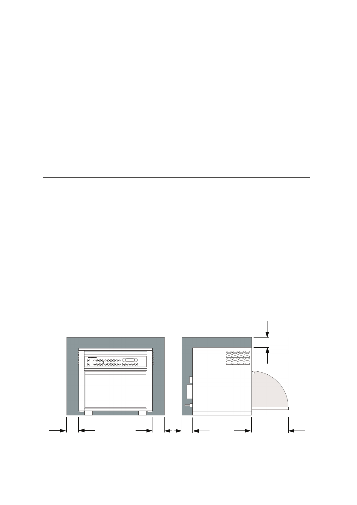
Positioning the Oven
In order to maintain adequate ventilation for air intake and exhaust, and to allow access for
cleaning filters, you must allow a minimum of 50mm clearance at the sides and rear of the
oven, and at least 50mm above. Air intake temperature should not exceed 35°C - excessive
temperature will lead to reduced operating duty cycle or premature ageing of internal
components.
Failure to comply with these conditions will invalidate the warranty.
NEVER Install an oven above fryers, grills, griddles or any other major heat source.
NEVER Stack machines on top of each other - always use a double stand.
ALWAYS Place containers in the cavity carefully - impact damage may chip the
vitreous enamel coating on the runners and baffle plate.
50mm 50mm
50mm
50mm
350mm
Page 5 Mealstream Ovens 32Z3387 Issue 3
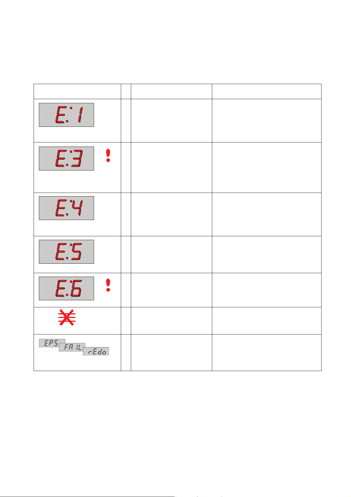
Error codes and diagnostics
Models with electronic controls identify some of the most common problems by flashing an
error message code in the time display window.
Error Message
1
1
1 Oven Cavity overheating Check cavity sensor
Possible Cause Service
Door not fully shut
2
Possible electrical fault
No time has been set
Invalid time has been set
2
Invalid program has been set
3
Number pad failure
4
Memory Failure running a
5
Program
Oven not heating up
1
Possible Heater circuit fault
2
Close door fully
Check Microswitch Door Circuit
Check Microswitch Connection to PCB
Check Ribbon Cable
Check Relay PCB & Logic PCB
Set a time
Set a valid time
Use call-back to check program
(MenuKey: no key downloaded)
Membrane key short circuit
Re-Program Pad,
if fault repeats replace Logic PCB
Check heater fuse
Confirm operation of heater, overheat
stat and heater circuit
Confirm heater relay is operating
1 Oven is not at correct
temperature to start program
Operator Error !!
1 Oven control area is
overheating.
MenuKey removed before the
download is complete
or the process has been
interrupted.
Allow oven to reach correct
Programmed temperature
Check air filters
Check axial fan
Check installation for hot air intake
Switch oven off and begin the MenuKey
download again.
Page 6 Mealstream Ovens 32Z3387 Issue 3
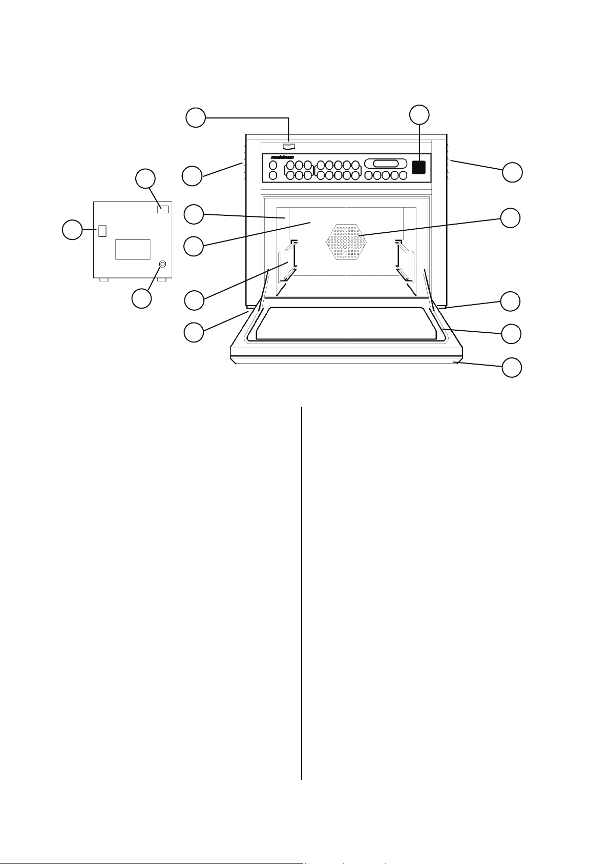
Main features:
m
g
j
back panel
a
b
c
d
e
k
l
b
f
k
i
h
a On/Off SWITCH
This is used to turn the oven On or Off.
IT DOES NOT IS OLATE INTERNAL WIRING
FROM THE MAINS SUPPLY.
b HOT AIR VENTS
Allows steam and excess pressure to escape
from the oven cavity. It must be kept clear.
c OVEN CAVITY
The oven cavity is mainly constructed from
stainless steel panels. It must be kept clean.
d BAFFLE PLATE
EC501 Models:
The convection fan draws air over the heating
element into the cavity ove r the edges of the rear
baffle plate producing perfect heat distribution for
combination cooking. The metal grill covering the
fan must be kept clean and free of debris.
502 & 503 Models:
The convection fan, which is located behind the
cavity filter pulls air in through the catalytic
converter which removes the majority of the smoke
from the air flow.
e RUNNERS
These are mounted on each side of the oven
cavity to support the rectangular racks or oven
trays and are for use in Convection mode
only.
f HOT AIR FAN
Situated behind the baffle plate, and circulates
the hot air through the baffle plate, over the
heating element, and around the edge of the
baffle plate back into the cavity.
CTM3_ Low speed Fan
CTM5_ High Speed Fan
g RATING PLATE
The rating plate is situated on the rear of the
oven, and states the Model, Serial Number,
Electrical Ratings and Manufacturers telephone
number.
h DOOR
The door consists of a thermally insulated inner
section, and an additional air gap provided by a
twin skinned door front to lower the surface
temperature.
It is important that the choke plate and the slots
are free from debris.
i DOOR SEAL
j MAINS LEAD
k AIR FILTERS
Main intake for cooling air for internal
components. Must be clear of obstructions.
l MenuKey
m STEAM OUTLET
Page 7 Mealstream Ovens 32Z3387 Issue 3
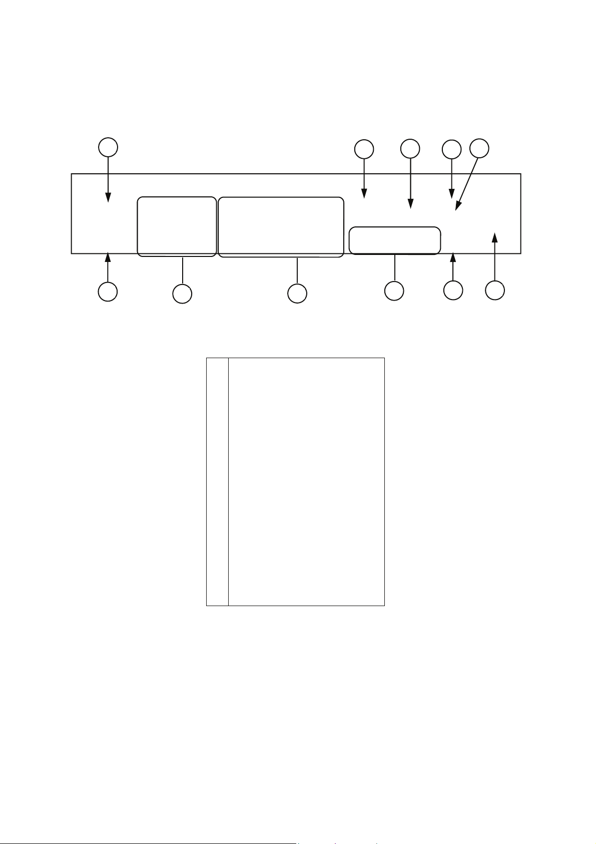
Electronic controls:
j
i
h
g
a
b
f
d
c
e
k
a Stage LED's
b Program & Time Display
c Service Indicator
d Air Filter Block Indicator
e Convection Pad
f Power Pads
g Time / Program Number Pads
h Temperature Set Pads
i Cancel / Callback Pad
j Program Pad
k MenuKey socket
Page 8 Mealstream Ovens 32Z3387 Issue 3
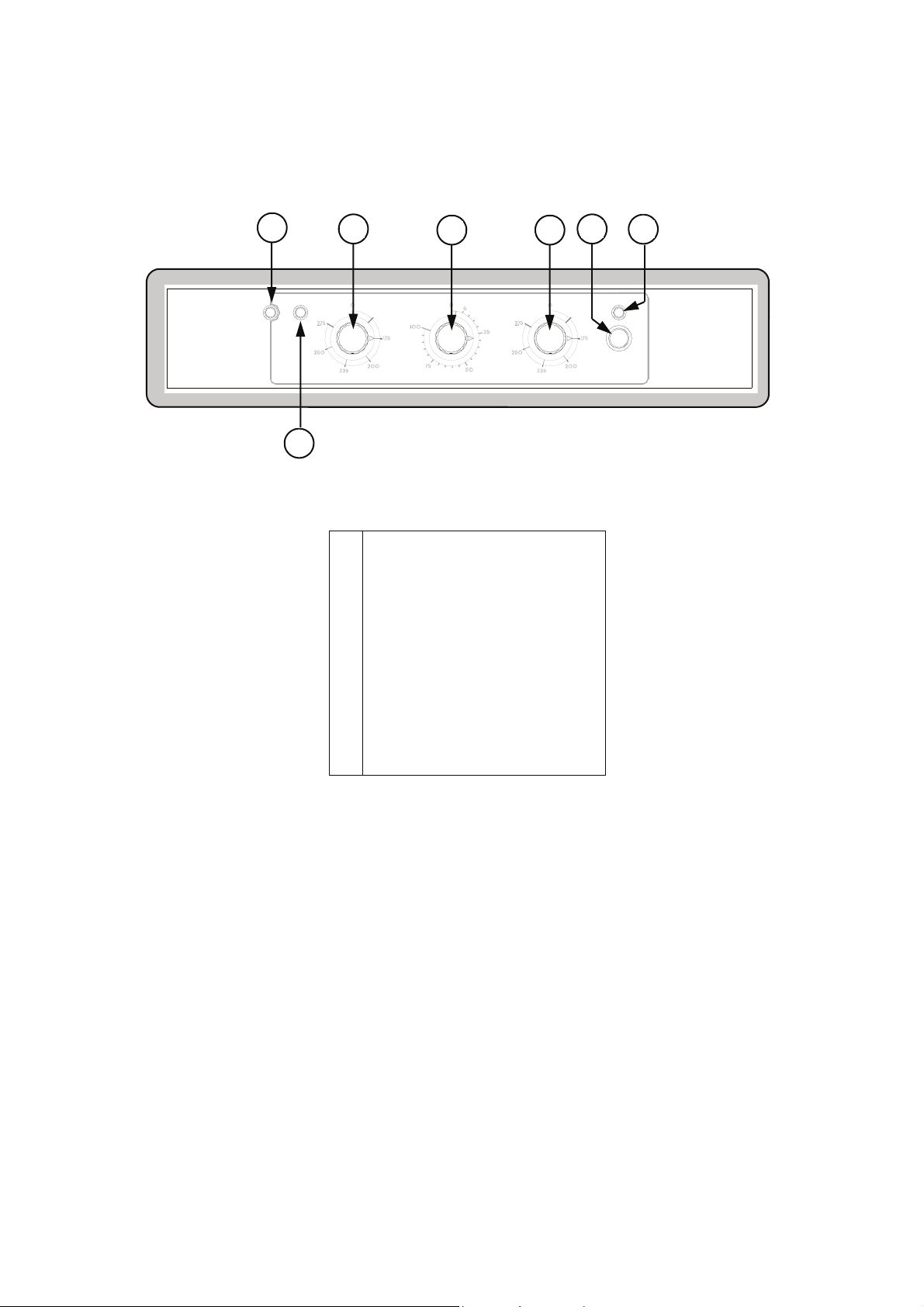
Manual controls:
merrychef
a
b
c d
POWER %TEMP °C
TIME
e
START
f
Mealstream CD
2
g
a Power Neon ( Amber )
b Temperature Control
c Power Control
d Timer
e Start Push button
f Cook cycle Neon ( Red )
g Heater Neon ( Amber )
Page 9 Mealstream Ovens 32Z3387 Issue 3

Procedure A - Power Output Test in accordance with
BS EN 60335-2-90 Annex AA
This test is given in the BSI test standard for microwave ovens. It is reproduced belo w - not so that
you can follow it, but to show you why it is impractical in normal conditions. A simplified procedure,
which gives a good approximation to the BSI power output, is given in Procedure B which follows.
Note: This test can only be carried out on a COLD oven. If the oven has been operating, even for
only a few seconds, the power given will be lower than the oven rating. This test must also be carried
out at a stable voltage - the voltage in most kitchens varies considerably even within the period of the
test. If the oven has been operating, go to Procedure B.
You will need:
A thermometer capable of reading to ±0.1°C.
A cylindrical borosilicate glass container, 190 mm diameter, with a wall thickness of
3 mm or less.
A calculator.
A set of scales capable of reading 1kg to an accuracy of ± 1g.
A glass or plastic stirrer.
A jug capable of holding over 1 litre of water.
Drinkable water which is at a temperature of 10°C ± 1°C.
A “Variac” or similar variable transformer capable of supplying the oven to ensure a
stable voltage.
WARNING: The Borosilicate Glass container has thin walls and is therefore fragile
- take care not to break it during use.
Method
A cylindrical container of borosilicate glass is used for the test. It has a maximum thickness of
3mm, an external diameter of approximately 190mm and a height of approximately 90mm. The
mass of the container is determined.
At the start of the test, the oven and the empty container are at ambient temperature. Potable water
having an initial temperature of 10°C ± 1°C is used for the test. The temperature of the water is
measured immediately before it is poured into the container.
A quantity of 1000g ± 5g of water is added to the container and its actual mass obtained. The
container is then immediately placed in the middle of the oven base. The appliance is supplied at
rated voltage and operated at the maximum power setting. The time for the water temperature to
attain 20°C ± 2°C is measured. The oven is then switched off and the final water temperature is
measured within 60seconds.
NOTES:
1 The water is stirred before its temperature is measured.
2 Stirring and measuring devices are to have a low heat capacity.
The microwave power output is calculat e d from the formula:
4.187 M
(T2-T1) + 0.55 MC (T2-T0)
W
P =
t
where
P is the microwave power output, in watts;
M
is the mass of the water, in grams;
W
M
is the mass of the container, in grams;
C
T
is the ambient temperature, in °C;
0
T
is the initial temperature of the water, in °C;
1
T
is the final temperature of the water, in °C;
2
t is the heating time in seconds, excluding the magnetron filament heat-up time.
Page 10 Mealstream Ovens 32Z3387 Issue 3
Procedure B - Simplified Power Output Test
You will need:
A thermometer capable of reading to ±0.1°C.
A Polypropylene tray approximately 200 mm x 200 mm.
A measuring jug.
A calculator.
Water which is at a temperature of 10°C ± 2°C.
1 Measure 1 litre of cold water into the tray using the measuring jug.
2 Measure the water temperature, and record it as T[s].
3 Place the tray in the oven and close the door.
4 Turn the oven on.
5 Set the timer to 1:02. ( For Manual controls use a stopwatch set to 1 minute 2 seconds )
6 Press the “100%” power pad.
7 When the oven bleeps, open the door and remove the tray.
8 Stir the water thoroughly, and measure its temperature. Record this as T[e].
Calculation:
1 T[r] = T[e] - T[s].
2 Power = 70 x T[r]. Power is in Watts.
The power given by the above test should be within ±10% of the rated power.
For Tim Hortons
see APPENDIX 8
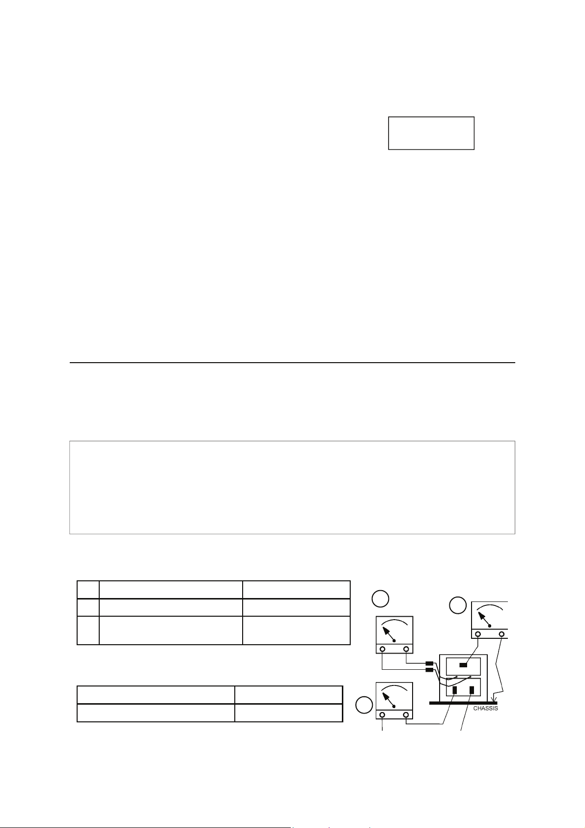
Procedure C - Power Transformer Test
You will need:
A Digital Multi-meter (D.M.M.)
A Megger or similar resistance meter using 500V d.c.
1 Isolate the oven from the mains supply.
WARNING: High voltages and large currents are present at the secondary winding and filament
winding of the Power Transformer. It is very dangerous to work near this part when the
oven is on. NEVER make any voltage measurements at the High Voltage circuits,
including the magnetron filament.
WARNING: Even when the oven is n ot cooking, the Power Transformer has High Voltages present
because of the Soft Start circuit. Isolate the oven before testing.
2 Ensure that the High Voltage Capacitor is discharged before commencing work.
3 Remove all connections from the Power Transformer.
4 Using a D.M.M., check the continuity of the windings. Results should be as follows:
a Mains winding between tags
b High Voltage winding
c Filament winding
between terminals
Approx. 1.3 Ω
Approx. 82 Ω
Less than 1 Ω
c
b
5 Using a Megger, test the insulation resistance between:
Primary winding and chassis
Filament winding and chassis
One end of the High Voltage winding is connected to the
chassis, so this is not tested.
Pass if over 10 MΩ
Pass if over 10 MΩ
a
Page 11 Mealstream Ovens 32Z3387 Issue 3
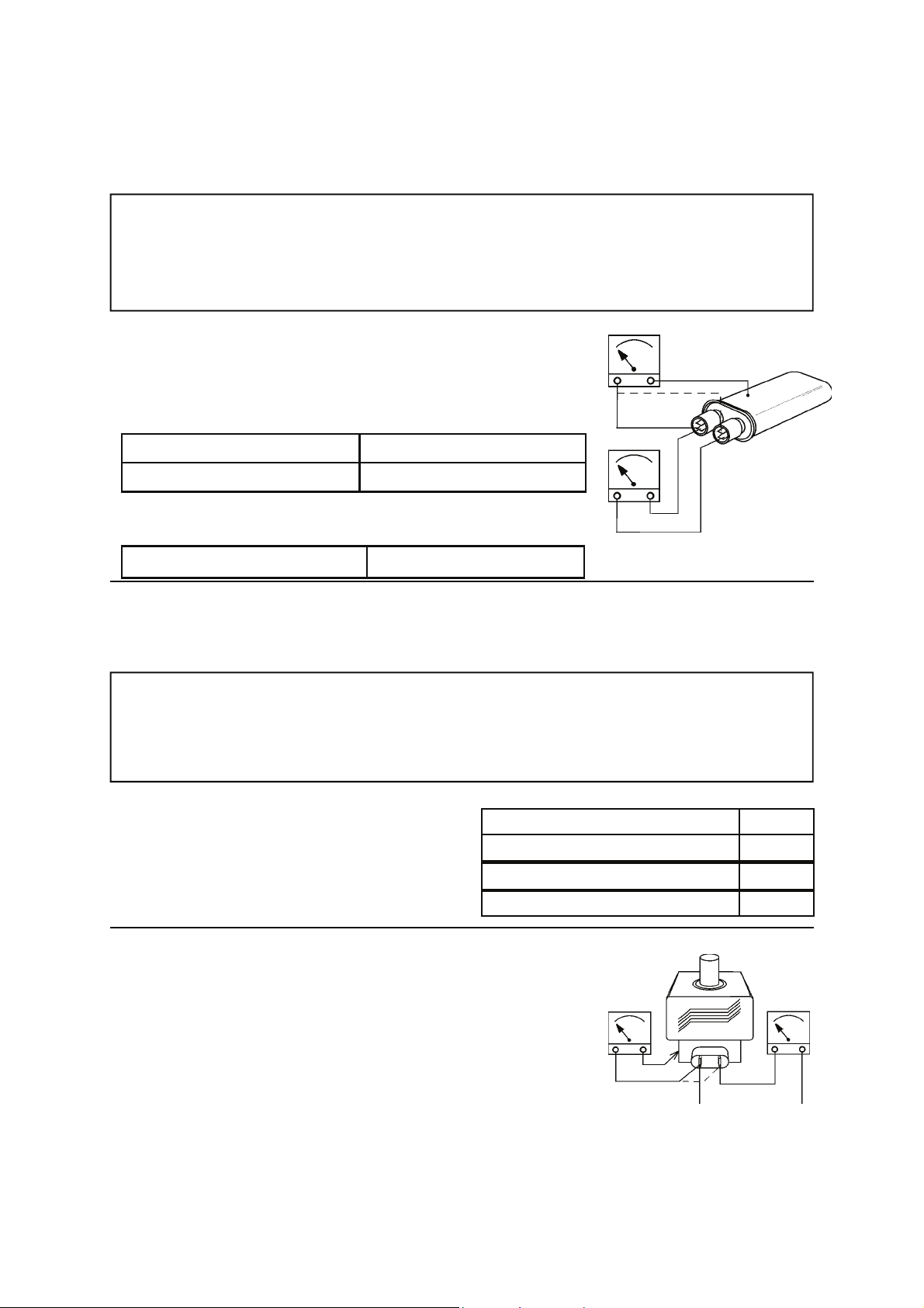
Procedure D - High Voltage Capacitor Test
You will need: A Digital Multi-meter (D.M.M.)
A Megger or similar resistance meter using 500V d.c.
WARNING: High voltages and large currents are present at the High Voltage Capacitor. It is very
dangerous to work near this part when the oven is on. NEVER make any voltage
measurements at the High Voltage circuits, including the magnetron filament .
WARNING: Even when the oven is not cooking, the High Voltage Capacitor has High Voltages
present because of the Soft Start circuit. Isolate the oven before testing.
1. Isolate the oven from the mains supply.
2. Ensure that the High Voltage Capacitor is discharged before
commencing work.
3. Remove all connections from the High Voltage Capacitor.
4. Using a D.M.M., check for continuity between the terminals &
Between Terminals
Between Terminals and Case Pass if open circuit
5. Using a Megger, test the insulation resistance between the
terminals and the case.
Between Terminals and Case
Procedure E - High Voltage Rectifier Test
You will need:
A Megger or similar resistance meter using 500V d.c.
WARNING: High voltages and large currents are present at the High Voltage Rectifier. It is very
dangerous to work near this part when the oven is on. NEVER make any voltage
WARNING: Even when the oven is not cooking, the High Voltage Rectifier has High Voltages
1. Isolate the oven from the mains supply.
2. Ensure that the High Voltage Capacitor is
discharged before commencing work.
3. Remove all connections from the High Voltage
Rectifier.
4. Using the Megger, test for continuity in both
directions. Compare results with the table.
measurements at the High Voltage circuits, including the magnetron filament .
present because of the Soft Start circuit. Isolate the oven before testing.
Pass if approximately 10 MΩ
Pass if over 100 MΩ
Open Circuit both ways
Conducts one way only
Short Circuit both ways
Conducts one way, leaks the other
FAIL
PASS
FAIL
FAIL
Procedure F - Magnetron Test
You will need:
A Megger or similar resistance meter using 500V d.c.
A Magnetron can be tested for an open filament or a short circuit
by carrying out a continuity check.
1. Isolate the oven from the mains supply.
2. Ensure that the High Voltage Capacitor is discharged before
commencing work.
3. Remove all connections from the Magnetron.
4. A continuity check across the Filament terminals should be 1ohm or less
5. A continuity check between each filament terminal and the
metal outer should read open.
Page 12 Mealstream Ovens 32Z3387 Issue 3
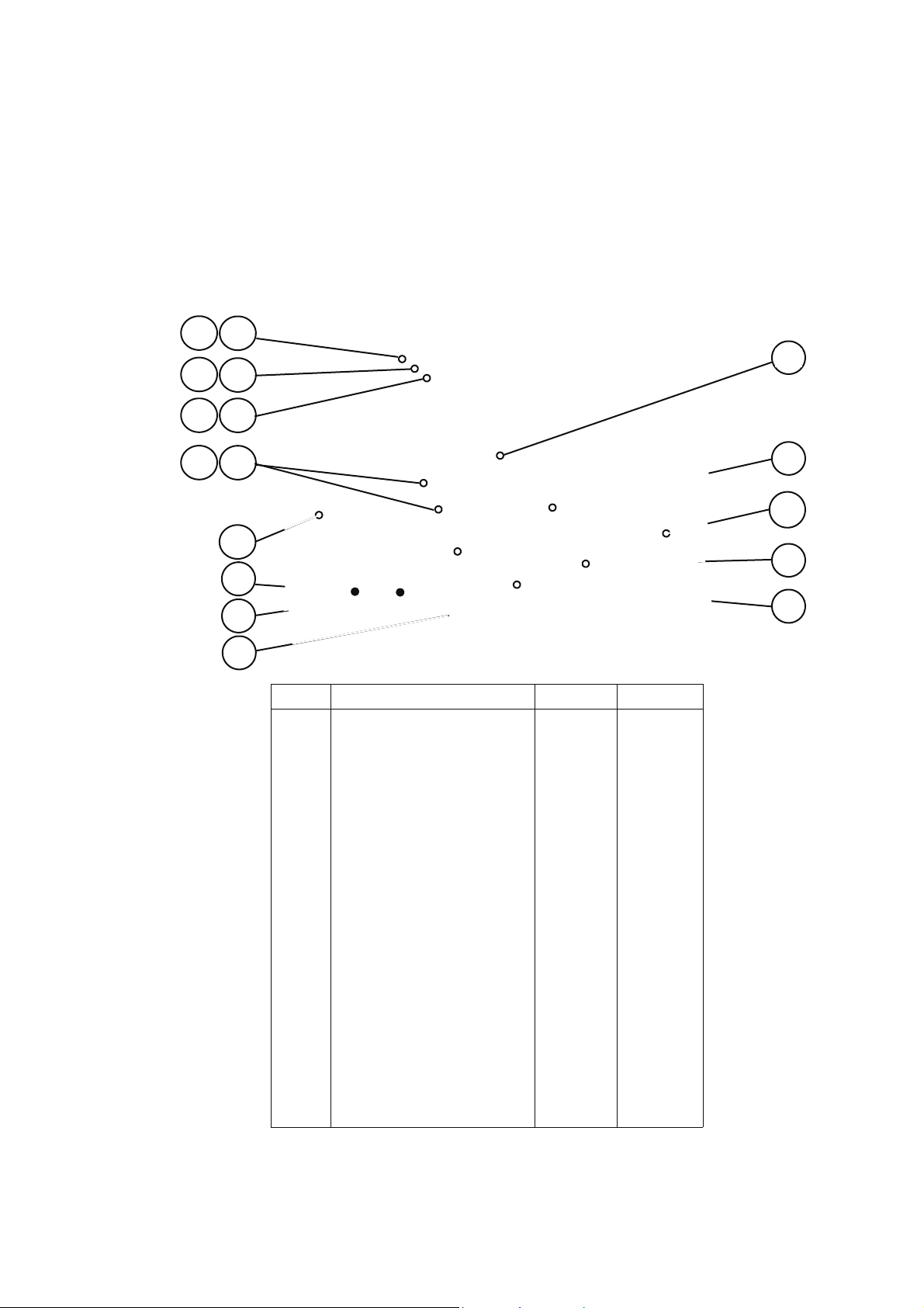
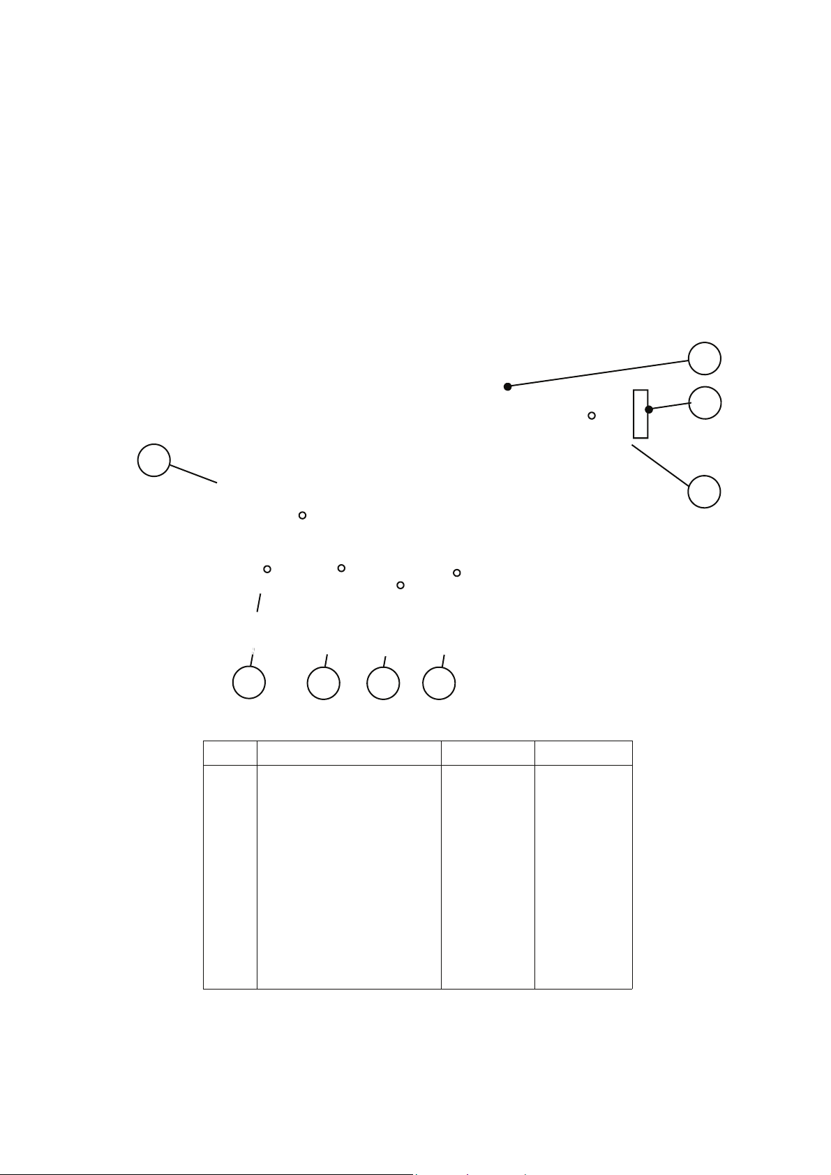
Principle components:
Left side
1
1A
2
2A
3
3A
14
4A 4
13
12
6
11
7
8
10
9
No Description EC 501/2/3 RD 501
1 Fuse holder 30Z0231 30Z0231
1A Fuse 10 amp 30Z0217 30Z0217
2 Fuse holder 30Z0231 30Z0231
2A Fuse 10 amp 30Z0217 30Z0217
3 Fuse holder 30Z0231 30Z0231
3A Fuse 1 amp 30Z0957 30Z0957
4 Fuse holder 30amp ( FLM Series )B 30Z1178 30Z1178
4A Fuse 20 amp Littlefuse FLM020B 30Z1177 30Z1177
6 Mains terminal block 31Z0149 31Z0149
7 Filter ( Heater circuit ) 30Z0997 30Z0997
8 Filter ( Microwave circuit ) 30Z0997 30Z0997
9 Door spring short 520000 520000
9 Door spring long 40C1141 40C1141
10 Door arm stop assembly 11C0279 11C0279
11 Microswitch ( Primary ) 30Z0240 30Z0240
12 Door hinge assembly ( LH )A 11C0167 11C0167
13 Door arm assembly 11C0300 11C0300
14 Microswitch ( Monitor ) 30Z0240 30Z0240
Note A: see page 17 for parts
Note B: see appendix for models before March 2004
Page 13 Mealstream Ovens 32Z3387 Issue 3
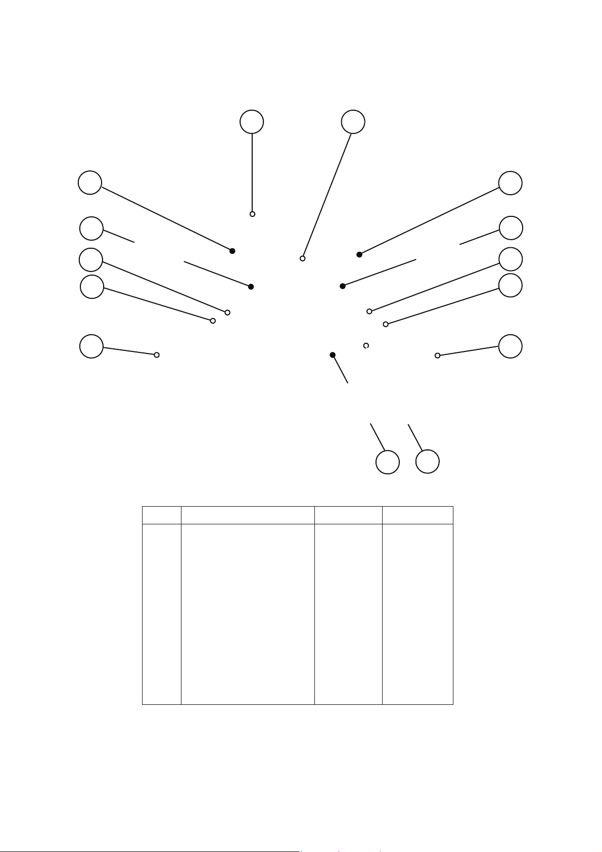
Principle components:
Right side
13
22
21
20
16
No Description EC 501/2/3 RD 501
9 Door spring short
9 Door spring long
10 Door arm stop assembly
13 Door arm assembly
16 Door hinge assembly ( RH )A
17 Microswitch ( Secondary )
20 Steam pipe
21 Steam vent guard
22 Temperature sensorC
Note A: see page 17 for parts
Note C: see appendix for models before March 2004
17
9 10
520000 520000
40C1141 40C1141
11C0279 11C0279
11C0300 11C0300
11C0166 11C0166
30Z0240 30Z0240
790046 790046
790061 790061
50E123 50E123
Page 14 Mealstream Ovens 32Z3387 Issue 3
Principle components:
Top view
23
24
25
26
27
60 61
23
24
25
26
27
28
No Description EC 501/2/3 RD 501
23 Magnetron 30Z0264 30Z0264
24 Resist or Gold 470 R 30Z0283 30Z0283
25 HT diode 11C0266 11C0266
26 Capacit or 1. 1µF 30Z1077 30Z1077
27 Trans f o rmer 220 V 50Hz 30Z0083 30Z0083
27 Trans f o rmer 240 V 50Hz 30Z1018 30Z1018
28 Twin blower motor 310110 310110
60 25mm OD Flexible conduit 314402 314402
61 20mm OD Flexible conduit 314401 314401
62 Capacitor c lip 31Z0175 31Z0175
62
Page 15 Mealstream Ovens 32Z3387 Issue 3
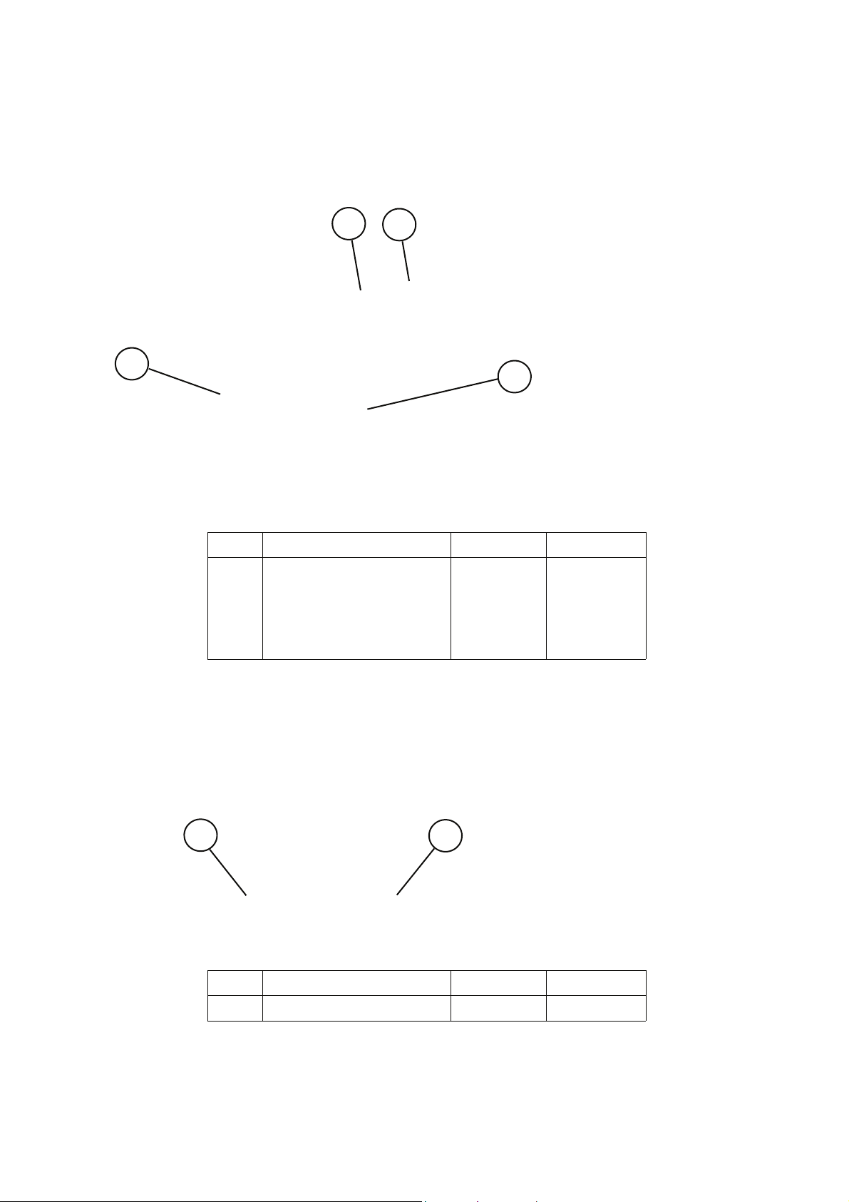
Principle components:
Door & cavity roof
72
67
67a
71
Note: for Tim Hortons see Appendix 8
No Description EC 501/2/3 RD 501
67 Stirrer glass & long seals 40C0954 40C0954
67a Stirrer glass short side seal 790052 790052
71 Door seal kit 11C0292 11C0292
Air Filters
72 Door choke 790007 790007
81
No Description EC 501/2/3 RD 501
81 Air fi lt er panel (remov abl e) 40C0868 40C0868
81
Page 16 Mealstream Ovens 32Z3387 Issue 3
 Loading...