

Page 1
User guide
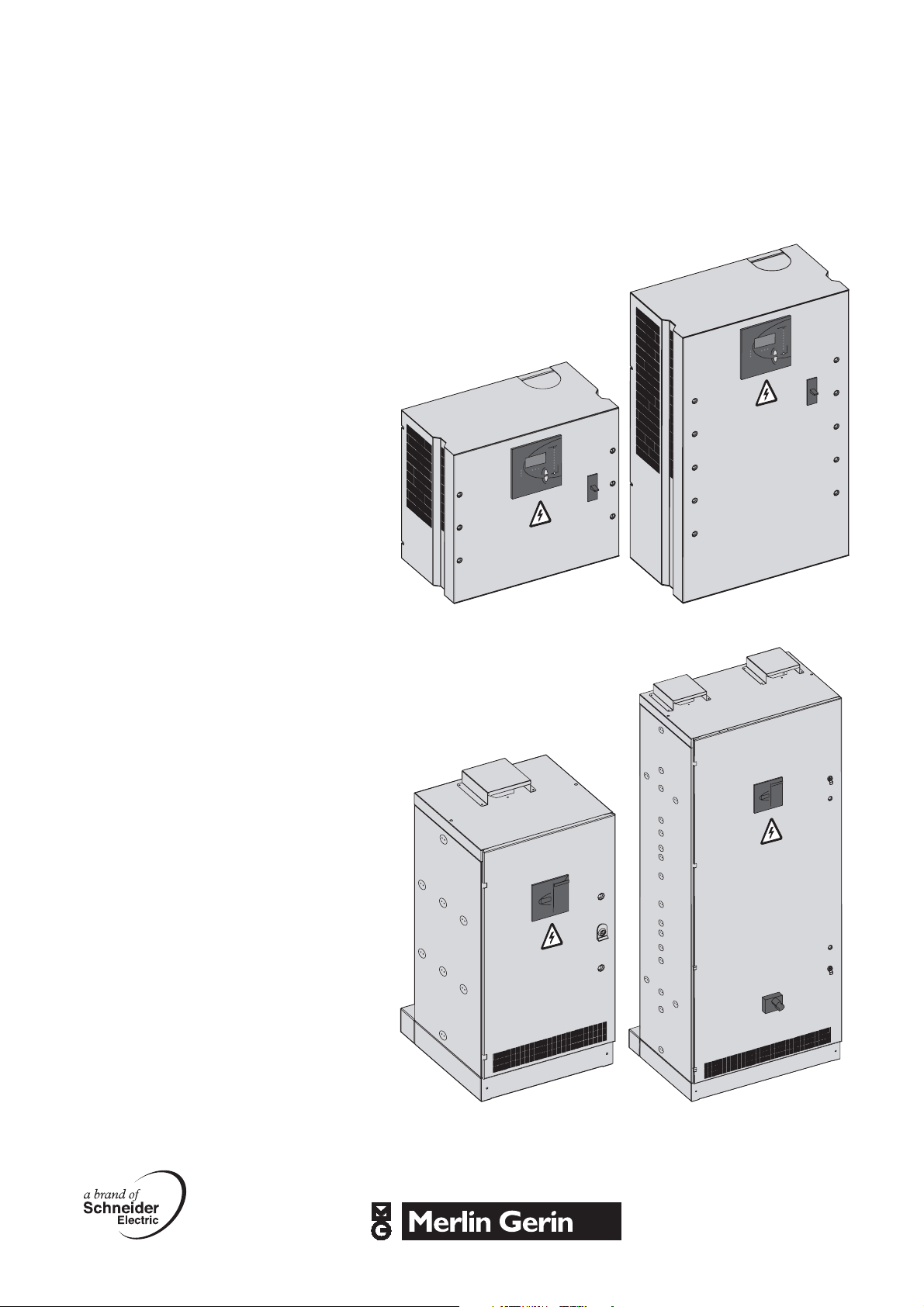
Varset
Automatic low voltage
capacitor banks
Panels and cubicles
C1 panel C2 panel
A1 cubicle A3 cubicle
Page 2

DB108739
For all panels and cubicles.
DB108740
Reception
Presentation
Varset is an automatic capacitor bank in the form of:
b panels
b cubicles.
The cubicles can be fitted with harmonic filter reactors.
Reception of equipment
b the addressee is always responsible for the risks and perils of
transporting our goods
b we decline all responsibility for missing items or damage attributable to
the carrier. If need be, send your complaints by registered mail to the carrier
b make sure there are no missing items and that the equipment has not
been subject to a shock likely to have affected its insulation or operation
b check the electrical characteristics indicated on the rating plate
correspond to those on the order form
b in the event of a non-conformity, indicate the shipping note reference
when submitting your complaint.
For A3 cubicles.
DB108741
For A3 bis, A4 and A4 bis cubicles.
Handling
b unpack the equipment at the place where it is to be installed
b it is preferable to use a forklift truck
b for the A3 cubicle, handle in the vertical position using
2 lifting rings
b to handle A3 bis, A4 and A4 bis cubicles in the vertical position, 4 lifting
rings must be used
b avoid shocks and deformation to the equipment.
Storage
b store the devices in a dry and well ventilated place that is sheltered from
rain, water projections, chemical agents and dust
b storage temperature: -20 °C to +45 °C.
Warranty
The equipment is factory cabled and inspected. Any modification to the
equipment jeopardizes its warranty.
2 AAV31918_00
Page 3

Technical characteristics
b voltage, frequency, power, as per rating plate
b rating tolerances: -5, +10 %
b allowable voltage overload
(8 h out of 24 h as defined in IEC 831-1/2): 10 %
b insulation voltage: 690 V
v 50 Hz, 1 min withstand: 2.5 kV
b ambient temperature in premises:
v maximum temperature: 40 °C
v average temperature over a 24 hour period:
35 °C
v average temperature over a 1 year period:
25 °C
v minimum temperature: -5 °C
b maximum dissipated power:
v 2.7 W/kVAr for Classic cubicles
v 3.1 W/kVAr for Comfort cubicles
v 8.7 W/kVAr for Harmony cubicles
b protection degree: IP31 (apart for the ventilator
outlet: IP21D)
b load shedding (normal-standby)
b colour:
v sheet steel: RAL 9001
v base: RAL 7021
b compliant with IEC 60439-1
and IEC 61921.
Description
DB110688
Fig. 1: electrical layout diagram, Classic and Comfort cubicles.
DB110689
Fig. 2: electrical layout diagram, Harmony cubicles.
3AAV31918_00
Page 4
Description (cont.)
DB110699
C1 panel
Fig. 3: C1 and C2 panels.
DB110700
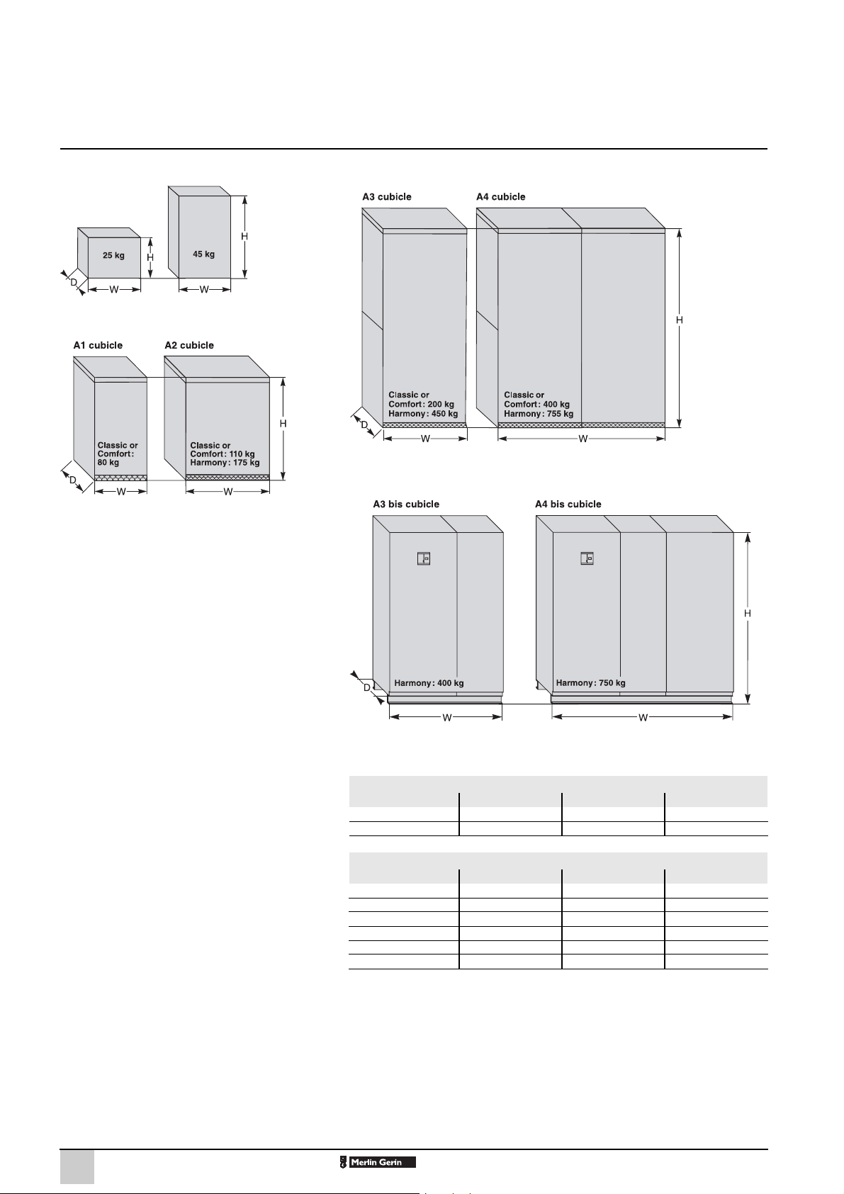
Fig. 4: A1 and A2 cubicles.
C2 panel
Sizes and weights (Figs. 3 to 7)
DB110701
Fig. 5: A3 and A4 cubicles.
DB110702
Fig. 6: A3 bis cubicle. Fig. 7: A4 bis cubicle.
Panel sizes (mm)
C1 panel 450 500 275
C2 panel 800 500 275
H W D
Cubicle sizes (mm)
A1 cubicle 1100 550 600
A2 cubicle 1100 800 600
A3 cubicle 2000 800 600
A3 bis cubicle 2000 1350 600
A4 cubicle 2000 1600 600
A4 bis cubicle 2000 2150 600
H W D
4 AAV31918_00
Page 5

DB110543
Fig. 8: C1 and C2 panels.
DB110498
Fig. 9: A1 cubicle.
Description (cont.)
Components
DB110497
DB110499
A : step switching control contactors
B : capacitors
C : current transformer connection terminal
D : control circuit protection fuses
E : power cable connection pads
F : ventilator depending on power rating
G : air vents
H : voltage transformer depending on range
I : harmonic filter reactors depending on range
J : main busbar
K : Varmetric controller
L : protective circuit-breaker depending on range
M : earthing.
DB110500
Fig. 10: Classic or Comfort A3 cubicle.
DB110577
DB110501
DB110578
Fig. 11: Harmony A3 cubicle.
5AAV31918_00
Page 6

Installation
Ambient air temperature
The ambient air temperature surrounding the electrical cubicle must be
within the following limits:
b maximum temperature: 40 °C
b average temperature over a 24 hour period: 35 °C
b average temperature over a 1 year period: 25 °C
b minimum temperature: -5 °C.
Ventilation rules
b place the equipment in well ventilated premises
b check maximum temperature limits are not exceeded when
the equipment is in operation (see the "ambient air temperature" paragraph
above)
b make sure the air vents are not covered
(minimum space 100 mm)
b ensure the equipment is sheltered from dust and humidity.
DB110694
Fig. 12: air flow.
6 AAV31918_00
Page 7

Electrical connections
The electrical connections are to be made as
shown in
the electrical diagrams, (page 3, Figs. 1 and 2)
Connection of the
current circuit
b current transformer / controller connection
cable cross-section: 2.5 mm2 minimum.
Installation of CT
(current transformer)
If there is an existing CT:
b ensure it is placed upstream of the installation,
capacitor bank included (Fig. 13)
b ensure it has a 5A secondary
b ensure it has a power rating greater than
5 VA
b connect the varmetric controller in series with
the existing circuit.
If a CT has to be fitted:
b the current transformer must be fitted to one
phase of the MLVS upstream of the capacitor
bank and the loads (motors, etc.) (Figs. 13, 14)
P1 to the transformer or source side
P2 to the load and capacitor bank side
b ensure it has a 5A secondary
b ensure it has a power rating greater than
5 VA.
Installation (cont.)
DB108778
Fig. 13: Installation electrical diagram.
DB108782
Fig. 14: 3-phase diagram of CT connection.
DB108755
.
CT connection
b identify the phase onto which the CT is placed
as phase L1 (Fig. 14)
b ensure that phase L1 of the capacitor bank is
connected to the busbar fitted with the CT (Fig.
14)
b connect the cables from the CT to the terminal
block, S1 to terminal K and S2 to terminal L (Fig.
15 and diagrams Figs. 1 and 2, page 3).
Earth connection
(Fig. 16)
The capacitor bank must be earthed using the
terminal intended for this purpose.
Load shedding
The terminals marked 1L3 and 2L3 are linked
using jumper A. To be able to shed load, replace
the jumper with one of the installation's normallyclosed contacts (Figs. 17, 18, 19).
Fig. 15: connection of CT to terminal block.
DB110511
Fig. 16: earth connection: horizontal
or vertical.
DB110509
Fig. 18: terminal block without load shedding. Fig. 19: terminal block with load shedding.
DB110695
Fig. 17: connection of load shedding contact.
DB110510
7AAV31918_00
Page 8

Installation (cont.)
Choice of cables
For an ambient temperature of 40 °C,
the temperature inside the cubicle can
reach 55°C.
Sizing current
The connection cables to the power factor
correction cubicle must be sized for the following
maximum continuous currents Imp:
Model Imp
Classic 1.36 In
Comfort 1.50 In
Harmony 135 Hz 1.10 In
Harmony 190 Hz 1.19 In
Harmony 215 Hz 1.31 In
Minimum sizing rules not taking into consideration any
correction factors: temperature, installation method.
Power factor correction cubicle nominal
current:
In =
Cross-section
It must be compatible with:
b the ambient temperature around the conductor
b the installation method (trunking, duct, etc.)
b the cable manufacturer's recommendations.
Q where U = mains supply voltage
U3
Q = reactive power
of the cubicle
Power circuit connection
DB110532
Fig. 20: power connection to circuit-breakers
(A3 bis, A4 bis, A2 Harmony).
DB110548
DB110531
Fig. 22: power connection to terminal blocks.
DB110597
Fig. 23: power connection to Polybloc.
DB108761
Connection methods
b to circuit-breakers (Fig. 20)
b to terminal blocks (Fig. 22)
b to connection pads (Figs. 21, 24)
b to Polybloc (Fig. 23).
Tightening torques
b cables connected to terminal blocks must be
tightened to 42 Nm max.
b cables connected to connection pads must be
tightened to 50 Nm max.
For cables connected to circuit-breakers,
refer to the user guide.
Fig. 21: power connection
to connection pads (A1 and A2 cubicles).
Fig. 24: power connection
to connection pads (A3 and A4 cubicles).
For A4 cubicles, the supply is spread over
two columns.
8 AAV31918_00
Page 9

DB108763
Controller front face.
Commissioning
Configuring the Varlogic controller
NR6/NR12
Setting the controller
The varmetric controller has been configured in accordance with the
capacitor bank's characteristics.
The only operations that have to be carried out during commissioning are:
Φ
b target cos
b current transformer ratio configuration.
Important:
b if supplied by a summing CT (installation with several incoming
transformers), it is the sum of the ratios of the different measurement CTs
that must be taken into consideration
b for an installation equipped with a generator set (load shedding),
the capacitor bank must be taken out of circuit, by breaking the supply to
the controller, before switching to the generator set.
See page 7, "connection of current circuit".
setting if necessary
Commissioning the capacitor bank
When first energised, the controller will immediately ask you to enter the
user language.
Choose the desired language using the keys and then validate by
pressing Enter.
The parameters needed for correct capacitor bank operation
are factory set.
Some parameters depend on the installation's characteristics
and must be modified on-site during commissioning
b target cos
b current transformer ratio in order to display the measured values correctly
b response current (C/K): this value is automatically searched for during the
checking phase.
The other parameters must not be changed.
In particular, the time delay must never be less than 50 s, otherwise
there is a risk the capacitor bank will incur serious damage and will no
longer be covered by the warranty.
b the "MIS.SERV" menu must be used to launch the commissioning
sequence. The sequence includes the configuration of cos
transformation ratio, as well as an automatic check that the parameters
entered are compatible with the installation's actual parameters.
Note : if an alarm appears during commissioning or when first used, refer to the
“faults and solutions” paragraph to determine its origin.
Φ
(default value = 1)
+
-
Φ
and the
Checking correct operation
b check that cos Φ corresponds to the required value
b if operating on full load, check the switched stepping functions correctly
b after several hours' operation, check the temperature in the premises.
For a better understanding of the parameters to be defined, refer to the
Glossary (Chapter 7) in the controller manual.
9AAV31918_00
Page 10

Commissioning (cont.)
DB108779
Commissioning a pre-configured capacitor bank.
What to do in the event of an error?
"Error codes" allow a diagnosis to be made and a solution to be found.
Refer to chapter 5.4 of the controller manual.
After checking the installation, re-launch the "MIS.SERV" sequence or the
commissioning with automatic configuration "REG.AUTO" sequence.
If the controller is not solicited for a long period when a menu is run, it may
display the message "I FAIBLE"
To return to the commissioning ("MIS.SERV") menu, or any other menu,
press and then scroll through the menus to obtain the one required.
esc
10 AAV31918_00
Page 11

Commissioning (cont.)
Configuring the Varlogic controller RT6
PB100045-55
Setting the controller
The varmetric controller has been configured in accordance with the
capacitor bank's characteristics.
The only operations that have to be carried out during commissioning are:
b target cos
b current transformer ratio configuration.
Important:
b if supplied by a summing CT (installation with several incoming
transformers), it is the sum of the ratios of the different measurement CTs
that must be taken into consideration
b for an installation equipped with a generator set (load shedding),
the capacitor bank must be taken out of circuit, by breaking the supply
to the controller, before switching to the generator set.
See page 7, "connection of current circuit".
Φ
setting if necessary
Commissioning the capacitor bank
The parameters needed for correct capacitor bank operation
are factory set.
Some parameters depend on the installation's characteristics
and must be modified on-site during commissioning
b target cos
b current transformer ratio in order to display the measured values correctly
b response current (C/k): this value is automatically searched for during the
C/k automatic setting sequence.
The other parameters must not be changed.
In particular, the time delay must never be less than 50 s, otherwise
there is a risk the capacitor bank will incur serious damage and will no
longer be covered by the warranty.
Φ
(default value = 1)
Checking correct operation
b check that cos Φ corresponds to the required value
b if operating on full load, check the switched stepping functions correctly
b after several hours' operation, check the temperature
in the premises.
For a better understanding of the parameters to be defined,
refer to the Varlogic RT6 manual.
11AAV31918_00
Page 12

Commissioning (cont.)
Automatic setting
of the C/k value
DB108812
DB110549
To start the C/k setting process,
simultaneously press
the UP and DOWN keys
.
Setting cos Φ
Start the SET menu by pressing the
SET key for 3 seconds.
AUtO
Display
Use the UP and DOWN keys to
select the cos
Φ LED.
The cos symbol is displayed.
Select the cos
Φ setting
by pressing the SET key.
The previously configured value is
displayed.
Choose a value between 0.85 and
1.00 using the UP-DOWN keys.
When the target value is displayed,
save it by pressing the SET key.
The RT6 then goes back to its
normal operating mode.
Selecting the transformer primary
current
DB108814
DB110550
Start the SET menu by pressing the
SET key for 3 seconds.
AUtO
Display
Select the CT LED using the
UP-DOWN keys. The CT symbol
is
displayed.
Select the transformer primary
current value by pressing the SET
key. The previously configured CT
value is displayed.
Choose a value between 5 and
10,000 using the UP-DOWN keys.
When the target value is displayed,
save it by pressing the SET key.
The RT6 then goes back to its
normal operating mode.
12 AAV31918_00
Page 13

Commissioning (cont.)
Varlogic NR6/NR12 faults and solutions
An operating problem, when commissioning
a capacitor bank, can generally be diagnosed from
the information supplied by the controller.
Controller display Possible causes Solutions
No display b no supply to controller v check for voltage at the controller's
b overvoltage v the controller has been damaged by a supply
Low (i.e. low current)
A3 or A5 alarm
(abnormal cos
(capacitive cos Φ) b incorrect voltage configuration v check the controller's voltage configuration (LL
Alarm A1 (lack of kVAr)
(1) The CT must be fitted on phase L1, upstream of the installation to be corrected. It must be checked that phase L1 at the point the CT is connected corresponds
to phase L1 inside the capacitor bank (e.g. by checking that the voltage between these two points = 0).
Φ
)
b non-compliant wiring v check the position of the CT in the (low current)
b CT oversized or too lower load v check the CT has been correctly chosen
b faulty CT v replace the CT
b bad connection v check the position of the CT
b presence of fixed capacitor bank(s) with low load
levels
b bad connection v check the position of the CT in the installation
b no auxiliary voltage v check the protection status of the auxiliary circuit
b incorrect C/K configuration v carry out the C/K automatic configuration again or
b target cos Φ occasionally not reached v deactivate alarm A1
b target cos Φ too high v readjust the target cos
b lack of reative power
(undersized capacitor bank)
terminals
v if there is no voltage reading, check circuit continuity
from the source: wiring, fuses, etc.
overvoltage.
Replace the controller
installation
v check the short-circuit jumper is present between
terminals K-L
in the installation
display)
v deactivate alarm A5
manually configure the calculated value
(1)
(1)
(1)
Φ
v add more capacitors
13AAV31918_00
Page 14

Commissioning (cont.)
Faults and solutions for Varlogic RT6
Errors and alarms
The alarm relay is activated if the following "errors" occur.
Overvoltage
If the voltage between phases equals or exceeds the pre-defined value
(programmable between 185...265 V for 240-275 V and between
320...460 V for 410-480 V), the RT6 waits for 1 minute. If the overvoltage is
still present at the end of this 1 minute period, the "OVER VOLTAGE" LED
lights-up. Depending on the programmed overvoltage protection
configuration, the RT6 switches all the capacitor steps or continues
to achieve power factor correction (refer to chapter 5.9 of the Varlogic RT6
manual).
Low power factor
When the power factor does not reach the target value, despite having
switched-in all the capacitor steps, the low power factor LED lights-up and
the alarm relay is activated after 1 minute.
Overcorrection
If the system is still capacitive despite having switched-out all the capacitor
steps, the "OVER COMPENSATION" LED lights-up and the alarm relay is
activated after 1 minute.
14 AAV31918_00
Page 15

DB110696
Fig. 25: on-line break.
DB110697
Maintenance
Personnel protection
Each capacitor is fitted with discharge resistors which reduce terminal
voltages to 50 V one minute after de-energising.
Before carrying out work on the equipment:
b remove its power supply
b wait until the compulsory discharge time has elapsed
b ensure each capacitor has been fully discharged by short-circuiting and
earthing the contactor terminals.
Discharging the capacitors
Warning:
refer to the capacitor bank's electrical diagram to identify the coupling mode
between the contactor and the capacitor.
b on-line break (Fig. 25).
To ensure capacitor discharge, successively short-circuit terminals: AB, AC
and BC
b break the triangle links (Fig. 26).
To ensure capacitor discharge, successively short-circuit terminals: AE, BF
and CD.
Fig. 26: break the triangle links.
Checks
One month after energising, check:
b contactor terminal tightening torques.
Each year check:
b general cleanliness of the equipment
b filters and ventilation system
b terminal tightening torques.
b proper working order of switching and protective devices
b temperature in the premises: -5 °C to +40 °C max
b capacitor capacitance, consult us if the capacitance value has
changed by more than 10 %.
Safety
All the operations described in this guide must be carried out whilst
respecting current safety standards, and under the responsibility
of a competent authority.
15AAV31918_00
Page 16

Maintenance (cont.)
Working on the current circuit
Before starting work
DB109732
Initial state.
A : separator
B : jumper
K : S1 terminal on CT
L : S2 terminal on CT
Fig. 27.
DB109735
DB109733
Remove the separator from
the circuit A.
After finishing work
DB109736
DB109734
Use the jumper B to link
DB109735
Final state.
terminals K and L
of the terminal block
(terminals S1
and S2 of the CT).
Warning
Risk of destroying the current transformer
if the secondary is open-circuit.
DB109737
DB109738
Initial state. Disconnect the jumper B
by lifting it up.
Fig. 28.
Schneider Electric Industries SAS
Rectiphase
399 rue de la Gare
74370 Pringy
France
Tel.: 33 (0)4 50 66 95 00
Fax: 33 (0)4 50 27 24 19
http://www.schneider-electric.com
http://www.merlin-gerin.com
No.AAV31918_00
As standards, specifications and designs change from time to time, please ask for confirmation
of the information given in the publication.
Creation: Schneider Electric, Ameg and Hardis Conseil
Publication: Schneider Electric
Printing: Coquand Imprimeur - made in France
Refit the separator A. Final state.
This document has been printed on ecological paper
© 2006 - Schneider Electric – All rights reserved
10-2006
 Loading...