

Varlogic NR6, NR12
Power factor controller
User manual

Table of Contents
1. General...................................................................................................3
1.1 Safety...............................................................................................3
1.2 Description.......................................................................................3
2. Installation ..............................................................................................5
3. Display....................................................................................................6
4. Start-up Procedure.................................................................................6
5. Menu Operations....................................................................................7
5.1 General.............................................................................................7
5.2 Main Menu .......................................................................................9
5.3 Bank Pre-Configuration .................................................................11
5.4 Commissioning ..............................................................................13
5.5 Auto Setup of Parameters .............................................................14
5.6 Manual Setup of Parameters .........................................................15
5.7 Measurement Menu.......................................................................17
5.8 Parameter Update..........................................................................18
5.9 Alarms Menu..................................................................................19
5.10 Maintenance Menu ......................................................................20
6. Miscellaneous.......................................................................................23
6.1 Stepping Programs........................................................................23
6.2 Manual calculation of response value............................................26
6.3 High Voltage use of NR6/NR12......................................................27
7. Glossary ...............................................................................................29
8. Technical specifications .......................................................................31
2
USER´S MANUAL
Power Factor Controller NR6 / NR12
USER’S MANUAL
3
USER´S MANUAL
1. General
1.1 Safety
The following precautions must be taken into account when installing and operating the controller
• The installation of the controller must be performed by a qualified electrician
• Do not touch the connectors when the controller is energized, make sure that
the operating voltage is disconnected before touching any parts located on the
rear side of the controller
• Do not open a live current circuit, this may cause dangerous overvoltages. Always
short circuit the current transformer (CT) before replacing or removing the controller
installed in a bank.
• Do not open the controller casing, there are no user serviceable parts inside
For better understanding of the terminology used, please refer to the Glossary
(chapter 7) at the end of this manual.
1.2 Description
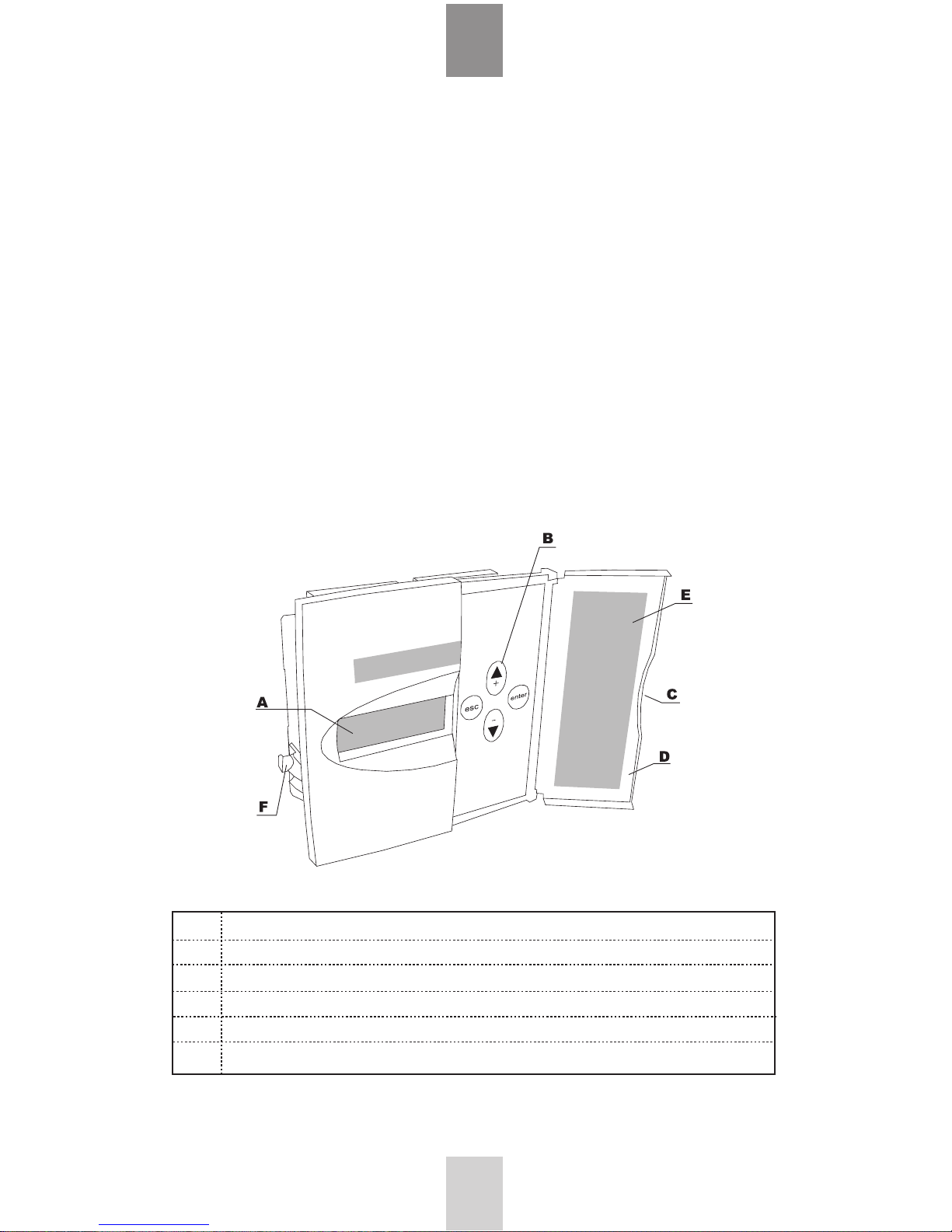
Front view:
Legend
A Display
B Keys
C Opening of door
D Door
E Alarm information
F Mounting bracket for panel mounting installation
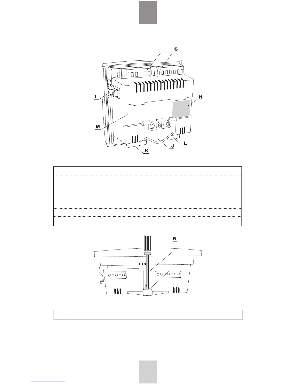
Rear view:
Legend
Side view:
Legend
See Chapter 8 for technical specifications.
4
USER´S MANUAL
G Step output connectors
H Specification label
I Mounting bracket for panel mounting installation
J Fixing spring for DIN-rail mounting
K Current/voltage connection inputs
L Fan and alarm outputs
M DIN-rail mounting installation area
N Screwdriver guide
5
USER´S MANUAL
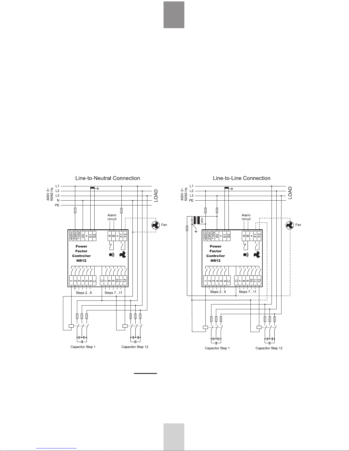
2. Installation
The controller is designed for either panel (cut-out 138 x 138 mm) or DIN-rail installation. It is
locked to the rail by a screwdriver-operated fixing spring and to a panel by a side fitting spring.
There are two ways of connecting the controller to the network.
Voltage LN (Line – Neutral) (CT on the same line phase)
Voltage LL (Line – Line) (CT on the third phase)
Incorrect connections can be automatically corrected by the controller when Auto Setup is
selected from the main menu.
Caution: For use in HV network, look first at chapter 6.3
Figure 1: Controller connections

6
USER´S MANUAL
3. Display
The controller is equipped with a backlighted LCD-display.
Figure 2 : Display layout and symbols
4. Start-up Procedure
Before connecting power, check the wiring of all controller terminals. Check carefully for correct
operating voltage. Selection of wrong voltage input can permanently damage the controller.
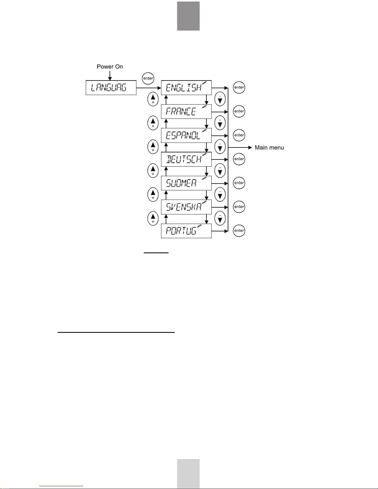
After the first power switch-on, the controller will automatically ask for the language setting of
the menu.
7
USER´S MANUAL
Figure 3: Language setting dialog
5. Menu Operations
5.1 General
Navigation between different menu levels
As a precaution against accidental use, the access of certain menus has been protected by a
keylock, which is a special sequence of keystrokes enabling the use the particular menu item.
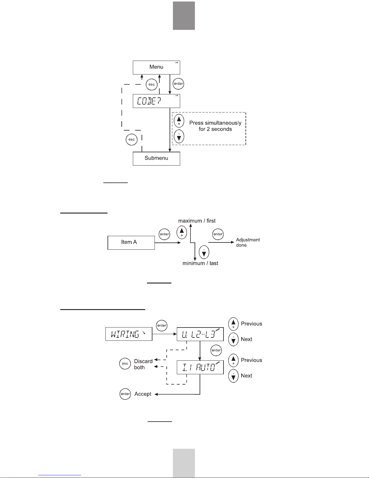
Figure 4: General way of entering the menu with a keylock
Adjusting a value
Figure 5: Adjusting a value
Special case: The wiring editor
Figure 6: The wiring editor
8
USER´S MANUAL
5.2 Main Menu
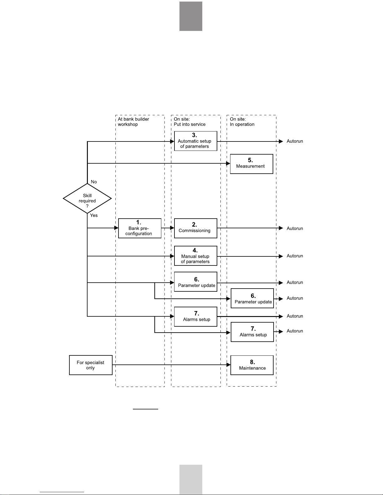
The main menu contains all basic submenus required to set up and operate the controller.
Which menu to choose?
Figure 7: Required skills and menu selection
If bank preconfiguration is properly done, commissioning does not require any special skill.
9
USER´S MANUAL

10
USER´S MANUAL
Figure 8: Main menu
(1) Bank pre-configuration
When factory settings have not been changed, this
menu provides the bank builder the means of preconfiguring the bank at the workshop. After preconfiguration, this menu topic is replaced by
(2) Commissioning, by which the controller is taken
into service.
(3) Automatic setup of parameters
In the event that the controller has not been preconfigured, an inexperienced user can automatically
set up all the characteristics of the bank and bring it
into service.
(4) Manual setup of parameters
In the event that the controller has not been preconfigured, an experienced user can manually set up
all the characteristics of the bank and bring it into
service.
(5) Measurement
The measurement menu contains the most common
measurements taken from the network and provides
some information about the bank. This is a read-only
menu.
(7) Alarm settings
To adjust status and parameters of alarms.
(8) Maintenance
The maintenance menu provides some useful
information about the usage of the bank, capacitors
and contactors. Some auxiliary settings and action
have also been provided. This menu is basically
intended for use by the manufacturer’s maintenance
team.
(6) Parameter update
At any time, an experienced user can access the most
common operating parameters from this menu. Unlike
the configuration and setup sequences, this is a menu
allowing a free and unrestricted entry into all its items
and should be used when an occasional parameter
access is needed.
 Loading...